CRUISE CONTROL
Cruise Control Wiring Diagram for Lincoln Navigator 1998
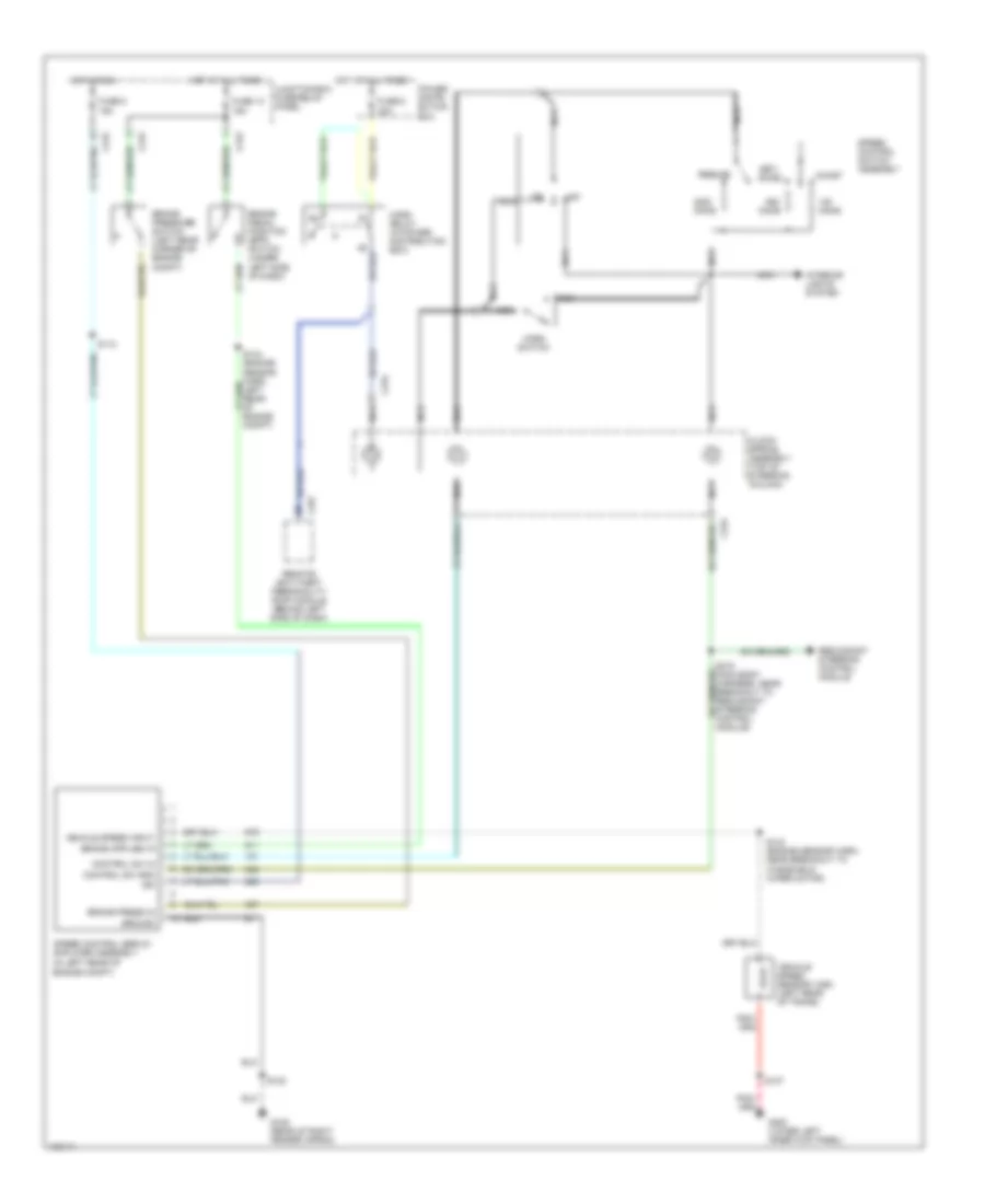
List of elements for Cruise Control Wiring Diagram for Lincoln Navigator 1998:
- 15a
- 20a
- Accel
- Brake pedal position (bpp) switch (under left side of dash)
- Brake press in
- Brake pressure switch (left rear corner of engine compt)
- C234
- C242
- C257
- Clock- spring assembly (top of steering column)
- Coast
- Control sw gnd
- Control sw in
- Fuse 13
- Fuse 5
- G105 (rear of right fender apron)
- G200 (lower left inner kick panel)
- Ground
- Horn relay (in power distribution box)
- Horn switch
- Hot at all times
- Hot in run
- Ign
- Interior lights system
- Junction box fuse/relay panel
- Nca
- Off
- Ohms
- Power distri- bution box
- Redundant steering control module
- Remote anti-theft personality (rap) module (behind left side of dash)
- Resume
- S102
- S107
- S112
- S143 (engine sensor harn, near breakout to windshield wiper motor)
- S144 (engine sensor harn, left rear of engine compt)
- S218 (main body harness, near breakout to redundant steering control module)
- Set/
- Speed control servo/ amplifier assembly (in left rear of engine compt)
- Speed control switch assembly
- Vehicle speed input
- Vehicle speed sensor (vss) (left rear of trans)
 Čeština
 Dansk
Dansk Deutsch
 Ελληνικά
 English
 English
 Español
 Suomi
Suomi Français
 Français
 עברית
עברית Hrvatski
 Magyar
 Italiano
 日本語
日本語 한국어
한국어 Polski
 Português
 Português
 Română
 Русский
 Slovenčina
 Slovenščina
 Svenska
 Türkçe
 中文 (中国)
 Nederlands