ANTI-LOCK BRAKES
Anti-lock Brake Wiring Diagrams for Ford Ranger 2002
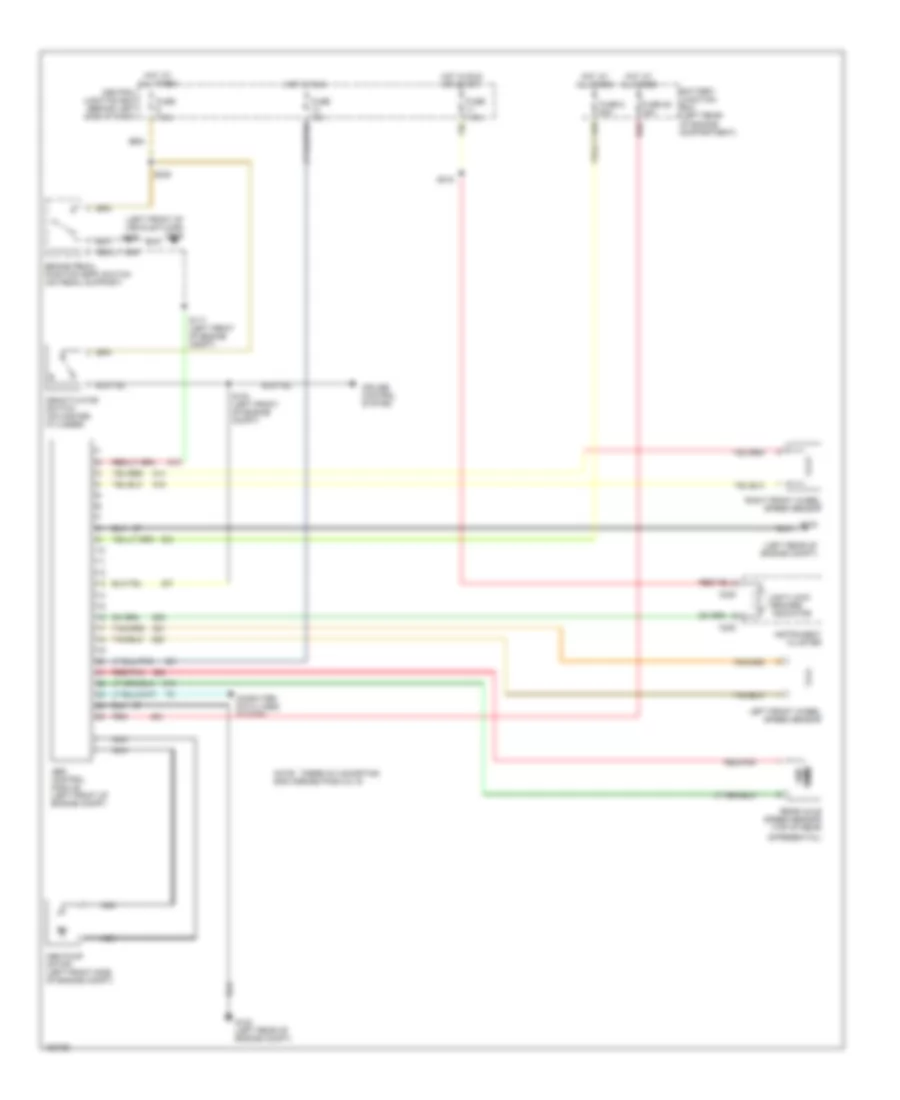
List of elements for Anti-lock Brake Wiring Diagrams for Ford Ranger 2002:
- (left front of vehicle floor) g205
- (left rear of engine compt)
- Abs control module (left front of engine compt)
- Abs pump motor (left front side of engine compt)
- Anti-lock brakes indicator
- Battery junction box (left rear of engine compartment)
- Brake pedal position (bpp) switch (on pedal support)
- C220
- Central junction box (behind left side of dash)
- Computer data lines system
- Cruise control system
- Deactivator switch (on master cylinder)
- Differential)
- Fuse 10a
- Fuse 28 30a
- Fuse 6 50a
- Fuse 7.5a
- G102
- G102 (left rear of engine compt)
- Hot at all times
- Hot in run
- Hot in run or start
- Instrument cluster
- Left front wheel speed sensor
- Nca
- Note: there is a shorting bar across pins 8 & 16
- Ohms
- Rear axle speed sensor (top of rear
- Red
- Red/pnk
- Right front wheel speed sensor
- S103 (left front of engine compt)
- S117 (left front of engine compt)
- S218
- S238
 Čeština
 Dansk
Dansk Deutsch
 Ελληνικά
 English
 English
 Español
 Suomi
Suomi Français
 Français
 עברית
עברית Hrvatski
 Magyar
 Italiano
 日本語
日本語 한국어
한국어 Polski
 Português
 Português
 Română
 Русский
 Slovenčina
 Slovenščina
 Svenska
 Türkçe
 中文 (中国)
 Nederlands