ANTI-LOCK BRAKES
Anti-lock Brakes Wiring Diagram, Early Production for BMW 535i GT 2013
 https://portal-diagnostov.com/license.html
Automotive Electricians Portal FZCO
Automotive Electricians Portal FZCO
https://portal-diagnostov.com/license.html
https://portal-diagnostov.com/license.html
Automotive Electricians Portal FZCO
Automotive Electricians Portal FZCO
List of elements for Anti-lock Brakes Wiring Diagram, Early Production for BMW 535i GT 2013:
- (center rear of luggage compt) parking brake control unit
- (left end of dash) central gateway module
- (left front of luggage compt) (w/o navigation) telematic control unit
- (left rear engine compt) brake fluid level switch
- (top of brake pedal assembly) (hybrid) brake pedal travel sensor
- 13b
- Brake light switch (left side of dash)
- Brk light
- Bus sig
- Car access system (lower left center of dash)
- Computer data lines system
- Dynamic stability control (dsc) (under right front of vehicle)
- Except gt
- Exterior lights system
- Fun ind
- Fuse 30a
- Fuse 50a
- Fuse 5a
- Gnd brk pdl sens
- Ground
- Hot at all times
- Hot w/ bistable relay energized
- Junction box (right side of dash)
- Left front brake pad wear sensor (behind left front wheel)
- Left front wheel speed sensor (front of left front wheel)
- Left rear wheel speed sensor (front of left rear wheel)
- Lf brk pad
- Lf whl spd
- Lr whl spd
- Nca
- Parking brake button
- Pnk
- Power distribution system
- Red
- Rf whl spd
- Right front wheel speed sensor (behind right front wheel)
- Right rear brake pad wear sensor (behind right front wheel)
- Right rear wheel speed sensor (front of right rear wheel)
- Rr brk pad
- Rr whl spd
- Sens gnd
- Steering column switch cluster
- Sw sig
- Switch sig
- Term 30
- Travel sens
- Wake up
- Whl spd sig
- X188 1b
- Z10 4b (left kick panel)
- Z10 9b (left kick panel)
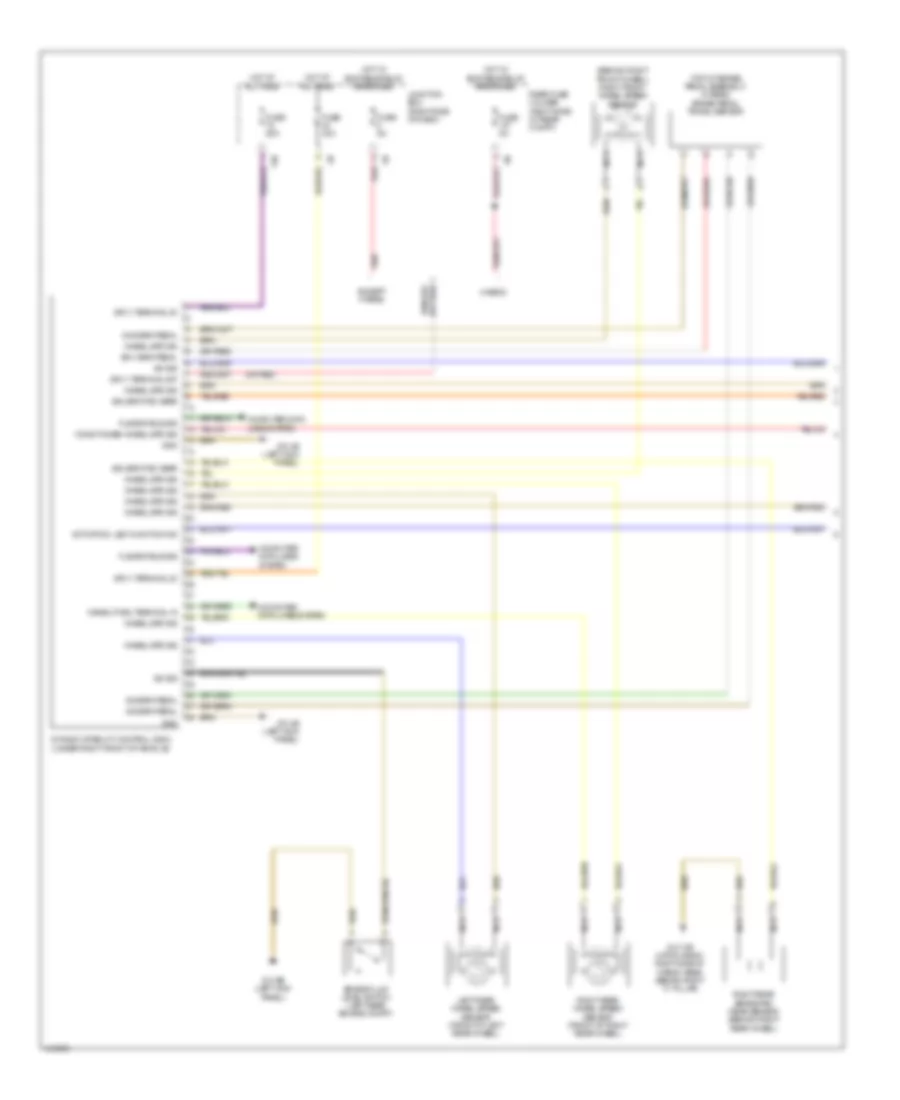
Anti-lock Brakes Wiring Diagram, Late Production (1 of 2) for BMW 535i GT 2013
List of elements for Anti-lock Brakes Wiring Diagram, Late Production (1 of 2) for BMW 535i GT 2013:
- (behind right front wheel) right front wheel speed sensor
- (or red)
- (top of brake pedal assembly) (hybrid) brake pedal travel sensor
- 13b
- Activation, led function ind
- Brake fluid level switch (left rear engine compt)
- Computer data lines system
- Conditioned wheel spd sig
- Dynamic stability control (dsc) (under right front of vehicle)
- Except hybrid
- Flexray bus sig
- Fuse 30a
- Fuse 50a
- Fuse 5a
- Gnd
- Gnd brk pedal
- Hot at all times
- Hot w/ bi-stable relay energized
- Hybrid
- Junction box (right side of dash)
- Left rear wheel speed sensor (front of left rear wheel)
- Nca
- Rear fuse holder (right side of rear compt)
- Red
- Right rear brake pad wear sensor (behind right rear wheel)
- Right rear wheel speed sensor (front of right rear wheel)
- Sig brk pedal
- Sig, brk pad wear
- Sply brk pedal
- Sply, terminal 30
- Sply, terminal 30f
- Sw sig
- Wake-up sig, terminal 15
- Wheel spd sig
- Z10 13b (hatch back: right side of cargo area) (sedan: right "c" pillar)
- Z10 4b (left kick panel)
- Z10 9b (left kick panel)
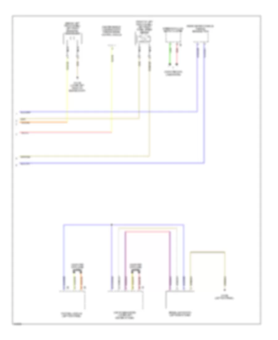
Anti-lock Brakes Wiring Diagram, Late Production (2 of 2) for BMW 535i GT 2013
List of elements for Anti-lock Brakes Wiring Diagram, Late Production (2 of 2) for BMW 535i GT 2013:
- (behind left front wheel) left front brake pad wear sensor
- (center rear of luggage compt) parking brake control module
- (front of left front wheel) left front wheel speed sensor
- (rear center console) parking brake button
- Brake light switch (left side of dash)
- Car access system (lower left center of dash)
- Computer data lines system
- Footwell module (left kick panel)
- Nca
- Red
- Steering column switch cluster
- Z10 2b (lower left front of engine compt)
- Z10 9b (left kick panel)

 Čeština
 Dansk
Dansk Deutsch
 Ελληνικά
 English
 English
 Español
 Suomi
Suomi Français
 Français
 עברית
עברית Hrvatski
 Magyar
 Italiano
 日本語
日本語 한국어
한국어 Polski
 Português
 Português
 Română
 Русский
 Slovenčina
 Slovenščina
 Svenska
 Türkçe
 中文 (中国)