
 Čeština
 Dansk
Dansk Deutsch
 Ελληνικά
 English
 English
 Español
 Suomi
Suomi Français
 Français
 עברית
עברית Hrvatski
 Magyar
 Italiano
 日本語
日本語 한국어
한국어 Polski
 Português
 Português
 Română
 Русский
 Slovenčina
 Slovenščina
 Svenska
 Türkçe
 中文 (中国)

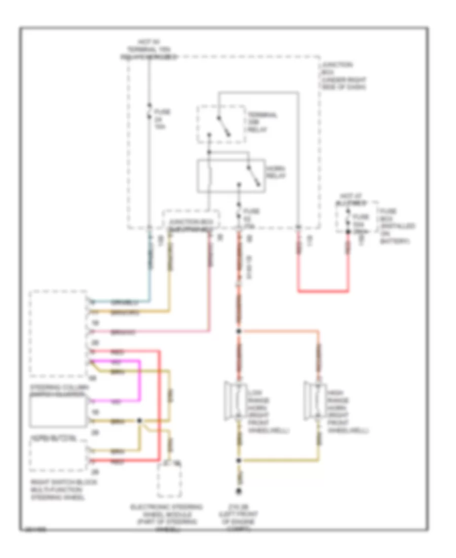
HORN
Horn Wiring Diagram for BMW 650xi 2012
List of elements for Horn Wiring Diagram for BMW 650xi 2012:

AIR CONDITIONINGANTI-LOCK BRAKESANTI-THEFTBODY CONTROL MODULESCOMPUTER DATA LINESCOOLING FANCRUISE CONTROLDEFOGGERSELECTRONIC POWER STEERINGEXTERIOR LIGHTSELECTRONIC SUSPENSIONENGINE PERFORMANCEGROUND DISTRIBUTIONHEADLIGHTSINTERIOR LIGHTSINSTRUMENT CLUSTERHORNMEMORY SYSTEMSNAVIGATIONPOWER SEATSPOWER DISTRIBUTIONPOWER MIRRORSRADIOPOWER DOOR LOCKSPOWER TOP/SUNROOFPOWER WINDOWSSTARTING/CHARGINGSUPPLEMENTAL RESTRAINTSSHIFT INTERLOCKTRANSMISSIONWARNING SYSTEMSTRUNK, TAILGATE, FUEL DOORWIPER/WASHER