WARNING SYSTEMS
Chime Wiring Diagram for BMW 540i 1998
 https://portal-diagnostov.com/license.html
Automotive Electricians Portal FZCO
Automotive Electricians Portal FZCO
https://portal-diagnostov.com/license.html
https://portal-diagnostov.com/license.html
Automotive Electricians Portal FZCO
Automotive Electricians Portal FZCO
List of elements for Chime Wiring Diagram for BMW 540i 1998:
- Chime module (above driver footwell)
- Driver's door jamb switch
- Fuse f24 5a
- Fuse panel 1
- General module
- Hot at all times
- Instrument cluster
- Interior lights system
- X10113
- X1108 (driver footwell)
- X11176
- X173 (driver door sill)
- X253
- X254
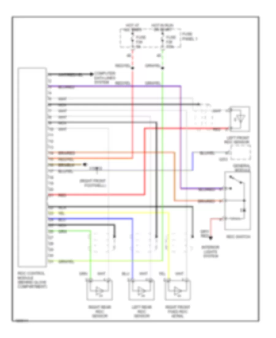
Tire Pressure Monitoring Wiring Diagram for BMW 540i 1998
List of elements for Tire Pressure Monitoring Wiring Diagram for BMW 540i 1998:
- (right front footwell)
- Computer data lines system
- Fuse f20 7.5a
- Fuse f24 5a
- Fuse panel 1
- General module
- Hot at all times
- Hot in run or start
- Interior lights system
- Left front rdc sensor
- Left rear rdc sensor
- Nca
- Rdc control module (behind glove compartment)
- Rdc switch
- Red
- Right front fixed rdc aerial
- Right rear rdc sensor
- X10012
- X253

 Čeština
 Dansk
Dansk Deutsch
 Ελληνικά
 English
 English
 Español
 Suomi
Suomi Français
 Français
 עברית
עברית Hrvatski
 Magyar
 Italiano
 日本語
日本語 한국어
한국어 Polski
 Português
 Português
 Română
 Русский
 Slovenčina
 Slovenščina
 Svenska
 Türkçe
 中文 (中国)