AIR CONDITIONING
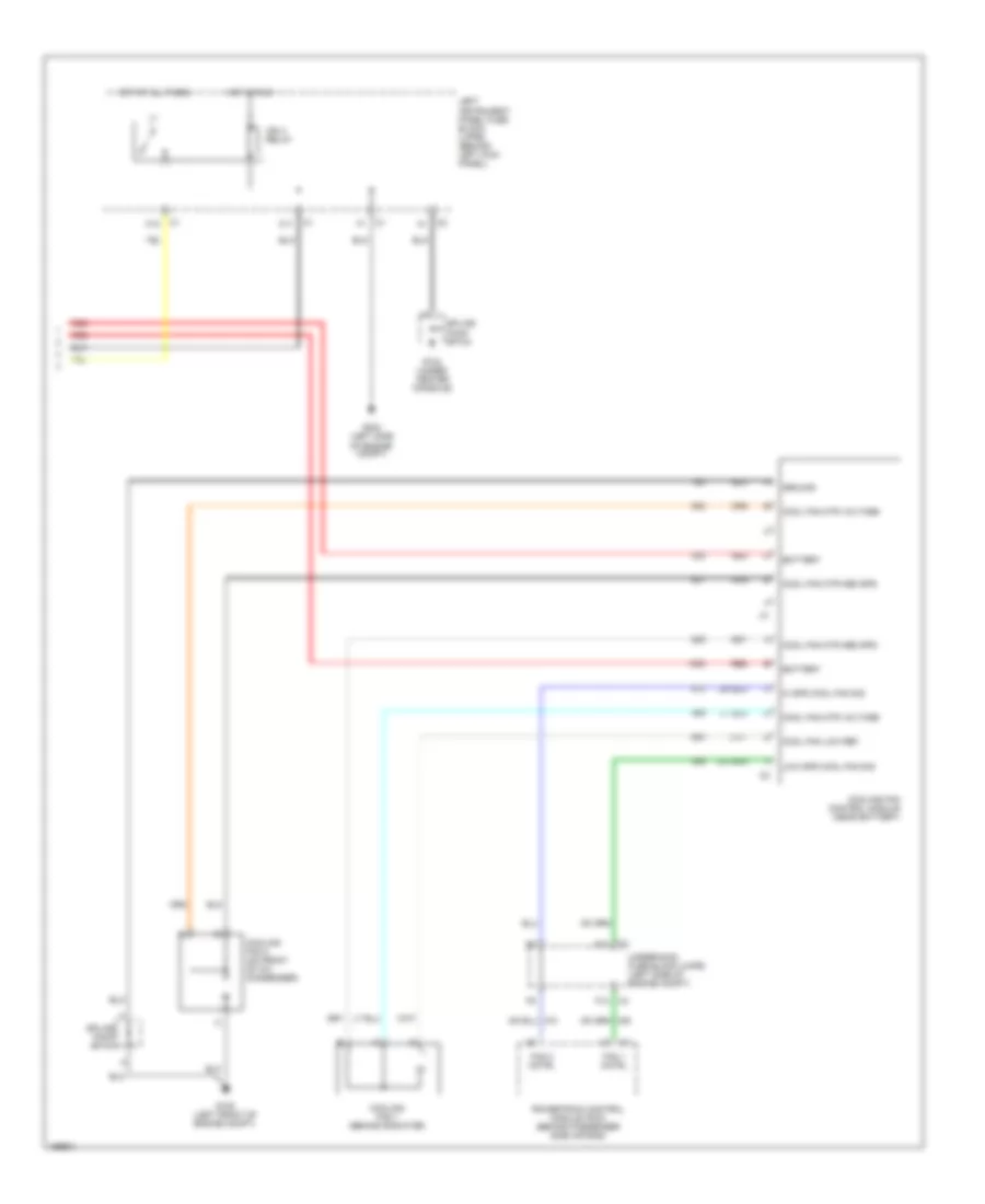
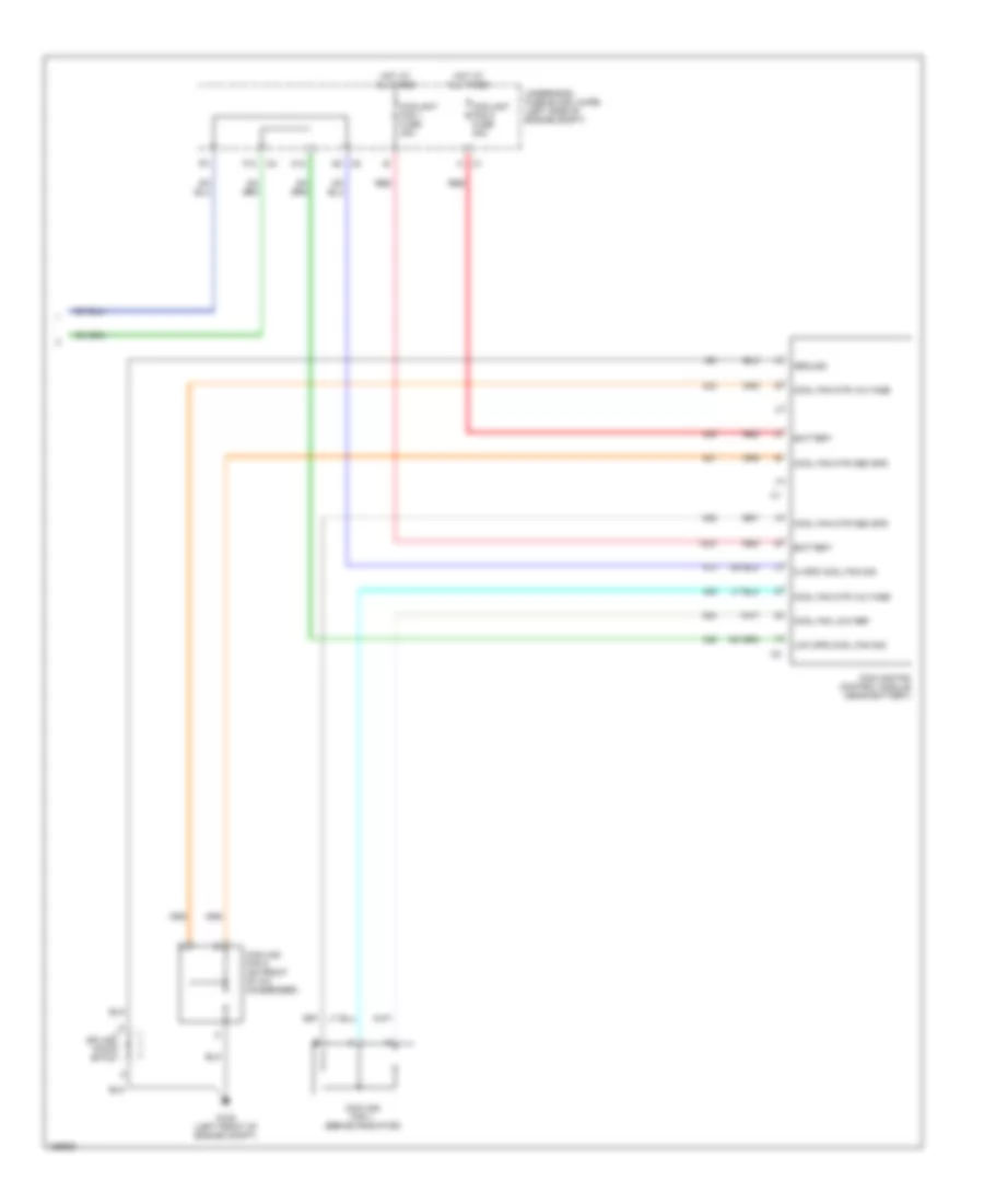
Automatic A/C Wiring Diagram (1 of 2) for Saturn L200 2003
 https://portal-diagnostov.com/license.html
Automotive Electricians Portal FZCO
Automotive Electricians Portal FZCO
https://portal-diagnostov.com/license.html
https://portal-diagnostov.com/license.html
Automotive Electricians Portal FZCO
Automotive Electricians Portal FZCO
List of elements for Automatic A/C Wiring Diagram (1 of 2) for Saturn L200 2003:
- (in hvac harn) s205
- +5v
- 5v ref
- A/c
- A/c diode
- A/c fuse 10a
- A/c press
- A/c pressure sensor (in a/c high side pressure line)
- A/c relay
- A10
- Air tmp cntrl
- Amb air temp
- Amb temp dr
- Ambient air temperature sensor (left front of engine compt)
- Ambient light sensor (near base of wind- shield)
- B10
- Battery
- Bcm fuse 10a
- Blower motor (on hvac assembly)
- Blower motor speed control module (on front of hvac assembly)
- Blw mtr spd
- Blwr mtr spd
- Body control module (bcm) (mounted to top of glove box)
- Compressor clutch
- Computer data lines system
- Coolant fan 1 fuse 30a
- Coolant fan 2 fuse 30a
- G118 (on front of engine block, above starter)
- G305 (under center console)
- Gnd
- Hot at all times
- Hot in run
- Hvac control module (center of instrument panel, under radio)
- Ign 3 fuse 10a
- Ign 3 volt
- Left instrument panel fuse block (lipfb) (behind left kick panel)
- Low ref
- Mode actuator (on hvac assembly)
- Mode dr mtr
- Mode dr pos
- Powertrain control module (pcm) (behind passenger sie air bag)
- Rec dr cntrl
- Recirculation door actuator (on hvac assembly)
- Red
- Return
- Serial data
- Spd req sig
- Sunld sen sig
- Temperature actuator (on right end of hvac assembly)
- Underhood fuse block (uhfb) (left side of engine compt)
Automatic A/C Wiring Diagram (2 of 2) for Saturn L200 2003
List of elements for Automatic A/C Wiring Diagram (2 of 2) for Saturn L200 2003:
- A12
- Battery
- C11
- C12
- Cool fan low ref
- Cool fan mtr med spd
- Cool fan mtr voltage
- Cooling fan 1 (behind radiator)
- Cooling fan 2 (on front of a/c condenser)
- Cooling fan control module (near battery)
- F12
- Fan 1 cntrl
- Fan 2 cntrl
- G104 (under center console)
- G105 (left front of engine compt)
- G304 (left side of engine compt)
- Ground
- Hi spd cool fan sig
- Hot at all times
- Hot in run
- Ign 3 relay
- Left instrument panel fuse block (lipfb) (behind left kick panel)
- Low spd cool fan sig
- Powertrain control module (pcm) (behind passenger side air bag)
- Red
- Splice pack sp103
- Splice pack sp104
- Underhood fuse block (uhfb) (left side of engine compt)
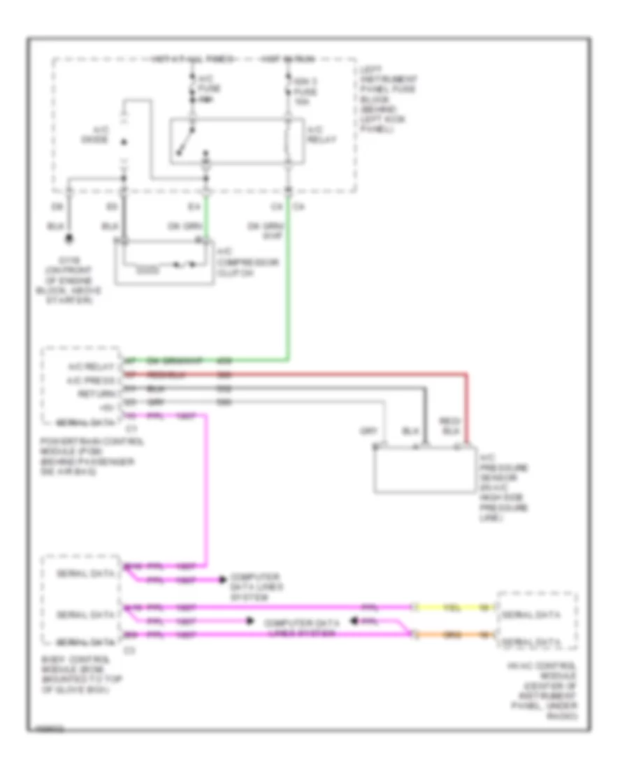
Compressor Wiring Diagram, with Auto A/C for Saturn L200 2003
List of elements for Compressor Wiring Diagram, with Auto A/C for Saturn L200 2003:
- +5v
- A/c
- A/c diode
- A/c fuse 10a
- A/c press
- A/c pressure sensor (in a/c high side pressure line)
- A/c relay
- A10
- B10
- Body control module (bcm) (mounted to top of glove box)
- Compressor clutch
- Computer data lines system
- G118 (on front of engine block, above starter)
- Hot at all times
- Hot in run
- Hvac control module (center of instrument panel, under radio)
- Ign 3 fuse 10a
- Left instrument panel fuse block (behind left kick panel)
- Powertrain control module (pcm) (behind passenger sie air bag)
- Return
- Serial data
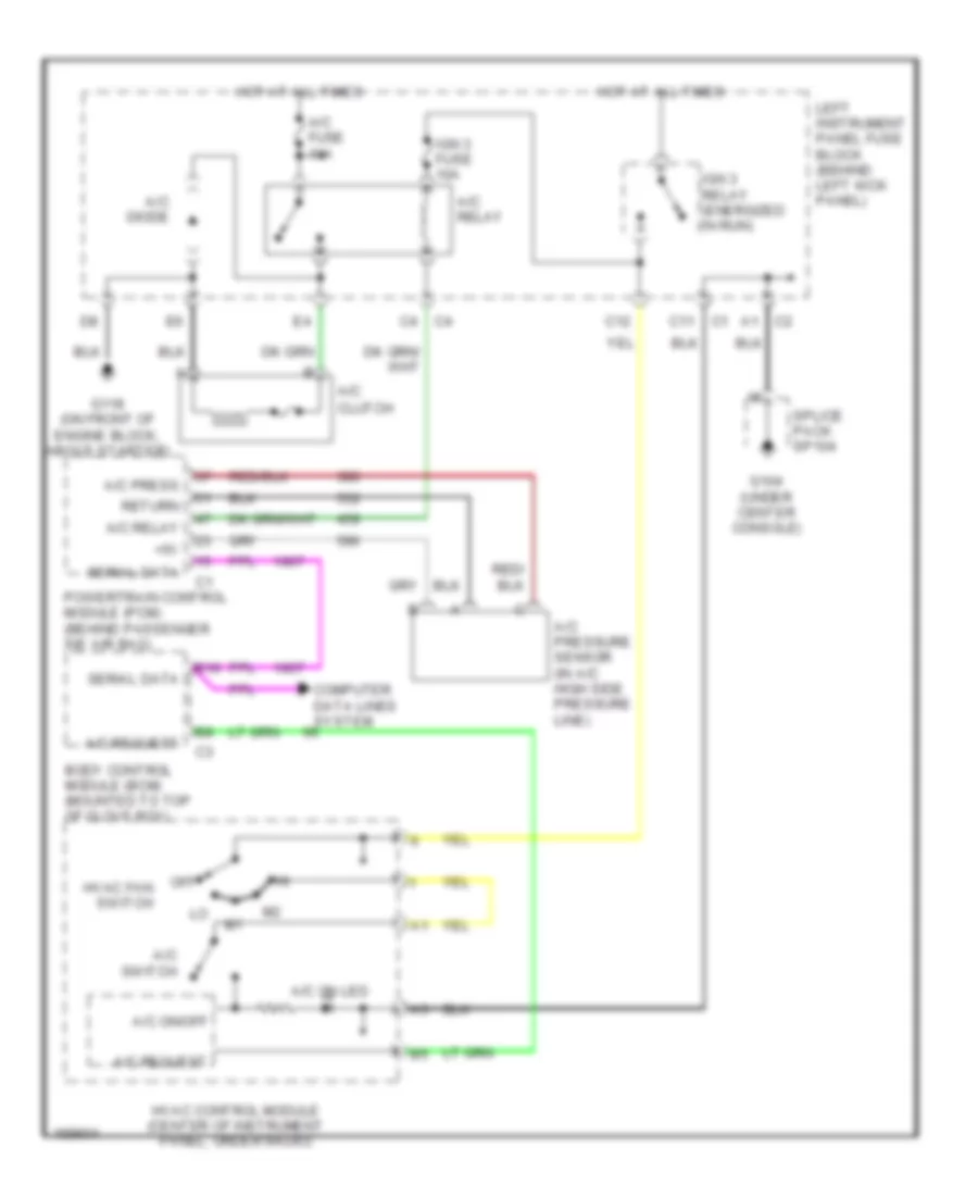
Compressor Wiring Diagram, with Manual A/C for Saturn L200 2003
List of elements for Compressor Wiring Diagram, with Manual A/C for Saturn L200 2003:
- +5v
- A/c
- A/c diode
- A/c fuse 10a
- A/c on led
- A/c on/off
- A/c press
- A/c pressure sensor (in a/c high side pressure line)
- A/c relay
- A/c request
- A/c switch
- B10
- Body control module (bcm) (mounted to top of glove box)
- C11
- C12
- Clutch
- Computer data lines system
- G104 (under center console)
- G118 (on front of engine block, above starter)
- Hot at all times
- Hvac control module (center of instrument panel, under radio)
- Hvac fan switch
- Ign 3 fuse 10a
- Ign 3 relay (energized in run)
- Left instrument panel fuse block (behind left kick panel)
- Off
- Powertrain control module (pcm) (behind passenger sie air bag)
- Return
- Serial data
- Splice pack sp104
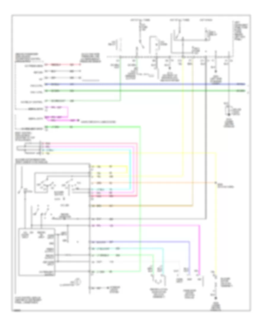
Manual A/C Wiring Diagram (1 of 2) for Saturn L200 2003
List of elements for Manual A/C Wiring Diagram (1 of 2) for Saturn L200 2003:
- (behind passenger side air bag) powertrain control module (pcm)
- (in a/c high side pressure line) a/c refrigerant pressure sensor
- +5v
- A/c comp- ressor clutch
- A/c diode
- A/c fuse 10a
- A/c led
- A/c on/off input
- A/c press sens
- A/c relay
- A/c relay control
- A/c request input
- A/c request output
- A/c switch
- A1 c2
- B10
- Blower motor (on hvac assembly)
- Blower motor resistors (right side of hvac module)
- Blower switch
- Body control module (bcm) (mounted to top of glove box)
- C11 c1
- C12
- Computer data lines system
- Def
- Def mode input
- Dim illumination
- Fan 1 ctrl
- Fan 2 ctrl
- Fresh output
- G104 (under center console)
- G118 (on front of engine block, above starter)
- G304 (left side of engine compt)
- G305 (under center console)
- Gnd
- Grd
- Hot at all times
- Hot in run
- Hvac control module (center of instrument panel, under radio)
- Ign
- Ign 3 fuse 10a
- Ign 3 relay
- Interior lights system
- Left instrument panel fuse block (lipfb) (behind left kick panel)
- Mode door motor (on hvac module)
- Mode input
- Off
- Pnk
- Recirc indicator
- Recirc on input
- Recirc output
- Recirculation door motor (on hvac assembly)
- Return
- S206 (in hvac harn)
- Serial data
- Splice pack sp104
- Vent
Manual A/C Wiring Diagram (2 of 2) for Saturn L200 2003
List of elements for Manual A/C Wiring Diagram (2 of 2) for Saturn L200 2003:
- A12
- Battery
- Cool fan low ref
- Cool fan mtr med spd
- Cool fan mtr voltage
- Coolant fan 1 fuse 30a
- Coolant fan 2 fuse 30a
- Cooling fan 1 (behind radiator)
- Cooling fan 2 (on front of a/c condenser)
- Cooling fan control module (near battery)
- F12
- G105 (left front of engine compt)
- Ground
- Hi spd cool fan sig
- Hot at all times
- Low spd cool fan sig
- Red
- Splice pack sp103
- Underhood fuse block (uhfb) (left side of engine compt)

 Čeština
 Dansk
Dansk Deutsch
 Ελληνικά
 English
 English
 Español
 Suomi
Suomi Français
 Français
 עברית
עברית Hrvatski
 Magyar
 Italiano
 日本語
日本語 한국어
한국어 Polski
 Português
 Português
 Română
 Русский
 Slovenčina
 Slovenščina
 Svenska
 Türkçe
 中文 (中国)