
 Čeština
 Dansk
Dansk Deutsch
 Ελληνικά
 English
 English
 Español
 Suomi
Suomi Français
 Français
 עברית
עברית Hrvatski
 Magyar
 Italiano
 日本語
日本語 한국어
한국어 Polski
 Português
 Português
 Română
 Русский
 Slovenčina
 Slovenščina
 Svenska
 Türkçe
 中文 (中国)

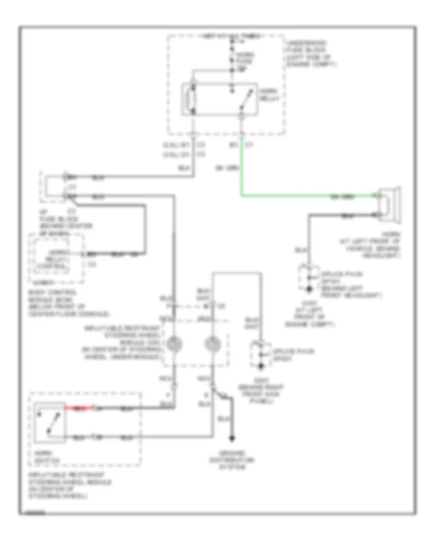
HORN
Horn Wiring Diagram for Saturn Vue Red Line 2004
List of elements for Horn Wiring Diagram for Saturn Vue Red Line 2004:

AIR CONDITIONINGANTI-LOCK BRAKESANTI-THEFTCOMPUTER DATA LINESBODY CONTROL MODULESCOOLING FANDEFOGGERSEXTERIOR LIGHTSCRUISE CONTROLELECTRONIC POWER STEERINGENGINE PERFORMANCEHORNGROUND DISTRIBUTIONINSTRUMENT CLUSTERPOWER MIRRORSHEADLIGHTSPOWER SEATSINTERIOR LIGHTSSHIFT INTERLOCKRADIOPOWER TOP/SUNROOFPOWER WINDOWSSTARTING/CHARGINGPOWER DISTRIBUTIONSUPPLEMENTAL RESTRAINTSWARNING SYSTEMSTRANSMISSIONWIPER/WASHER