INSTRUMENT CLUSTER
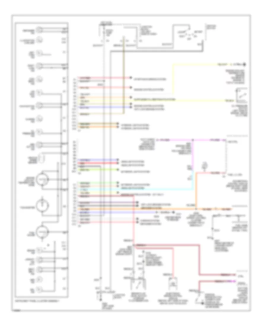
Instrument Cluster Wiring Diagram for Chevrolet Metro 1998
List of elements for Instrument Cluster Wiring Diagram for Chevrolet Metro 1998:
- (center rear of engine)
- (m/t only)
- 1.3l vin 9 only
- A10
- A11
- A12
- A13
- A14
- A15
- A16
- A16 c1
- Abs active ind
- Abs ind
- Accy
- Air bag ind
- Anti-lock brakes system
- B10
- B10 c2
- Brake fluid level switch (in brake fluid reservoir)
- Brake ind
- C1 b5
- C10
- C11
- C12
- C13
- C13 c3
- Charge ind
- Ctrl
- Data link connector (behind right side of dash)
- Daytime running lamps control module (behind left side of dash)
- Defogger ind
- Defogger system
- Drl ind
- Duty check
- Electronic brake control module (behind left side of dash, above junction block)
- Engine controls system
- Engine coolant temperature gage
- Engine coolant temperature sensor (on rear of engine, in t'stat housing)
- Exterior lights system
- Fuel gage sending unit (in fuel tank)
- Fuel gauge
- Fuel lvl sig
- G100 (lh front engine compt, on lh front inner fender, near battery)
- G131
- G202 (left side of dash)
- G407 (rear center of luggage compt, near deck lid striker)
- Headlights system
- High beam ind
- Hot in on and start
- Ig-coil fuse 15a
- Ignition switch
- Illumination (2 bulbs)
- Ind ctrl
- Instrument panel cluster assembly
- Interior lights system
- Junction block
- Junction block (on left side of dash)
- Left turn ind
- Lock
- Malfunction ind
- Off
- Oil pressure ind
- Oil pressure switch (left side of engine, above oil filter)
- Parking brake switch (under floor console, on parking brake lever base)
- Powertrain control module (behind right side of dash, near glove box)
- Red
- Right turn ind
- S213
- S223 (main harn, left rear of engine compt)
- S226 (dash harn, approx 2cm from cluster connector c3 breakout)
- S240
- S242
- S245
- S261 (engine harn, 4cm from pcm connectors breakout)
- S315
- Seat belt ind
- Signal
- Start
- Starting/charging system
- Tachometer
- Upshift ind (m/t)
- Vehicle speed sensor
- Warning system
 Čeština
 Dansk
Dansk Deutsch
 Ελληνικά
 English
 English
 Español
 Suomi
Suomi Français
 Français
 עברית
עברית Hrvatski
 Magyar
 Italiano
 日本語
日本語 한국어
한국어 Polski
 Português
 Português
 Română
 Русский
 Slovenčina
 Slovenščina
 Svenska
 Türkçe
 中文 (中国)
 Nederlands