POWER DISTRIBUTION
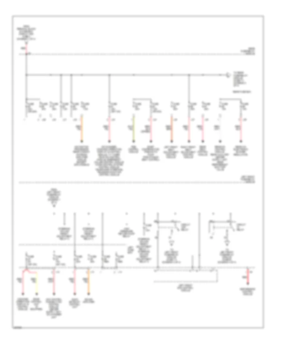
Power Distribution Wiring Diagram (1 of 4) for Mercedes-Benz S500 2005
 https://portal-diagnostov.com/license.html
Automotive Electricians Portal FZCO
Automotive Electricians Portal FZCO
https://portal-diagnostov.com/license.html
https://portal-diagnostov.com/license.html
Automotive Electricians Portal FZCO
Automotive Electricians Portal FZCO
List of elements for Power Distribution Wiring Diagram (1 of 4) for Mercedes-Benz S500 2005:
- A/c system blower unit
- Air pump relay
- Air suspension relay
- Airmatic w/ ads control module
- Battery
- Engine electronic/ chassis relay
- Engine/ climate control electric cooling fan
- Fanfare relay
- Fuse (res or 30a)
- Fuse (res)
- Fuse 100a
- Fuse 150a
- Fuse 15a
- Fuse 20a
- Fuse 30a
- Fuse 40a
- Fuse 5a
- Fuse 60a
- Generator
- L16
- L19
- L21
- L22
- Left front door control module
- Left front fuse/relay module
- Left fuse box
- Mr1
- Red
- Right front door control module
- Right front fuse/relay module
- Right front sam control module
- Right fuse box
- Starter
- Steering column longitudinal adjustment relay 1
- Steering column longitudinal adjustment relay 1, steering column longitudinal adjustment relay 2
- Steering column longitudinal adjustment relay 2
- Terminal block & fuse box (circuit 30 & 61)
- Terminal block & fuse box (circuit 30z)
- To cockpit fuse box (fuse 78) (diagram 4 of 4)
- To cockpit fuse box (fuse 80) (diagram 4 of 4)
- To electronic ignition- starter control module (diagram 4 of 4)
- To left front fuse/relay module (fuse 23) (diagram 2 of 4)
- To rear fuse/relay module (fuse 55) (diagram 2 of 4)
- W10 (right rear side of trunk)
- Windshield heater relay
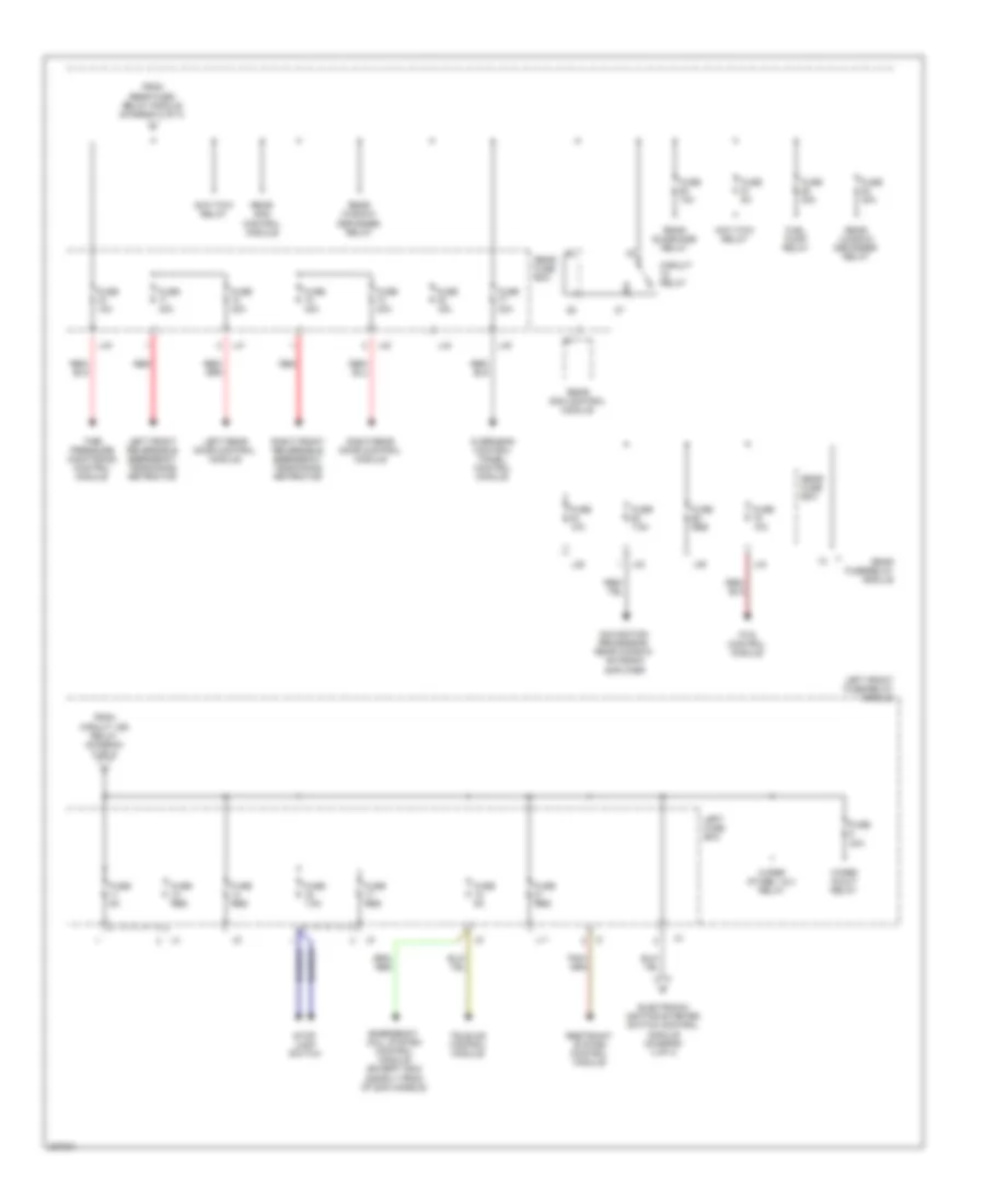
Power Distribution Wiring Diagram (2 of 4) for Mercedes-Benz S500 2005
List of elements for Power Distribution Wiring Diagram (2 of 4) for Mercedes-Benz S500 2005:
- (or 15a)
- (or 7.5a)
- Audio gateway control unit
- Cd changer, command operating display & control module, tv tuner, tele aid control module, emergency called control module voice control system control module, telephone interface, telecommunication control module
- Circuit 15r relay
- Circuit relay
- Command operating display & control module,
- E-net compensator, pneumatic pump (for dynamic seat control)
- Esp/sps/bas control module
- From left front fuse/relay module (diagram 1 of 4)
- From terminal block & fuse box (circuit 30z) fuse 2 (diagram 1 of 4)
- Fuse 10a
- Fuse 15a
- Fuse 15a (or 7.5a)
- Fuse 20a
- Fuse 25a
- Fuse 30a
- Fuse 30a (or 25a)
- Fuse 5a
- Fuse 7.5a
- Fuse 7.5a (or 30a)
- Fuse res
- High pressure return pump relay
- L12
- L13
- L14
- L29
- L30
- L31
- L32
- L33
- L34
- L35
- L37
- L38
- L39
- Left front fuse/relay module
- Left front sam control module
- Left front seat adjustment control module
- Left fuse box
- Navigation processor, rear window antenna amplifier module (except 2003 models)
- Pse control module
- Rear a/c electronic blower regulator,
- Rear fuse box
- Rear fuse/relay module
- Rear seat control module
- Red
- Right front seat adjustment control module
- Sdar control unit (if equipped)
- Sound amplifier
- Steering column height adjustment relay 1, steering column height adjustment relay 2
- Steering column height adjustment relay 2
- To left front fuse/relay module (fuse 11) (diagram 3 of 4)
- To left front fuse/relay module (fuse 6) (diagram 4 of 4)
- To rear fuse/relay module (fuse 71) (diagram 3 of 4)
Power Distribution Wiring Diagram (3 of 4) for Mercedes-Benz S500 2005
List of elements for Power Distribution Wiring Diagram (3 of 4) for Mercedes-Benz S500 2005:
- Anti-tow relay
- Circuit relay
- Electronic ignition-starter switch control module (diagram 4 of 4)
- Emergency call system control module (except 2003 & early prod of 2004 models)
- From circuit 15r relay (diagram 2 of 4)
- From rear fuse/ relay module (diagram 2 of 4)
- Fuel pump relay
- Fuse 10a
- Fuse 15a
- Fuse 30a
- Fuse 40a
- Fuse 5a
- Fuse 7.5a
- Fuse res
- L11
- L28
- L33
- L36
- L40
- L41
- L42
- L43
- L44
- L45
- Left front fuse/relay module
- Left front reversible emergency tensioning retractor
- Left fuse box
- Left rear door control module
- Navigation processor, rear window antenna amplifier
- Overhead control panel control module
- Pts control module
- Rear fuse box
- Rear fuse/relay module
- Rear sam control module
- Rear sunshade relay
- Rear window defogger relay
- Red
- Restraint system control module
- Right front reversible emergency tensioning retractor
- Right rear door control module
- Stop lamp switch
- Tele-aid control module
- Tire pressure monitoring control module
- Wiper in/out relay
- Wiper stage 1 & 2 relay
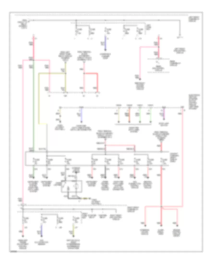
Power Distribution Wiring Diagram (4 of 4) for Mercedes-Benz S500 2005
List of elements for Power Distribution Wiring Diagram (4 of 4) for Mercedes-Benz S500 2005:
- 15r
- 30z
- 78a
- 79a
- 80a
- 81a
- 82a
- 83a
- 84a
- 85a
- 86a
- Aac multifunction sensor
- Acc pushbutton control module
- Alarm signal horn
- Bls
- Can-b h
- Can-b l
- Can-c h
- Can-c l
- Central gateway control module
- Cigar lighter
- Cockpit fuse box (right side of dash)
- Computer data lines system
- Computer data lines system (data link connector)
- Diag
- Electronic ignition- starter switch control module (left side of dash)
- Engine control module (me-sfi)
- Fanfare relay
- From e circuit 15 relay (diagram 2 of 4)
- From left front fuse/ relay module (diagram 3 of 4)
- From terminal block & fuse box (circuit 30 & 61) (diagram 1 of 4)
- From terminal block & fuse box (circuit 30z) (diagram 1 of 4)
- Fuse 10a
- Fuse 15a
- Fuse 5a
- Fuse 7.5a
- Fuse res
- Headlamp range adjustment control module
- Ignition coils, radio interference suppression capacitors
- Instrument cluster system
- Instrument cluster system, computer data lines system
- Interior lights system
- L10
- L20
- L26
- L27
- Left front fuse/relay module
- Left front sam control module
- Left fuse box
- Nca
- Pnk/ red
- Rear fuse/relay module
- Rear sam control module
- Red
- Restraint system control module
- Right front fuse/relay module
- Right front sam control module
- Right fuse box
- Starter relay
- Steering column module
- Stop lamp switch
- Upper control panel control module
- W36/2 (at right footwell)
- Windshield washer pump

 Čeština
 Dansk
Dansk Deutsch
 Ελληνικά
 English
 English
 Español
 Suomi
Suomi Français
 Français
 עברית
עברית Hrvatski
 Magyar
 Italiano
 日本語
日本語 한국어
한국어 Polski
 Português
 Português
 Română
 Русский
 Slovenčina
 Slovenščina
 Svenska
 Türkçe
 中文 (中国)