SHIFT INTERLOCK
Reverse Lockout Wiring Diagram for Volvo V50 T-5 R-Design 2011
 https://portal-diagnostov.com/license.html
Automotive Electricians Portal FZCO
Automotive Electricians Portal FZCO
https://portal-diagnostov.com/license.html
https://portal-diagnostov.com/license.html
Automotive Electricians Portal FZCO
Automotive Electricians Portal FZCO
List of elements for Reverse Lockout Wiring Diagram for Volvo V50 T-5 R-Design 2011:
- Central electronic module (cem) (behind right side of dash)
- Engine compartment distribution box (left side of engine compt)
- Fuse 60a
- G10 (base of right "a" pillar)
- Hot at all times
- Reverse interlock solenoid (at base of shift lever assembly)
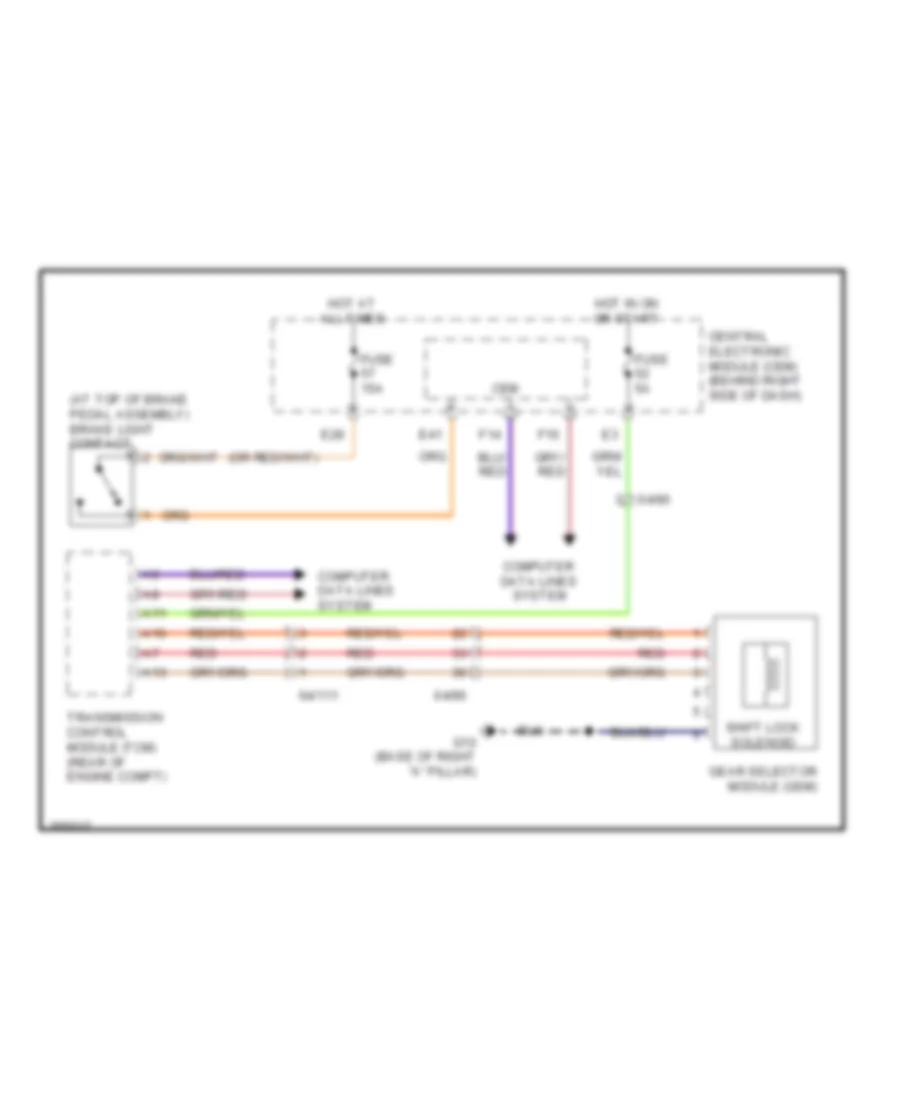
Shift Interlock Wiring Diagram for Volvo V50 T-5 R-Design 2011
List of elements for Shift Interlock Wiring Diagram for Volvo V50 T-5 R-Design 2011:
- (at top of brake pedal assembly) brake light contact
- 64/111
- 64/90
- A11
- A13
- A16
- Cem
- Central electronic module (cem) (behind right side of dash)
- Computer data lines system
- E28
- E41
- F14
- F16
- Fuse 15a
- Fuse 5a
- G10 (base of right "a" pillar)
- Gear selector module (gsm)
- Hot at all times
- Hot in on or start
- Red
- Shift lock solenoid
- Transmission control module (tcm) (rear of engine compt)

 Čeština
 Dansk
Dansk Deutsch
 Ελληνικά
 English
 English
 Español
 Suomi
Suomi Français
 Français
 עברית
עברית Hrvatski
 Magyar
 Italiano
 日本語
日本語 한국어
한국어 Polski
 Português
 Português
 Română
 Русский
 Slovenčina
 Slovenščina
 Svenska
 Türkçe
 中文 (中国)