SUPPLEMENTAL RESTRAINTS
Supplemental Restraint Wiring Diagram for Chevrolet Cutaway G3500 1999
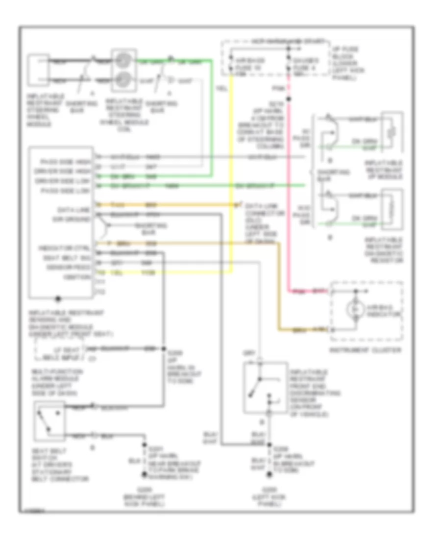
List of elements for Supplemental Restraint Wiring Diagram for Chevrolet Cutaway G3500 1999:
- A16
- Air bag indicator
- Air bags fuse 10 10a
- B nca
- B17
- Bar
- Data line
- Data link connector (dlc) (under left side of dash)
- Driver side high
- Driver side low
- G200 (behind left kick panel)
- G200 (left kick panel)
- Gauges fuse 4 10a
- Hot in run and start
- I/p fuse block (lower left kick panel)
- Ignition
- Indicator ctrl
- Inflatable restraint diagnostic resistor
- Inflatable restraint front end discriminating sensor (on front of vehicle)
- Inflatable restraint i/p module
- Inflatable restraint sensing and diagnostic module (under left front seat)
- Inflatable restraint steering wheel module
- Inflatable restraint steering wheel module coil
- Instrument cluster
- Lf seat belt input
- Multi-function alarm module (under left side of dash)
- Nca
- Pass side high
- Pass side low
- Pnk
- S201 (i/p harn, near breakout to park brake warning sw)
- S208 (i/p harn, in breakout to sdm)
- S209 (i/p harn, in breakout to sdm)
- S216 (i/p harn, 4 cm from breakout to conn at base of steerning column)
- Seat belt sig
- Seat belt switch (at driver's stationary belt connector
- Sensor feed
- Shorting
- Shorting bar
- Sir ground
- Tan
- W/ pass sir
- W/o pass sir
 Čeština
 Dansk
Dansk Deutsch
 Ελληνικά
 English
 English
 Español
 Suomi
Suomi Français
 Français
 עברית
עברית Hrvatski
 Magyar
 Italiano
 日本語
日本語 한국어
한국어 Polski
 Português
 Português
 Română
 Русский
 Slovenčina
 Slovenščina
 Svenska
 Türkçe
 中文 (中国)
 Nederlands