ANTI-LOCK BRAKES
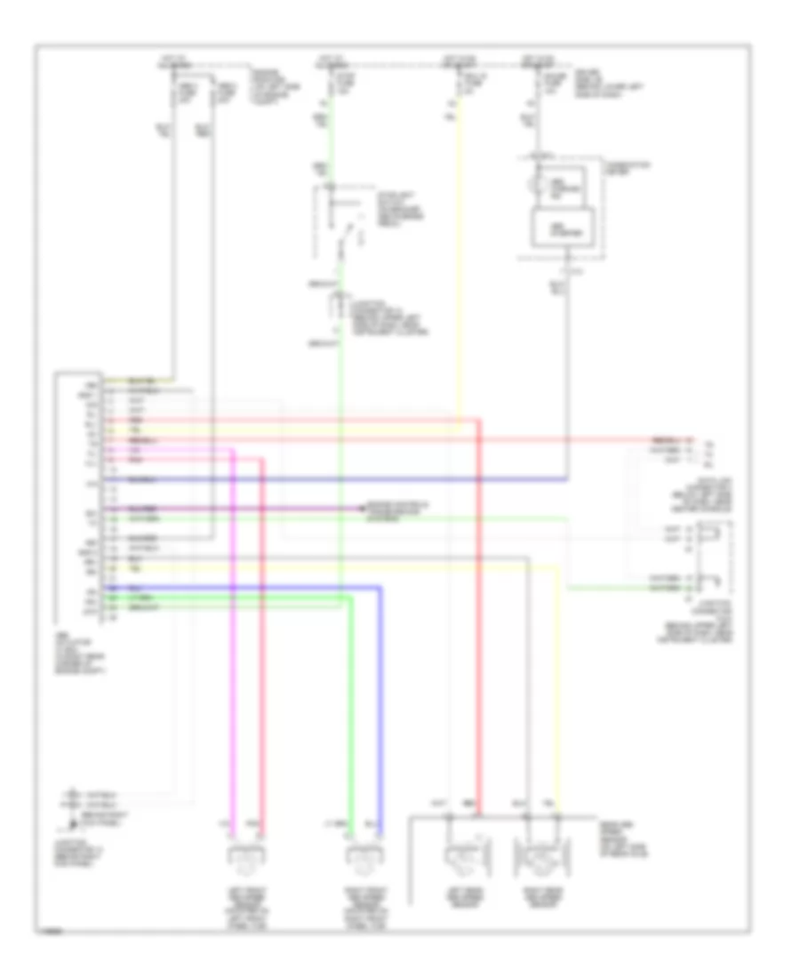
Anti-lock Brakes Wiring Diagram for Toyota Tundra Limited 2003
List of elements for Anti-lock Brakes Wiring Diagram for Toyota Tundra Limited 2003:
- (behind right kick panel) ii
- +bm
- +bs
- Abs 2 fuse 40a
- Abs 3 fuse 40a
- Abs actuator w/ ecu (in right rear corner of engine compt)
- Abs inverter
- Abs warning ind
- C11
- C13
- Combination meter
- D/g
- Data link connector 3 (below left side of dash, near center console)
- Driver side j/b (behind lower left side of dash)
- Ecu ig fuse 5a
- Engine controls, transmissions systems
- Engine room r/b (on left side of engine compt)
- Exi
- Fl+
- Fl-
- Fr+
- Fr-
- Gauge fuse 10a
- Gnd 1
- Gnd 2
- Hot at all times
- Hot in on or start
- Ig1
- Junction connector 10 (behind upper left side of dash, near instrument cluster)
- Junction connector 13 (behind right kick panel)
- Junction connector 5 & 8 (behind upper left side of dash, near instrument cluster)
- Left front abs speed sensor (mounted on left front wheel hub)
- Left rear abs speed sensor
- Pnk
- Rear abs speed sensor (on left side of rear axle)
- Red
- Right front abs speed sensor (mounted on right front wheel hub)
- Right rear abs speed sensor
- Rl+
- Rl-
- Rr+
- Rr-
- Sil
- Stop fuse 15a
- Stoplight switch (on bracket, above brake pedal)
- Stp
 Čeština
 Dansk
Dansk Deutsch
 Ελληνικά
 English
 English
 Español
 Suomi
Suomi Français
 Français
 עברית
עברית Hrvatski
 Magyar
 Italiano
 日本語
日本語 한국어
한국어 Polski
 Português
 Português
 Română
 Русский
 Slovenčina
 Slovenščina
 Svenska
 Türkçe
 中文 (中国)
 Nederlands