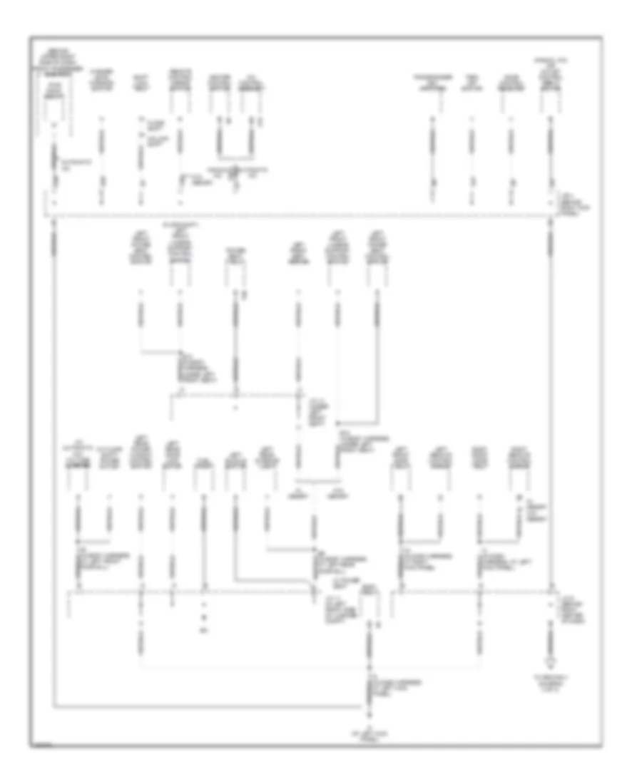
GROUND DISTRIBUTION
Ground Distribution Wiring Diagram (1 of 4) for Toyota Avalon XL 2004
 https://portal-diagnostov.com/license.html
Automotive Electricians Portal FZCO
Automotive Electricians Portal FZCO
https://portal-diagnostov.com/license.html
https://portal-diagnostov.com/license.html
Automotive Electricians Portal FZCO
Automotive Electricians Portal FZCO
List of elements for Ground Distribution Wiring Diagram (1 of 4) for Toyota Avalon XL 2004:
- (in dash harness, at center of dash) i12
- (in dash harness, at right side of dash) i14
- (on left front inner fender panel) engine room j/b
- (on left front of engine compt) engine room r/b 3
- (on left inner fender panel) engine room r/b 5
- (w/o traction control) active light relay
- 6 spkr
- 7 spkr
- A/c dual pressure switch
- A/c single pressure switch
- A/f relay
- Abs & ba & trac & vsc actuator
- Abs actuator & ecu
- Abs sol relay
- Abs speed sensor shields
- B12 (in body harness, under left front seat)
- Brake fluid level warning switch
- C10
- Combination meter
- Data link connector
- E4 (in engine harness, at front of engine)
- E6 (at left front of engine)
- Eb (at left front of engine, on surge tank)
- Ec (at left front of engine, on surge tank)
- Ed (at front of left front fender)
- Ee (at front of left front fender)
- Efi relay
- Engine control module
- Engine hood courtesy switch
- F10
- Fan 2 relay
- Heated oxygen sensor (bank 1 sensor 2)
- Heated oxygen sensor shield
- Htr relay
- I22 (in dash harness, at right kick panel)
- I23 (in dash harness, at right kick panel)
- Idle air control valve
- Ig2 relay
- Ignition coil & igniter
- Ih (at right center of dash)
- J/c 1 (on top of left kick panel)
- J/c 14 (w/ memory) (under left front seat)
- J/c 3 (behind right center of dash)
- J/c 5 (behind right side of dash)
- J/c 7 (behind right side of dash)
- Left front
- Left front fog light
- Left front power seat front vertical position sensor
- Left front power seat rear vertical position sensor
- Left front power seat reclining position sensor
- Left front power seat slide position sensor
- Left front turn signal/ parking light
- Left low headlight
- Left rear
- M10
- Multi display
- Multi- display (w/ navigation)
- Nca
- P21
- Power seat ecu
- Radiator fan motor
- Radio & player
- Right front
- Right rear
- St relay
- To j/c 7 (diagram 4 of 4)
- W/ immobilizer system
- W/ traction control
- W/o traction control
- Water temperature switch 1
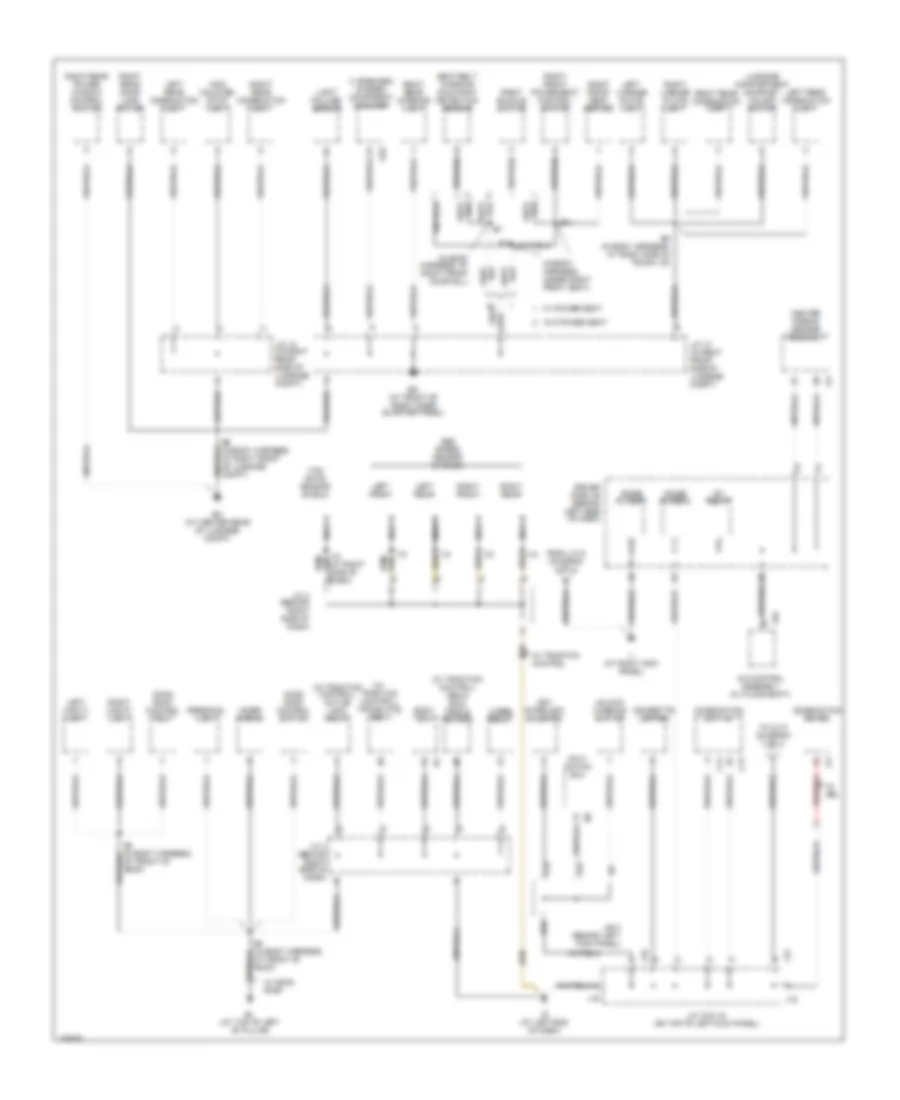
Ground Distribution Wiring Diagram (2 of 4) for Toyota Avalon XL 2004
List of elements for Ground Distribution Wiring Diagram (2 of 4) for Toyota Avalon XL 2004:
- (behind upper right side of dash) front passenger side r/b 7
- (floor shift) left front lumbar support control switch
- (manual a/c) air outlet control servo motor
- (w/ automatic a/c) voltage inverter
- (w/ floor shift) power outlet
- A/c control assembly
- A15
- Automatic a/c
- B1 (in body harness, at left front door sill)
- B12 (in body harness, under left front seat)
- B6 (in body harness, at left rear door sill)
- Body ecu
- C20
- Column shift
- D20
- D21
- Door control receiver
- F20
- Floor shift
- Fuel pump
- Heater control switch
- I21 (in dash harness, at right kick panel)
- I3 (in dash harness, at left kick panel)
- I5 (in dash harness, at left kick panel)
- If (at left kick panel)
- J/b 4 (behind right kick panel)
- J/c 11 (in left front side of luggage compt)
- J/c 14 (under left front seat)
- J/c 6 (behind right center of dash)
- Left buckle switch
- Left front door ecu
- Left front lumbar support control switch
- Left front power seat control switch
- Left front seat heater
- Left rear door lock motor
- Left rear interior light
- Left rear power window control switch
- Left remote control mirror
- Manual a/c
- P20
- Power seat ecu
- Pwr point relay
- Remote control mirror switch
- Right front door ecu
- Right remote control mirror
- Shift lock ecu
- To ground ii (diagram 3 of 4)
- Trac off switch
- Transponder key amplifier
- W/ memory
- W/ power seat
- W/o memory
- Washer level warning switch
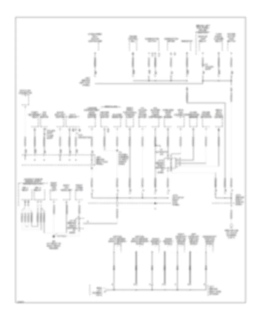
Ground Distribution Wiring Diagram (3 of 4) for Toyota Avalon XL 2004
List of elements for Ground Distribution Wiring Diagram (3 of 4) for Toyota Avalon XL 2004:
- (7 speaker) stereo component amplifier
- (in body harness, at right front door sill)
- (in body harness, under right front seat)
- (w/ traction control) abs & ba & trac & vsc ecu
- (w/ traction control) active light relay
- (w/ traction control) translate ecu
- A/c control assembly (w/ floor shift)
- A16
- Abs speed sensor shields
- B14
- B15
- B4 (in body harness, at front of roof)
- B8 (in body harness, at right side of trunk lid)
- B9 (in body harness, at right front of luggage compt)
- Bl (at top of left "b" pillar)
- Bm (at center rear of luggage compt)
- Bn (at front of right inner quarter panel)
- Body ecu
- C13
- C14
- C22
- Center airbag sensor assembly
- Cigarette lighter
- Combination meter
- Combination switch
- D22
- Driver side j/b (behind left side of dash)
- E22
- From j/c 6 (diagram 2 of 4)
- High mounted stop light
- I15
- I15 (at right side of dash)
- Ig (at left end of dash)
- Ig1 relay
- Ii (at right kick panel)
- Inner mirror
- J/b 3 (behind left kick panel)
- J/c 10 (in right front side of luggage compt)
- J/c 12 (in right rear side of luggage compt)
- J/c 15 & 16 (on top of left kick panel)
- J/c 4 (behind right side of dash)
- J/c 4 (behind right side of dash) b
- J15
- J16
- Key interlock solenoid
- Left front
- Left license plate light
- Left rear
- Left rear combination light
- Left vanity light
- Light failure sensor
- Luggage compartment door key unlock switch
- Moon roof control ecu
- Moon roof control switch
- Navi- gation ecu
- Nca
- Noise filter 1
- Noise filter 2
- Personal light
- Right buckle switch
- Right front
- Right front power seat control switch
- Right front seat heater
- Right license plate light
- Right rear
- Right rear combination light
- Right rear door lock motor
- Right rear interior light
- Right rear power window control switch
- Right vanity light
- S10
- Seat belt warning occupant detection sensor
- To j/c 5 (diagram 4 of 4)
- Unlock warning switch
- W/ drl
- W/ moon roof
- W/ power seat
- W/ traction control
- W/o power seat
- Wiper relay
- Yaw rate sensor shield
Ground Distribution Wiring Diagram (4 of 4) for Toyota Avalon XL 2004
List of elements for Ground Distribution Wiring Diagram (4 of 4) for Toyota Avalon XL 2004:
- (behind left kick panel) driver side r/b 6
- (if equipped) navi- gation controller
- (on right side of engine compt) engine room r/b 2
- (w/ column shift) power outlet
- A/c blower motor linear controller
- A20
- A21
- Abs & ba & trac & vsc ecu
- Air fuel ratio sensor (bank1 sensor1) shield
- Air fuel ratio sensor (bank2 sensor1) shield
- B20
- B21
- Back-up lamp relay
- Blower resistor
- C11
- C12
- Column shift
- Combination meter
- Combination switch
- Crankshaft position sensor shield
- Cruise control actuator
- Cruise control ecu
- Data link connector
- Drl 3 relay
- Drl 4 relay
- Ea (at front of right front fender)
- Floor shift
- From j/c 7 (diagram 1 of 4)
- From splice j/c 15 & 16 (diagram 3 of 4)
- Front wiper motor
- G20
- Glass breakage sensor
- Glove box light switch
- H10
- H20
- Heater control switch
- I13 (in dash harness, at right side of dash)
- J/b 3 (behind left kick panel)
- J/b 4 (behind right kick panel)
- J/c 18 (behind right center of dash)
- J/c 19 (behind right center of dash)
- J/c 5 (behind right side of dash)
- J/c 7 (behind right side of dash)
- J/c 9 (on top of right kick panel)
- Knock sensor 1 shield
- Knock sensor 2 shield
- Left camshaft position sensor shield
- Luggage compartment door opener switch
- Manual a/c
- Multi display
- Nca
- O/d main switch
- Power outlet main switch
- Rheostat
- Right camshaft position sensor shield
- Right front fog light
- Right front turn signal/ parking light
- Right low headlight
- Theft deterrent ecu
- Turn signal flasher relay
- W/ automatic a/c
- W/ column shift
- W/o navigation
- Wireless door lock buzzer

 Čeština
 Dansk
Dansk Deutsch
 Ελληνικά
 English
 English
 Español
 Suomi
Suomi Français
 Français
 עברית
עברית Hrvatski
 Magyar
 Italiano
 日本語
日本語 한국어
한국어 Polski
 Português
 Português
 Română
 Русский
 Slovenčina
 Slovenščina
 Svenska
 Türkçe
 中文 (中国)