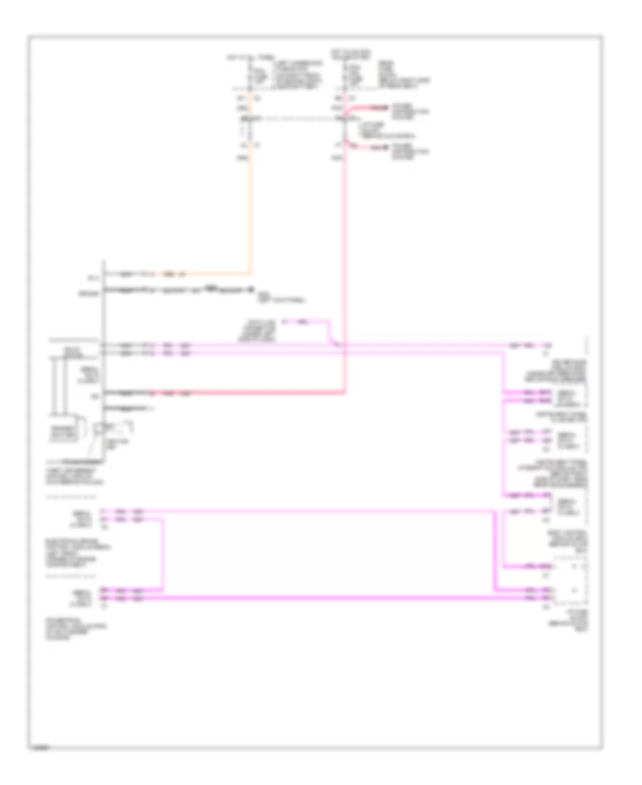
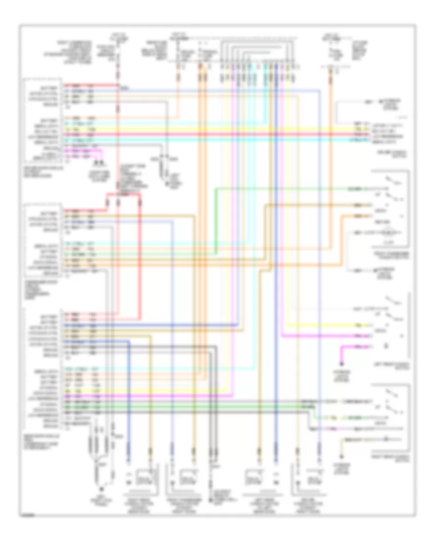
AIR CONDITIONING
Automatic A/C Wiring Diagram (1 of 3) for Buick Park Avenue 2005
 https://portal-diagnostov.com/license.html
Automotive Electricians Portal FZCO
Automotive Electricians Portal FZCO
https://portal-diagnostov.com/license.html
https://portal-diagnostov.com/license.html
Automotive Electricians Portal FZCO
Automotive Electricians Portal FZCO
List of elements for Automatic A/C Wiring Diagram (1 of 3) for Buick Park Avenue 2005:
- 5 volt ref
- A10
- A11
- A12
- Amb temp sig
- Ambient air temperature sensor (on center front of engine compt, on hood latch brace)
- B10
- B11
- B12
- Bat pos volt
- Blower spd ctrl
- C10
- C11
- C12
- C13
- C14
- C15
- C16
- Class 2 serial
- Clock sig
- Computer data lines system
- Cstr/ sbm fuse 10a
- D10
- D11
- D12
- D13
- D14
- D15
- D16
- Data sig
- G202 (left kick panel)
- Gnd
- Ground
- Hot at all times
- Hot in run
- Hvac control module
- Hvac fuse 10a
- I/p fuse block (behind glove box)
- Ign 3 volt
- Inside air temperature sensor (under left side of dash, near left center a/c vent)
- Inside temp sig
- Instrument panel integration module (ipm) (behind right side of dash, near rear of glove box)
- Interior lights system
- Lamp volt
- Left sun load sensor (on left side of dash, in defroster grille)
- Lft dr pos sig
- Lft solar sens
- Lft temp dr ctrl
- Ll temp sig
- Low ref
- Low rt temp sig
- Lower left air temperature sensor (on left side of dash, above sound insulator panel)
- Lower right air temperature sensor (on right side of dash, above sound insulator panel)
- Mode door ctrl
- Mode dr pos sig
- Nca
- Pass solar sens
- Recirc door ctrl
- Recirc dr pos sig
- Red
- Right air temperature switch assembly
- Right sun load sensor (on right side of dash, in defroster grille)
- Rt dr pos sig
- Rt temp dr ctrl
- Rt temp sig
- S213 (in dash harness, 44 cm from hvac control)
- S214 (in dash harness, 13 cm before i/p control module)
- Serial data
- Tan
- Up lft temp sig
- Up rt temp sig
- Upper left air temperature sensor (on left side of dash, near a/c vent)
- Upper right air temperature sensor (on right side of dash, near a/c vent)
- Vf dim sig
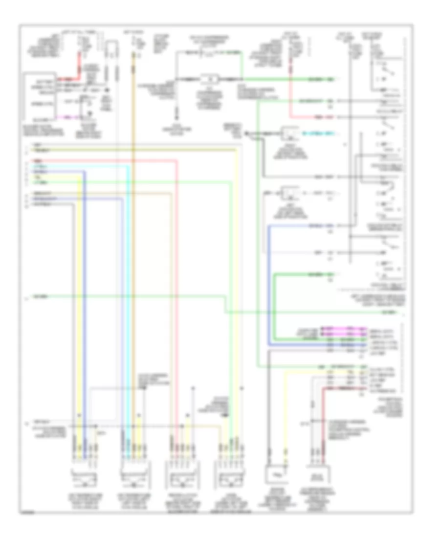
Automatic A/C Wiring Diagram (2 of 3) for Buick Park Avenue 2005
List of elements for Automatic A/C Wiring Diagram (2 of 3) for Buick Park Avenue 2005:
- (beneath battery tray) g105
- (hvac harness, 29 cm from mode actuator) s278
- (in body harness, 35 cm from g201)
- (in engine harness, 4 cm from powertrain control module harness breakout)
- (in hvac harness, 35.5 cm from mode actuator)
- (in hvac harness, 50.5 cm from mode actuator) s275
- (on a/c compressor) a/c compressor clutch
- 5v ref
- 87a
- A/c clu fuse 10a
- A/c clu relay
- A/c compressor clutch diode (near a/c compressor, in harness)
- A/c fuse 10a
- A/c press sig
- A/c refrigerant pressure sensor (near a/c compressor, on hose assembly)
- A10
- Air temperature actuator (left) (left side of hvac module)
- Air temperature actuator (right) (right side of hvac module)
- Battery
- Blo mot fuse 30a
- Blower motor (behind right side of dash)
- Blower motor control processor (near blower motor)
- Blower v+
- Clu rly ctrl
- Computer data lines system
- Cool- fan 1 fuse 30a
- Cool- fan 2 fuse 30a
- Coolfan 1 relay (low speed)
- Coolfan 2 relay (high speed)
- Coolfan s/p relay (series/parallel)
- D11
- E10
- Ect sens sig
- Engine coolant temperature (ect) sensor (under thermostat housing)
- F11
- G102 (near starter
- G201 (right kick panel)
- Ground
- H spd rly ctrl
- Hot at all times
- Hot in run
- Hot in run or start
- I/p fuse block (behind glove box)
- L spd rly ctrl
- Left cooling fan (on left rear side of radiator)
- Left underhood fuse block (on right front of engine compt, near battery)
- Low ref
- Mode actuator (under left side of dash, on left side of hvac module)
- Motor)
- Nca
- Powertrain control module (pcm) (in air cleaner housing)
- Recirculation actuator (behind right side of dash, right of blower motor)
- Red
- Right cooling fan (on right rear side of radiator)
- Right underhood fuse block (on right front of engine compt, forward of strut tower)
- S106 (in engine harness, 18 cm from a/c compressor clutch)
- S107 (in engine harness, 23 cm from a/c compressor clutch)
- S115
- S208
- S274
- Serial data
- Solid state
- Speed ctrl
Automatic A/C Wiring Diagram (3 of 3) for Buick Park Avenue 2005
List of elements for Automatic A/C Wiring Diagram (3 of 3) for Buick Park Avenue 2005:
- B10
- B12
- C1 f5
- C271
- C276
- Cd changer remote playback device
- Comfort serial data
- Computer data lines system
- F8 c4
- Hot w/ rap relay energized
- I/p fuse block (behind glove box)
- Inflatable restraint steering wheel module coil (top of steering column)
- Interior lights system
- Left steering wheel controls
- Nca
- Power distribution system
- Radio
- Rdo/ph fuse 5a
- Rear fuse block (below right side of rear seat)
- Remote radio ctrl sig
- Right steering wheel controls
- Serial data e&c
- Steering column fuse holder (at base of steering column)
- Sw 1
- Sw 2
- Sw 3
- Sw 4
- Sw 5
- Sw 6
- Sw 7
- Sw 8
- Switch fuse 2a
- Vehicle interface unit (on right front of trunk, attached to seat back brace)
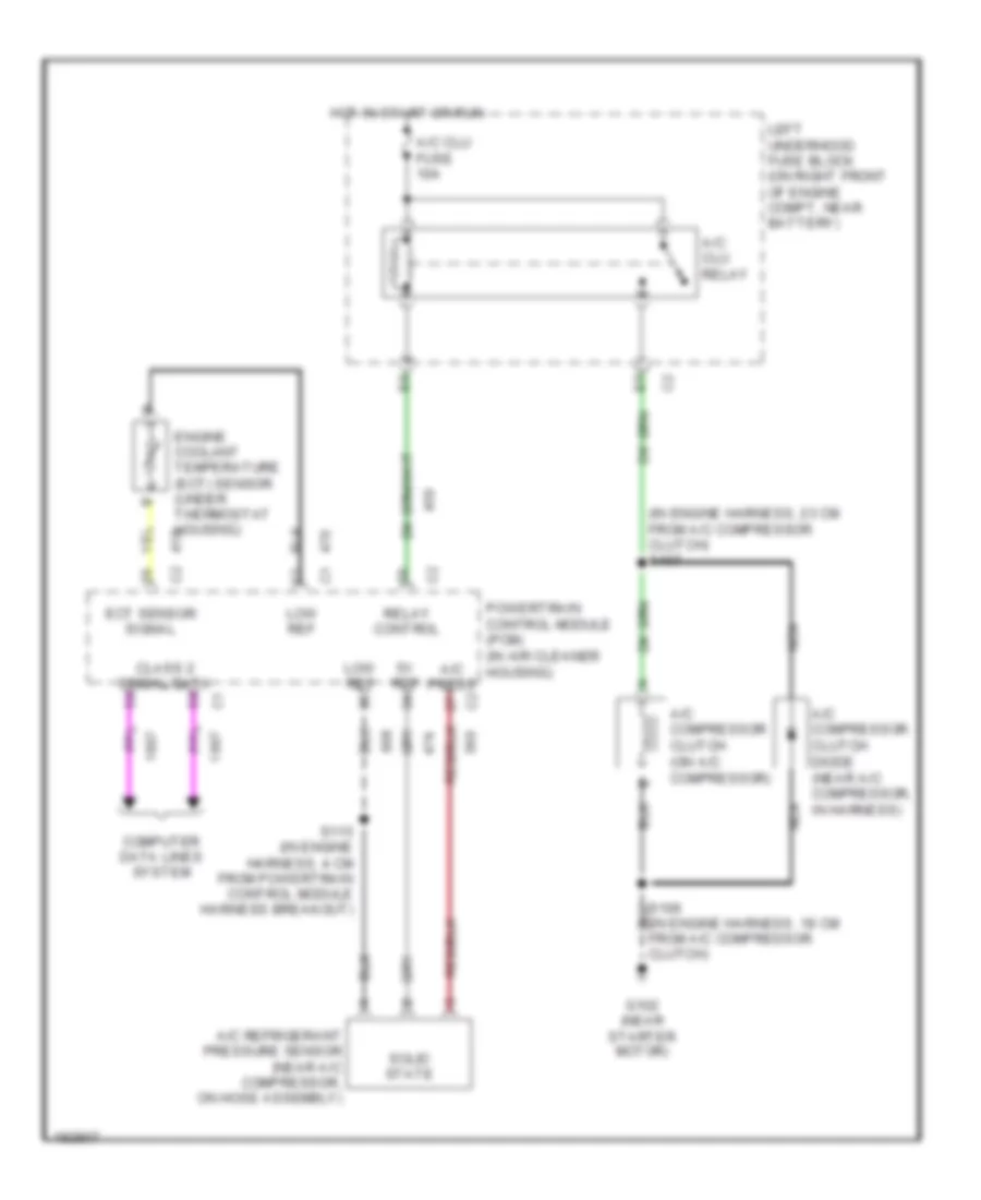
Compressor Wiring Diagram for Buick Park Avenue 2005
List of elements for Compressor Wiring Diagram for Buick Park Avenue 2005:
- (in engine harness, 18 cm from a/c compressor clutch)
- (in engine harness, 23 cm from a/c compressor clutch) s107
- 5v ref
- A/c clu fuse 10a
- A/c clu relay
- A/c compressor clutch (on a/c compressor)
- A/c compressor clutch diode (near a/c compressor, in harness)
- A/c press
- A/c refrigerant pressure sensor (near a/c compressor, on hose assembly)
- Class 2 serial data
- Computer data lines system
- Ect sensor signal
- Engine coolant temperature (ect) sensor (under thermostat housing)
- G102 (near starter motor)
- Hot in start or run
- Left underhood fuse block (on right front of engine compt, near battery)
- Low ref
- Nca
- Powertrain control module (pcm) (in air cleaner housing)
- Relay control
- S115 (in engine harness, 4 cm from powertrain control module harness breakout)
- Solid state
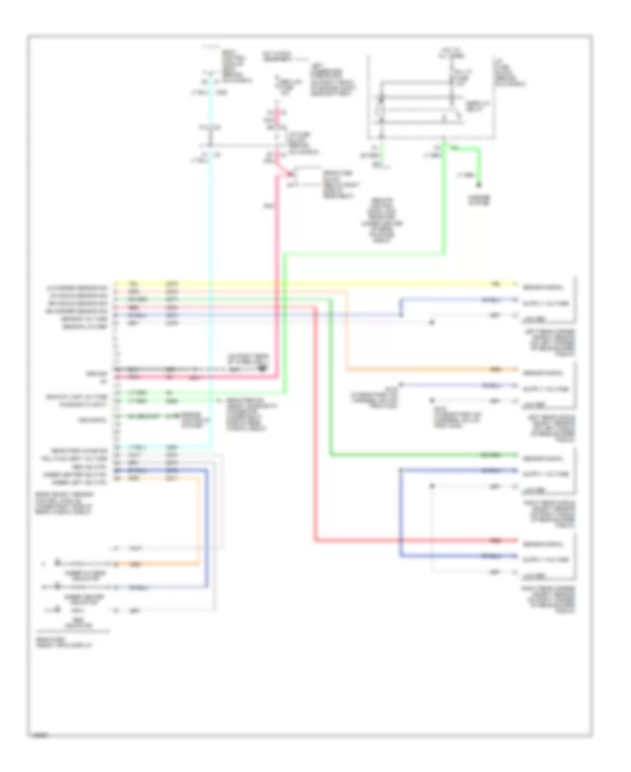
ANTI-LOCK BRAKES
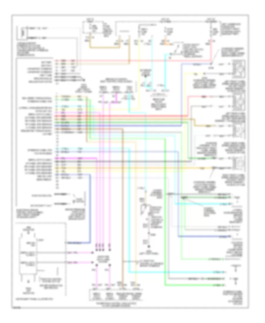
Anti-lock Brakes Wiring Diagram for Buick Park Avenue 2005
List of elements for Anti-lock Brakes Wiring Diagram for Buick Park Avenue 2005:
- (behind glove box) body control module (bcm)
- (in body harness, 35 cm from g202)
- (in body harness, 46 cm from g202)
- (in engine harness, 12.5 cm from right front wheel speed sensor harness breakout)
- (in engine harness, 19 cm from right front wheel speed sensor harness breakout) s112
- (in engine harness, 53 cm from left front wheel speed sensor breakout)
- A1 c3
- A11 c2
- Abs 2 fuse 10a
- Abs fuse 10a
- Abs fuse 50a
- Abs ind lamp
- Abs ind sig
- Abs indicator
- B c6
- B1 c1
- B11
- B12
- B12 c2
- B13
- Battery
- Brake pressure modulator valve (bpmv) (left front of engine compt)
- Computer data lines system
- Delivered torque signal
- Driver information center (dic)
- E9 c3
- Electronic brake control module (ebcm) (left front corner of engine compt)
- Exterior lights system
- F12 c3
- G104 (near left front strut tower)
- G202 (left kick panel)
- Ground-module
- Ground-pump motor
- Hot at all times
- Hot in run
- I/p fuse block (behind glove box)
- Ignition 3
- Instrument panel cluster (ipc)
- Lateral accelerometer sensor (w/ vsc) (under rear seat)
- Lateral accelerometer sig
- Left front wheel speed sensor (wss) (on left front brake assembly, on back of hub)
- Left rear wheel speed sensor (wss) (on left rear brake assembly, on back of hub)
- Left underhood fuse block (on right front of engine compt, near battery)
- Lf wheel spd sens-ref
- Lf wheel spd sens-sig
- Logic
- Low ref
- Lr wheel spd sens-ref
- Lr wheel spd sens-sig
- Nca
- Powertrain control module (pcm) (in air cleaner housing)
- Pump motor
- Pump motor ctrl
- Rear fuse block (below right side of rear seat)
- Red
- Requested torque signal
- Rf wheel spd sens-ref
- Rf wheel spd sens-sig
- Right front wheel speed sensor (wss) (on right front brake assembly, on back of hub)
- Right rear wheel speed sensor (wss) (on right rear brake assembly, on back of hub)
- Rr wheel spd sens-ref
- Rr wheel spd sens-sig
- S111
- S198 (in engine harness, 46.5 cm from left front wheel speed sensor breakout)
- S199
- S220
- S221
- S299
- Sens feed-5v
- Serial data class 2
- Steering wheel pos
- Steering wheel position sensor (w/ vsc) (on base of steering column)
- Stop fuse 20a
- Stoplamp/a/t shift lock control switch (behind dash, on brake pedal support)
- Stoplight sw
- Sw sys batt volt
- Tan
- Trac ctrl sw sig
- Trac off indicator
- Traction control switch (w/ traction control & variable effort steering)
- Traction control system active
- Var effort steering
- Variable effort steering actuator (w/ traction control & variable effort steering) (on power steering rack)
- Vent tube
- W/ traction control & variable effort steering
- Yaw rate sens
- Yaw rate sensor (w/ vsc) (under rear shelf, behind lid hinge)
ANTI-THEFT
Forced Entry Wiring Diagram for Buick Park Avenue 2005
List of elements for Forced Entry Wiring Diagram for Buick Park Avenue 2005:
- A12
- A15
- A16
- Ajar
- Ajar switch
- B (+)
- B15
- B16
- Body control module (bcm) (behind glove box)
- C10
- Class 2 data line
- Computer data lines system
- Cstr/sbm fuse 10a
- D12
- Dome
- Door dome switch
- Driver door lock actuator (rear of right front door)
- Driver door module (inside driver's door, above radio speaker)
- F10
- F11
- Front passenger door lock actuator (rear of right front door)
- G201 (right kick panel)
- G202 (left kick panel)
- G400 (on right rear of wheelwell)
- Gnd
- Headlamp alarm sig
- Headlights system
- Horn relay control
- Horns system
- Hot at all times
- Hot in run or acc
- Hot in run or start
- I/p fuse block (behind glove box)
- Ign
- Instrument panel cluster (ipc)
- Key sw sig
- Key switch
- Left rear door lock actuator (in left rear door)
- Left underhood fuse block (on right front of engine compt, near battery)
- Lf door ajar in
- Lf door open in
- Low reference
- Lr door ajar in
- Lr door open in
- Mem/rfa fuse 10a
- Passenger door module (in front passenger's door)
- Pnk
- Pnk e5
- Pnk f5
- Power distribution system
- Pwr door serial data
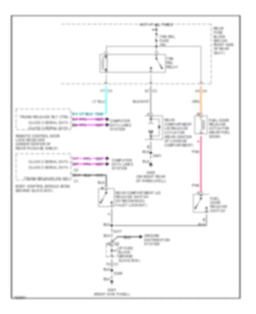
- Rear compartment lid ajar switch (on center of rear compt, on latch)
- Rear door module (rdm) (under right side of rear seat)
- Rear fuse block (below right side of rear seat)
- Red
- Remote control door lock receiver (under center of rear package shelf)
- Rf door ajar in
- Rf door open in
- Right rear door lock actuator (in right rear door)
- Rr door ajar in
- Rr door open in
- S205
- S208
- S401
- Sbm/lcm fuse 10a
- Security ind
- Security indicator
- Serial data
- Serial data class 2
- Tan
- Trunk ajar
- Wsw/rfa fuse 10a
Pass-Key Wiring Diagram for Buick Park Avenue 2005
List of elements for Pass-Key Wiring Diagram for Buick Park Avenue 2005:
- B (+)
- B11
- B12
- Body control module (bcm) (behind glove box)
- D12
- Data link connector (under left side of dash)
- Driver door module (ddm) (inside driver's door, above radio speaker)
- Electronic brake control module (ebcm) (left front corner of engine compartment)
- G202 (left kick panel)
- Ground
- Hot at all times
- Hot in unlock, run or start
- I/p fuse block (behind glove box)
- Ign
- Ignition key
- Instrument panel cluster (ipc)
- Instrument panel integration module (ipm) (behind right side of dash, near rear of glove box)
- Left underhood fuse block (on right front of engine compt, near battery)
- Nca
- Pcm fuse 10a
- Pcm/ cru fuse 10a
- Pnk
- Power distribution system
- Powertrain control module (pcm) (in air cleaner housing)
- Reader/ exciter
- Rear fuse block (below right side of rear seat)
- S298
- Serial data class 2
- Solid state
- Theft deterrent control module (in steering column)
- Transponder
BODY CONTROL MODULES
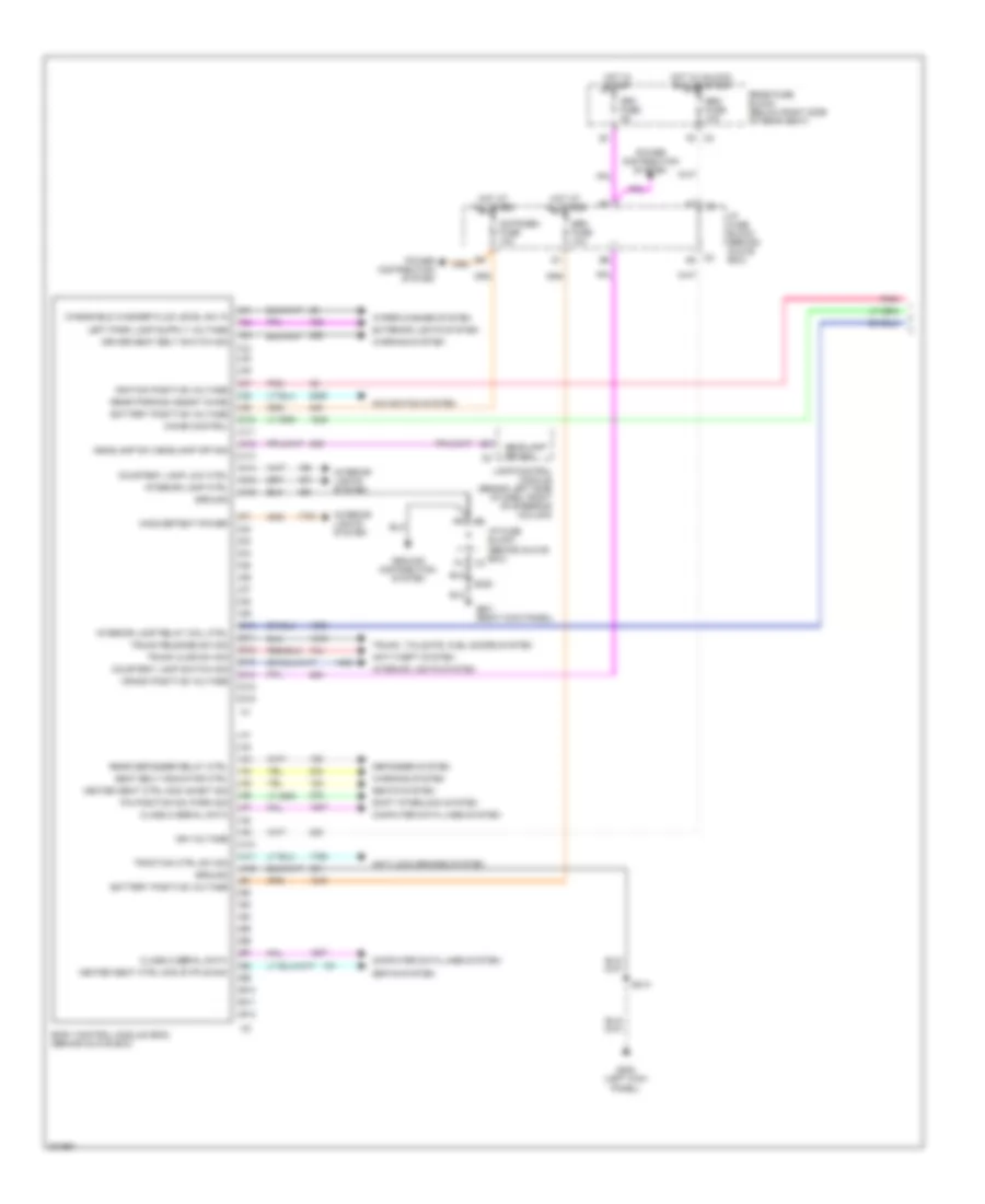
Body Control Modules Wiring Diagram (1 of 2) for Buick Park Avenue 2005
List of elements for Body Control Modules Wiring Diagram (1 of 2) for Buick Park Avenue 2005:
- A10
- A11
- A12
- Anti-lock brakes system
- Anti-theft system
- B10
- B11
- B12
- Battery positive voltage
- Body control module (bcm) (behind glove box)
- C10
- C11
- C12
- C13
- C14
- C15
- C16
- C2 a6
- Chime control
- Class 2 serial data
- Computer data lines system
- Courtesy lamp low ctrl
- Courtesy lamp switch sig
- Crank positive voltage
- Crk fuse 5a
- Cstr/sbm fuse 10a
- D10
- D11
- D12
- D13
- D14
- D15
- D16
- Defogger system
- Driver seat belt switch sig
- Exterior lights system
- F5 c3
- G201 (right kick panel)
- G202 (left kick panel)
- Ground
- Ground distribution system
- Headlamp off sig
- Headlamp sw headlamp off sig
- Heated seat ctrl mod inhibit sig
- Heated seat ctrl mod status sig
- Hot at all times
- Hot in start
- Hot in unlock, run or start
- I/p fuse block (behind glove box)
- Ign voltage
- Ignition positive voltage
- Inadvertent power
- Interior lamp ctrl
- Interior lamp relay coil ctrl
- Interior lights system
- Lamp control module (behind left side of dash, right of steering column)
- Navigation system
- P/n position sw park sig
- Pnk
- Power distribution system
- Rear defogger relay ctrl
- Rear fuse block (below right side of rear seat)
- Rear parking assist chime
- S208
- S213
- Sbm fuse 10a
- Seat belt indicator ctrl
- Seats system
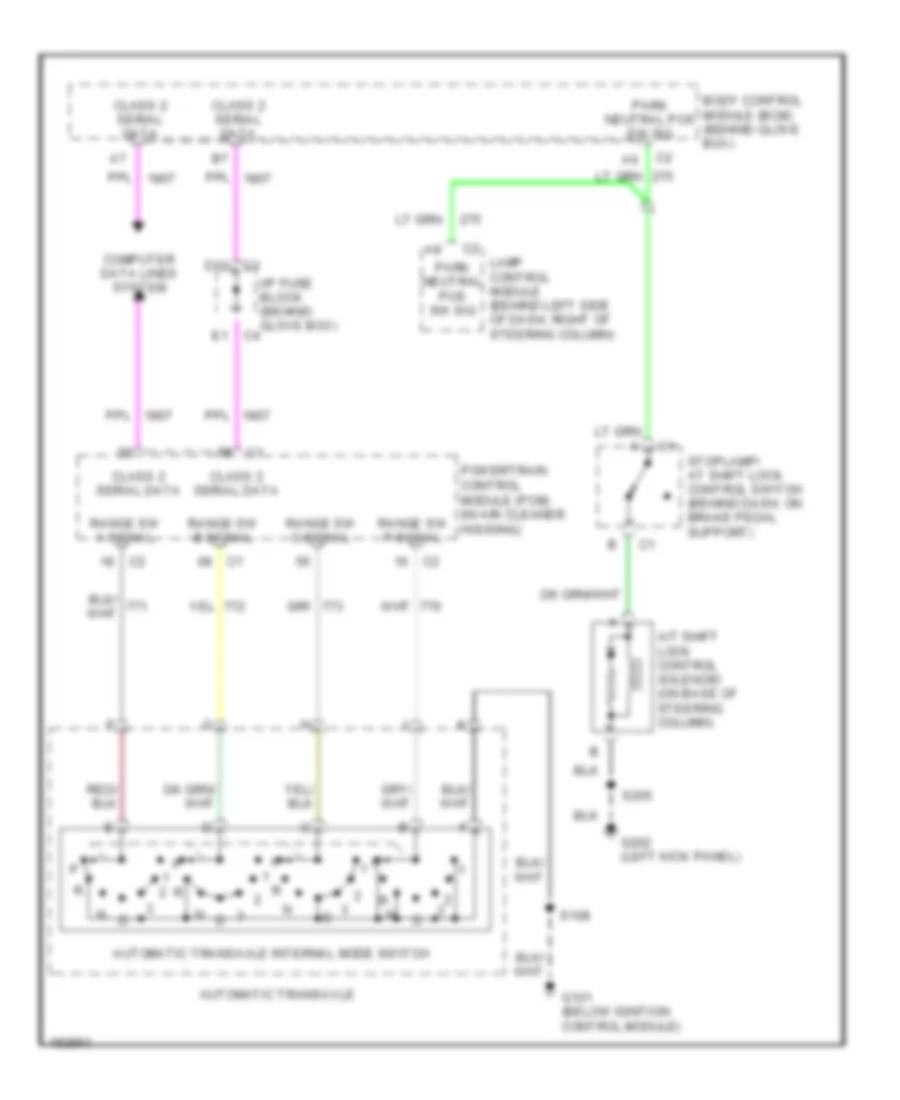
- Shift interlock system
- Traction ctrl sw sig
- Trunk ajar sw sig
- Trunk release sw sig
- Trunk, tailgate, fuel doors system
- Warning system
- Windshield washer fluid level sw in
- Wiper/washer system
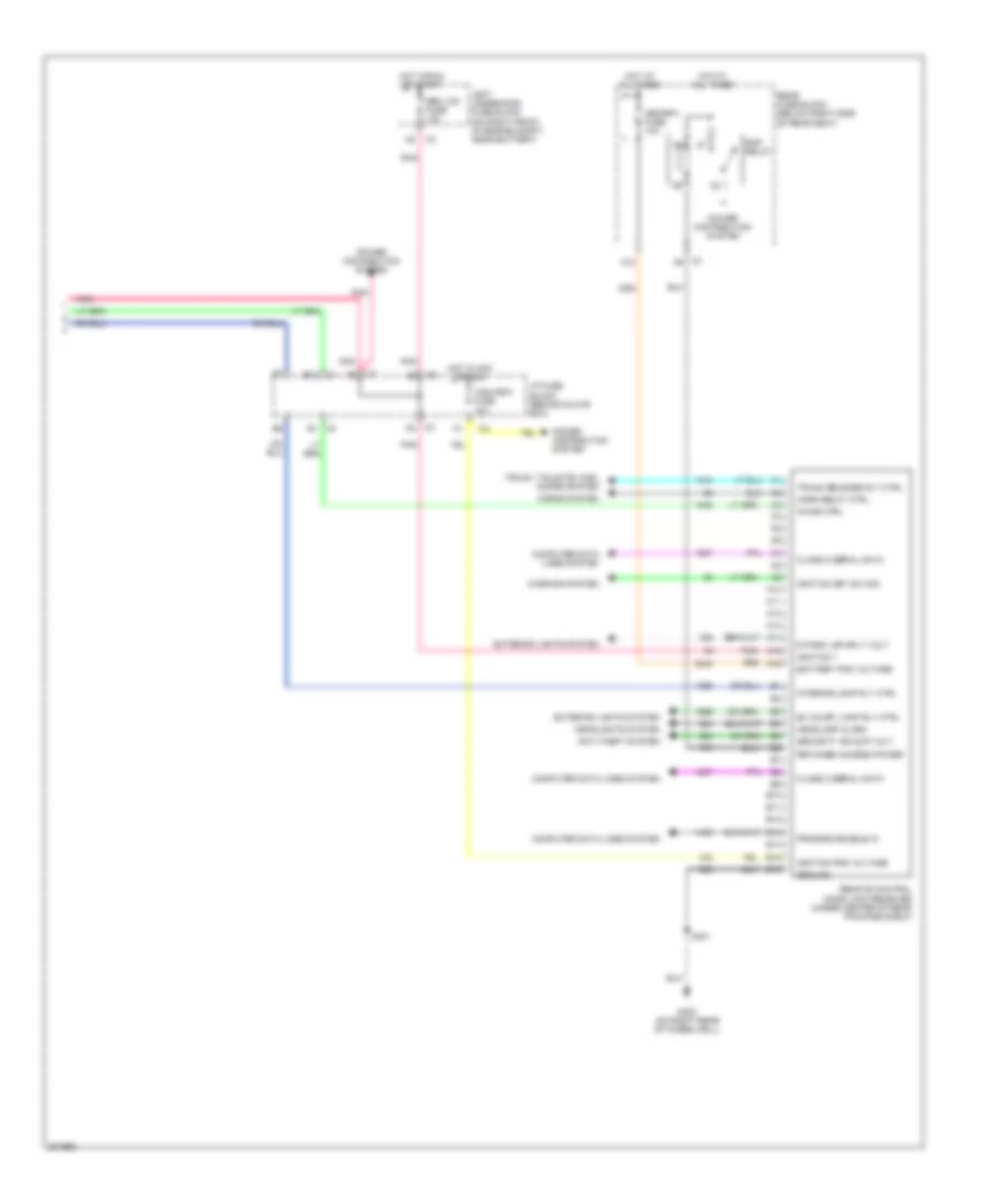
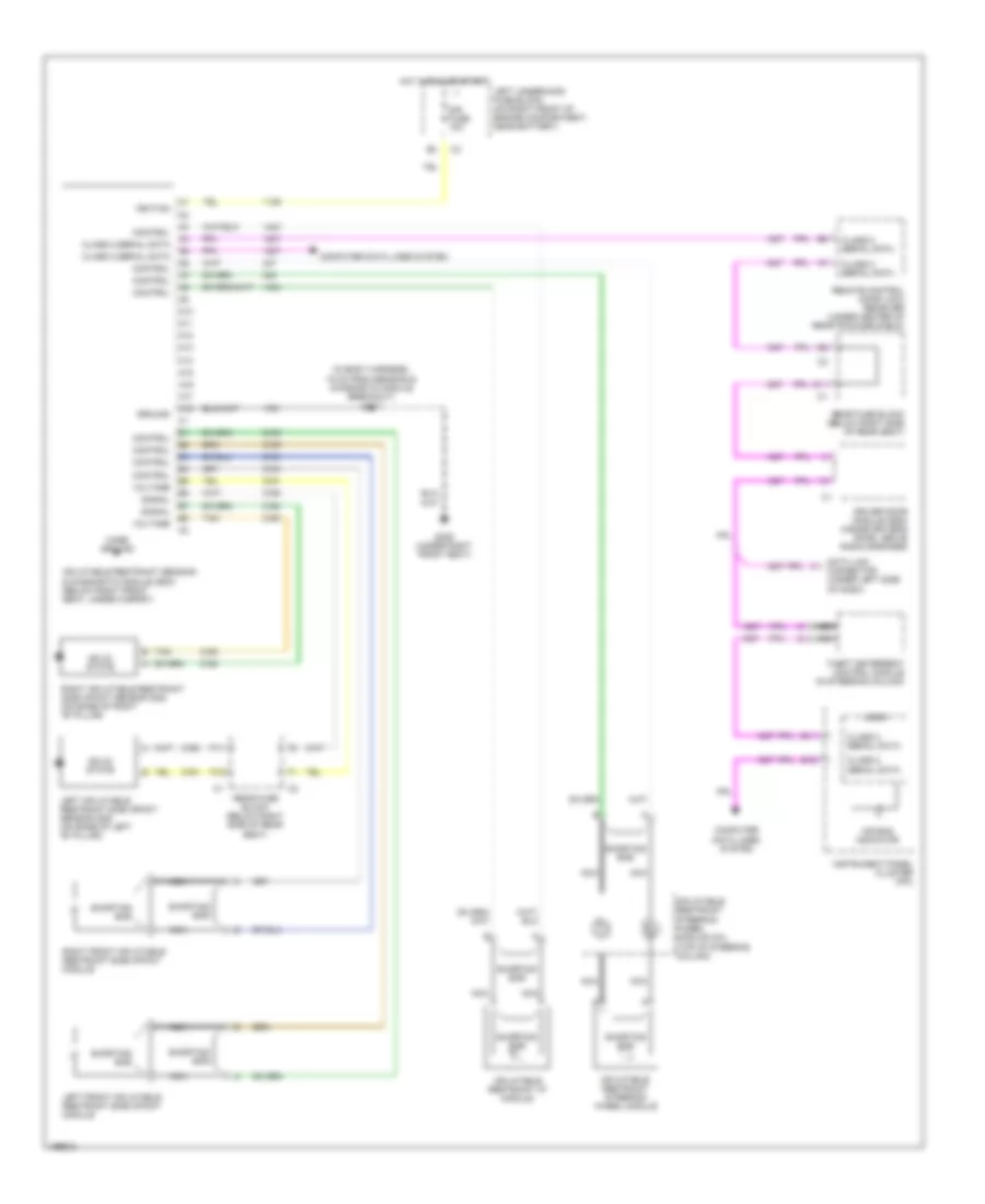
Body Control Modules Wiring Diagram (2 of 2) for Buick Park Avenue 2005
List of elements for Body Control Modules Wiring Diagram (2 of 2) for Buick Park Avenue 2005:
- A10
- A11
- A12
- A13
- A14
- A15
- A16
- Anti-theft system
- B10
- B11
- B12
- B13
- B14
- B15
- B16
- Battery pos voltage
- C3 a5
- C4 b1
- Chime ctrl
- Class 2 serial data
- Computer data lines system
- Ex court lamp rly ctrl
- Exterior lights system
- G400 (on right rear of wheelwell)
- Ground
- Headlamp alarm
- Headlights system
- Horn relay ctrl
- Horns system
- Hot at all times
- Hot in acc or run
- Hot in run or start
- I/p fuse block (behind glove box)
- Ignition 1
- Ignition key sw sig
- Ignition pos voltage
- Interior lamp rly ctrl
- Left underhood fuse block (on right front of engine compt, near battery)
- Mem/rfa fuse 10a
- Pnk
- Power distribution system
- Program enable in
- R park lmp sply volt
- Rap relay
- Rear fuse block (below right side of rear seat)
- Remote control door lock receiver (under center of rear package shelf)
- Retained access power
- S401
- Sbm lcm fuse 10a
- Security ind sup volt
- Trunk release rly ctrl
- Trunk, tailgate, fuel doors system
- Warning system
- Wsw/rfa fuse 10a
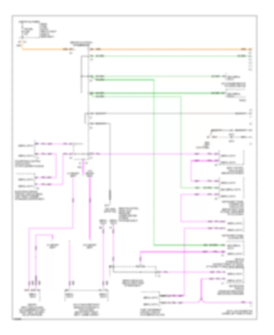
COMPUTER DATA LINES
Computer Data Lines Wiring Diagram for Buick Park Avenue 2005
List of elements for Computer Data Lines Wiring Diagram for Buick Park Avenue 2005:
- (behind glove box) i/p fuse block
- B11
- B12
- B13
- Body control module (bcm) (behind glove box)
- C1 d15
- Cd changer remote playback device
- D11
- D12
- D14
- Data link connector (under left side of dash)
- Driver door module (inside driver's door, above radio speaker)
- E&c serial data
- Electronic brake control module (ebcm) (left front corner of engine compartment)
- G202 (left kick panel)
- Hot at all times
- Inflatable restraint sensing & diagnostic module (sdm) (below right front seat, under carpet)
- Instrument panel cluster (ipc)
- Instrument panel integration module (ipm) (behind right side of dash, near rear of glove box)
- Keyless entry sig
- Memory seat module (msm) (on underside of left front seat, on seat adjuster frame)
- Nca
- Powertrain control module (pcm) (in air cleaner housing)
- Radio
- Rear fuse block (below right side of rear seat)
- Remote control door lock receiver (under center of rear package shelf)
- S210
- S213
- Serial data
- Theft deterrent control module (in steering column)
- Trk rel fuse 15a
- Vehicle interface unit (on right front of trunk, attached to seat back brace)
- W/ memory seat
- W/o memory seat
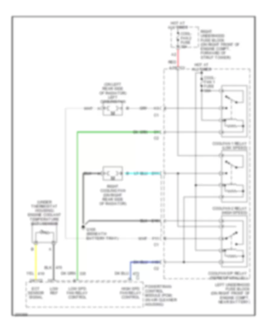
COOLING FAN
Cooling Fan Wiring Diagram for Buick Park Avenue 2005
List of elements for Cooling Fan Wiring Diagram for Buick Park Avenue 2005:
- (on left rear side of radiator) left cooling fan
- (under thermostat housing) engine coolant temperature (ect) sensor
- A10
- Cool- fan 1 fuse 30a
- Cool- fan 2 fuse 30a
- Coolfan 1 relay (low speed)
- Coolfan 2 relay (high speed)
- Coolfan s/p relay (series/parallel)
- D11
- E10
- Ect sensor signal
- F11
- G105 (beneath battery tray)
- High spd fan relay control
- Hot at all times
- Left underhood fuse block (on right front of engine compt, near battery)
- Low ref
- Low spd fan relay control
- Powertrain control module (pcm) (in air cleaner housing)
- Red
- Right cooling fan (on right rear side of radiator)
- Right underhood fuse block (on right front of engine compt, forward of strut tower)
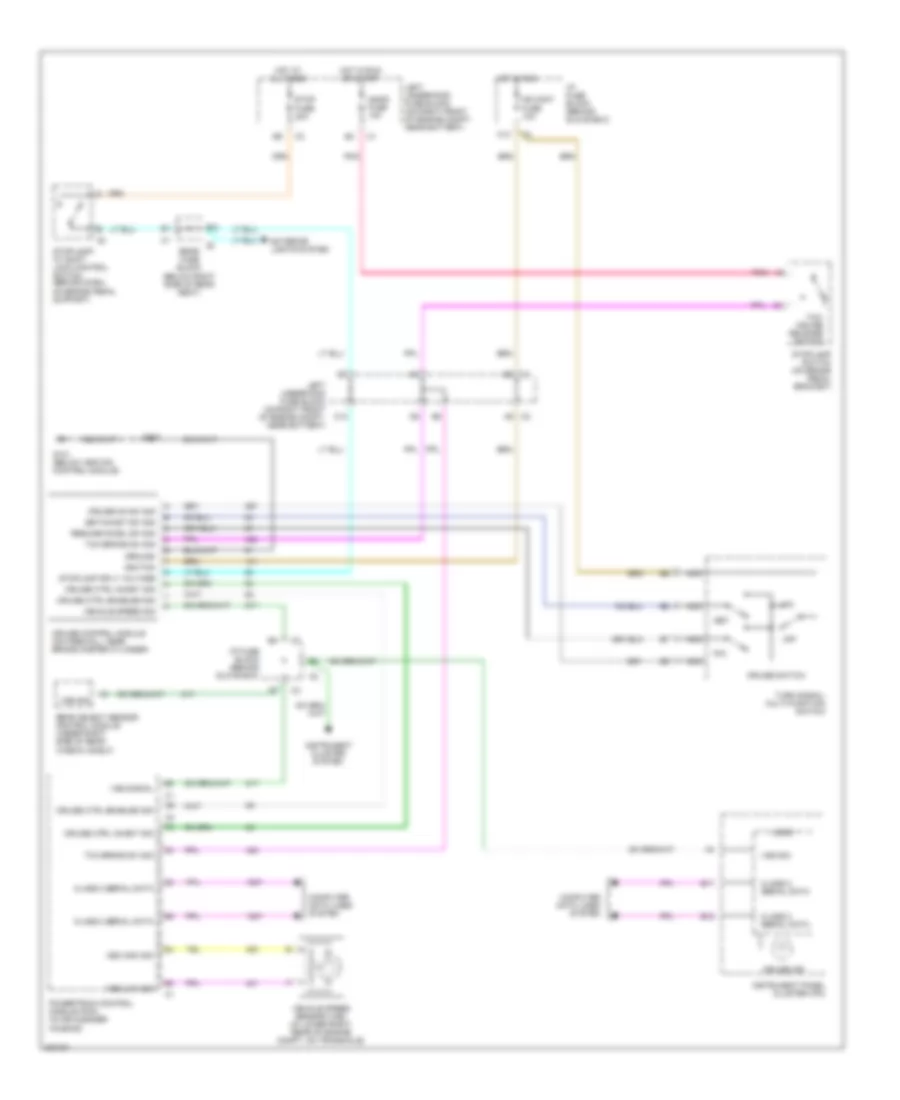
CRUISE CONTROL
Cruise Control Wiring Diagram for Buick Park Avenue 2005
List of elements for Cruise Control Wiring Diagram for Buick Park Avenue 2005:
- A6 c2
- All times
- B11
- B12
- B6 c3
- C10
- C12
- Class 2 serial data
- Computer data lines system
- Cr cont fuse 10a
- Cruise control module (on firewall, near brake master cylinder)
- Cruise ctrl enabled sig
- Cruise ctrl inhibit sig
- Cruise ind
- Cruise on sw sig
- Cruise switch
- Exterior lights system
- G101 (below ignition control module)
- Ground
- Hot at
- Hot in run
- Hot in run or start
- I/p fuse block (behind glove box)
- Ignfd fuse 10a
- Ignition
- Instrument cluster system
- Instrument panel cluster (ipc)
- Left underhood fuse block (on right front of engine compt, near battery)
- Logic
- Nca
- Off
- Pnk
- Powertrain control module (pcm) (in air cleaner housing)
- R/a
- Rear fuse block (below right side of rear seat)
- Rear object sensor control module (under right side of rear window shelf)
- Resume/accel sw sig
- S108
- Set
- Set/coast sw sig
- Stop fuse 20a
- Stoplamp sply voltage
- Stoplamp switch (on brake pedal bracket)
- Stoplamp/ at shift lock control switch (behind dash, on brake pedal support)
- Tcc brake sw sig
- Tcc/ cruise release switch
- Turn signal/ multi-function switch
- Vehicle speed sensor (vss) (in lower right rear of engine compt, on transaxle)
- Vehicle speed sig
- Vss high sig
- Vss low sig
- Vss sig
- Vss signal
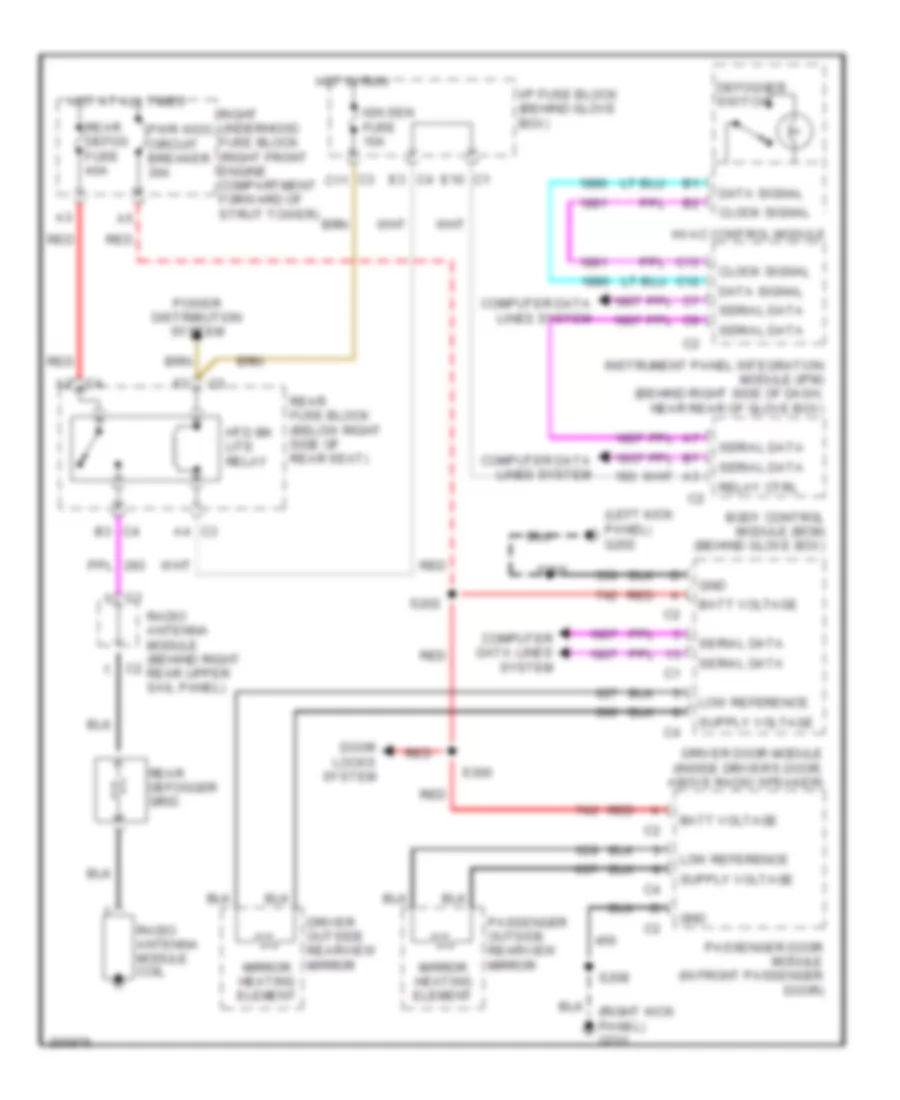
DEFOGGERS
Defoggers Wiring Diagram for Buick Park Avenue 2005
List of elements for Defoggers Wiring Diagram for Buick Park Avenue 2005:
- (left kick panel) g202
- A2 c4
- A4 c3
- B3 c4
- Batt voltage
- Body control module (bcm) (behind glove box)
- C12
- C13
- C3 c11
- Clock signal
- Computer data lines system
- Data signal
- Defogger switch
- Door locks system
- Driver door module (inside driver's door, above radio speaker)
- Driver outside rearview mirror
- E10 c1
- E3 c4
- Gnd
- Hot at all times
- Hot in run
- Htd bk lite relay
- Hvac control module
- I/p fuse block (behind glove box)
- Ign sen fuse 10a
- Instrument panel integration module (ipm) (behind right side of dash, near rear of glove box)
- Low reference
- Mirror heating element
- Passenger door module (in front passenger door)
- Passenger outside rearview mirror
- Power distribution system
- Pwr wdo circuit breaker 30a
- Radio antenna module (behind right rear upper sail panel)
- Radio antenna module coil
- Rear defog fuse 40a
- Rear defogger grid
- Rear fuse block (below right side of rear seat)
- Red
- Relay ctrl
- Right underhood fuse block (right front engine compartment forward of strut tower)
- S202
- S205
- S208
- S300
- Serial data
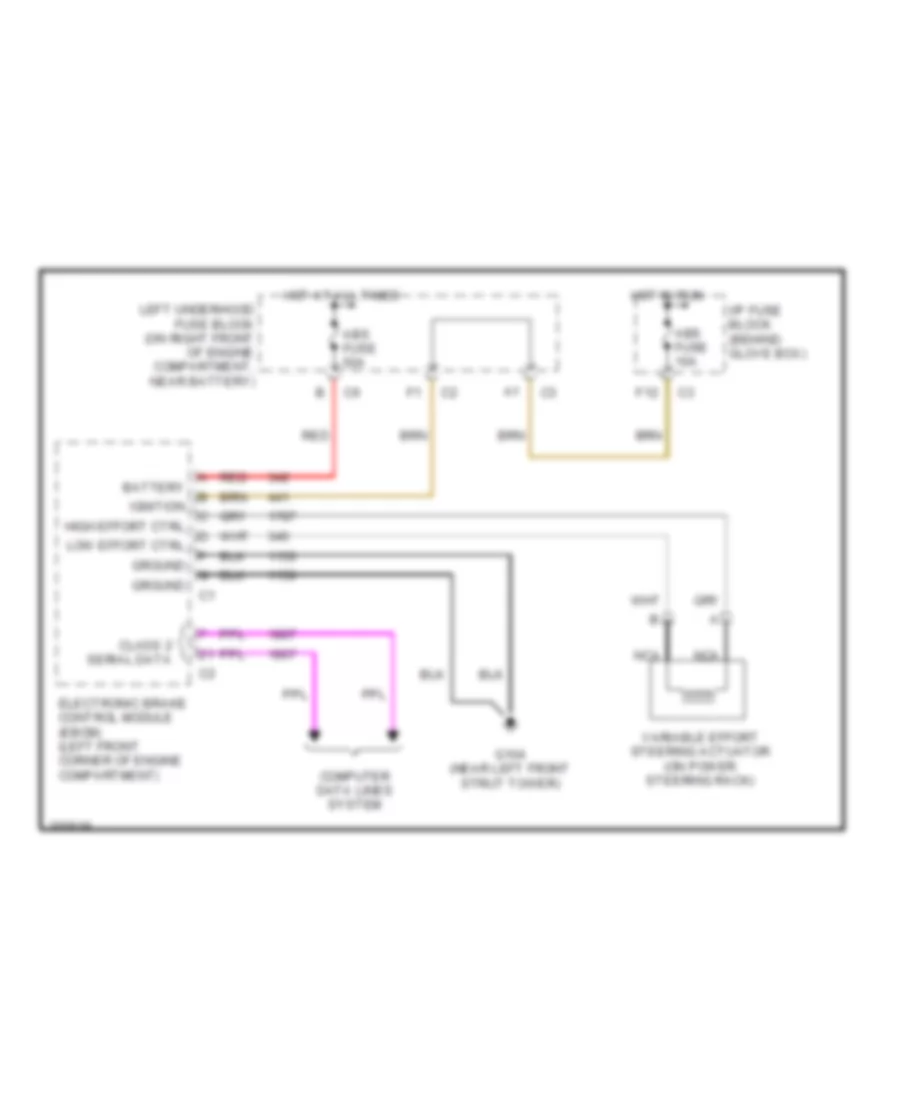
ELECTRONIC POWER STEERING
Electronic Power Steering Wiring Diagram for Buick Park Avenue 2005
List of elements for Electronic Power Steering Wiring Diagram for Buick Park Avenue 2005:
- Abs fuse 10a
- Abs fuse 50a
- Battery
- Class 2 serial data
- Computer data lines system
- Electronic brake control module (ebcm) (left front corner of engine compartment)
- F12
- G104 (near left front strut tower)
- Ground
- High effort ctrl
- Hot at all times
- Hot in run
- I/p fuse block (behind glove box)
- Ignition
- Left underhood fuse block (on right front of engine compartment, near battery)
- Low effort ctrl
- Nca
- Red
- Variable effort steering actuator (on power steering rack)
ELECTRONIC SUSPENSION
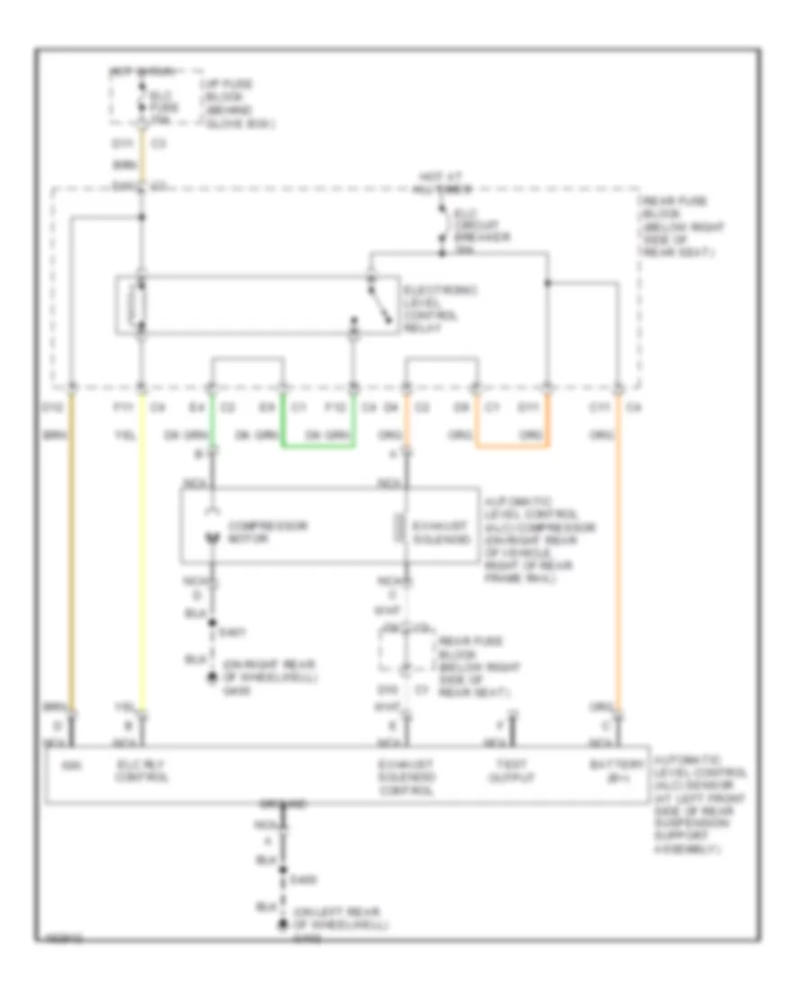
Electronic Suspension Wiring Diagram for Buick Park Avenue 2005
List of elements for Electronic Suspension Wiring Diagram for Buick Park Avenue 2005:
- (on left rear of wheelwell) g402
- (on right rear of wheelwell) g400
- Automatic level control (alc) compressor (on right rear of vehicle, right of rear frame rail)
- Automatic level control (alc) sensor (at left front side of rear suspension support assembly)
- Battery (b+)
- C11
- Compressor motor
- D10
- D11
- D12
- Elc circuit breaker 30a
- Elc fuse 10a
- Elc rly control
- Electronic level control relay
- Exhaust solenoid
- Exhaust solenoid control
- F11
- F12
- Ground
- Hot at all times
- Hot in run
- I/p fuse block (behind glove box)
- Ign
- Nca
- Nca c
- Rear fuse block (below right side of rear seat)
- S400
- S401
- Test output
ENGINE PERFORMANCE
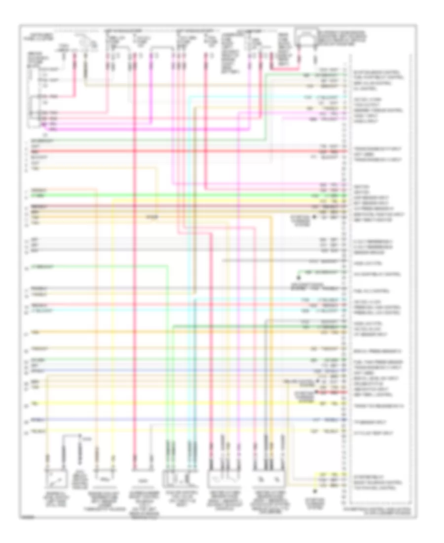
3.8L VIN 1
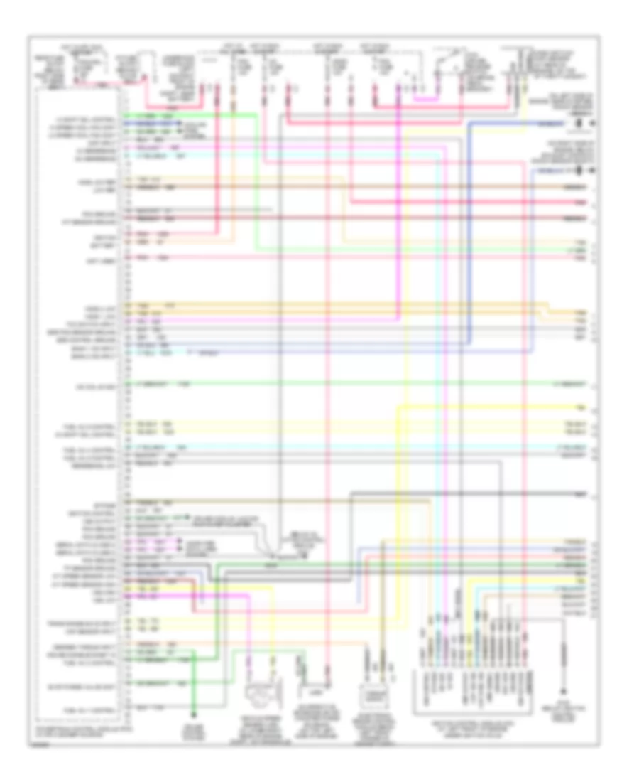
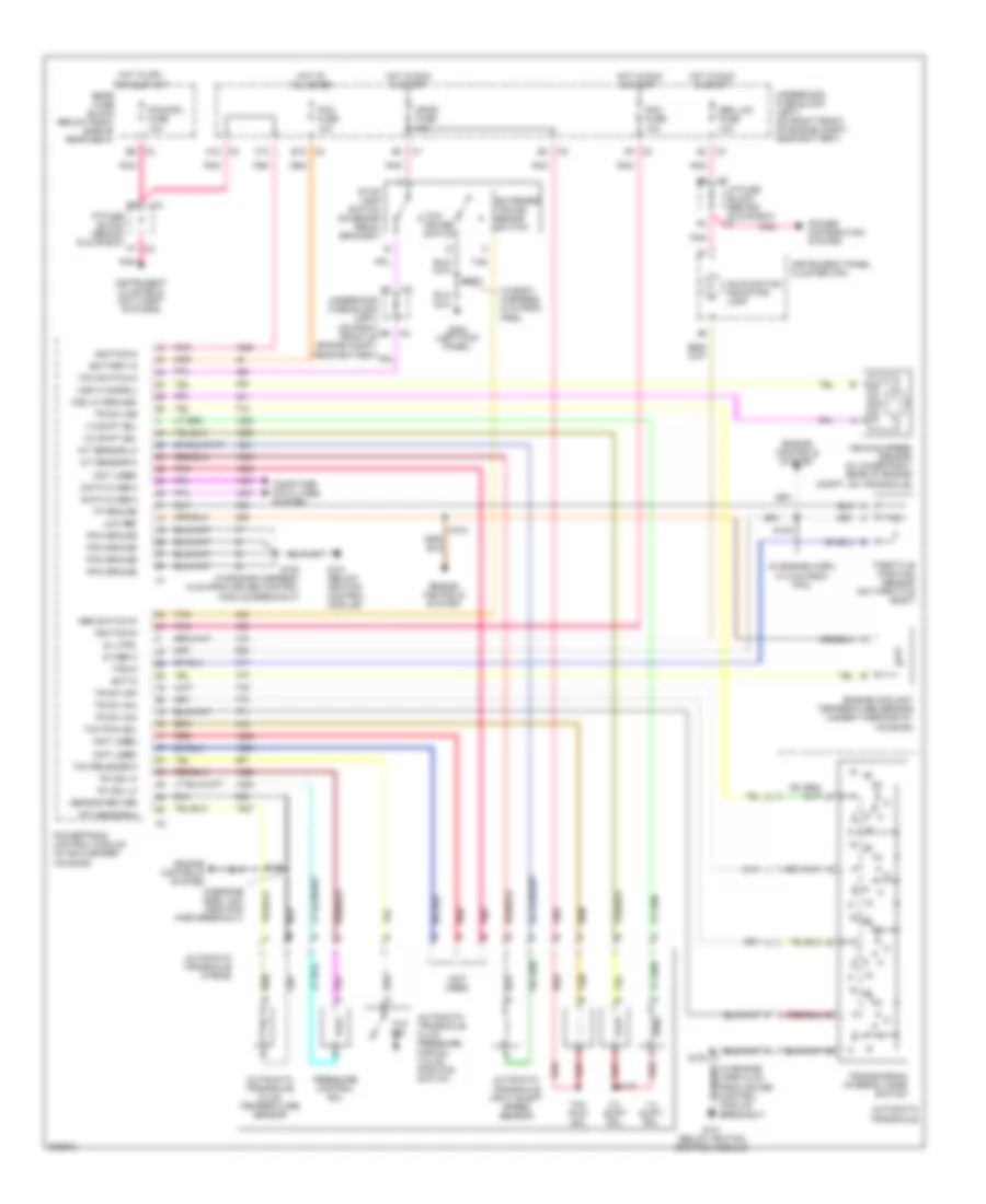
3.8L VIN 1, Engine Performance Wiring Diagram (1 of 4) for Buick Park Avenue 2005
List of elements for 3.8L VIN 1, Engine Performance Wiring Diagram (1 of 4) for Buick Park Avenue 2005:
- (below ig- nition control module) g101
- (not used)
- (on left side of engine, near starter) knock sensor (bank 1)
- (on right side of engine, below exhaust manifold) knock sensor (bank 2)
- 1-2 shift sol control
- 18x ref
- 18x reference
- 2-3 shift sol control
- 3x ref
- 3x reference
- A/t speed sensor high
- A/t speed sensor low
- A12
- Bank 1 ks input
- Bank 2 ks input
- Battery
- Box)
- Bypass
- C3i fuse 10a
- Ckp 18x sig
- Ckp sync sig
- Cmp input
- Cmp output
- Cmp signal
- Computer data lines system
- Cooling fans system
- Cruise control system
- Cruise disable/inhibit in
- Cruise module, hud dis- play & inst cluster
- Desired torque input
- E12
- Egr control ground
- Egr pos sensor ground
- Electronic brake control module (ebcm) (left front corner of engine compt)
- Evap purge valve cont
- Evaporative emissions (evap) canister purge solenoid (on top left side of engine)
- F12
- Fuel inj 1 control
- Fuel inj 2 control
- Fuel inj 4 control
- Fuel inj 5 control
- Fuel inj 6 control
- G100 (below ignition control module)
- Ground
- Hi speed cool fan cont
- Ho2s 1 low
- Ho2s 2 low
- Ho2s low ref
- Hot at all times
- Hot in off, run & start
- Hot in run & start
- I/p fuse block (behind glove f6
- Iac coil b high
- Iat sensor ground
- Ign
- Ign control
- Ign voltage
- Ignfd fuse 10a
- Ignition
- Ignition control
- Ignition control module (icm) (at left front of engine, under ignition coils)
- Lo speed cool fan cont
- Low ref
- Maf sensor input
- Mass air flow (maf) sensor (at rear of engine, on top of throttle body)
- Pcm fuse 10a
- Pcm ground
- Pcm/cru fuse 10a c3
- Pnk
- Pnk a
- Pnk p
- Powertrain control module (pcm) (in air cleaner housing)
- Rear fuse block (below right side of rear seat)
- Ref low
- Reference low
- S108
- Serial data (class 2)
- Signal
- Tan
- Tcc switch input
- Tcc/ cruise release switch (on brake pedal bracket)
- Torque signal
- Tp sensor ground
- Trans range sw b input
- Underhood fuse block (left) (on right front of engine compt, near battery)
- Vehicle speed sensor (vss) (in lower right rear of engine compt, on transaxle)
- Vss high
- Vss low
- Vss output
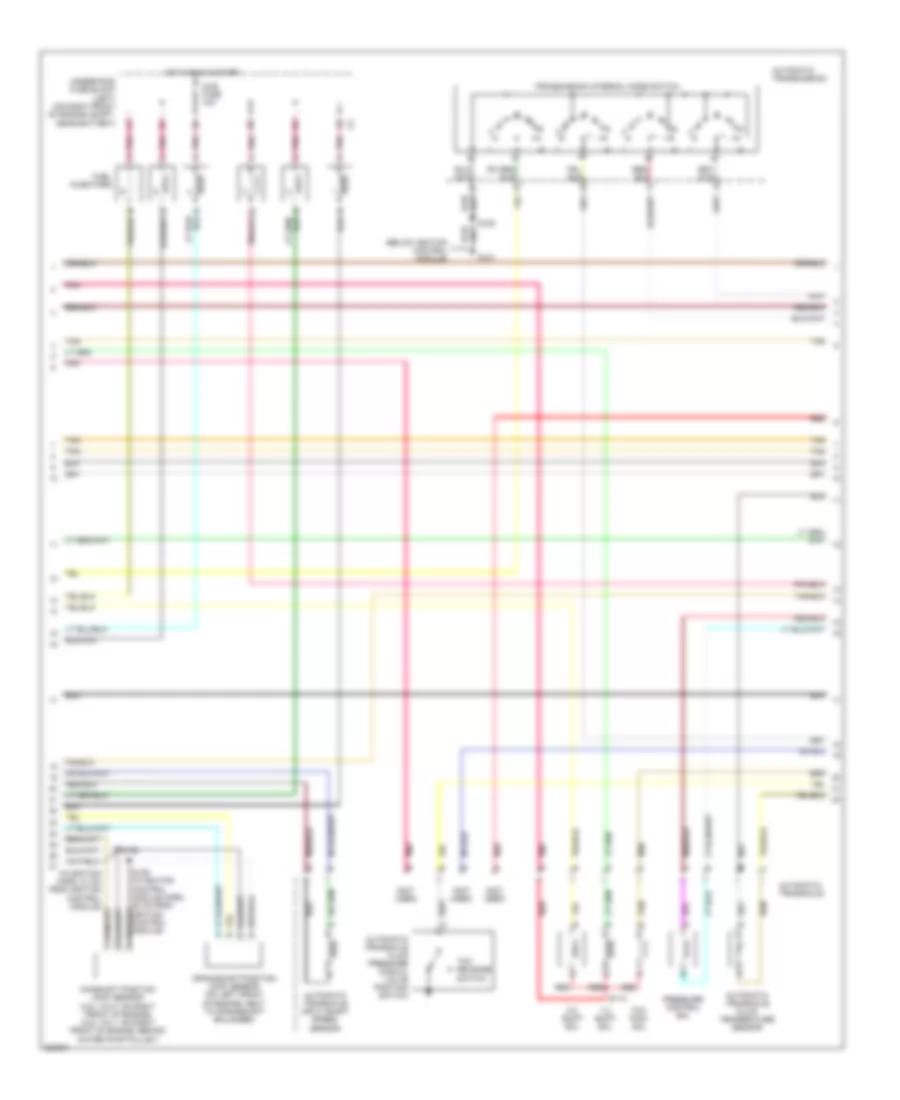
3.8L VIN 1, Engine Performance Wiring Diagram (2 of 4) for Buick Park Avenue 2005
List of elements for 3.8L VIN 1, Engine Performance Wiring Diagram (2 of 4) for Buick Park Avenue 2005:
- (below ignition control module)
- (in ignition harn, 21 cm from ignition control module)
- (not used)
- 1-2 shift sol
- 2-3 shift sol
- Automatic transaxle
- Automatic transaxle fluid pressure manual valve position switch
- Automatic transaxle fluid temperature sensor
- Automatic transaxle input shaft speed sensor
- Automatic transmission
- Camshaft position (cmp) sensor (3.8l vin k: on right front of engine) (3.8l vin 1: on right front of engine, behind water pump pulley)
- Crankshaft position (ckp) sensor (on left front of engine, next to crankshaft balancer)
- Fuel injectors
- G101
- Hot in run & start
- Injr fuse 10a
- Pnk
- Pressure control sol
- Red
- S108
- S113
- S135
- S136 (in ignition control module harn, 20 cm from ignition control module)
- Tan
- Tcc pwm sol
- Tcc release switch
- Transmission internal mode switch
- Underhood fuse block (left) (on right front of engine compt, near battery)
3.8L VIN 1, Engine Performance Wiring Diagram (3 of 4) for Buick Park Avenue 2005
List of elements for 3.8L VIN 1, Engine Performance Wiring Diagram (3 of 4) for Buick Park Avenue 2005:
- (below ignition control module) g101
- (in engine harn, 4 cm from pcm harn breakout)
- (in engine harness, 47.5 cm from pcm) s105
- (in fuel tank) fuel pump & sender assembly
- (left kick panel)
- (on right rear of wheelwell) g400
- A/c refrigerant pressure sensor (near a/c compressor, on hose assembly)
- Engine compartment,
- Engine oil pressure sensor (below power steering pump)
- Exhaust gas recirculation (egr) valve (on top right rear of engine)
- F/pmp fuse 20a
- Fuel pump
- Fuel pump relay
- Fuel tank pressure sensor (in fuel tank)
- G202
- Hot at all times
- Intake air temperature (iat) sensor (in air intake assembly)
- Manifold absolute pressure (map) sensor (on top right side of engine)
- Near battery)
- Red
- S104
- S108
- S115
- S203
- S401
- Stop lamp switch (on brake pedal bracket)
- Tan
- Throttle position (tp) sensor (on throttle body)
- Underhood fuse block (left) (on right front of
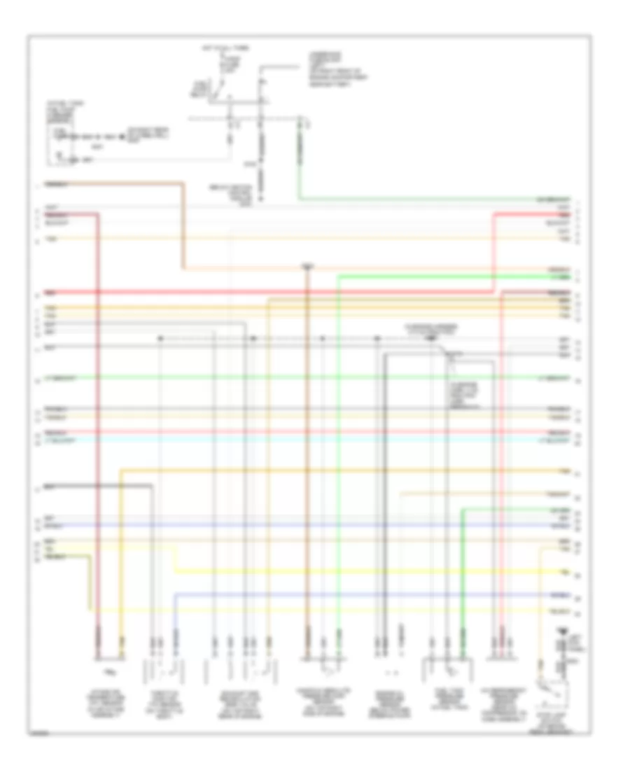
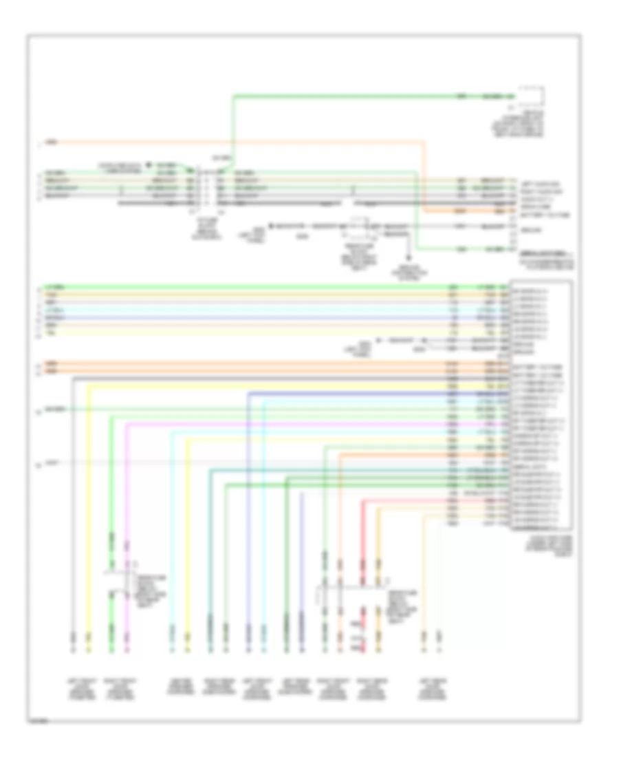
3.8L VIN 1, Engine Performance Wiring Diagram (4 of 4) for Buick Park Avenue 2005
List of elements for 3.8L VIN 1, Engine Performance Wiring Diagram (4 of 4) for Buick Park Avenue 2005:
- (behind glove box) i/p fuse block
- (not used)
- 5 volt reference a
- 5 volt reference b
- A/c clu fuse 10a
- A/c comp relay control
- A/c press sensor in
- A/t fluid temp input
- A13
- Abs switch input
- Air conditioning system
- Boost solenoid control
- C11
- Crk fuse 5a
- Cruise control system
- Cruise status
- D11
- Desired torque control
- E11
- E12
- Ect sensor input
- Egr pintel position input
- Egr valve control
- Eng oil level sw input
- Eng oil press sensor in
- Engine coolant temperature (ect) sensor (under thermostat housing)
- Engine oil level switch (left side of oil pan)
- Evap solenoid control
- Evaporative emissions canister vent solenoid (below rear of vehicle, on evap canister)
- Fuel inj 3 control
- Fuel pump relay control
- Fuel tank press sensor
- G101 (below ignition control module)
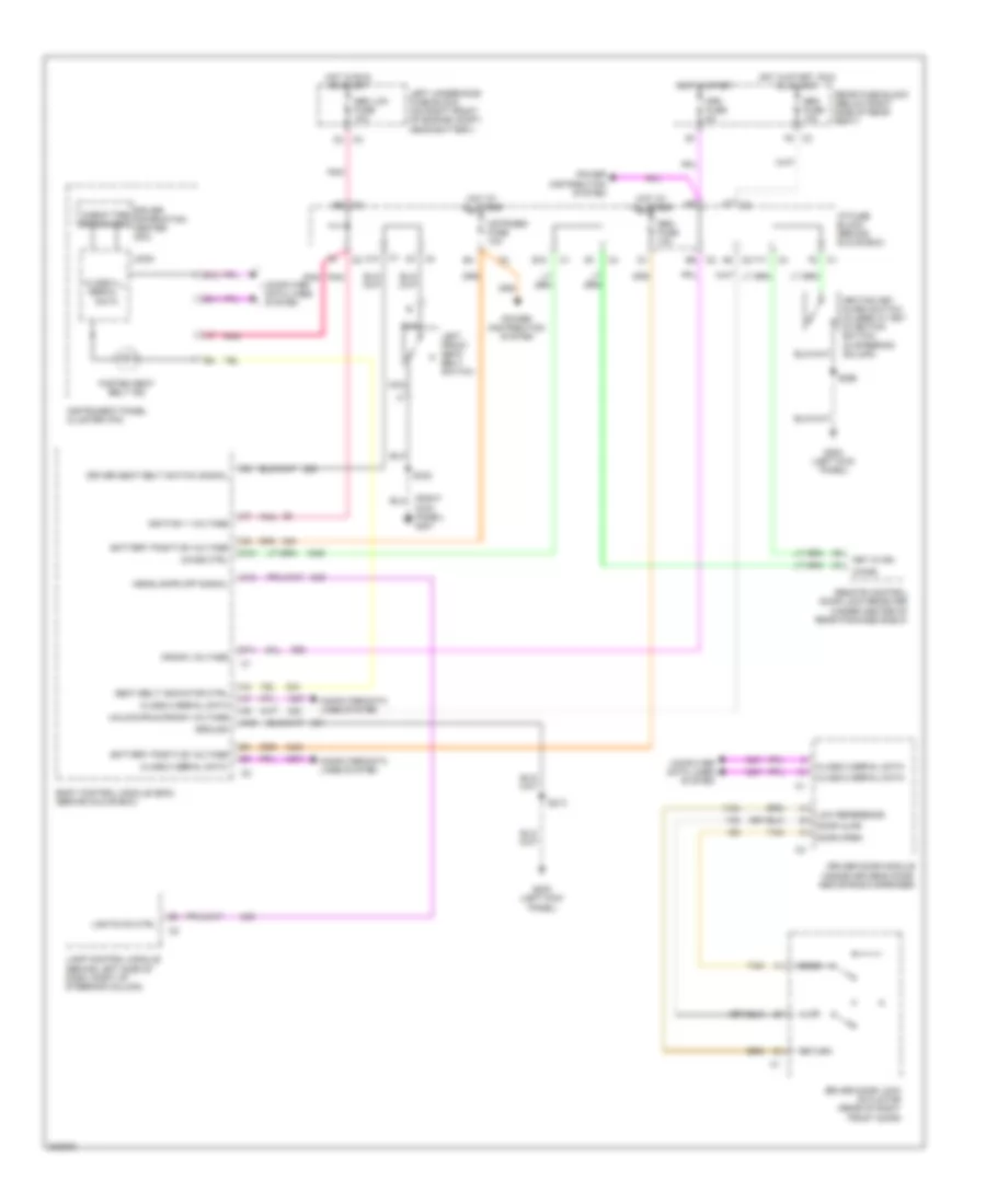
- Gen term f monitor
- Gen term l control
- Heated oxygen sensor (ho2s) (bank 1 sensor 1) (on right exhaust manifold)
- Heated oxygen sensor (ho2s) (bank 1 sensor 2) (on exhaust system, rear of catalytic converter)
- Ho2s 1 input
- Ho2s 2 input
- Ho2s low ctrl
- Hot in run & start
- Hot in start
- Iac coil a high
- Iac coil a low
- Iac coil b low
- Iat sensor input
- Idle air control (iac) valve (on throttle body)
- Ignition
- Instrument panel cluster
- Map sensor input
- Mil control
- Mil ind
- Nca
- Oxy sen fuse 10a
- Pcm fuse 10a
- Pnk
- Powertrain control module (pcm) (in air cleaner housing)
- Press sol high control
- Press sol low control
- Rear fuse block (below right side of rear seat)
- Red
- S103
- S108
- Sbm lcm fuse 10a
- Sensor ground
- Starter relay
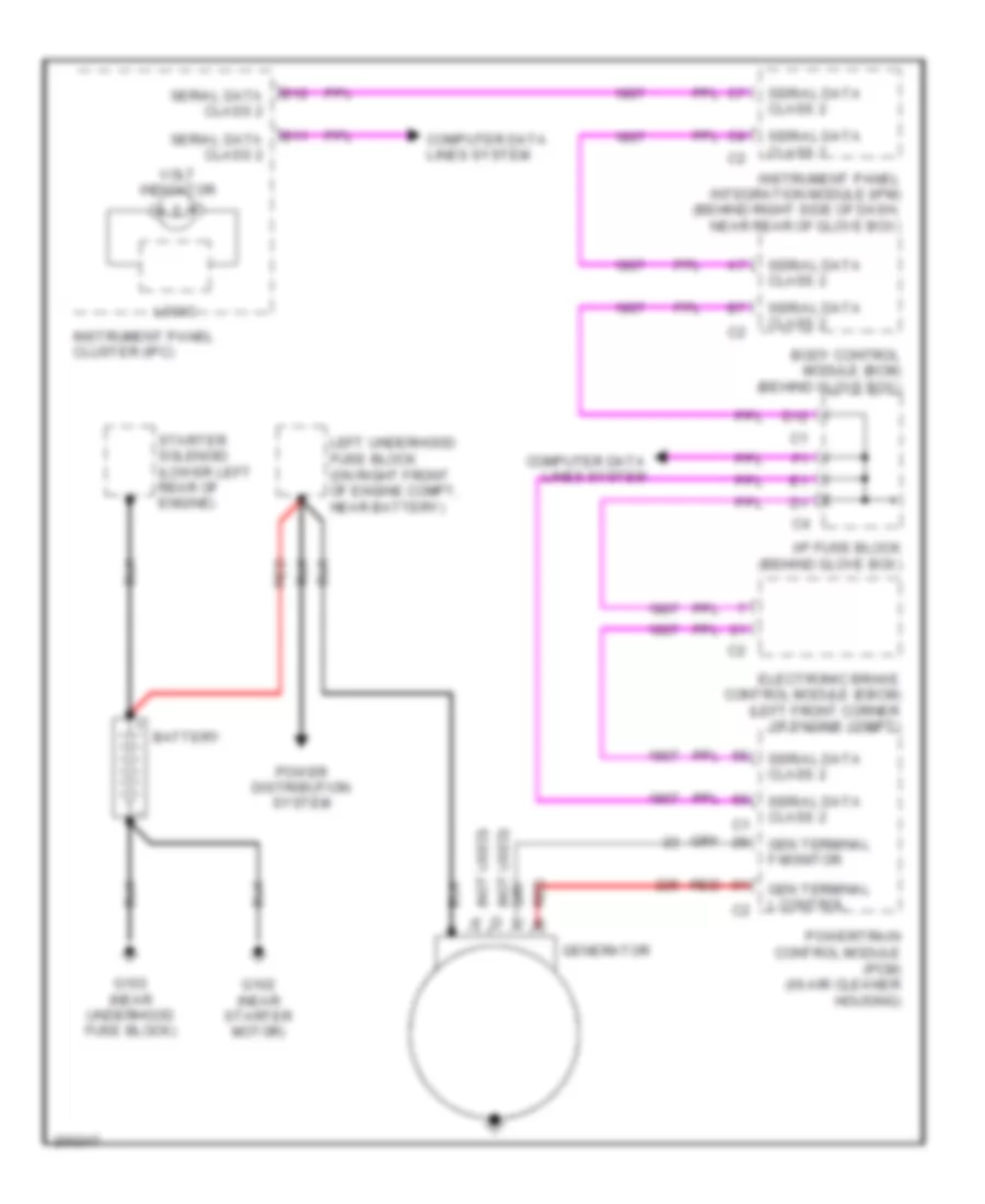
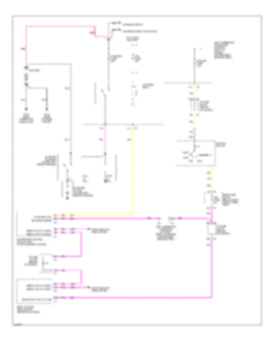
- Starting/ charging system
- Supercharger boost control solenoid (vin 1) (on top left rear of engine, near oil fill)
- Tach input
- Tach output
- Tan
- Tcc pwm sol control
- Tp sensor input
- Trans range sw a input
- Trans range sw c input
- Trans range sw p input
- Trans tcc release sw in
- Underhood fuse block (left) (on right front of engine compt, near battery)
3.8L VIN K
3.8L VIN K, Engine Performance Wiring Diagram (1 of 4) for Buick Park Avenue 2005
List of elements for 3.8L VIN K, Engine Performance Wiring Diagram (1 of 4) for Buick Park Avenue 2005:
- (below ig- nition control module) g101
- (not used)
- (on left side of engine, near starter) knock sensor (bank 1)
- (on right side of engine, below exhaust manifold) knock sensor (bank 2)
- 1-2 shift sol control
- 18x ref
- 18x reference
- 2-3 shift sol control
- 3x ref
- 3x reference
- A/t speed sensor high
- A/t speed sensor low
- A12
- Bank 1 ks input
- Bank 2 ks input
- Battery
- Box)
- Bypass
- C3i fuse 10a
- Ckp 18x sig
- Ckp sync sig
- Cmp input
- Cmp output
- Cmp signal
- Computer data lines system
- Cooling fans system
- Cruise control system
- Cruise disable/inhibit in
- Cruise module, hud dis- play & inst cluster
- Desired torque input
- E12
- Egr control ground
- Egr pos sensor ground
- Electronic brake control module (ebcm) (left front corner of engine compt)
- Evap purge valve cont
- Evaporative emissions (evap) canister purge solenoid (on top left side of engine)
- F12
- Fuel inj 1 control
- Fuel inj 2 control
- Fuel inj 4 control
- Fuel inj 5 control
- Fuel inj 6 control
- G100 (below ignition control module)
- Ground
- Hi speed cool fan cont
- Ho2s 1 low
- Ho2s 2 low
- Ho2s low ref
- Hot at all times
- Hot in off, run & start
- Hot in run & start
- I/p fuse block (behind glove f6
- Iac coil b high
- Iat sensor ground
- Ign
- Ign control
- Ign voltage
- Ignfd fuse 10a
- Ignition
- Ignition control
- Ignition control module (icm) (at left front of engine, under ignition coils)
- Lo speed cool fan cont
- Low ref
- Maf sensor input
- Mass air flow (maf) sensor (at rear of engine, on top of throttle body)
- Pcm fuse 10a
- Pcm ground
- Pcm/cru fuse 10a c3
- Pnk
- Pnk a
- Pnk p
- Powertrain control module (pcm) (in air cleaner housing)
- Rear fuse block (below right side of rear seat)
- Ref low
- Reference low
- S108
- Serial data (class 2)
- Signal
- Tan
- Tcc switch input
- Tcc/ cruise release switch (on brake pedal bracket)
- Torque signal
- Tp sensor ground
- Trans range sw b input
- Underhood fuse block (left) (on right front of engine compt, near battery)
- Vehicle speed sensor (vss) (in lower right rear of engine compt, on transaxle)
- Vss high
- Vss low
- Vss output
3.8L VIN K, Engine Performance Wiring Diagram (2 of 4) for Buick Park Avenue 2005
List of elements for 3.8L VIN K, Engine Performance Wiring Diagram (2 of 4) for Buick Park Avenue 2005:
- (below ignition control module)
- (in ignition harn, 21 cm from ignition control module)
- (not used)
- 1-2 shift sol
- 2-3 shift sol
- Automatic transaxle
- Automatic transaxle fluid pressure manual valve position switch
- Automatic transaxle fluid temperature sensor
- Automatic transaxle input shaft speed sensor
- Automatic transmission
- Camshaft position (cmp) sensor (3.8l vin k: on right front of engine) (3.8l vin 1: on right front of engine, behind water pump pulley)
- Crankshaft position (ckp) sensor (on left front of engine, next to crankshaft balancer)
- Fuel injectors
- G101
- Hot in run & start
- Injr fuse 10a
- Pnk
- Pressure control sol
- Red
- S108
- S113
- S135
- S136 (in ignition control module harn, 20 cm from ignition control module)
- Tan
- Tcc pwm sol
- Tcc release switch
- Transmission internal mode switch
- Underhood fuse block (left) (on right front of engine compt, near battery)
3.8L VIN K, Engine Performance Wiring Diagram (3 of 4) for Buick Park Avenue 2005
List of elements for 3.8L VIN K, Engine Performance Wiring Diagram (3 of 4) for Buick Park Avenue 2005:
- (below ignition control module) g101
- (in engine harn, 4 cm from pcm harn breakout)
- (in engine harness, 47.5 cm from pcm) s105
- (in fuel tank) fuel pump & sender assembly
- (left kick panel)
- (on right rear of wheelwell) g400
- A/c refrigerant pressure sensor (near a/c compressor, on hose assembly)
- Engine compartment,
- Engine oil pressure sensor (below power steering pump)
- Exhaust gas recirculation (egr) valve (on top right rear of engine)
- F/pmp fuse 20a
- Fuel pump
- Fuel pump relay
- Fuel tank pressure sensor (in fuel tank)
- G202
- Hot at all times
- Intake air temperature (iat) sensor (in air intake assembly)
- Manifold absolute pressure (map) sensor (on top right side of engine)
- Near battery)
- Red
- S104
- S108
- S115
- S203
- S401
- Stop lamp switch (on brake pedal bracket)
- Tan
- Throttle position (tp) sensor (on throttle body)
- Underhood fuse block (left) (on right front of
3.8L VIN K, Engine Performance Wiring Diagram (4 of 4) for Buick Park Avenue 2005
List of elements for 3.8L VIN K, Engine Performance Wiring Diagram (4 of 4) for Buick Park Avenue 2005:
- (behind glove box) i/p fuse block
- (not used)
- 5 volt reference a
- 5 volt reference b
- A/c clu fuse 10a
- A/c comp relay control
- A/c press sensor in
- A/t fluid temp input
- A13
- Abs switch input
- Air conditioning system
- Boost solenoid control
- C11
- Crk fuse 5a
- Cruise control system
- Cruise status
- D11
- Desired torque control
- E11
- E12
- Ect sensor input
- Egr pintel position input
- Egr valve control
- Eng oil level sw input
- Eng oil press sensor in
- Engine coolant temperature (ect) sensor (under thermostat housing)
- Engine oil level switch (left side of oil pan)
- Evap solenoid control
- Evaporative emissions canister vent solenoid (below rear of vehicle, on evap canister)
- Fuel inj 3 control
- Fuel pump relay control
- Fuel tank press sensor
- G101 (below ignition control module)
- Gen term f monitor
- Gen term l control
- Heated oxygen sensor (ho2s) (bank 1 sensor 1) (on right exhaust manifold)
- Heated oxygen sensor (ho2s) (bank 1 sensor 2) (on exhaust system, rear of catalytic converter)
- Ho2s 1 input
- Ho2s 2 input
- Ho2s low ctrl
- Hot in run & start
- Hot in start
- Iac coil a high
- Iac coil a low
- Iac coil b low
- Iat sensor input
- Idle air control (iac) valve (on throttle body)
- Ignition
- Instrument panel cluster
- Map sensor input
- Mil control
- Mil ind
- Nca
- Oxy sen fuse 10a
- Pcm fuse 10a
- Pnk
- Powertrain control module (pcm) (in air cleaner housing)
- Press sol high control
- Press sol low control
- Rear fuse block (below right side of rear seat)
- Red
- S103
- S108
- Sbm lcm fuse 10a
- Sensor ground
- Starter relay
- Starting/ charging system
- Supercharger boost control solenoid (vin 1) (on top left rear of engine, near oil fill)
- Tach input
- Tach output
- Tan
- Tcc pwm sol control
- Tp sensor input
- Trans range sw a input
- Trans range sw c input
- Trans range sw p input
- Trans tcc release sw in
- Underhood fuse block (left) (on right front of engine compt, near battery)
EXTERIOR LIGHTS
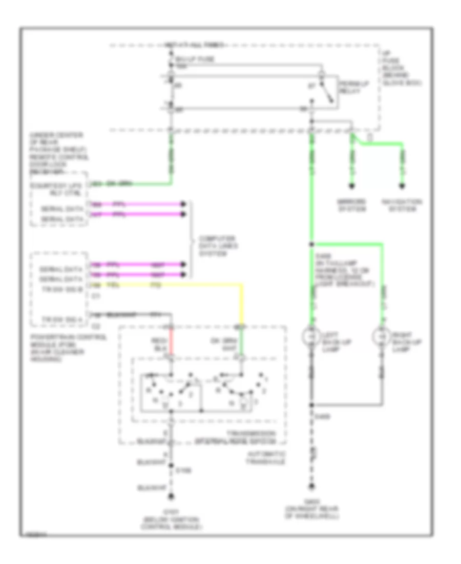
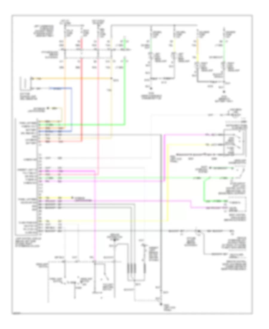
Back-up Lamps Wiring Diagram for Buick Park Avenue 2005
List of elements for Back-up Lamps Wiring Diagram for Buick Park Avenue 2005:
- (under center of rear package shelf) remote control door lock receiver
- Automatic transaxle
- B/u lp fuse 10a
- Computer data lines system
- Courtesy lps rly ctrl
- G101 (below ignition control module)
- G400 (on right rear of wheelwell)
- Hot at all times
- I/p fuse block (behind glove box)
- Left back-up lamp
- Mirrors system
- Navigation system
- Perim lp relay
- Powertrain control module (pcm) (in air cleaner housing)
- Right back-up lamp
- S108
- S408 (in taillamp harness, 12 cm from license light breakout)
- S409
- Serial data
- Tr sw sig a
- Tr sw sig b
- Transmission internal mode switch
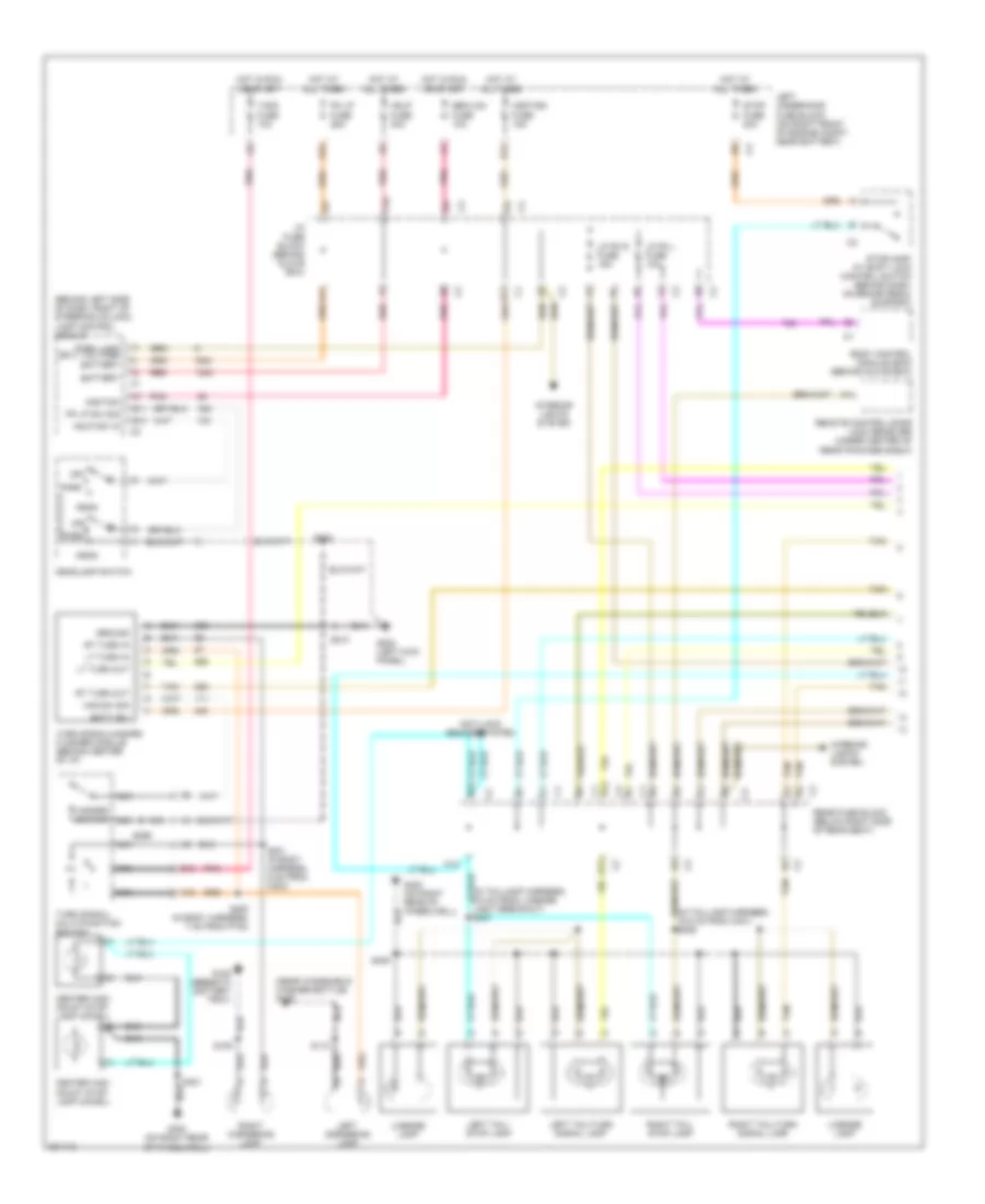
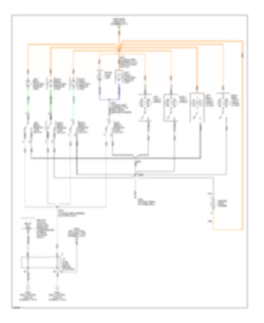
Exterior Lamps Wiring Diagram (1 of 2) for Buick Park Avenue 2005
List of elements for Exterior Lamps Wiring Diagram (1 of 2) for Buick Park Avenue 2005:
- (behind left side of dash, right of steering column)
- (in taillamp harness, 16.5 cm from c401) s406
- (in taillamp harness, 6.5 cm from license light breakout) s407
- (near windshield washer bottle) g106
- A10
- A11
- A14
- Anti-lock brakes system
- B10
- B11
- B12
- Batt (b+)
- Battery
- Body control module (bcm) (behind glove box)
- C12
- Center high mount stop lamp (chmsl)
- D12
- E11
- E12
- F10
- G105 (beneath battery tray)
- G202 (left kick panel)
- G400 (on right rear of wheelwell)
- Ground
- Haz sw sig
- Hazard switch
- Hdlp fuse 30a
- Hdlp sw in
- Head
- Headlamp switch
- Hot at all times
- Hot in run or start
- Hzdt/sg fuse 15a
- I/p fuse block (behind glove box)
- Ingition
- Interior lights system
- Lamp control module
- Left cornering lamp
- Left tail/ stop lamp
- Left tail/turn signal lamp
- Left underhood fuse block (on right front of engine compt, near battery)
- License lamp
- Lp pk l fuse 10a
- Lp pk r fuse 15a
- Lt turn in
- Lt turn out
- Nca
- Off
- Park
- Park lamp sply voltage
- Pk lp fuse 25a
- Pk lp sw sig
- Pnk
- Rear fuse block (below right side of rear seat)
- Red
- Remote control door lock receiver (under center of rear package shelf)
- Right cornering lamp
- Right tail/ stop lamp
- Right tail/turn signal lamp
- Rt turn in
- Rt turn out
- S110
- S200 (in body harness, 7 cm from p100)
- S201 (in body harness, 9 cm from c203)
- S203
- S210
- S299
- S401
- S409
- Sbm/lcm fuse 10a
- Stop fuse 20a
- Stoplamp/ at shift lock control switch (behind dash, on brake pedal support)
- T/sig fuse 10a
- Tan
- Turn signal/ multi-function switch
- Turn signal/hazard flasher module (behind center of i/p)
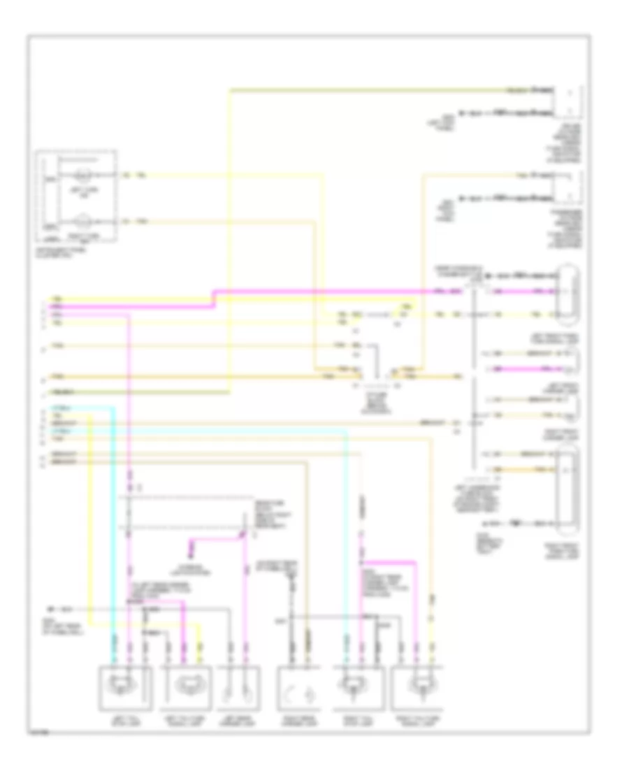
Exterior Lamps Wiring Diagram (2 of 2) for Buick Park Avenue 2005
List of elements for Exterior Lamps Wiring Diagram (2 of 2) for Buick Park Avenue 2005:
- (in left rear corner lamp harness, 17.5 cm from c404) s402
- (near windshield washer bottle) g106
- (on right rear of wheelwell) g400
- A tan
- B11
- Driver outside rearview mirror (turn signal indicator) (if equipped)
- E10
- G105 (beneath battery tray)
- G201 (right kick panel)
- G202 (left kick panel)
- G402 (on left rear of wheelwell)
- Gnd
- I/p fuse block (behind glove box)
- Instrument panel cluster (ipc)
- Interior lights system
- Left front marker lamp
- Left front park/ turn signal lamp
- Left rear marker lamp
- Left tail/ stop lamp
- Left tail/turn signal lamp
- Left turn ind
- Left underhood fuse block (on right front of engine compt, near battery)
- Logic
- Nca
- Passenger outside rearview mirror (turn signal indicator) (if equipped)
- Rear fuse block (below right side of rear seat)
- Right front marker lamp
- Right front park/turn signal lamp
- Right rear marker lamp
- Right tail/ stop lamp
- Right tail/turn signal lamp
- Right turn ind
- S101
- S102
- S205
- S208
- S400
- S401
- S403 (in right rear corner lamp harness, 17.5 cm from c405)
- S404
- S405
- Tan
GROUND DISTRIBUTION
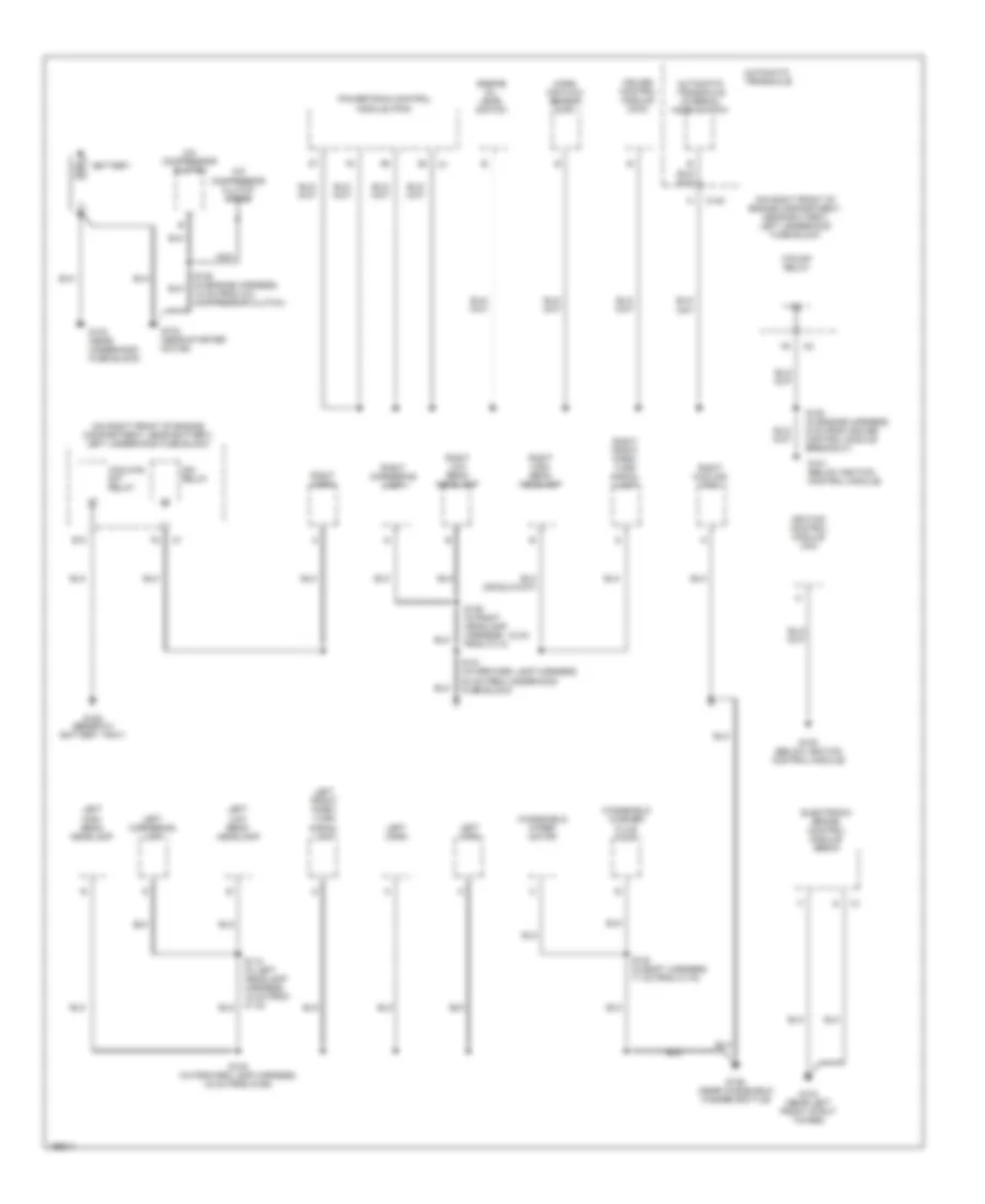
Ground Distribution Wiring Diagram (1 of 3) for Buick Park Avenue 2005
List of elements for Ground Distribution Wiring Diagram (1 of 3) for Buick Park Avenue 2005:
- (on right front of engine compartment, near battery) left underhood fuse block
- A/c compressor clutch
- A/c compressor clutch diode
- Automatic transaxle
- Automatic transaxle internal mode switch
- Battery
- C100
- Coolfan s/p relay
- Cruise control module (ccm)
- E10
- Electronic brake control module (ebcm)
- Engine oil level switch
- F/pump relay
- G100 (below ignition control module)
- G101 (below ignition control module)
- G102 (near starter motor)
- G103 (near underhood fuse block)
- G104 (near left front strut tower)
- G105 (beneath battery tray)
- G106 (near windshield washer bottle)
- Ign relay
- Ignition control module (icm)
- Left cornering lamp
- Left front park/ turn signal lamp
- Left high beam headlamp
- Left horn
- Left low beam headlamp
- Mass air flow sensor (maf)
- Nca
- Powertrain control module (pcm)
- Right cooling fan
- Right cornering lamp
- Right front park/ turn signal lamp
- Right high beam headlamp
- Right horn
- Right low beam headlamp
- S100 (in body harness, 17 cm from c115)
- S101 (in forward lamp harness, 54 cm from underhood fuse block)
- S102 (in forward lamp harness, 33 cm from g106)
- S106 (in engine harness, 18 cm from a/c compressor clutch)
- S108 (in engine harness, 6 cm from cruise control module breakout)
- S109 (in right headlamp harness, 15 cm from c114)
- S110 (in left headlamp harness, 15 cm from c112)
- Windshield washer fluid pump
- Windshield wiper motor
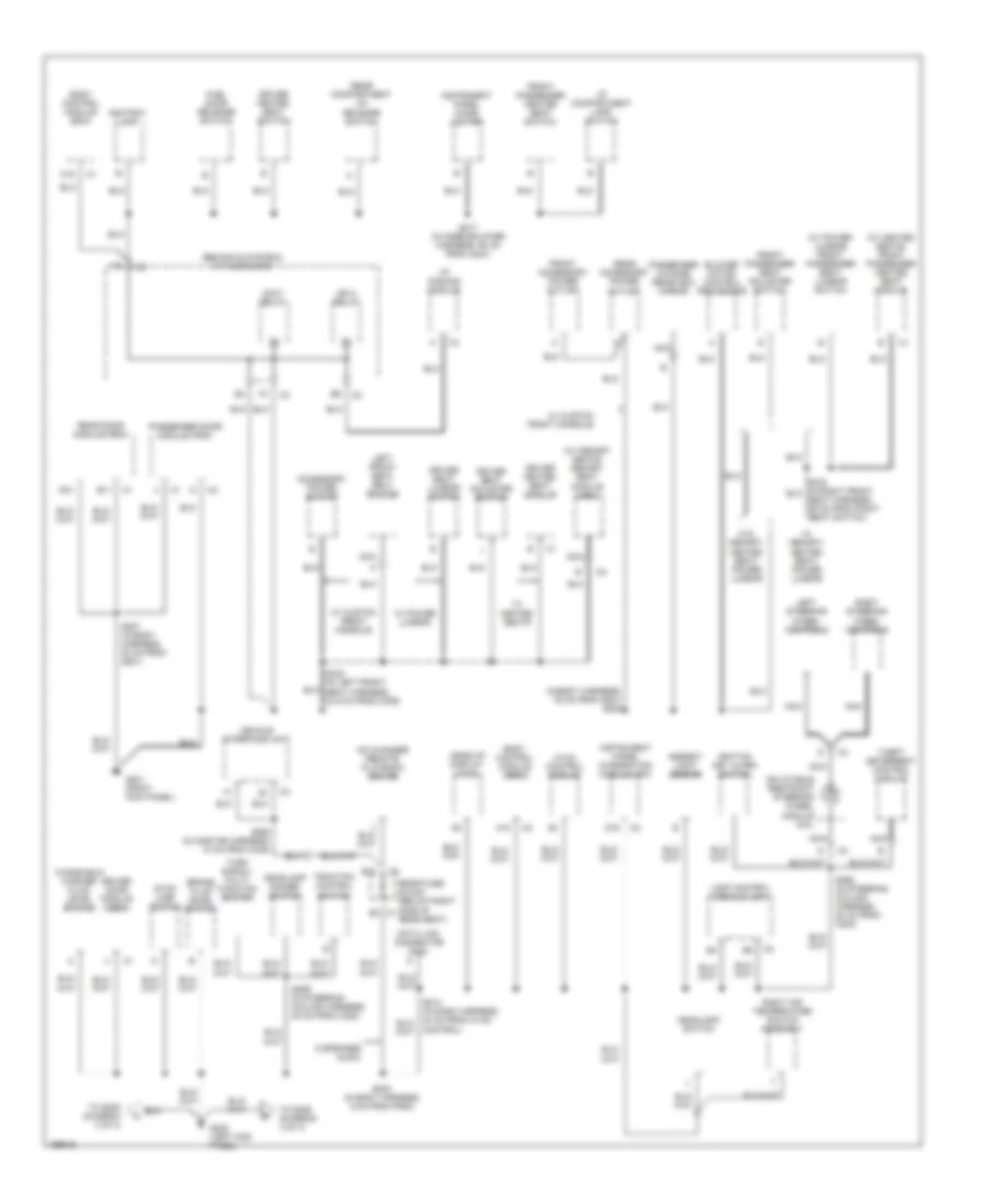
Ground Distribution Wiring Diagram (2 of 3) for Buick Park Avenue 2005
List of elements for Ground Distribution Wiring Diagram (2 of 3) for Buick Park Avenue 2005:
- (behind glove box) i/p fuse block
- (in body harness, 35 cm from g201) s208
- (w/ heated seats) front passenger heated seat module
- (w/ memory seats) memory seat module (msm)
- (w/ power lumbar) front passenger seat lumbar switch
- 6 speaker audio
- A11 a11
- A12
- Accessory power outlet
- Accy relay
- Ambient light sensor
- Ashtray lamp
- B10
- B11
- Blower motor control processor
- Body control module (bcm)
- Brake fluid level switch
- C1 b3
- C16
- Cd changer remote playback device
- Control)
- D16
- Data link connector (dlc)
- Driver door module (ddm)
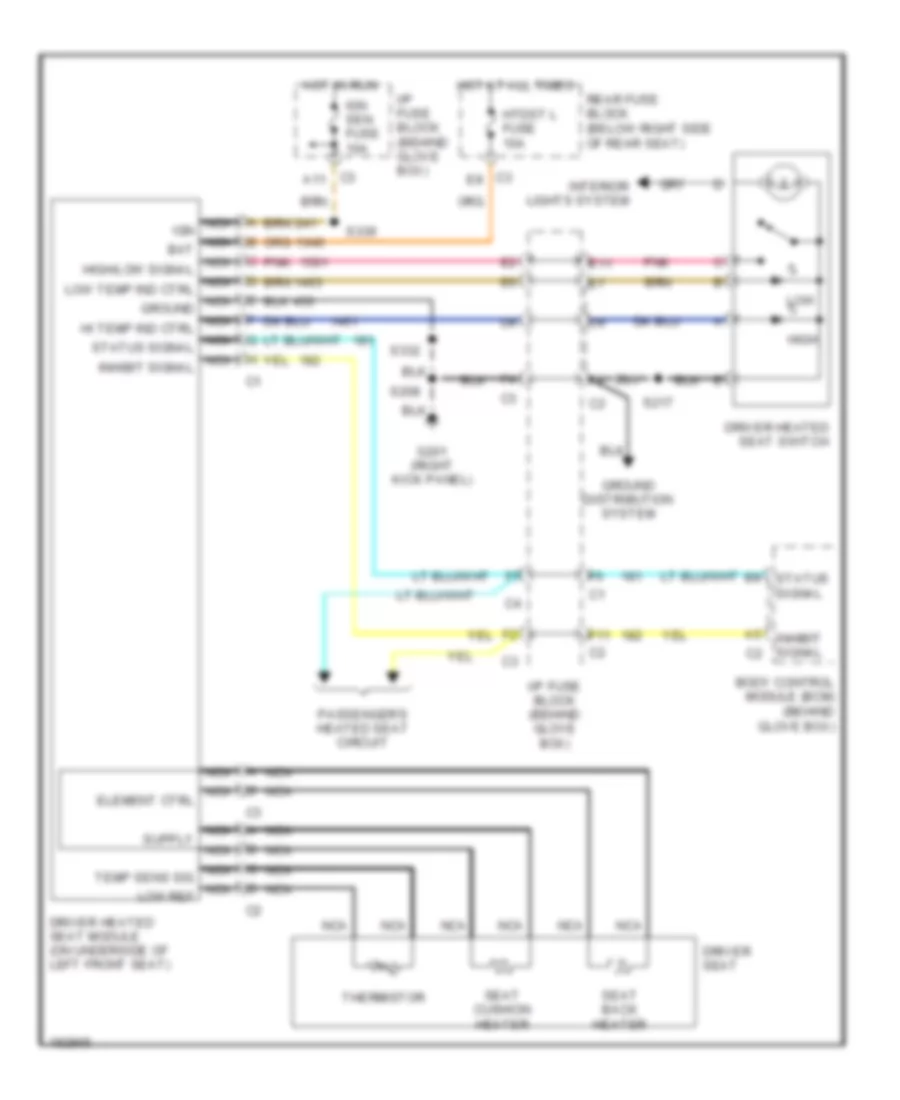
- Driver heated seat module
- Driver heated seat switch
- Driver seat adjuster switch
- Driver seat lumbar switch
- Front accessory power outlet
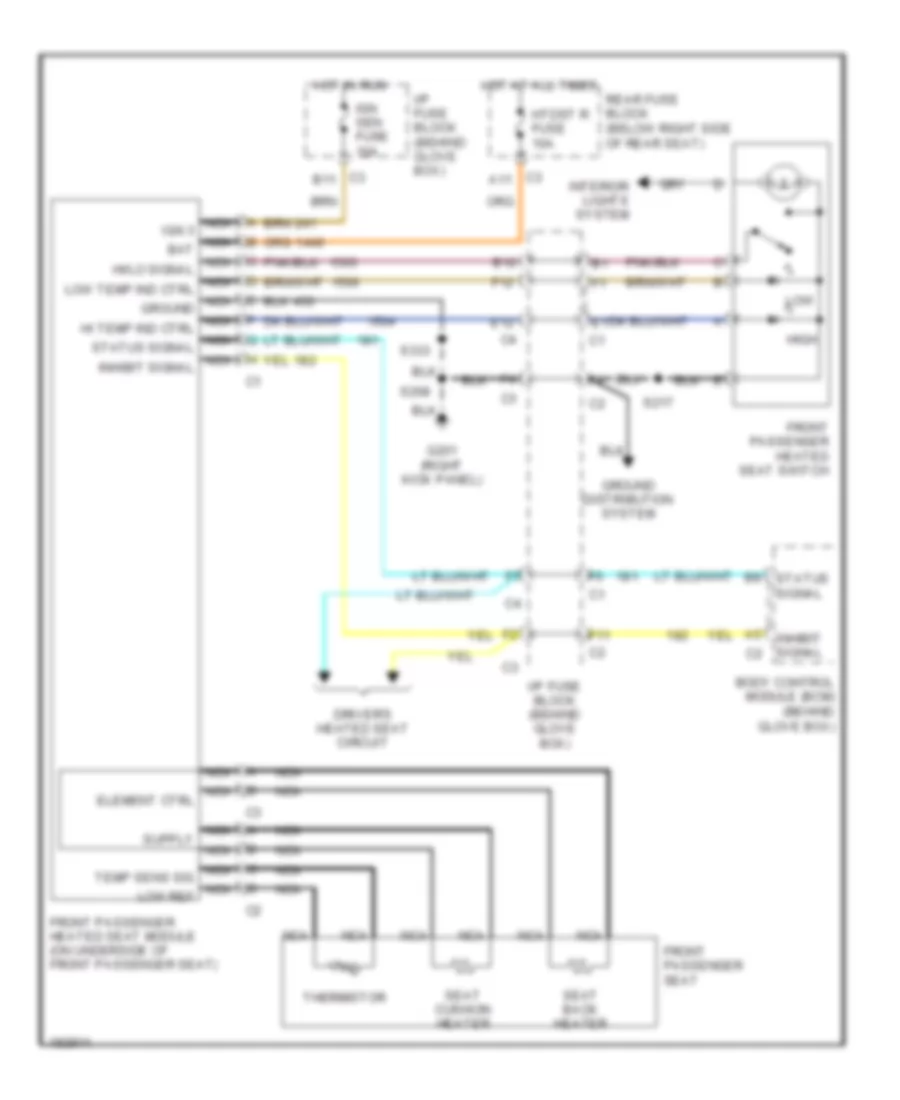
- Front passenger heated seat switch
- Front passenger seat adjuster switch
- Fuel door release switch
- G201 (right kick panel)
- G202 (left kick panel)
- Head-up display (hud)
- Headlamp dimmer switch
- Headlamp switch
- Hvac control module
- I/p compartment lamp switch
- I/p dimming module
- Ign 3 relay
- Ignition key alarm switch
- Inflatable restraint steering wheel module coil
- Instrument panel cigar lighter
- Instrument panel integration module (ipm)
- Lamp control module (lcm)
- Left front seat belt switch
- Left steering wheel controls
- Nca
- Passenger door module (pdm)
- Passenger outside rearview mirror
- Rear accessory power outlet
- Rear compartment lid release switch
- Rear door module (rdm)
- Rear fuse block (below right side of rear seat)
- Right air temperature switch assembly
- Right steering wheel controls
- S203 (in body harness, 6 cm from p500)
- S207 (in body harness, 30 cm from g201)
- S217 (in knee bolster harness, 94 cm from c204)
- S298 (in steering column harness, 20 cm from c202)
- S299 (in steering column harness, 20 cm from c202)
- S332 (in left front seat harness, 24.5 cm from c309)
- S360 (in onstar harness, 10 cm from c345)
- Stop lamp switch
- Theft deterrent control module
- To s205 (diagram 3 of 3)
- To s206 (diagram 3 of 3)
- Traction control switch
- Turn signal/ multi- function switch
- Vehicle interface unit
- W/ custom front console
- W/ heated seats
- W/ memory/ heated seat/ power lumbar
- W/ power lumbar
- W/o memory/ heated seat/ power lumbar
- Windshield washer fluid level switch
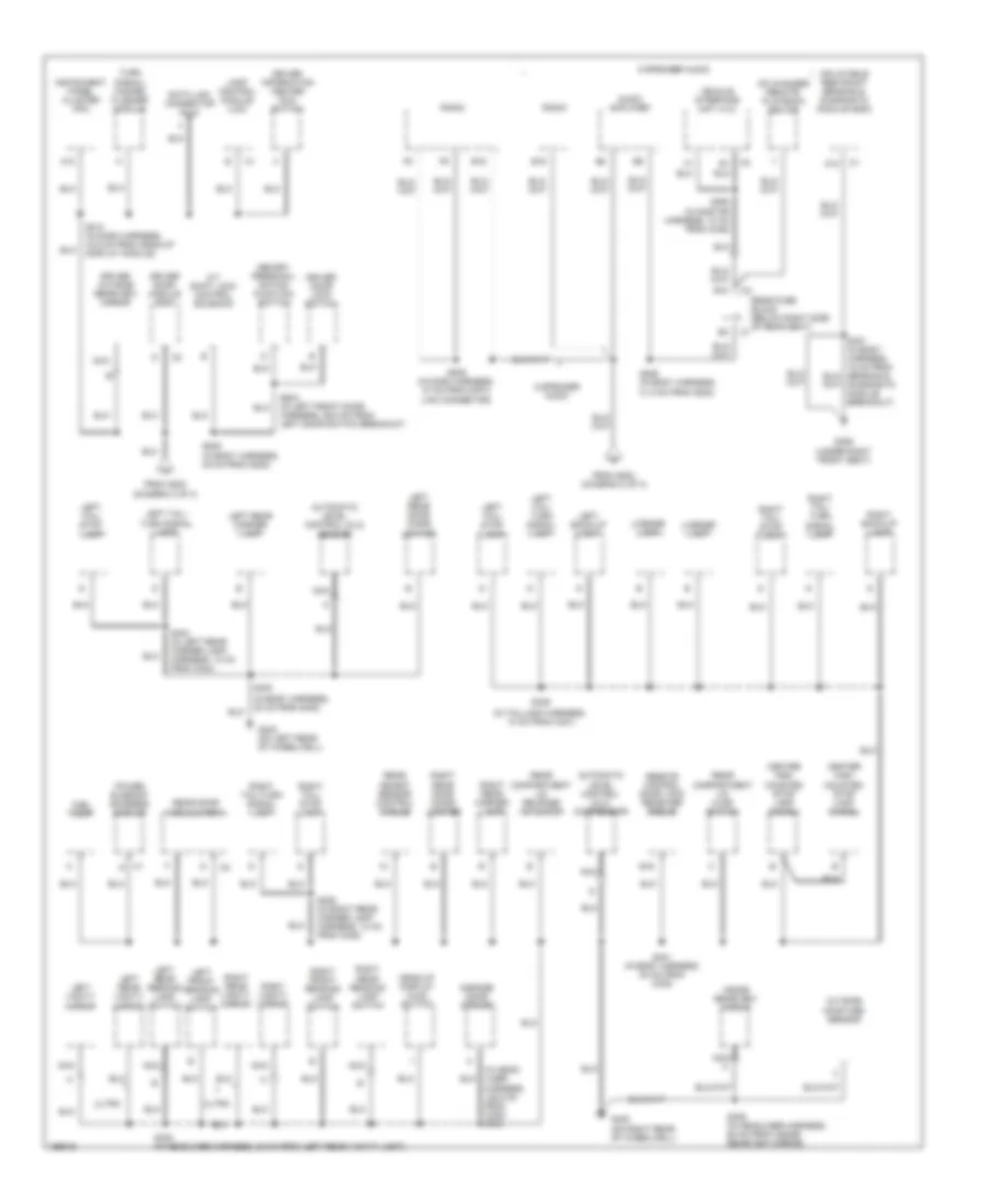
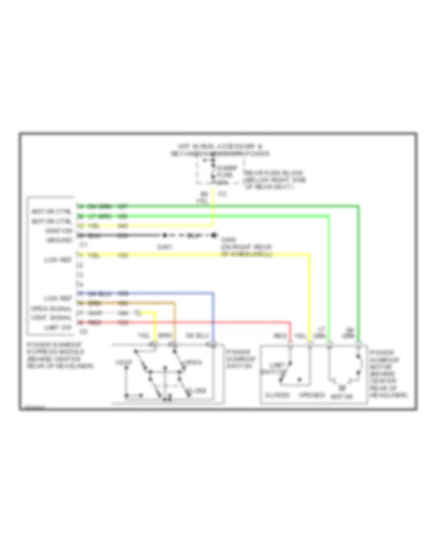
Ground Distribution Wiring Diagram (3 of 3) for Buick Park Avenue 2005
List of elements for Ground Distribution Wiring Diagram (3 of 3) for Buick Park Avenue 2005:
- (diagram 2 of 3)
- (in body harness, 30 cm from g402)
- (in head- liner harness, 128.5 cm from c305) s303
- (in onstar harness, 10 cm from c345)
- (in taillamp harness, 10 cm from c401)
- 6 speaker audio
- 9 speaker audio
- A/t shift lock control solenoid
- A12
- A18
- Audio amplifier
- Automatic level control (alc) compressor
- Automatic level control (alc) sensor
- B10
- B16
- C1 d
- Cd changer remote playback device
- Center high mounted stop lamp (chmsl)
- Data link connector (dlc)
- Diagnostic module breakout)
- Driver door lock switch
- Driver door module (ddm)
- Driver information center (dic) switch
- Driver outside rearview mirror
- E16
- From g202
- From g202 (diagram 2 of 3)
- Fuel pump
- G306 (under right front seat)
- G400 (on right rear of wheelwell)
- G402 (on left rear of wheelwell)
- Garage door opener
- Head-up display (hud) switch
- Inflatable restraint sensing & diagnostic module (sdm)
- Inside rearview mirror
- Instrument panel cluster (ipc)
- Lamp control module (lcm)
- Left back-up lamp
- Left front reading lamp switch
- Left rear door cigar lighter
- Left rear marker lamp
- Left rear reading lamp switch
- Left rear vanity mirror
- Left tail/ stop lamp
- Left tail/ turn signal lamp
- Left vanity mirror
- License lamp
- Memory personal- ization function switch
- Nca
- Outside moisture sensor
- Power sunroof express module
- Radio
- Rear compartment lid ajar switch
- Rear compartment lid release actuator
- Rear door module (rdm)
- Rear fuse block (below right side of rear seat)
- Rear object sensor control module
- Remote control door lock receiver (rcdlr)
- Right back-up lamp
- Right front reading lamp switch
- Right rear door cigar lighter
- Right rear marker lamp
- Right rear reading lamp switch
- Right rear vanity mirror
- Right tail/ stop lamp
- Right tail/ turn signal lamp
- Right tail/turn signal lamp
- Right vanity mirror
- S205 (in body harness, 38 cm from g202)
- S206 (in body harness, 31.5 cm from g202)
- S209 (in dash harness, 47 cm from data link connector)
- S210 (in dash harness, 18.5 cm from head-up display module)
- S306 (in headliner harness, 58 cm from inside rearview mirror)
- S308 (in headliner harness, 20 cm from left rear vanity light)
- S360
- S400
- S401 (in body harness, 80 cm from c305)
- S404 (in left rear corner lamp harness, 10 cm from c404)
- S405 (in right rear corner lamp harness, 10 cm from c405)
- S409
- S503 (in left front door harness, 29.5 cm from left door switch breakout)
- Turn signal/ hazard flasher module
- Ultra
- Vehicle interface unit (viu)
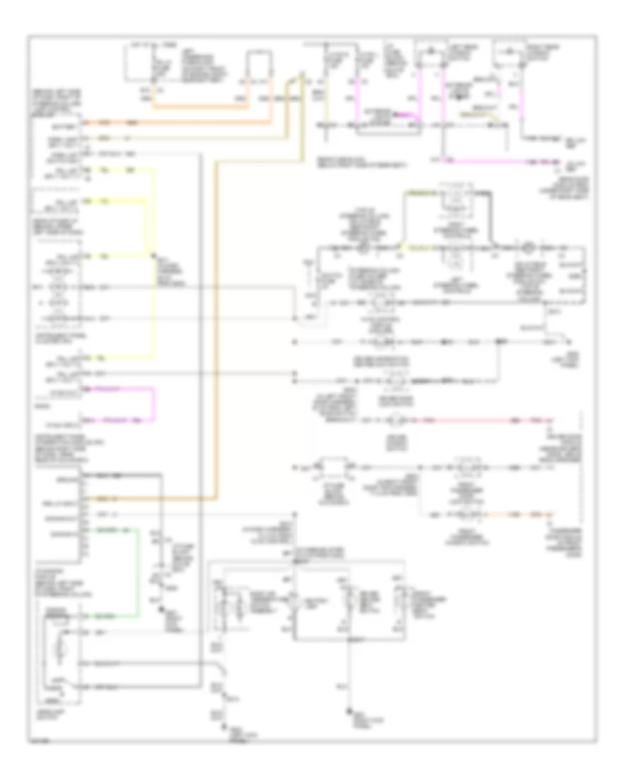
HEADLIGHTS
Headlights Wiring Diagram for Buick Park Avenue 2005
List of elements for Headlights Wiring Diagram for Buick Park Avenue 2005:
- (near windshield washer bottle)
- A10
- A11
- A12
- Alarm sig
- Ambient light in
- Ambient light sensor (on top center of dash)
- B10
- B11
- B12
- Battery
- Body control module (bcm) (behind glove box)
- C12
- D10
- Daytime running lamp (drl) resistor
- Drl res sply
- E12
- E14
- Exterior lights system
- F10
- Flash -to- pass switch
- Flash pass sig
- G105 (beneath battery tray)
- G106
- G202 (left kick panel)
- Gnd
- Ground distribution system
- Hdhibml fuse 10a
- Hdhibmr fuse 10a
- Hdlobml fuse 10a
- Hdlobmr fuse 10a
- Hdlp alarm signal
- Hdlp fuse 30a
- Hdlp sw in
- Hdlps off sig
- Hdlps off sig c1
- Head
- Headlamp dimmer switch
- Headlamp switch
- Hi-beam ind
- Hi-beam sw
- Hi-beam volt
- High beam ind
- High beam switch
- Hot at all times
- Hot in run or start
- I/p fuse block (behind glove box)
- Ign (r/s) in
- Instrument panel cluster (ipc)
- Interior lights system
- Lamp control module (behind left side of dash, right of steering column)
- Left high beam headlamp
- Left low beam headlamp
- Left underhood fuse block (on right front of engine compt, near battery)
- Logic
- Low-beam
- Nca
- Off
- P gear in
- Panel lmp feed
- Park
- Park lamp switch
- Park lmp feed
- Pk lp fuse 25a
- Pk lp sw in
- Pnk
- Red
- Remote control door lock receiver (under center of rear package shelf)
- Right high beam headlamp
- Right low beam headlamp
- S101
- S102
- S109
- S110
- S203
- S210
- S213
- S215
- S299
- Sbm lcm fuse 10a
- Shift interlock system
- Stoplamp/at shift lock control switch (behind dash, on brake pedal support)
- Tan
- Twilight sentinel switch
- Twlt delay
- Vehicle interface unit (on right front of trunk, attached to seat back brace)
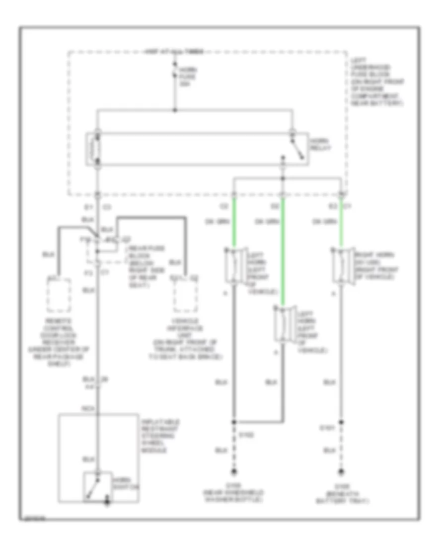
HORN
Horn Wiring Diagram for Buick Park Avenue 2005
List of elements for Horn Wiring Diagram for Buick Park Avenue 2005:
- C1 e2
- E11
- F10
- G105 (beneath battery tray)
- G106 (near windshield washer bottle)
- Horn fuse 30a
- Horn relay
- Horn switch
- Hot at all times
- Inflatable restraint steering wheel module
- Left horn (left front of vehicle)
- Left underhood fuse block (on right front of engine compartment, near battery)
- Nca
- Rear fuse block (below right side of rear seat)
- Remote control door lock receiver (under center of rear package shelf)
- Right horn (w/ u06) (right front of vehicle)
- S101
- S102
- Vehicle interface unit (on right front of trunk, attached to seat back brace)
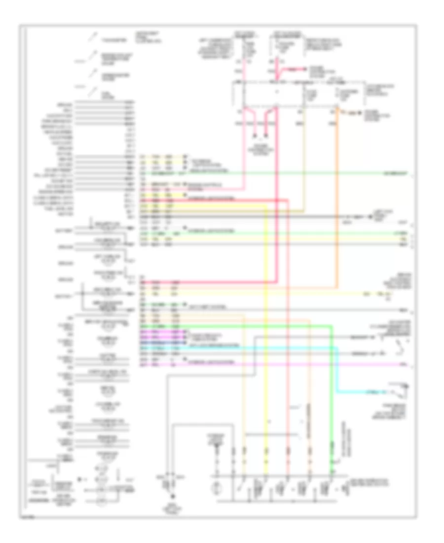
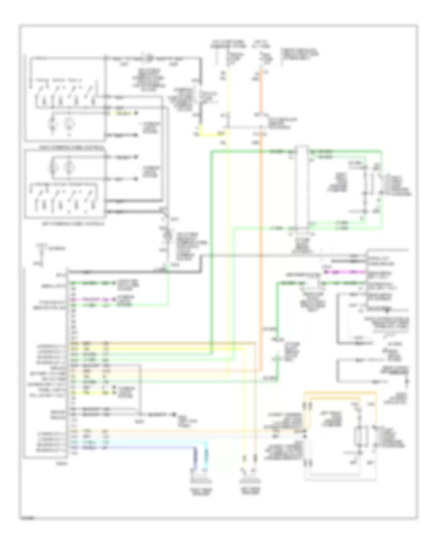
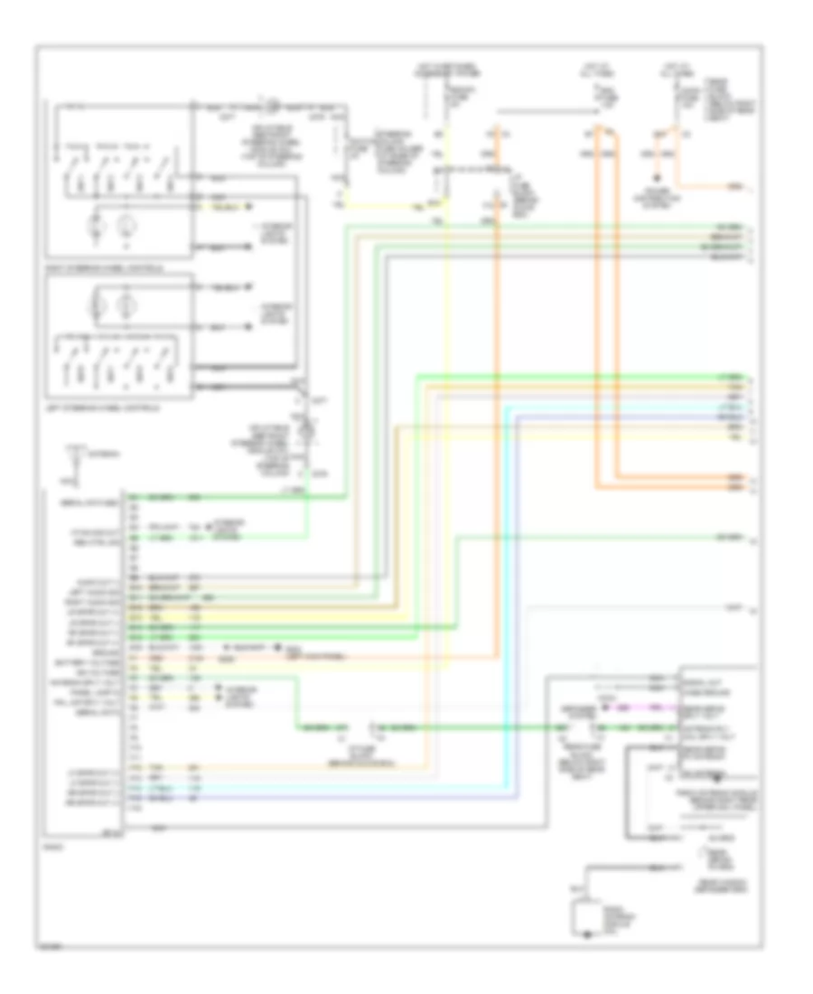
INSTRUMENT CLUSTER
Instrument Cluster Wiring Diagram (1 of 2) for Buick Park Avenue 2005
List of elements for Instrument Cluster Wiring Diagram (1 of 2) for Buick Park Avenue 2005:
- (behind glove box) body control module (bcm)
- (left kick panel) g202
- (on master cylinder reservoir) brake fluid level switch
- A10
- A11
- A12
- A13
- A14
- A15
- A16
- A17
- Abs ind
- Air bag ind
- Anti-lock brakes system
- Anti-theft system
- B10
- B11
- B12
- B13
- B14
- B15
- B16
- B17
- Base cluster
- Battery
- Brake fluid lvl
- Brake ind
- Check oil level ind
- Class 2 (ebcm)
- Class 2 (pcm)
- Class 2 (sdm)
- Class 2 serial data
- Computer data lines system
- Cruise ind
- Cstr/sbm fuse 10a
- Dic fuel
- Dic gauge sig
- Dic odo
- Dic set/reset
- Dic/met sig
- Driver information center
- Driver information center (dic) switch
- E/m switch
- Engine controls system
- Engine coolant temperature gauge
- Engine speed sig
- Exterior lights system
- Fuel gauge
- Fuel level sig
- Fuel switch
- G202 (left kick panel)
- Ground
- Headlights system
- High beam ind
- Hot at all times
- Hot in run
- Hot in run or start
- Hot in unlock, run or start
- Hud clock
- Hud data sig
- Hud strobe
- Hvac fuse 10a
- I/p fuse block (behind glove box)
- Ign
- Ign 3
- Ignition
- Ignition 1
- Illumination
- Ind
- Instrument panel cluster (ipc)
- Interior lights system
- Left turn ind
- Left underhood fuse block (on right front of engine compt, near battery)
- Logic
- Low fuel ind
- Low fuel ind control
- Message display
- Odometer
- Odometer switch
- P r n d 3 2 1
- Park brake sw
- Park brake switch (on top of park brake assembly)
- Pcm/cru fuse 10a
- Pnk
- Pnl lmp sply volt 3
- Power distribution system
- Rear fuse block (below right side of rear seat)
- Red
- Right turn ind
- S203
- S210
- Seat belt ind
- Security ind
- Service engine soon ind
- Service vehicle soon
- Smb/ lcm fuse 10a
- Speedometer gauge
- Switch gauge
- Switch reset
- Tachometer
- Tan
- Traction off ind
- Trip a/b
- Up-level cluster
- Vehicle speed
- Volt ind
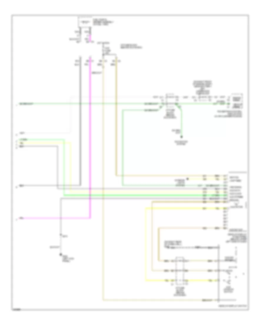
Instrument Cluster Wiring Diagram (2 of 2) for Buick Park Avenue 2005
List of elements for Instrument Cluster Wiring Diagram (2 of 2) for Buick Park Avenue 2005:
- (on right front of engine compt, near battery) left underhood fuse block
- (on right rear of wheelwell) g400
- A11
- B10
- C1 b9
- C11
- C2 e4
- C3 e9
- C4 b4
- D11
- Down
- E11
- Engine speed
- Fuel pump & sender assembly (in fuel tank)
- G202 (left kick panel)
- Ground
- Head-up display (if equipped) (behind upper left side of dash)
- Head-up display switch
- Hot in run
- Hud clock
- Hud data
- Hud dim switch
- Hud fuse 10a
- Hud motor
- Hud strobe
- Hud sw out
- Hud up/down switch
- I/p fuse block (behind glove box)
- Ignition
- Interior lights system
- Lamp feed
- Navigation system
- Nca
- Powertrain control module (pcm) (in air cleaner housing)
- S213
- S303
- Vehicle speed
- Vss signal
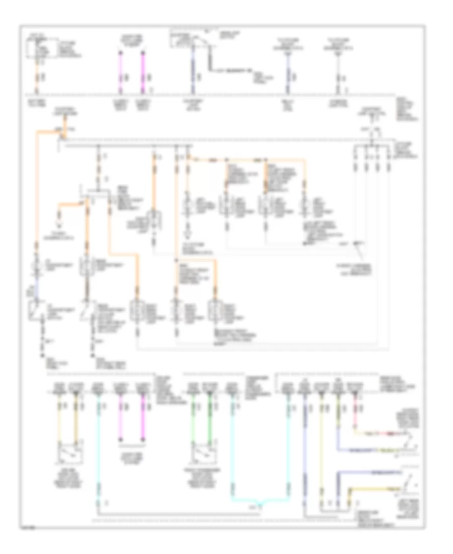
INTERIOR LIGHTS
Courtesy Lamps Wiring Diagram (1 of 2) for Buick Park Avenue 2005
List of elements for Courtesy Lamps Wiring Diagram (1 of 2) for Buick Park Avenue 2005:
- (in body harness, 32 cm from c301 breakout)
- (in right rear door) right rear door lock actuator
- A10 c4
- A3 c1
- B10 c4
- Battery voltage
- Body control module (bcm) (behind glove box)
- C10
- C15
- Class 2 serial data
- Class 2 serial data c1
- Computer data lines system
- Courtesy lamp low ctrl c14 c1
- Courtesy lamp power d1
- Courtesy lamp sw sig
- Courtesy lamps switch
- D1 c2
- D10
- D13
- D4 c1
- D9 c4
- Door open sw sig c
- Door serial data
- Door serial data a12
- Door serial data c1
- Driver door lock actuator (rear of right front door)
- Driver door module (inside driver's door, above radio speaker)
- E6 c2
- Front passenger door lock actuator (rear of right front door)
- G201 (right kick panel)
- G202 (left kick panel)
- G400 (on right rear of wheelwell)
- Headlamp switch
- Hot at all times
- I/p compartment lamp
- I/p compartment lamp switch
- I/p fuse block (behind glove box)
- Interior lamp ctrl
- Left footwell courtesy lamp
- Left front door courtesy lamp
- Left rear door courtesy lamp
- Left rear door lock actuator (in left rear door)
- Lf door sw low ref a c3
- Lr door open sw sig a7
- Lr door sw low ref a9
- Passenger door module (in front passenger's door)
- Rear compartment lamp
- Rear compartment lid ajar switch (on center of rear compt, on latch)
- Rear door module (rdm) (under right side of rear seat)
- Rear fuse block (below right side of rear seat)
- Red
- Red a
- Relay coil ctrl
- Rf door sw low ref a c3
- Right footwell courtesy lamp
- Right front door courtesy lamp
- Right rear door courtesy lamp
- Rr door open sw sig a5
- Rr door sw low ref a3 c1
- S217
- S310 (in body harness, 22 cm from c301 breakout)
- S311
- S401
- S600 (in right front door trim harness, 61 cm from c602)
- Sbm fuse 10a
- Tan
- Tan d
- To i/p fuse block (diagram 2 of 2)
- To s301 (diagram 2 of 2)
Courtesy Lamps Wiring Diagram (2 of 2) for Buick Park Avenue 2005
List of elements for Courtesy Lamps Wiring Diagram (2 of 2) for Buick Park Avenue 2005:
- From body control module (diagram 1 of 2)
- From left footwell courtesy lamp (diagram 1 of 2)
- From rear fuse block (diagram 1 of 2)
- G400 (on right rear of wheelwell)
- Garage door opener
- I/p fuse block (behind glove box) c1
- Left front courtesy/ reading lamp
- Left front reading lamp switch
- Left rear courtesy/ reading lamp
- Left rear reading lamp switch nca
- Left rear vanity mirror (ultra)
- Left vanity mirror
- Nca
- Office work lamp
- Relay coil ctrl b1
- Remote control door lock receiver (under center of rear package shelf)
- Right front courtesy/ reading lamp
- Right front reading lamp switch
- Right rear courtesy/ reading lamp
- Right rear reading lamp switch
- Right rear vanity mirror (ultra)
- Right vanity mirror
- S301 (in headliner harness, 51 cm from sun roof switch)
- S302 (in headliner harness, 60 cm from c307)
- S303
- S304 (in headliner harness, 47 cm from inside rearview mirror)
- S308
Instrument Illumination Wiring Diagram for Buick Park Avenue 2005
List of elements for Instrument Illumination Wiring Diagram for Buick Park Avenue 2005:
- (behind left side of dash, right of steering column)
- (behind left side of dash, right of steering column) lamp control module
- (behind right side of dash, near rear of glove box)
- (in knee bolster, 87.5 cm from c204) s216
- (top of steering column) inflatable restraint steering wheel module coil
- A11
- A12
- A14
- A8 pnl lmp sply volt 3
- Ashtray lamp
- B11
- B16
- Battery
- C2 i/p fuse block (behind glove box) c3
- C3 a2
- D14
- Dimming in
- Dimming out
- Dimming switch
- Driver door lock switch
- Driver door module (inside driver's door, above radio speaker)
- Driver heated seat switch
- Driver information center (dic) switch
- Driver window switch
- E12
- Exterior lights system
- F4 pnl lmp sply volt 1
- F5 pnl lmp sply volt 3
- Front passenger door lock switch
- Front passenger heated seat switch
- Front passenger window switch
- G201 (right kick panel)
- G202 (left kick panel)
- Ground
- Head
- Head-up display (behind upper left side of dash)
- Headlamp switch
- Hot at all times
- Hvac control module (6 bulbs)
- I/p dimming module
- I/p fuse block (behind glove box)
- Inflatable restraint steering wheel module coil (top of steering column)
- Instrument panel cluster (ipc)
- Instrument panel integration module (ipm)
- Left rear window switch
- Left steering wheel controls
- Left underhood fuse block (on right front of engine compt, near battery)
- Lp pk l fuse 10a
- Lp pk r fuse 15a
- Lr low ref c1
- Nca
- Off
- Park
- Park lamp sply volt
- Park lmp switch sig
- Passenger door module (in front passenger's door)
- Pk lp fuse 25a
- Pnk
- Pnl lmp sply volt 3
- Prk lp input
- Radio
- Rear door module (rdm) (under right side of rear seat)
- Rear fuse block (below right side of rear seat)
- Right air temperature switch assembly
- Right rear window switch
- Right steering wheel controls
- Rr low ref
- S205
- S208
- S210
- S211 (in dash harness, 35 cm from g202)
- S212 (in dash harness, 51.5 cm from hvac control)
- S213
- S217
- S298
- S502 (in left front door harness, 23 cm from left door switch breakout)
- S503
- S602 (in right front door trim harness, 71.5 cm from c602)
- Steering column fuse holder (at base of steering column)
- Switch fuse 2a
- Vf dim input
- Vf dim out
MEMORY SYSTEMS
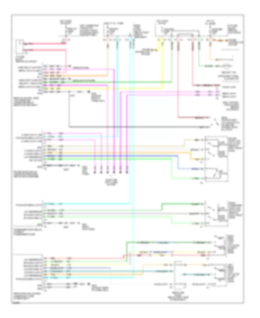
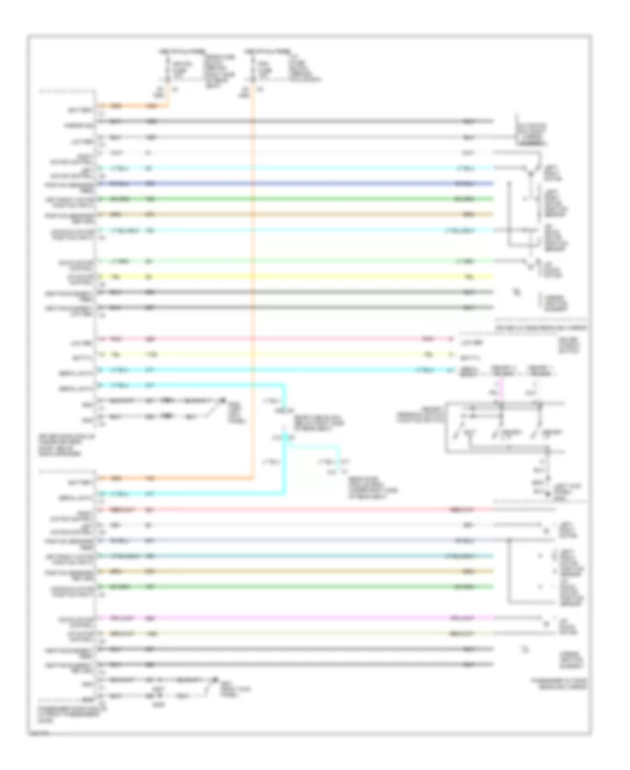
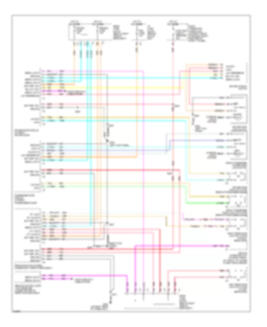
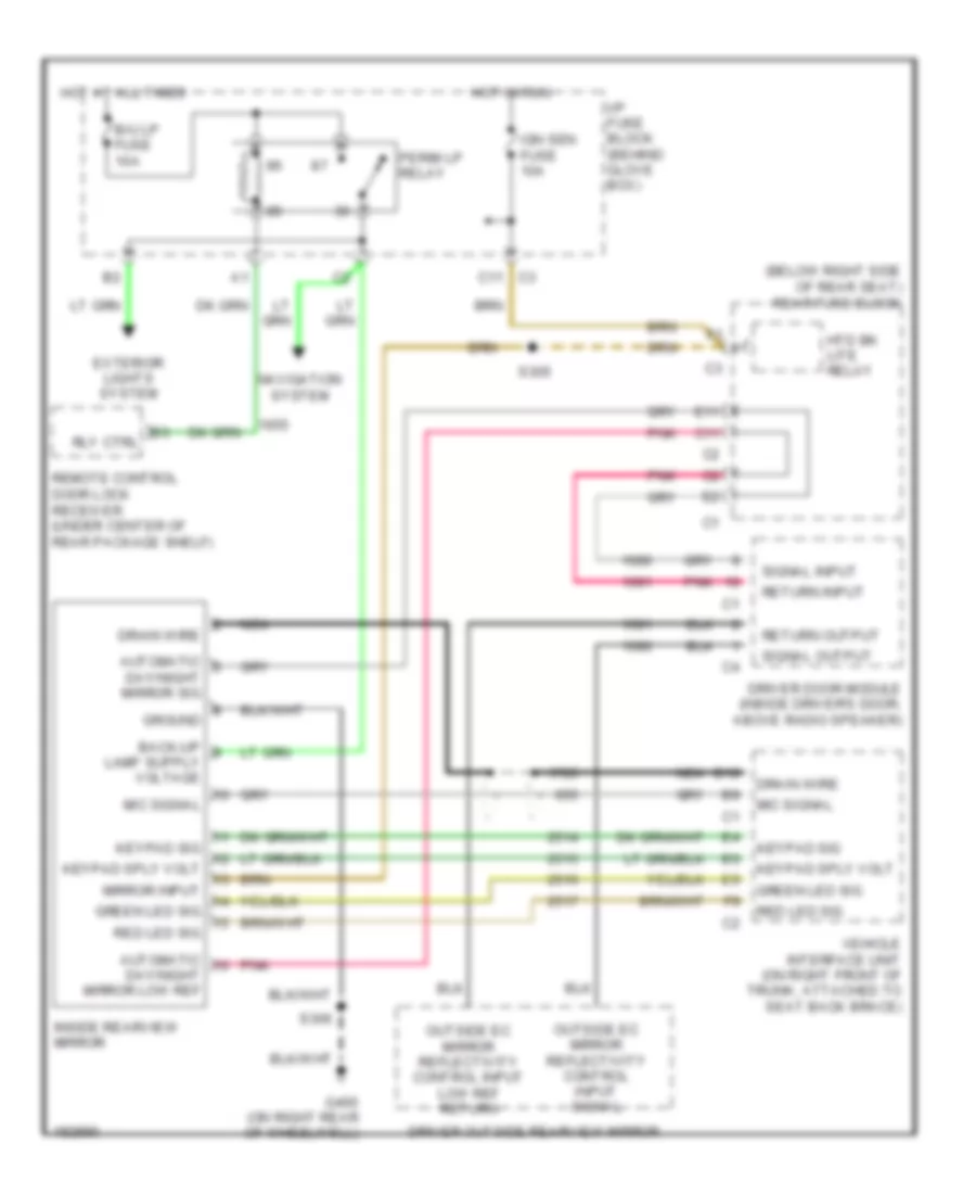
Memory Mirrors Wiring Diagram for Buick Park Avenue 2005
List of elements for Memory Mirrors Wiring Diagram for Buick Park Avenue 2005:
- (left kick panel) g202
- Automatic day/night mirror element
- Batt(+)
- Battery
- C1 a12
- C10
- Control c5
- Down motor control
- Driver door module (inside driver's door, above radio speaker)
- Driver outside rearview mirror
- Driver window switch
- Drvmdl fuse 10a
- Exit
- G201 (right kick panel)
- G202 (left kick panel)
- Gnd
- Heating element feed
- Heating element low ref
- Heating element return
- Hot at all times
- I/p fuse block (behind glove box)
- Left motor control
- Left/ right motor
- Left/ right motor position sensor
- Left/right motor position input
- Low ref
- Memory
- Memory 1 sw sig
- Memory 2 sw sig
- Memory/ personalization function switch
- Mirror heating element
- Mirror sig
- Passenger door module (in front passenger's door)
- Passenger outside rearview mirror
- Pdm fuse 10a
- Pnk
- Postion sensors feed
- Postion sensors return
- Rear door module (rdm) (under right side of rear seat)
- Rear fuse block (behind right side of rear seat)
- Rear fuse block (below right side of rear seat)
- Right motor control
- S203
- S205
- S207
- S208
- S503
- Serial data
- Up motor
- Up/ down motor
- Up/ down motor position sensor
- Up/down motor position input
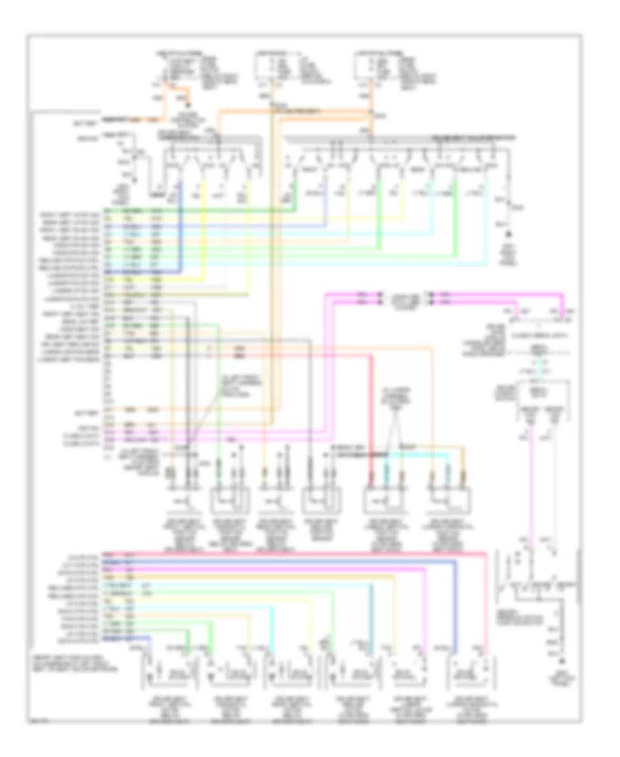
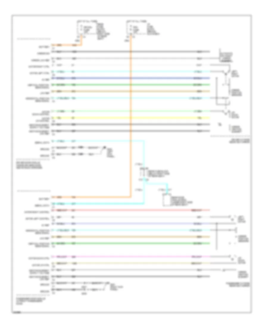
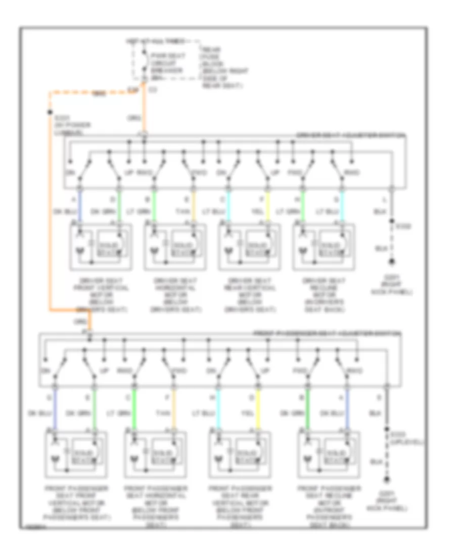
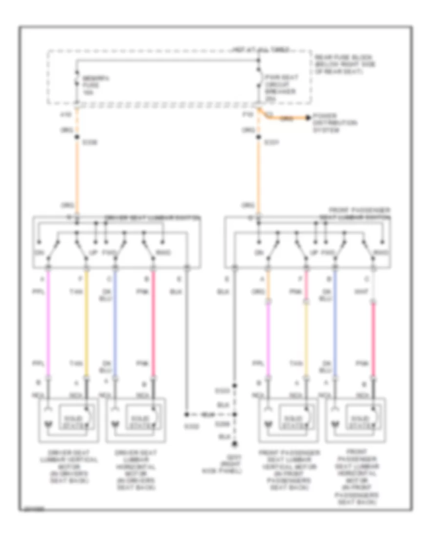
Memory Seat Wiring Diagram for Buick Park Avenue 2005
List of elements for Memory Seat Wiring Diagram for Buick Park Avenue 2005:
- (in left front seat harness, 15 cm from memory seat module)
- (in left front seat harness, 24.5 cm from c309)
- (in lumbar harness, 50 cm from c322)
- 5 volt ref
- A10
- A11
- Battery
- C10
- C11
- C12
- C13
- C14
- C15
- C16
- Class 2 data
- Class 2 serial data
- Computer data lines system
- D10
- D11
- D12
- D13
- D14
- D15
- D16
- Driver door module (inside driver's door, above radio speaker)
- Driver seat adjuster switch
- Driver seat front vertical motor (below driver's seat)
- Driver seat front vertical position sensor (below driver's seat)
- Driver seat horizontal motor (below driver's seat)
- Driver seat horizontal position sensor (below driver's seat)
- Driver seat lumbar horizontal motor (in driver's seat back)
- Driver seat lumbar horizontal position sensor (in driver's seat back)
- Driver seat lumbar switch
- Driver seat lumbar vertical motor (in driver's seat back)
- Driver seat lumbar vertical position sensor (in driver's seat back)
- Driver seat rear vertical motor (below driver's seat)
- Driver seat rear vertical position sensor (below driver's seat)
- Driver seat recline motor (in driver's seat back)
- Driver seat recline position sensor
- Driver window switch
- Drv seat recline sig
- Exit
- F10
- Front
- Front vert dn sw sig
- Front vert seat sig
- Front vert up sw sig
- Fwd
- G201 (right kick panel)
- G202 (left kick panel)
- Ground
- Horiz fwd sw sig
- Horiz rwd sw sig
- Horiz seat sig
- Hot at all times
- Hot in run
- I/p fuse block (behind glove box)
- Ign sen fuse 10a
- Ignition
- Lumbar down sw sig
- Lumbar fwd sw sig
- Lumbar hor pos sens
- Lumbar rwd sw sig
- Lumbar up sw sig
- Lumbar vert pos sens
- Mem/ rfa fuse 10a
- Memory
- Memory 1 sw sig
- Memory 2 sw sig
- Memory seat module (msm) (on underside of left front seat, on seat adjuster frame)
- Memory/ personalization function switch
- Nca
- Pnk b
- Power distribution system
- Pwr seat circuit breaker 25a
- Rear
- Rear fuse block (below right side of rear seat)
- Rear vert dn sw sig
- Rear vert seat sig
- Rear vert up sw sig
- Recline
- Recline mtr fwd ctrl
- Recline mtr rwd ctrl
- Red
- Red b
- Rwd
- S332
- S334
- S335
- S336
- S337
- S338
- S339 (w/ heated seat)
- S503
- Sens low ref
- Serial data
- Solid state
- Tan
- Tan a
NAVIGATION
Parking Assistant Wiring Diagram for Buick Park Avenue 2005
List of elements for Parking Assistant Wiring Diagram for Buick Park Avenue 2005:
- (on right rear of wheelwell) g400
- Amber center ind ctrl
- Amber center indicator
- Amber left ind ctrl
- Amber outside indicator
- Assist diagnostic connector (under right side of rear window shelf)
- B/u lp fuse 10a
- Backup lamp voltage
- Body control module (bcm) (behind glove box)
- Diagnostic input
- Engine controls system
- F12
- Ground
- Hot at all times
- Hot in run or start
- I/p fuse block (behind glove box)
- Left rear corner object sensor (on left corner of rear bumper fascia)
- Left rear middle object sensor (on left middle of rear bumper fascia)
- Left underhood fuse block (on right front of engine compt, near battery)
- Low ref
- Lr corner sensor sig
- Lr middle sensor sig
- Mirrors system
- Perim lp relay
- Pnk
- Rear fuse block (below right side of rear seat)
- Rear object sensor control module (under right side of rear window shelf)
- Rear park assist (rpa) display
- Rear park chime sig
- Rear parking a
- Red
- Red ind ctrl
- Red indicator
- Remote control door lock receiver (under center of rear package shelf)
- Right rear corner object sensor (on right corner of rear bumper fascia)
- Right rear middle object sensor (on right middle of rear bumper fascia)
- Rr corner sensor sig
- Rr middle sensor sig
- S315 (in rear park aid harness, 36.5 cm from c408)
- S316 (in rear park aid harness, 56.5 cm from c408)
- S401
- Sbm/lcm fuse 10a
- Sensor low ref
- Sensor signal
- Sensor voltage
- Telltale assy voltage
- Vss signal
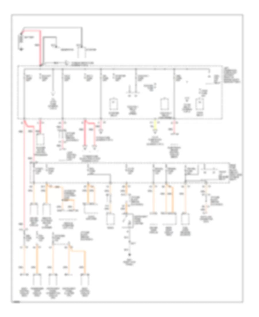
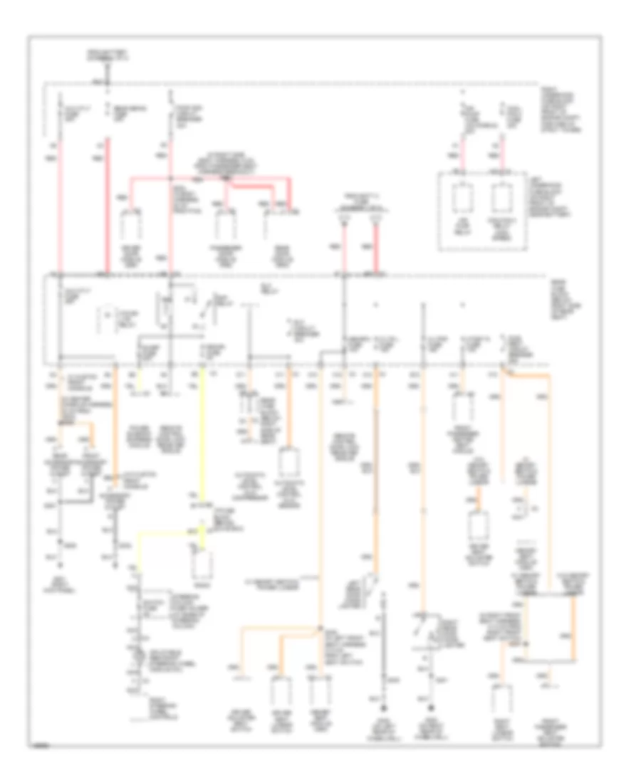
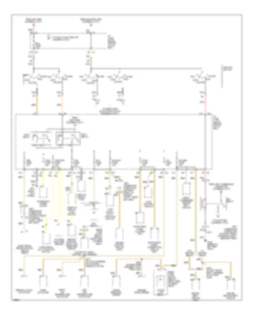
POWER DISTRIBUTION
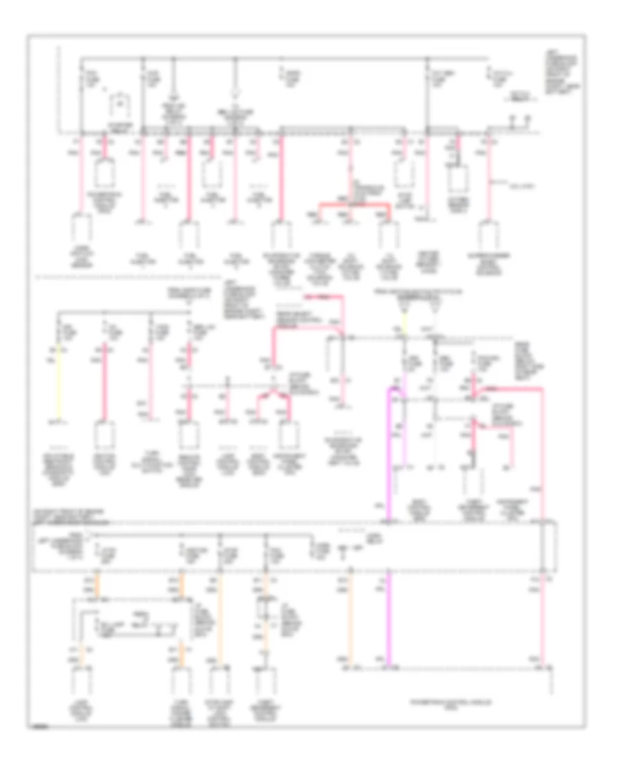
Power Distribution Wiring Diagram (1 of 4) for Buick Park Avenue 2005
List of elements for Power Distribution Wiring Diagram (1 of 4) for Buick Park Avenue 2005:
- (in onstar harness, 12 cm from c345) s361
- A10 c1
- A12
- Abs fuse 50a
- Audio amplifier
- B c1
- B10
- B12
- Bat 1 fuse 60a
- Bat 2 fuse 60a
- Battery
- Blo mot fuse 30a
- Blower motor control processor
- Body control module (bcm)
- C/ltr fuse 15a
- Cd/ph fuse 10a
- Cool- fan s/p relay
- Coolfan 1 fuse 30a
- Coolfan 1 relay (low speed)
- Coolfan 2 relay (high speed)
- Cstr/sbm fuse 10a
- Data link connector (dlc)
- Driver door module
- Driver heated seat module
- Drvmdl fuse 10a
- E11
- E12
- E16
- Electronic brake control module (ebcm)
- F/pmp fuse 20a
- F/pmp relay
- F10
- F11
- F16
- Fuel door release solenoid
- G201 (right kick panel)
- Generator
- Hdlp fuse 30a
- Htdstl fuse 10a
- I/p fuse block (behind glove box)
- Ign fuse 40a
- Instrument panel cigar lighter
- Instrument panel cluster (ipc)
- Instrument panel integration module (ipm)
- Lamp control module (lcm)
- Left underhood fuse block (on right front of engine compt, near battery)
- Passenger door module (pdm)
- Pdm fuse 10a
- Radio
- Rdo fuse 10a
- Rear door module (rdm)
- Rear fuse block (below right side of rear seat)
- Red
- Remote playback device- cd changer
- Rrinmdl fuse 10a
- Run/crk fuse 15a
- S217
- Sbm fuse 10a
- Starter
- Starter fuse 30a
- Starter relay
- To i/p fuse block pin d10 (diagram 3 of 4)
- To ign relay (diagram 3 of 4)
- To lp pk fuse (diagram 4 of 4)
- To rear defog fuse (diagram 2 of 4)
- To rear fuse block pins a7 & b7 (diagram 2 0f 4)
- To run fuse (diagram 3 of 4)
- Trk rel fuse 15a
- Trunk lid release relay
- Vehicle interface unit (viu)
Power Distribution Wiring Diagram (2 of 4) for Buick Park Avenue 2005
List of elements for Power Distribution Wiring Diagram (2 of 4) for Buick Park Avenue 2005:
- (in center console harness, 30 cm from c308) s350
- (in right front seat harness, 31.5 cm from right front seat switch) s331
- (in right side body harness, 6 cm from passenger seat harness breakout) s300
- A10
- A11
- A12
- A16
- Accessory power outlet
- Air pump fuse (california) 30a
- Air pump relay
- Automatic level control (alc) compressor
- Automatic level control (alc) sensor
- Aux otlt fuse 25a
- Aux otlt fuse 30a
- B12
- C/ltr l fuse 15a
- C/ltr r fuse 15a
- C1 d9
- C11
- C2 d4
- Cool- fan 2 fuse 30a
- Coolfan 2 relay (high speed)
- D11
- Driver adjuster seat switch
- Driver door module (ddm)
- Driver seat adjuster switch
- Driver seat lumbar switch
- E12
- Elc circuit breaker 30a
- Elc relay
- F10
- From batt 2 fuse (diagram 1 0f 4)
- From battery (diagram 1 0f 4)
- Front accessory power outlet
- Front passenger heated seat module
- Front passenger seat adjuster switch
- G201 (right kick panel)
- G400 (on right rear of wheelwell)
- G402 (on left rear of wheelwell)
- Htd bk lite relay
- Htdst r fuse 10a
- I/p fuse block (behind glove box)
- Inflatable restraint steering wheel module coil
- Left rear door cigar lighter
- Left underhood fuse block (on right front of engine compt, near battery)
- Mem/rfa fuse 10a
- Memory seat module (msm)
- Nca
- Passenger door module (pdm)
- Power sunroof express module
- Pwr seat circuit breaker 25a
- Pwr wdo circuit breaker 30a
- Radio
- Rap relay
- Rdo/ph fuse 5a
- Rear accessory power outlet
- Rear defog fuse 40a
- Rear door module (rdm)
- Rear fuse block (below right side of rear seat)
- Red
- Remote control door lock receiver (rcdlr)
- Right rear door cigar lighter
- Right seat lumbar switch
- Right steering wheel controls
- Right underhood fuse block (on right front of engine compt, forward of strut tower)
- S202 (in body harness, 30 cm from p100)
- S208
- S332
- S338 (in left front seat harness, 31.5 cm from left seat switch)
- S351
- S400
- S401
- Steering column fuse holder (at base of steering column)
- Sunrf fuse 20a
- Switch fuse 2a
- W/ custom front console
- W/ memory seats & power lumbar
- W/o custom front console
- W/o memory seats & power lumbar
Power Distribution Wiring Diagram (3 of 4) for Buick Park Avenue 2005
List of elements for Power Distribution Wiring Diagram (3 of 4) for Buick Park Avenue 2005:
- A/c fuse 10a
- A1 c3
- A11
- Abs fuse 10a
- Acc
- Accy relay
- Automatic level control (alc) sensor
- B11
- B15
- C1 d3
- C1 f2
- C10
- C11
- C2 a4
- C2 a6
- C2 c10
- C2 e2
- C2 e4
- C2 f1
- C3 a5
- C3 d10
- C3 d2
- C3 e9
- C4 d12
- Cr cont fuse 10a
- Cruise control module (ccm)
- D11
- D13
- Driver heated seat module
- Elc fuse 10a
- Elc relay
- Electronic brake control module (ebcm)
- F12
- From ign fuse (diagram 1 of 4)
- From left underhood fuse block (diagram 1 of 4)
- From run fuse (diagram 3 of 4)
- From run/crk fuse (diagram 1 of 4)
- Front passenger heated seat module
- G105 (beneath battery tray)
- G201 (right kick panel)
- Garage door opener
- Head-up display (hud)
- Head-up display (hud) switch
- Htd bk lite relay
- Hud fuse 10a
- Hvac control module
- Hvac fuse 10a
- I/p fuse block (behind glove box)
- Ign 3 relay
- Ign relay
- Ign sen fuse 10a
- Ignition switch
- Inside rearview mirror
- Instrument panel cluster (ipc)
- Instrument panel integration module (ipm)
- Left air temperature actuator
- Left underhood fuse block (on right front of engine compt, near battery)
- Lock
- Memory seat module (msm)
- Mode actuator
- Nca
- Nca nca
- Outside moisture sensor
- Pnk
- Pnk c3
- Rear fuse block (below right side of rear seat)
- Recirculation actuator
- Red
- Remote control door lock receiver (rcdlr)
- Right air temperature actuator
- Run
- Run fuse 10a
- S101
- S208
- S274 (in hvac harness, 35.5 cm from mode actuator)
- S305 (in headliner harness, 70 cm from c305)
- S339 (in left front seat harness, 9.5 cm from c309)
- Start
- To accy & ign 3 relays (diagram 3 of 4)
- To injr fuse (diagram 4 of 4)
- To rear fuse block pins c2 & a5 (diagram 4 of 4)
- Turn signal/ multi- function switch
- Turn signal/ multi-function switch
- Unlock
- W/ heated seats
- W/o heated seats
- Windshield wiper motor
- Wsw fuse 30a
- Wsw/rfa fuse 10a
Power Distribution Wiring Diagram (4 of 4) for Buick Park Avenue 2005
List of elements for Power Distribution Wiring Diagram (4 of 4) for Buick Park Avenue 2005:
- (in transaxle, 19 cm from c100) red
- (on right front of engine compt, near battery) left underhood fuse block
- 1-2 shift solenoid (1-2 ss) valve
- 2-3 shift solenoid (2-3 ss) valve
- 3.8l (vin1)
- A/c clu fuse 10a
- A/c clu relay
- A11
- A12
- A15
- B/u lamp fuse 10a
- B10
- B11
- B12
- Body control module (bcm)
- C1 c7
- C1 d14
- C1 e12
- C1 e4
- C2 a7
- C2 a9
- C2 b4
- C2 e4
- C2 f5
- C2 f6
- C3 a4
- C3 c2
- C3 e3
- C3 e6
- C3 e7
- C3 f5
- C3i fuse 10a
- C4 a5
- C4 a9
- Crk fuse 5a
- E11
- E12
- Evaporative emissions (evap) canister purge valve
- Evaporative emissions (evap) canister vent valve
- F12
- From ign relay (diagram 3 of 4)
- From ignfd fuse (diagram 4 of 4)
- From ignition switch pin a7 & a8 (diagram 3 of 4)
- From l left underhood fuse block (diagram 1 of 4)
- Fuel injector
- Heated oxygen sensor 1 (ho2s)
- Horn fuse 30a
- Horn relay
- Hzdt/sg fuse 15a
- I/p fuse block (behind glove box)
- Ignfd fuse 10a
- Ignition control module (icm)
- Inflatable restraint sensing & diagnostic module (sdm)
- Injr fuse 10a
- Instrument panel cluster (ipc)
- Lamp control module (lcm)
- Left underhood fuse block (on right front of engine compt, near battery)
- Lp pk fuse 25a
- Mass air flow (maf) sensor
- Nca
- Oxy sen fuse 10a
- Oxygen sensor (o2s) 2
- Pcm fuse 10a
- Pcm/cru fuse 10a
- Perim lp relay
- Pnk
- Pnk pnk
- Powertrain control module (pcm)
- Rear fuse block (below right side of rear seat)
- Rear object sensor control module
- Red
- Remote control door lock receiver (rcdlr)
- S113
- Sbm fuse 10a
- Sbm lcm fuse 10a
- Sir fuse 10a
- Starter relay
- Stop fuse 20a
- Stop lamp switch
- Stoplamp/ at shift lock control switch
- Supercharger boost control solenoid
- T/sig fuse 10a
- Theft deterrent control module
- To sbm lcm fuse (diagram 4 of 4)
- Torque converter clutch (tcc) solenoid valve
- Turn signal/ hazard flasher module
- Turn signal/ multi-function switch
POWER DOOR LOCKS
Power Door Locks Wiring Diagram for Buick Park Avenue 2005
List of elements for Power Door Locks Wiring Diagram for Buick Park Avenue 2005:
- (right kick panel) g201
- A10
- A11
- A12
- B10
- B11
- Battery (b+)
- C10
- Computer data lines system
- D11
- Driver door lock actuator (rear of right front door)
- Driver door lock switch
- Driver door module (in front driver door)
- Driver window switch
- Drvmdl fuse 10a
- Ecu out (b+)
- Front passenger door lock actuator (rear of right front door)
- Front passenger power door lock switch
- G202 (left kick panel)
- Ground
- Hot at all times
- I/p fuse block (behind glove box)
- Interior lights system
- Left rear door lock actuator (in left rear door)
- Lft lock
- Lft unlock
- Lock
- Lock in
- Low reference
- Passenger door module (in front passenger's door)
- Pdm fuse 10a
- Pnk
- Pwr wdo circuit breaker 30a
- Rear door module (rdm) (under right side of rear seat)
- Rear fuse block (below right side of rear seat)
- Red
- Remote control door lock receiver (under center of rear package shelf)
- Right rear door lock actuator (in right rear door)
- Right underhood fuse block (on right front of engine compt, forward of strut tower)
- Rrinmdl fuse 10a
- Rt lock
- Rt unlock
- S202
- S203
- S205
- S207
- S208
- S300
- S401
- S503
- Serial data
- Tan
- Unlock
- Unlock in
- Vehicle interface unit (on right front of trunk, attached to seat back brace)
POWER MIRRORS
Electrochromic Mirror Wiring Diagram for Buick Park Avenue 2005
List of elements for Electrochromic Mirror Wiring Diagram for Buick Park Avenue 2005:
- (below right side of rear seat) rear fuse block
- Automatic day/night mirror low ref
- Automatic day/night mirror sig
- B/u lp fuse 10a
- B10
- B3 rly ctrl
- C11
- C11 c3
- Drain wire
- Driver door module (inside driver's door, above radio speaker)
- Driver outside rearview mirror
- E11
- Exterior lights system
- G400 (on right rear of wheelwell)
- Green led sig
- Ground
- Hot at all times
- Hot in run
- Htd bk lite relay
- I/p fuse block (behind glove box)
- Ign sen fuse 10a
- Inside rearview mirror
- Keypad sig
- Keypad sply volt
- Mic signal
- Mirror input
- Navigation system
- Nca
- Outside ec mirror reflectivity control input low ref return
- Outside ec mirror reflectivity control input signal
- Perim lp relay
- Pnk
- Red led sig
- Remote control door lock receiver (under center of rear package shelf)
- Return input
- Return output
- S305
- S306
- Signal input
- Signal output
- Vehicle interface unit (on right front of trunk, attached to seat back brace)
Power Mirrors Wiring Diagram for Buick Park Avenue 2005
List of elements for Power Mirrors Wiring Diagram for Buick Park Avenue 2005:
- motor right ctrl
- 5v ref
- Automatic day/night mirror element
- Battery
- C1 a12
- C10
- Driver door module (inside driver's door, above radio speaker)
- Driver outside rearview mirror
- Drvmdl fuse 10a
- G201 (right kick panel)
- G202 (left kick panel)
- Ground
- Heating element low ref
- Horizontal position sens signal
- Horizontal position sens signal c4
- Hot at all times
- I/p fuse block (behind glove box)
- Left/ right motor
- Low ref
- Mirror heating element
- Mirror low ref
- Mirror position sensors
- Mirror sig
- Motor down control
- Motor down ctrl
- Motor left control
- Motor left ctrl
- Motor right control
- Motor up control c5
- Motor up ctrl
- Passenger door module (in front passenger's door)
- Passenger outside rearview mirror
- Pdm fuse 10a
- Rear door module (rdm) (under right side of rear seat)
- Rear fuse block (below right side of rear seat)
- S203
- S205
- S207
- S208
- Serial data
- Up/ down motor
- Vertical position sens signal
- Vertical position sens signal c4
POWER SEATS
8-Way Adjustable Power Seat Wiring Diagram for Buick Park Avenue 2005
List of elements for 8-Way Adjustable Power Seat Wiring Diagram for Buick Park Avenue 2005:
- Driver seat adjuster switch
- Driver seat front vertical motor (below driver's seat)
- Driver seat horizontal motor (below driver's seat)
- Driver seat rear vertical motor (below driver's seat)
- Driver seat recline motor (in driver's seat back)
- F10
- Front passenger seat adjuster switch
- Front passenger seat front vertical motor (below front passenger's seat)
- Front passenger seat horizontal motor (below front passenger's seat)
- Front passenger seat rear vertical motor (below front passenger's seat)
- Front passenger seat recline motor (in front passenger's seat back)
- Fwd
- G201 (right kick panel)
- Hot at all times
- Pwr seat circuit breaker 25a
- Rear fuse block (below right side of rear seat)
- Rwd
- S331 (w/ power lumbar)
- S332
- S333 (uplevel)
- Solid state
- Tan
Driver"s Heated Seat Wiring Diagram for Buick Park Avenue 2005
List of elements for Driver"s Heated Seat Wiring Diagram for Buick Park Avenue 2005:
- Body control module (bcm) (behind glove box)
- C3 a11
- C3 e8
- Driver heated seat module (on underside of left front seat)
- Driver heated seat switch
- Driver seat
- E11
- F11
- G201 (right kick panel)
- Ground distribution system
- High
- Hot at all times
- Hot in run
- Htdst l fuse 10a
- I/p fuse block (behind glove box)
- Ign sen fuse 10a
- Inhibit signal
- Interior lights system
- Low
- Nca
- Nca bat
- Nca element ctrl
- Nca ground
- Nca hi temp ind ctrl
- Nca high/low signal
- Nca ign
- Nca inhibit signal
- Nca low ref
- Nca low temp ind ctrl
- Nca status signal
- Nca temp sens sig
- Passenger's heated seat circuit
- Pnk
- Rear fuse block (below right side of rear seat)
- S208
- S217
- S332
- S339
- Seat back heater
- Seat cushion heater
- Status signal
- Thermistor
Lumbar Wiring Diagram for Buick Park Avenue 2005
List of elements for Lumbar Wiring Diagram for Buick Park Avenue 2005:
- A10
- Driver seat lumbar horizontal motor (in driver's seat back)
- Driver seat lumbar switch
- Driver seat lumbar vertical motor (in driver's seat back)
- F10
- Front passenger seat lumbar horizontal motor (in front
- Front passenger seat lumbar switch
- Front passenger seat lumbar vertical motor (in front passenger's seat back)
- Fwd
- G201 (right kick panel)
- Hot at all times
- Mem/rfa fuse 10a
- Nca
- Passenger's seat back)
- Pnk
- Power distribution system
- Pwr seat circuit breaker 25a
- Rear fuse block (below right side of rear seat)
- Rwd
- S208
- S331
- S332
- S333
- S338
- Solid state
- Tan
Passenger"s Heated Seat Wiring Diagram for Buick Park Avenue 2005
List of elements for Passenger"s Heated Seat Wiring Diagram for Buick Park Avenue 2005:
- B12
- Body control module (bcm) (behind glove box)
- C3 a11
- C3 b11
- Driver's heated seat circuit
- E12
- F11
- F12
- Front passenger heated seat module (on underside of front passenger seat)
- Front passenger heated seat switch
- Front passenger seat
- G201 (right kick panel)
- Ground distribution system
- High
- Hot at all times
- Hot in run
- Htdst r fuse 10a
- I/p fuse block (behind glove box)
- Ign sen fuse 10a
- Inhibit signal
- Interior lights system
- Low
- Nca
- Nca bat
- Nca element ctrl
- Nca ground
- Nca hi temp ind ctrl
- Nca hi/lo signal
- Nca ign 3
- Nca inhibit signal
- Nca low ref
- Nca low temp ind ctrl
- Nca status signal
- Nca temp sens sig
- Rear fuse block (below right side of rear seat)
- S208
- S217
- S333
- Seat back heater
- Seat cushion heater
- Status signal
- Thermistor
POWER TOP/SUNROOF
Power Top/Sunroof Wiring Diagram for Buick Park Avenue 2005
List of elements for Power Top/Sunroof Wiring Diagram for Buick Park Avenue 2005:
- Close
- Closed
- G400 (on right rear of wheelwell)
- Ground
- Hot in run, accessory & retained accessory power
- Ignition
- Limit sw
- Limit switch
- Low ref
- Motor
- Motor ctrl
- Open
- Open signal
- Opened
- Power sunroof express module (behind center rear of headliner)
- Power sunroof motor (behind center rear of headliner)
- Power sunroof switch
- Rear fuse block (below right side of rear seat)
- Red
- S401
- Sunrf fuse 20a
- Vent
- Vent signal
POWER WINDOWS
Power Windows Wiring Diagram for Buick Park Avenue 2005
List of elements for Power Windows Wiring Diagram for Buick Park Avenue 2005:
- (in right side body harness, 6 cm from passenger seat harness breakout) red
- (left kick panel) g202
- (on right rear of wheelwell) g400
- A10
- A11
- A12
- A8 c1
- B10
- B11
- B12
- Battery
- C10
- C8 c4
- Class 2 serial data
- Computer data lines system
- D10
- Down
- Down signal
- Driver door module (in front driver's door)
- Driver window motor (in right front door)
- Driver window switch
- Drvmdl fuse 10a
- Ecu out (b+)
- Front passenger window motor (in right front door)
- Front passenger window switch
- G201 (right kick panel)
- Ground
- Hot at all times
- I/p fuse block (behind glove box)
- Illum
- Interior lights system
- Left rear window motor (in left rear door)
- Left rear window switch
- Lmp sply volt-1
- Low reference
- Motor up ctrl
- Mtr down ctrl
- Passenger door module (in front passenger's door)
- Pdm fuse 10a
- Pnk
- Prinmdl fuse 10a
- Pwr wdo circuit breaker 30a
- Rear door module (rdm) (under right side of rear seat)
- Rear fuse block (below right side of rear seat)
- Red
- Return
- Right rear window motor (in right rear door)
- Right rear window switch
- Right underhood fuse block (on right front of engine compartment, forward of strut tower)
- S202
- S203
- S205
- S207
- S208
- S300
- S401
- Serial data
- Solid state
- Up signal
RADIO
Base Radio Wiring Diagram for Buick Park Avenue 2005
List of elements for Base Radio Wiring Diagram for Buick Park Avenue 2005:
- (in body harness, left side, 7 cm from radio antenna breakout) s219
- A6 c4
- Am antenna
- Am grid
- Antenna
- Antenna rly coil sply volt
- Antenna sply volt
- B11
- B12
- Battery voltage
- C1 a7
- C11
- C2 f10
- C226
- C227
- C276
- C277
- Case ground
- Coax
- Computer data lines system
- Defogger system
- E10
- E11
- E12
- E13
- E14
- E15
- E16
- E3 c3
- F10
- F11
- F12
- F13
- F14
- F15
- F16
- G202 (left kick panel)
- Ground
- Hot at all times
- Hot in retained accessory power
- I/p fuse block (behind glove box)
- Ign voltage
- Inflatable restraint steering wheel module coil (top of steering column)
- Interior lights system
- Left front door speaker (midrange)
- Left front door speaker (tweeter)
- Left rear speaker
- Left steering wheel controls
- Lf spkr out (+)
- Lf spkr out (-)
- Lr spkr out (+)
- Lr spkr out (-)
- Nca
- Panel lamp in
- Pnl lmp sply volt
- Radio
- Radio antenna module (behind right rear upper sail panel)
- Radio antenna module coil
- Rdo fuse 10a
- Rdo/ph fuse 5a
- Rear defog sply volt
- Rear defog/ fm antenna
- Rear defog/ fm grid
- Rear fuse block (below right side of rear seat)
- Rear window defogger grid
- Remote ctrl sig
- Rf in
- Rf spkr out (+)
- Rf spkr out (-)
- Right front door speaker (midrange)
- Right front door speaker (tweeter)
- Right rear speaker
- Right steering wheel controls
- Rr spkr out (+)
- Rr spkr out (-)
- S209
- Serial data
- Signal out
- Steering column fuse holder (at base of steering column)
- Sw 1
- Sw 2
- Sw 3
- Sw 4
- Sw 5
- Sw 6
- Sw 7
- Sw 8
- Switch fuse 2a
- Tan
- Vf dim sig out
Premium Sound Radio Wiring Diagram (1 of 2) for Buick Park Avenue 2005
List of elements for Premium Sound Radio Wiring Diagram (1 of 2) for Buick Park Avenue 2005:
- Am antenna
- Am grid
- Antenna
- Antenna rly coil sply volt
- Antenna sply volt
- Audio out (-)
- B10
- B12
- Battery voltage
- C2 f10
- C276
- C277
- Case ground
- Cd/ph fuse 10a
- Coax
- Defogger system
- E10
- E11
- E12
- E13
- E14
- E15
- E16
- E3 c3
- F10
- F11
- F12
- F13
- F14
- F15
- F16
- F8 c3
- G202 (left kick panel)
- Ground
- Hot at all times
- Hot in retained accessory power
- I/p fuse block (behind glove box)
- Ign voltage
- Inflatable restraint steering wheel module coil (top of steering column)
- Interior lights system
- Left audio sig
- Left steering wheel controls
- Lf spkr out (+)
- Lf spkr out (-)
- Lr spkr out (+)
- Lr spkr out (-)
- Nca
- Panel lamp in
- Pnl lmp sply volt
- Power distribution system
- Radio
- Radio antenna module (behind right rear upper sail panel)
- Radio antenna module coil
- Rdo fuse 10a
- Rdo/ph fuse 5a
- Rear defog sply volt
- Rear defog/ fm antenna
- Rear defog/ fm grid
- Rear fuse block (below right side of rear seat)
- Rear window defogger grid
- Rem ctrl sig
- Rf in
- Rf spkr out (+)
- Rf spkr out (-)
- Right audio sig
- Right steering wheel controls
- Rr spkr out (+)
- Rr spkr out (-)
- S206
- Serial data
- Serial data e&c
- Signal out
- Steering column fuse holder (at base of steering column)
- Sw 1
- Sw 2
- Sw 3
- Sw 4
- Sw 5
- Sw 6
- Sw 7
- Sw 8
- Switch fuse 2a
- Tan
- Vf dim sig out
Premium Sound Radio Wiring Diagram (2 of 2) for Buick Park Avenue 2005
List of elements for Premium Sound Radio Wiring Diagram (2 of 2) for Buick Park Avenue 2005:
- Audio amplifier (under left side of rear package shelf)
- Audio out (-)
- B10
- Battery voltage
- Cd changer-remote playback device
- Center speaker (midrange)
- Computer data lines system
- D11
- Drain wire
- E10
- E11
- E12
- E13
- E14
- E15
- E16
- F10
- F11
- F12
- F13
- F14
- F15
- F16
- G202 (left kick panel)
- Ground
- Ground distribution system
- I/p fuse block (behind glove box)
- Left audio sig
- Left front door speaker (midrange)
- Left front door speaker (tweeter)
- Left rear door speaker (midrange)
- Left rear speaker (subwoofer)
- Lf midrng out (+)
- Lf midrng out (-)
- Lf spkr in (+)
- Lf spkr in (-)
- Lf tweeter out (+)
- Lf tweeter out (-)
- Lr midrng out (+)
- Lr midrng out (-)
- Lr spkr in (+)
- Lr spkr in (-)
- Lr subwfr out (+)
- Lr subwfr out (-)
- Midrng sp out (+)
- Midrng sp out (-)
- Nca
- Rear fuse block (below right side c2 of rear seat)
- Rear fuse block (below right side of rear seat)
- Red
- Rf midrng out (+)
- Rf midrng out (-)
- Rf spkr in (+)
- Rf spkr in (-)
- Rf tweeter out (+)
- Rf tweeter out (-)
- Right audio sig
- Right front door speaker (midrange)
- Right front door speaker (tweeter)
- Right rear door speaker (midrange)
- Right rear speaker (subwoofer)
- Rr midrng out (+)
- Rr midrng out (-)
- Rr spkr in (+)
- Rr spkr in (-)
- Rr subwfr out (+)
- Rr subwfr out (-)
- S206
- Serial data
- Serial data e&c
- Tan
- Vehicle interface unit (on right front of trunk, attched to seat back brace)
SHIFT INTERLOCK
Shift Interlock Wiring Diagram for Buick Park Avenue 2005
List of elements for Shift Interlock Wiring Diagram for Buick Park Avenue 2005:
- A/t shift lock control solenoid (on base of steering column)
- Automatic transaxle
- Automatic transaxle internal mode switch
- Body control module (bcm) (behind glove box)
- C1 d12
- C4 e1
- Class 2 serial data
- Computer data lines system
- G101 (below ignition control module)
- G202 (left kick panel)
- I/p fuse block (behind glove box)
- Lamp control module (behind left side of dash, right of steering column)
- Park neutral pos sw sig
- Powertrain control module (pcm) (in air cleaner housing)
- Range sw a signal
- Range sw b signal
- Range sw c signal
- Range sw p signal
- S108
- S205
- Stoplamp/ at shift lock control switch (behind dash, on brake pedal support)
STARTING/CHARGING
Charging Wiring Diagram for Buick Park Avenue 2005
List of elements for Charging Wiring Diagram for Buick Park Avenue 2005:
- (not used)
- B11
- B12
- Battery
- Body control module (bcm) (behind glove box)
- Computer data lines system
- D12
- Electronic brake control module (ebcm) (left front corner of engine compt)
- G102 (near starter motor)
- G103 (near underhood fuse block)
- Gen terminal f monitor
- Gen terminal l control
- Generator
- I/p fuse block (behind glove box)
- Instrument panel cluster (ipc)
- Instrument panel integration module (ipm) (behind right side of dash, near rear of glove box)
- Left underhood fuse block (on right front of engine compt, near battery)
- Logic
- Power distribution system
- Powertrain control module (pcm) (in air cleaner housing)
- Red
- Serial data class 2
- Starter solenoid (lower left rear of engine)
- Volt indicator
Starting Wiring Diagram for Buick Park Avenue 2005
List of elements for Starting Wiring Diagram for Buick Park Avenue 2005:
- Acc
- Battery
- Body control module (bcm) (behind glove box)
- Charging circuit
- Computer data lines system
- Crank positive voltage
- Crk fuse 5a
- D10
- D12
- D14
- F10
- F11
- G102 (near starter motor)
- G103 (near underhood fuse block)
- Hold in coil
- Hot in run or start
- I/p fuse block (behind glove box)
- Ign crank sense
- Ignition switch
- Left underhood fuse block (on right front of engine compartment, near battery)
- Lock
- Nca
- Off
- Pcm fuse 10a
- Power distribution system
- Powertrain control module (pcm) (in air cleaner housing)
- Pull in coil
- Rear fuse block (below right side of rear seat)
- Red
- Run
- Run/crk fuse 15a
- Serial data class 2
- Start
- Starter ctrl
- Starter fuse 30a
- Starter motor (lower left rear of engine)
- Starter relay
- Starter solenoid (lower left rear of engine)
SUPPLEMENTAL RESTRAINTS
Supplemental Restraints Wiring Diagram for Buick Park Avenue 2005
List of elements for Supplemental Restraints Wiring Diagram for Buick Park Avenue 2005:
- (in body harness, 15 cm from sensing & diagnostic module breakout) s307
- A10
- A11
- A12
- A13
- A14
- A15
- A16
- A17
- A18
- Air bag indicator
- B11
- B12
- Case ground
- Class 2 serial data
- Computer data lines system
- Control
- D11
- Data link connector (under left side of dash)
- Driver door module (ddm) (inside driver's door, above radio speaker)
- F11
- F12
- G306 (under right front seat)
- Ground
- Hot in run or start
- Ignition
- Inflatable restraint i/p module
- Inflatable restraint sensing & diagnostic module (sdm) (below right front seat, under carpet)
- Inflatable restraint steering wheel module
- Inflatable restraint steering wheel module coil (top of steering column)
- Instrument panel cluster (ipc)
- Left front inflatable restraint side impact module
- Left inflatable restraint side impact sensor (sis) (on base of left "b" pillar)
- Left underhood fuse block (on right front of engine compartment, near battery)
- Logig
- Nca
- Rear fuse block (below right side of rear seat)
- Remote control door lock receiver (under center of rear package shelf)
- Right front inflatable restraint side impact module
- Right inflatable restraint side impact sensor (sis) (on base of right "b" pillar)
- Shorting bar
- Signal
- Sir fuse 10a
- Solid state
- Tan
- Theft deterrent control module (in steering column)
- Voltage
TRANSMISSION
3.8L VIN 1
3.8L VIN 1, A/T Wiring Diagram for Buick Park Avenue 2005
List of elements for 3.8L VIN 1, A/T Wiring Diagram for Buick Park Avenue 2005:
- (in body harness 6 cm from p500)
- (in engine harn, 47.5 cm from pcm)
- (in engine harn, 4cm from pcm harn breakout)
- (in engine harn, 6 cm from cruise control module breakout)
- (not used)
- 1-2 shift sol
- 2-3 shift sol
- 5v ref a
- A/t sensor hi
- A/t sensor lo
- Abs switch in
- Automatic transaxle
- Automatic transaxle (4t65-e)
- Automatic transaxle fluid pressure manual valve position switch
- Automatic transaxle fluid temperature sensor
- Automatic transaxle input shaft speed sensor
- Battery in
- C1 e4
- C2 e12
- C2 e4
- C2 e8
- C2 f6
- C2 f7
- C3 a12
- C3 c2
- C3 e6
- Computer data lines system
- Data class 2
- Ect in
- Engine controls system
- Engine coolant temperature sensor (under thermostat housing)
- Extended travel brake switch
- F12
- G101 (below ignition control module)
- G202 (left kick panel)
- Hot at all times
- Hot in off, run & start
- Hot in run & start
- I/p fuse block (behind glove box)
- I/p fuse block (behind glove box) c2
- Ignfd fuse 10a
- Ignition in
- Instrument cluster & anti-theft systems
- Instrument panel cluster (ipc)
- Low ref
- Malfunction indicator lamp
- Mil ctrl
- Pc sol hi
- Pc sol lo
- Pcm fuse 10a
- Pcm ground
- Pcm/cru fuse 10a
- Pnk
- Power distribution system
- Powertrain control module (in air cleaner housing)
- Pressure control sol
- Rear fuse block (below right side of rear seat)
- Red
- S104
- S105
- S108
- S108 (in engine harness, 6 cm from cruise control module breakout)
- S113
- S115
- S203
- Sbm lcm fuse 10a
- Sensor return
- Stop lamp switch (on brake pedal bracket)
- Tan
- Tcc pwm sol
- Tcc rel
- Tcc release in
- Tcc switch in
- Tcc/ cruise switch
- Tft sensor in
- Throttle position sensor (on throttle body)
- Tp ground
- Tps in
- Tr sw in-a
- Tr sw in-b
- Tr sw in-c
- Tr sw in-p
- Transmission internal mode switch
- Underhood fuse block (left) (on right front of engine compt, near battery)
- Vehicle speed sensor (in lower right rear of engine compt, on transaxle)
- Vss hi (signal)
- Vss lo (ground)
3.8L VIN K
3.8L VIN K, A/T Wiring Diagram for Buick Park Avenue 2005
List of elements for 3.8L VIN K, A/T Wiring Diagram for Buick Park Avenue 2005:
- (in body harness 6 cm from p500)
- (in engine harn, 47.5 cm from pcm)
- (in engine harn, 4cm from pcm harn breakout)
- (in engine harn, 6 cm from cruise control module breakout)
- (not used)
- 1-2 shift sol
- 2-3 shift sol
- 5v ref a
- A/t sensor hi
- A/t sensor lo
- Abs switch in
- Automatic transaxle
- Automatic transaxle (4t65-e)
- Automatic transaxle fluid pressure manual valve position switch
- Automatic transaxle fluid temperature sensor
- Automatic transaxle input shaft speed sensor
- Battery in
- C1 e4
- C2 e12
- C2 e4
- C2 e8
- C2 f6
- C2 f7
- C3 a12
- C3 c2
- C3 e6
- Computer data lines system
- Data class 2
- Ect in
- Engine controls system
- Engine coolant temperature sensor (under thermostat housing)
- Extended travel brake switch
- F12
- G101 (below ignition control module)
- G202 (left kick panel)
- Hot at all times
- Hot in off, run & start
- Hot in run & start
- I/p fuse block (behind glove box)
- I/p fuse block (behind glove box) c2
- Ignfd fuse 10a
- Ignition in
- Instrument cluster & anti-theft systems
- Instrument panel cluster (ipc)
- Low ref
- Malfunction indicator lamp
- Mil ctrl
- Pc sol hi
- Pc sol lo
- Pcm fuse 10a
- Pcm ground
- Pcm/cru fuse 10a
- Pnk
- Power distribution system
- Powertrain control module (in air cleaner housing)
- Pressure control sol
- Rear fuse block (below right side of rear seat)
- Red
- S104
- S105
- S108
- S108 (in engine harness, 6 cm from cruise control module breakout)
- S113
- S115
- S203
- Sbm lcm fuse 10a
- Sensor return
- Stop lamp switch (on brake pedal bracket)
- Tan
- Tcc pwm sol
- Tcc rel
- Tcc release in
- Tcc switch in
- Tcc/ cruise switch
- Tft sensor in
- Throttle position sensor (on throttle body)
- Tp ground
- Tps in
- Tr sw in-a
- Tr sw in-b
- Tr sw in-c
- Tr sw in-p
- Transmission internal mode switch
- Underhood fuse block (left) (on right front of engine compt, near battery)
- Vehicle speed sensor (in lower right rear of engine compt, on transaxle)
- Vss hi (signal)
- Vss lo (ground)
TRUNK, TAILGATE, FUEL DOOR
Trunk & Fuel Door Release Wiring Diagram for Buick Park Avenue 2005
List of elements for Trunk & Fuel Door Release Wiring Diagram for Buick Park Avenue 2005:
- Body control module (bcm) (behind glove box)
- C2 f9
- C4 a6
- Class 2 serial data
- Computer data lines system
- D11
- E7 c3
- F4 c3
- F7 c3
- Fuel door release actuator (near fuel door)
- Fuel door release switch
- G201 (right kick panel)
- G400 (on right rear of wheelwell)
- Ground distribution system
- Hot at all times
- I/p fuse block (behind glove box)
- Pnk
- Rear compartment lid release actuator (rear center of luggage compartment)
- Rear compartment lid release switch (w/ mechanical valet lockout)
- Rear fuse block (below right side of rear seat)
- Remote control door lock receiver (under center of rear package shelf)
- S208
- S217
- S401
- Trk rel fuse 15a
- Trk rel relay
- Trunk release rly ctrl
- Trunk release sw sig
WARNING SYSTEMS
Warning Systems Wiring Diagram for Buick Park Avenue 2005
List of elements for Warning Systems Wiring Diagram for Buick Park Avenue 2005:
- (right kick panel) g201
- A12
- A7 c3
- Ajar
- B11
- B12
- Battery positive voltage
- Body control module (bcm) (behind glove box)
- C10
- C12
- C2 c3
- C3 c4
- Check tire pressures
- Chime
- Chime ctrl
- Class 2 serial data
- Computer data lines system
- Crank voltage
- Crk fuse 5a
- Cstr/sbm fuse 10a
- D14
- Dome
- Door ajar
- Door open
- Driver door lock actuator (rear of right front door)
- Driver door module (inside driver's door, above radio speaker)
- Driver information center (dic)
- Driver seat belt switch signal
- E5 c3
- F11
- F5 c3
- Fasten seat belt ind
- G202 (left kick panel)
- Ground
- Headlamps off signal
- Hot at all times
- Hot in run or start
- Hot in start
- Hot in start, run & unlock
- I/p fuse block (behind glove box)
- Ignition 1 voltage
- Ignition key alarm switch (closed w/ key in ignition switch) (in steering column)
- Instrument panel cluster (ipc)
- Key in ign
- Lamp control module (behind left side of dash, right of steering column)
- Left front seat belt switch
- Left underhood fuse block (on right front of engine compt, near battery)
- Lights on ctrl
- Logic
- Low reference
- Nca
- Pnk
- Power distribution system
- Rear fuse block (below right side of rear seat)
- Remote control door lock receiver (under center of rear package shelf)
- Return
- S213
- S298
- S332
- Sbm fuse 10a
- Sbm lcm fuse 10a
- Seat belt indicator ctrl
- Tan
- Unlock/run/crank voltage
WIPER/WASHER
Wiper/Washer Wiring Diagram for Buick Park Avenue 2005
List of elements for Wiper/Washer Wiring Diagram for Buick Park Avenue 2005:
- (left kick panel)
- (near windshield washer bottle) g106
- (not used)
- (on right rear of wheelwell) g400
- Batt voltage
- Body control module (bcm) (behind glove box)
- Cstr/ sbm fuse 30a
- G202
- Ground
- High
- High speed input
- Hot at all times
- Hot in acc or run
- I/p fuse block (behind glove box)
- Ign
- Ignition
- Low
- Max
- Min
- Mist
- Nca
- Off
- Outside moisture sens sig inputs
- Outside moisture sensor (if equipped) (above rearview mirror, on windshield)
- Power distribution system
- Red
- S100
- S203
- S306
- Signal 1
- Signal 2
- Turn signal/ multi-function switch
- Ub7 cluster
- Washer fluid level switch input
- Washer pump motor ctrl
- Washer switch
- Windshield washer fluid level switch (left rear of engine compartment)
- Windshield washer fluid pump (left rear of engine compartment)
- Windshield wiper motor (on right side of firewall)
- Wiper switch
- Wiper switch sig 1
- Wiper switch sig 2
- Wsw fuse 30a
- Wsw/rfa fuse 10a

 Čeština
 Dansk
Dansk Deutsch
 Ελληνικά
 English
 English
 Español
 Suomi
Suomi Français
 Français
 עברית
עברית Hrvatski
 Magyar
 Italiano
 日本語
日本語 한국어
한국어 Polski
 Português
 Português
 Română
 Русский
 Slovenčina
 Slovenščina
 Svenska
 Türkçe
 中文 (中国)