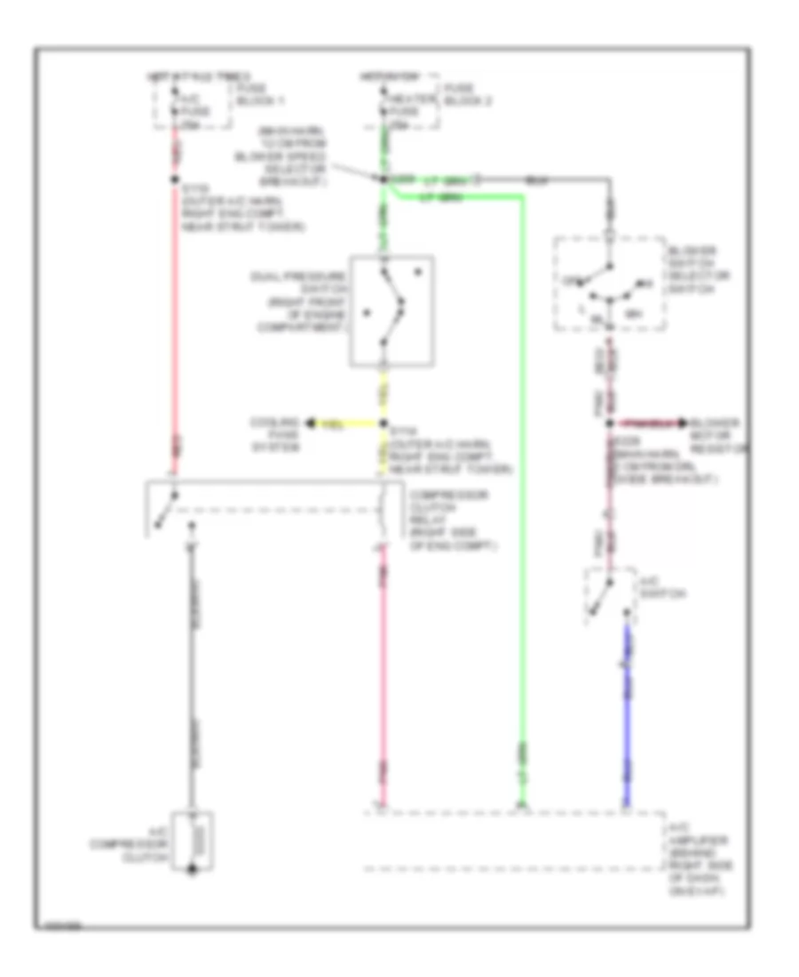
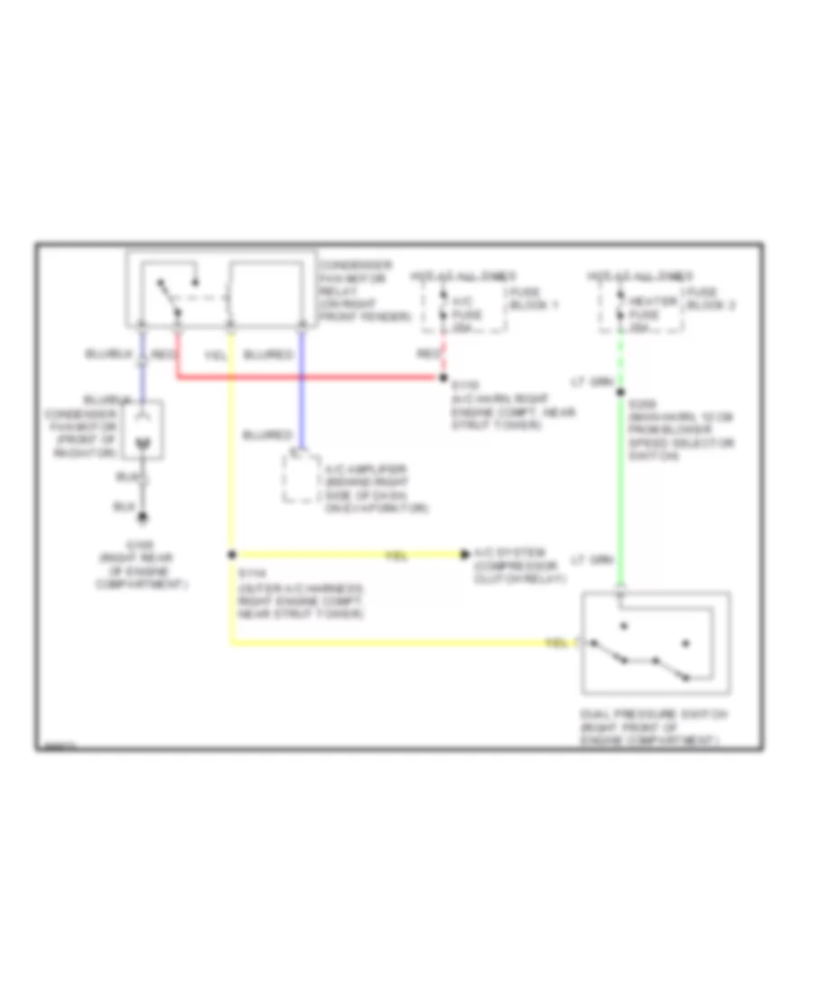
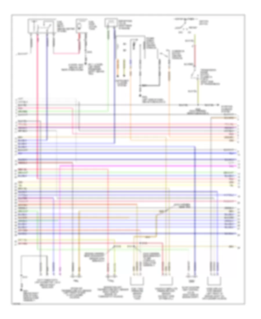
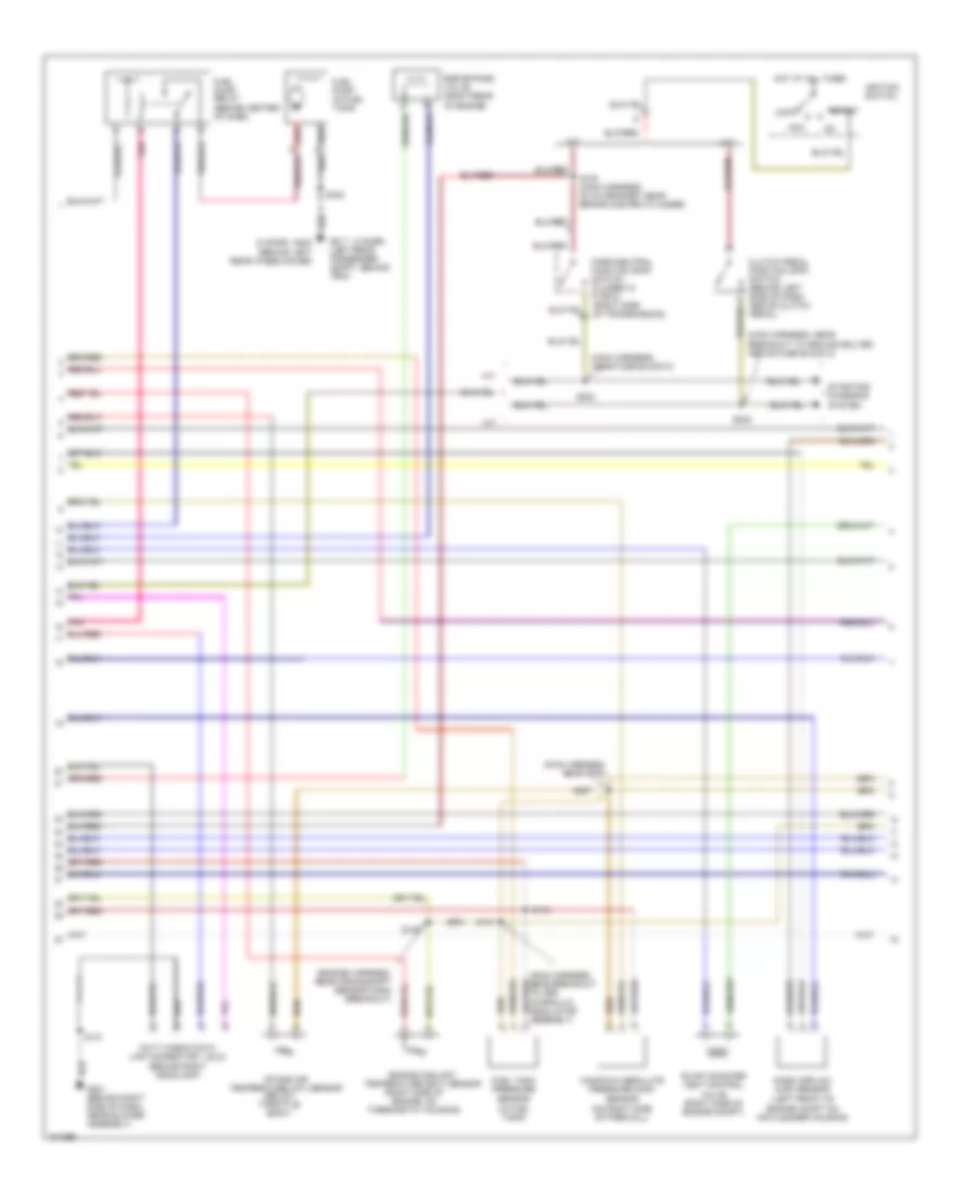
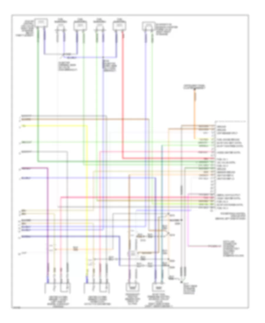
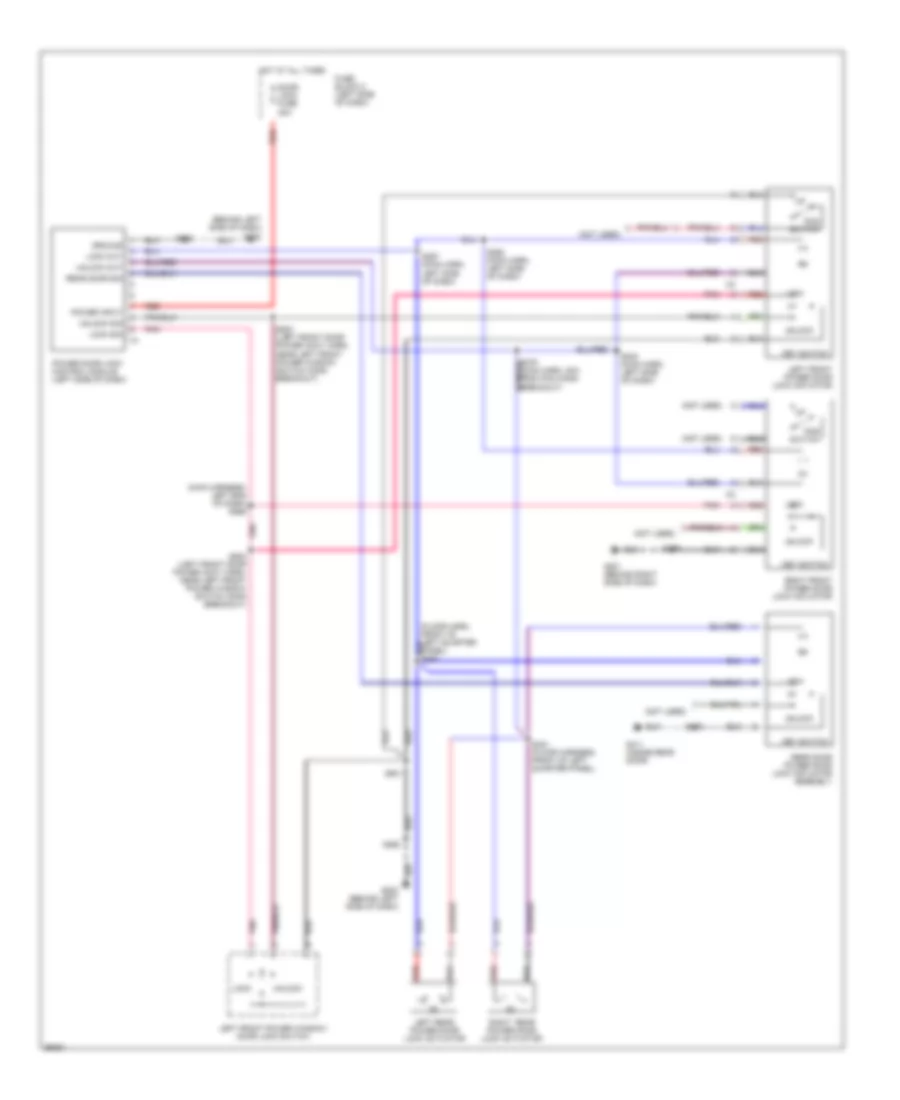
AIR CONDITIONING
A/C Wiring Diagram for Chevrolet Tracker 1998
 https://portal-diagnostov.com/license.html
Automotive Electricians Portal FZCO
Automotive Electricians Portal FZCO
https://portal-diagnostov.com/license.html
https://portal-diagnostov.com/license.html
Automotive Electricians Portal FZCO
Automotive Electricians Portal FZCO
List of elements for A/C Wiring Diagram for Chevrolet Tracker 1998:
- (3-speed a/t, m/t)
- (4-speed a/t)
- (behind right side of dash)
- (left side of dash) powertrain control module
- (main harness, 12 cm from blower speed selector breakout)
- (on evaporator)
- (outer a/c harness, right engine compt, near strut tower)
- A/c compressor clutch
- A/c amplifier (behind right side of dash, on evaporator)
- A/c fuse 25a
- A/c switch
- Blower motor (right side of dash)
- Blower motor resistor (right side of dash)
- Blower speed selector switch
- Blower switch
- C 1995 vftc
- Compressor clutch relay (right side of engine compt)
- Condenser fan motor (front of radiator)
- Condenser fan motor relay (right side of engine compt)
- Coolant temperature switch (on intake manifold)
- Dual pressure switch (right front of engine compartment)
- Fuse block 1
- Fuse block 2
- G105 (right rear of engine compartment)
- G201
- G201 (behind right side of dash)
- Heater fuse 25a
- Hot at all times
- Hot in on
- Off
- Pnk
- Red
- S110
- S114
- S209
- S228 (main harness, behind right side of dash)
- S239 (main harness, 2cm from daytime running lights diode breakout)
- S259 (a/c jumper harness, near a/c amplifier)
- Starting/ charging system
- Thermistor
Compressor Wiring Diagram for Chevrolet Tracker 1998
List of elements for Compressor Wiring Diagram for Chevrolet Tracker 1998:
- (main harn, 12 cm from blower speed selector breakout)
- A/c amplifier (behind right side of dash, on evap)
- A/c compressor clutch
- A/c fuse 25a
- A/c switch
- Blower motor resistor
- Blower switch selector switch
- Compressor clutch relay (right side of eng compt)
- Cooling fans system
- Dual pressure switch (right front of engine compartment)
- Fuse block 1
- Fuse block 2
- Heater fuse 25a
- Hot at all times
- Hot in on
- Off
- Pnk
- Red
- Right eng compt, near strut tower)
- S110 (outer a/c harn, right eng compt, near strut tower)
- S209
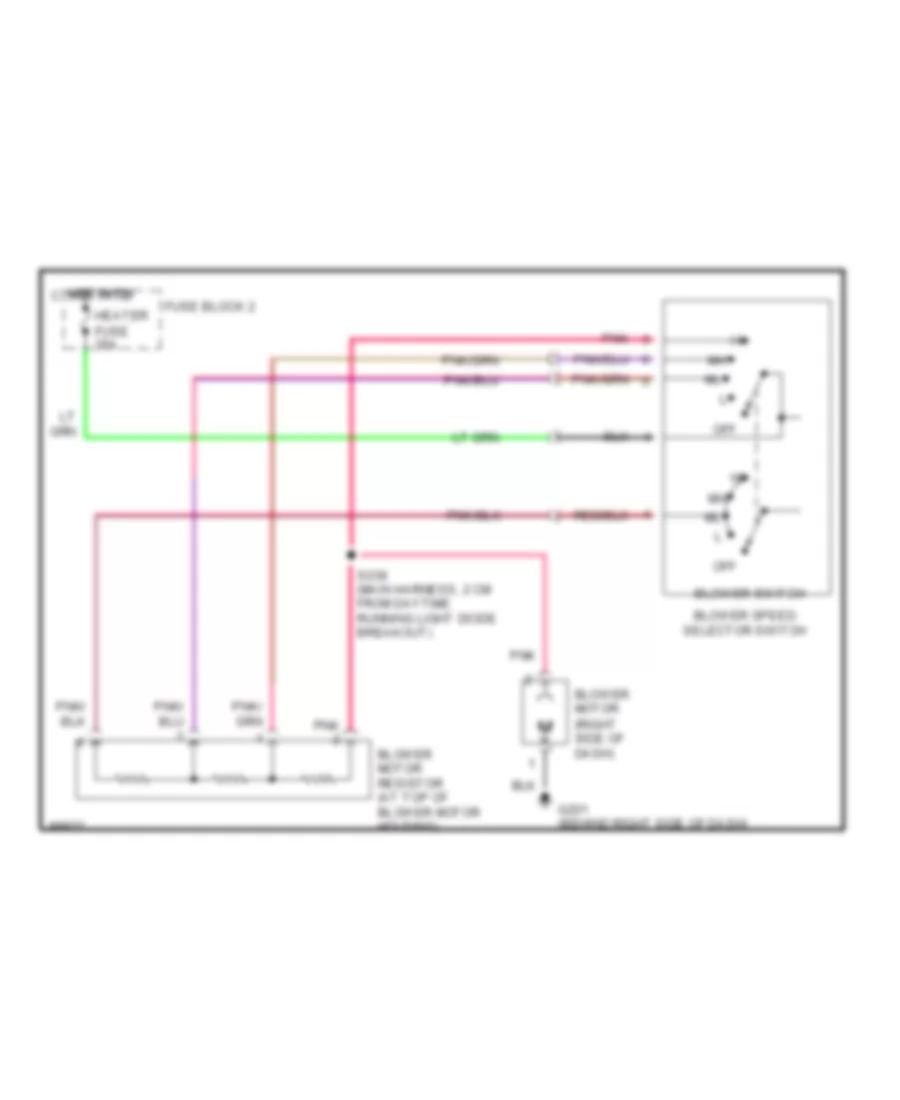
Heater Wiring Diagram for Chevrolet Tracker 1998
List of elements for Heater Wiring Diagram for Chevrolet Tracker 1998:
- Blower motor (right side of dash)
- Blower motor resistor (at top of blower motor housing)
- Blower speed selector switch
- Blower switch
- Fuse block 2
- G201 (behind right side of dash)
- Heater fuse 25a
- Hot in on 1995 vftc c
- Off
- Pnk
- S239 (main harness, 2 cm from daytime running light diode breakout)
ANTI-LOCK BRAKES
Anti-lock Brake Wiring Diagrams for Chevrolet Tracker 1998
List of elements for Anti-lock Brake Wiring Diagrams for Chevrolet Tracker 1998:
- "4wd" ind
- (i/p harn, near left front speaker) s211
- (left kick panel) g200
- (main harn, near abs control module)
- (main harn, right side of dash)
- 4 speed a/t
- 4wd switch
- Abs active ind
- Abs fuse 50a
- Abs ind
- Abs motor pack assembly (left rear of engine compt)
- Abs resistor (right side of dash)
- Accelerometer (4wd only) (below front of center console)
- Brake ind
- Brake light switch
- C10
- C11
- C12
- C13
- C14
- C15
- C16
- D10
- D11
- D12
- D13
- D14
- D15
- D16
- Data link connector (obd-ii) (right of steering column)
- Diode 2 (behind dash, taped to harn)
- Electronic brake control module (right of steering column)
- Electronic brake control relay (left inner fender panel)
- Fuse box
- Fuse box 2
- G101 (right inner fender, near battery)
- G200 (left kick panel)
- Hot at all times
- Hot in on
- Hot in on or start
- Ig-coil meter fuse 15a
- Instrument cluster
- Lamp driver relay (left inner fender panel)
- Left front abs solenoid (attached to motor assembly)
- Left front speed sensor
- Lf motor
- M/t & 3 speed a/t
- Main fuse box
- Pnk
- Powertrain control module (left of steering column)
- Rear defg fuse 15a
- Rear motor
- Rear speed sensor
- Rf motor
- Right front speed sensor
- S108
- S132
- S208
- S209
- S213
- S251
- S260 (main harn, near blower switch)
- S270
- S271
- S272
- S275
- S278
- S280 (main harn, 3cm from pcm connectors breakout)
- S281 (main harness, left side of dash)
- S298
- Shuttle switch (left rear of engine compt)
- Stop horn fuse 15a
- Tail dome fuse 15a
- Turn back fuse 15a
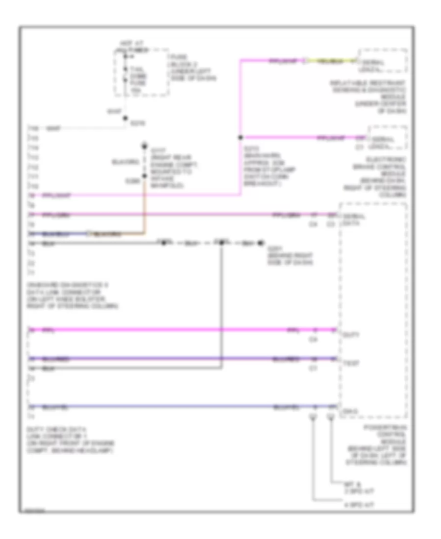
COMPUTER DATA LINES
Computer Data Lines for Chevrolet Tracker 1998
List of elements for Computer Data Lines for Chevrolet Tracker 1998:
- 4 spd a/t
- Diag
- Duty
- Duty check data link connector 1 (on right front of engine compt, behind headlamp)
- Electronic brake control module (behind dash, right of steering column)
- Fuse block 2 (under left side of dash)
- G117 (right rear engine compt, mounted to intake manifold)
- G201 (behind right side of dash)
- Hot at all times
- Inflatable restraint sensing & diagnostic module (under center of dash)
- M/t & 3 spd a/t
- On-board diagnostics ii data link connector (on left knee bolster, right of steering column)
- Powertrain control module (behind left side of dash, left of steering column)
- S213 (main harn, approx 3cm from stoplamp switch conn breakout)
- S216
- S220
- S286
- S297
- Serial data
- Tail dome fuse 15a
- Test
COOLING FAN
Cooling Fan Wiring Diagram for Chevrolet Tracker 1998
List of elements for Cooling Fan Wiring Diagram for Chevrolet Tracker 1998:
- (outer a/c harness, right engine compt, near strut tower)
- (right rear
- A/c amplifier (behind right side of dash, on evaporator)
- A/c fuse 25a
- A/c system (compressor clutch relay)
- Compartment)
- Condenser fan motor (front of radiator)
- Condenser fan motor relay (on right front fender)
- Dual pressure switch (right front of engine compartment)
- Fuse block 1
- Fuse block 2
- G105
- Heater fuse 25a
- Hot at all times
- Of engine
- Red
- S110 (a/c harn, right engine compt, near strut tower)
- S114
- S209 (main harn, 12 cm from blower speed selector switch)
CRUISE CONTROL
Cruise Control Wiring Diagram for Chevrolet Tracker 1998
List of elements for Cruise Control Wiring Diagram for Chevrolet Tracker 1998:
- (4-spd a/t)
- (except 4-spd a/t)
- (main harn, 4 cm from stop lamp switch breakout)
- (main harn, 5cm from steering column breakout)
- (main harn, 7 cm from blower switch breakout)
- (main harn, near breakout to pcm)
- 3-speed
- 4-spd a/t only
- 4-speed
- A/t
- All times
- And start
- Brake sig
- Cancel
- Cancel sig
- Clutch pedal position interrupt switch (on clutch pedal support)
- Cruise control actuator (right engine compt, near strut tower)
- Cruise control mode switch
- Cruise control on/off switch
- Cruise ind
- Engine controls system
- Fi fuse 15a
- Fuse block
- G202 (behind left side of dash)
- G206 (behind center of dash)
- G206 (center of dash)
- Ground
- Hot at
- Hot in on
- Ig coil meter fuse 15a
- Ignition
- Ind ctrl
- Instrument panel cluster assembly
- Interior lights system
- Interrupt
- M/t
- Main relay (behind glove box)
- Mode sig
- O/d cut
- On/off ind
- Park/ neutral position switch
- Powertrain control module (under left side of dash)
- Red
- Res/acc
- S100 (main harn, 21 cm from wiper motor breakout)
- S136 (engine harn, 1 cm from distributor breakout)
- S204
- S210
- S215
- S222
- S251
- S252
- S260
- S272
- S284
- S295
- S298
- Set/coast
- Starter solenoid
- Stop lamp switch (on brake pedal bracket)
- Stop/ horn fuse 15a
- Tp input
- Transmission range switch
- Vss
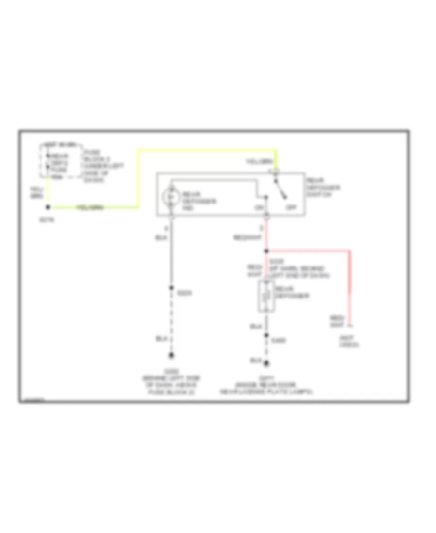
DEFOGGERS
Defogger Wiring Diagram for Chevrolet Tracker 1998
List of elements for Defogger Wiring Diagram for Chevrolet Tracker 1998:
- (not used)
- Fuse block 2 (under left side of dash)
- G202 (behind left side of dash, above fuse block 2)
- G411 (inside rear door, near license plate lamps)
- Hot in on
- Off
- Rear defg fuse 15a
- Rear defogger
- Rear defogger ind
- Rear defogger switch
- S226
- S235 (i/p harn, behind left end of dash)
- S278
- S400
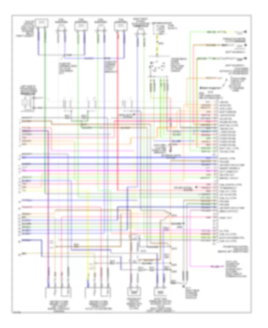
ENGINE PERFORMANCE
1.6L
1.6L (VIN 6), Engine Performance Wiring Diagrams, 4-Speed Transmission (1 of 3) for Chevrolet Tracker 1998
List of elements for 1.6L (VIN 6), Engine Performance Wiring Diagrams, 4-Speed Transmission (1 of 3) for Chevrolet Tracker 1998:
- "od/ off" ind
- "power" ind
- (engine harness, near starter motor breakout)
- (main harn, 18 cm from breakout to blower speed selector switch connector)
- (main harn, 7 cm from breakout to blower speed selector switch connector)
- (main harness, at left kick panel)
- (main harness, near grommet s139 at right side of firewall)
- A/c amplifier
- A/c on sig
- Abs idle-up sig
- Brake sig
- Camshaft position (cmp) sensor
- Cmp sig
- Cruise control system
- Cruise ctrl act sig
- Ctp sw sig
- Diagn request sig
- Distributor
- Ect in
- Egr bypass ctrl
- Egr solenoid vacuum valve (right front of engine)
- Electronic brake control module
- Evap can vent ctrl
- Evap tank press ctrl
- Fi fuse 15a
- Fuel gauge gnd
- Fuel level in
- Fuel tank press in
- Fuse block 1
- Fuse block 2
- G116 (on left side of bulkhead, near distributor)
- Ho2s 1 sig
- Ho2s 2 heater ctrl
- Ho2s 2 sig
- Hot at all times
- Hot in start or on
- Iat in
- Ig-coil meter fuse 15a
- Ign ref hi
- Ign ref lo
- Igniter
- Ignition coil
- Instrument cluster system (tachometer)
- Instrument panel cluster assembly
- J/c 2 (behind blower speed selector switch)
- Maf sig
- Main relay (behind glove box)
- Malfunction indicator lamp
- Map in
- Noise suppressor filter (below front wiper motor)
- Pnk
- Power steering pressure switch (in power steering pump)
- Power string press
- Powertrain control module (pcm) (behind left side of dash)
- Ref voltage
- S106
- S125
- S130
- S132
- S205
- S210
- S227
- S251
- S264
- S272
- S276
- S288 (main harness, 2 cm from breakout to ground bolted above fuse block 2)
- S294
- S295
- Sensor gnd
- Starter sig
- Stop horn fuse 15a
- Stoplamp switch (above brake pedal)
- Tail dome fuse 15a
- Test sw sig
- Throttle position (tp) sensor (on throttle body)
- To spark plugs
- Tp sensor sig
- Vss in
1.6L (VIN 6), Engine Performance Wiring Diagrams, 4-Speed Transmission (2 of 3) for Chevrolet Tracker 1998
List of elements for 1.6L (VIN 6), Engine Performance Wiring Diagrams, 4-Speed Transmission (2 of 3) for Chevrolet Tracker 1998:
- (2 door)
- (4 door)
- (engine harness, near crankshaft sensor conn breakout)
- (left front of eng, in air cleaner housing)
- (left front of engine compt on air cleaner housing)
- (main harness, near pcm)
- (main harness, near breakout to abs hydraulic modulator assembly)
- (right side of engine, on thermostat housing)
- Acc
- Duty check data link connector 1 (dlc) (behind right headlamp)
- Egr bypass valve (right rear of engine)
- Engine coolant temperature (ect) sensor
- Evap canister vent control valve (right side of engine compt)
- Fuel pump (in fuel tank)
- Fuel pump relay (behind center of dash)
- Fuel tank pressure
- G201 (behind right side of dash, near blower assembly)
- G202 (left side of dash, above fuse block 2)
- G317 (left rear passenger compt, behind trim)
- G402 (behind left rear wheelhouse)
- Hot at all times
- Ignition switch
- Instrument cluster system
- Intake air temperature (iat) sensor
- Lock
- Manifold absolute pressure (map)
- Mass airflow (maf) sensor
- Normal
- Overdrive switch (center console)
- Pnk
- Power
- Power/ normal switch (center console)
- Red
- S112
- S122
- S131
- S141
- S223 (main harness, near fuse block 2)
- S234
- S287
- S402
- Sensor (in fuel tank)
- Sensor (on right side of firewall)
- Start
- Starting/ charging system
- Transmission range switch (closed in p or n) (right side of transmission)
1.6L (VIN 6), Engine Performance Wiring Diagrams, 4-Speed Transmission (3 of 3) for Chevrolet Tracker 1998
List of elements for 1.6L (VIN 6), Engine Performance Wiring Diagrams, 4-Speed Transmission (3 of 3) for Chevrolet Tracker 1998:
- (injector harness, near iac valve conn break out)
- (injector harness, near inj 4 conn breakout)
- (left side of transmission) vehicle speed sensor (vss)
- (main harn, 6 cm from noise filter breakout)
- (right front of eng) evap canister purge valve
- 2 position sig
- 4wd lo sig
- Crankshaft position sensor (ckp) (front of oil pan)
- Cruise control system
- D position sig
- Data link connector on board diagnostics ii (dlc-odbii) (right side of steering column)
- Duty check out
- Egr sol vac out
- Evap can purge ctrl
- Evap tank pressure control solenoid vacuum valve (right side of eng compt, near fuse box 1)
- Exterior lights system
- Four speed automatic transmission (in transmission)
- Four wheel drive low switch (top of transfer case)
- Fuel inj 1 ctrl
- Fuel inj 2 ctrl
- Fuel inj 3 ctrl
- Fuel inj 4 ctrl
- Fuel injector 1
- Fuel injector 2
- Fuel injector 3
- Fuel injector 4
- Fuel pump rly ctrl
- Fuse block 2
- G117 (right rear of engine, on intake manifold)
- G202 (left side of dash, above fuse block 2)
- Headlights system
- Heated oxygen sensor 1 (ho2s1) (left side of engine, in exhaust manifold)
- Heated oxygen sensor 2 (ho2s2) (after 3-way catalytic converter)
- Ho2s 1 out
- Hot in on & start
- Iac valve ctrl
- Idle air control (iac) valve (right side of engine, below throttle body)
- Ign ctrl out
- Ign positive voltage
- L position sig
- Lights on sig
- Main rly ctrl
- Memory power in
- Mil ctrl
- N position sig
- O/d off ind
- Od sw sig
- Pcm gnd
- Pnk
- Power ind ctrl
- Powertrain control module (pcm) (behind left side of dash)
- R position sig
- Red
- S107
- S108
- S128
- S129
- S133
- S140
- S208
- S218
- S219
- S285
- S286
- S299
- Serial data out
- Shif t sol 1 ctrl
- Shift mode sig
- Shift sol 2 ctrl
- Shift solenoid 1
- Shift solenoid 2
- Tcc sol ctrl
- Torque converter clutch solenoid
- Tp sensor out
- Transmission range switch (right side of trans- mission)
- Turn back fuse 15a
- Vss sig
- Vss sig low
1.6L (VIN 6), Engine Performance Wiring Diagrams, Manual & 3-Speed Transmission (1 of 3) for Chevrolet Tracker 1998
List of elements for 1.6L (VIN 6), Engine Performance Wiring Diagrams, Manual & 3-Speed Transmission (1 of 3) for Chevrolet Tracker 1998:
- (engine harness, near starter motor breakout)
- (main harn, 18 cm from breakout to blower speed selector switch connector)
- (main harn, 7 cm from breakout to blower speed selector switch connector)
- (main harn, 8 cm from grommet at left side of firewall)
- (main harn, at left kick panel) s294
- (main harn, near grommet at right side of firewall)
- A/c amplifier
- A/c on signal
- Camshaft position (cmp) sensor
- Crank signal
- Diag request signal
- Distributor
- Duty check output
- Ect sensor input
- Ect sig or tcc relay
- Egc in ho2s1
- Egc in hos2s
- Egr bypass valve
- Egr sol vac valve in
- Egr solenoid vacuum valve (right front of engine)
- Electronic brake control module (ebmc)
- Fi fuse 15a
- Fuel level sens sig
- Fuel pump rel cntrl
- Fuel tank press in
- Fuse block 1
- Fuse block 2
- G116 (on left side of bulkhead, near distributor)
- Hot at all times
- Hot in start or on
- Iat sensor input
- Idle switch signal
- Idle-up sig (abs)
- Ig-coil meter fuse 15a
- Igniter
- Igniter driver output
- Ignition coil
- Ignition power input
- Instrument cluster (tach- ometer)
- Instrument cluster system
- Instrument panel cluster assembly
- Maf sensor input
- Main relay (behind glove box)
- Main relay control
- Malfunction indicator lamp
- Map sensor input
- Memory power input
- Mil indic control
- Noise suppressor filter (below front wiper motor)
- P/n signal
- Pnk
- Power steering pressure switch (in power steering pump)
- Powertrain control module (pcm) (behind left side of dash)
- Pwr steering pres
- Ref voltage
- S106
- S125
- S130
- S132
- S139
- S142
- S204
- S210
- S227
- S264
- S272
- S276
- S295
- Tail dome fuse 15a
- Test switch signal
- Three speed automatic transmission
- Throttle position (tp) sensor (on throttle body)
- To spark plugs
- Torque converter clutch relay (front of battery)
- Torque converter clutch solenoid
- Tp input
- Vehicle speed input
1.6L (VIN 6), Engine Performance Wiring Diagrams, Manual & 3-Speed Transmission (2 of 3) for Chevrolet Tracker 1998
List of elements for 1.6L (VIN 6), Engine Performance Wiring Diagrams, Manual & 3-Speed Transmission (2 of 3) for Chevrolet Tracker 1998:
- (2 door)
- (4 door)
- (below throttle body)
- (engine harness, near crankshaft sensor conn breakout)
- (left front of engine compt on air cleaner housing)
- (main harness, near pcm)
- (main harness, near breakout to abs hydraulic modulator assembly)
- (main harness, near breakout to ground bolted above fuse block 2)
- (main harness, near fuse block 2)
- (right side of engine, on thermostat housing)
- A/t
- Acc
- Clutch pedal position (cpp) switch (behind left side of dash, above clutch pedal)
- Duty check data link connector 1 (dlc) (behind right headlamp)
- Egr bypass valve (right rear of engine)
- Engine coolant temperature (ect) sensor
- Evap canister vent control valve (right side of engine compt)
- Fuel pump (in fuel tank)
- Fuel pump relay (behind center of dash)
- Fuel tank pressure
- G201 (behind right side of dash, near blower assembly)
- G317 (left rear passenger compt, behind trim)
- G402 (behind left rear wheelhouse)
- Hot at all times
- Ignition switch
- Intake air temperature (iat) sensor
- Lock
- M/t
- Manifold absolute pressure (map)
- Mass airflow (maf) sensor
- Park/neutral position (pnp) switch (closed in p or n) (right side of transmission)
- Pnk
- Red
- S100 (main harness, 20 cm grommet near brake master cylinder)
- S112
- S122
- S131
- S141
- S223
- S248
- S287
- S402
- Sensor (in fuel tank)
- Sensor (on right side of firewall)
- Start
- Starting/ charging system
1.6L (VIN 6), Engine Performance Wiring Diagrams, Manual & 3-Speed Transmission (3 of 3) for Chevrolet Tracker 1998
List of elements for 1.6L (VIN 6), Engine Performance Wiring Diagrams, Manual & 3-Speed Transmission (3 of 3) for Chevrolet Tracker 1998:
- (injector harness, near iac valve conn breakout)
- Cmp sensor input
- Crankshaft position sensor (ckp) (front of oil pan)
- Data link connector on board diagnostics ii (dlc-odbii) (right of steering column)
- Evap can purge cntrl
- Evap can vent cntrl
- Evap tank pres cntrl
- Evap tank pressure control solenoid vacuum valve (right side of eng compt, near fuse box 1)
- Evaporative emission canister purge valve (right front of engine)
- Fuel gauge ground
- Fuel inj 1
- Fuel inj 2
- Fuel inj 3
- Fuel inj 4
- Fuel injector 1
- Fuel injector 2
- Fuel injector 3
- Fuel injector 4
- G117 (right rear of engine, on intake manifold)
- Ground
- Heated oxygen sensor 1 (ho2s1) (left side of engine, in exhaust manifold)
- Heated oxygen sensor 2 (ho2s2) (after 3-way catalytic converter)
- Ho2s1 heater cntrl
- Ho2s2 heater cntrl
- Iac valve cntrl
- Idle air control (iac) valve (right side of engine, below throttle body)
- Ignition ref hi
- Ignition ref lo
- Instrument panel cluster assembly
- Pnk
- Powertrain control module (pcm) (behind left side of dash)
- Red
- S129
- S133
- S218
- S219
- S285
- S286
- S299
- Sensor ground
- Serial data output
EXTERIOR LIGHTS
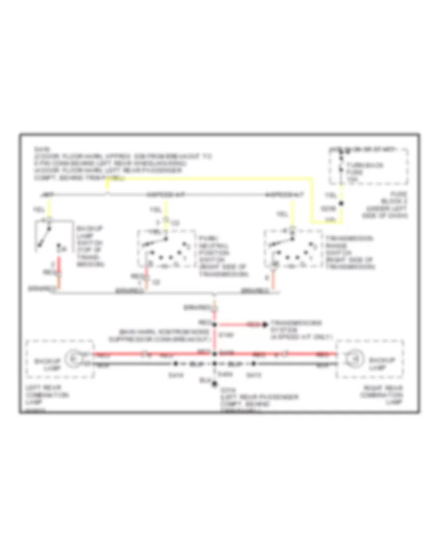
Backup Lamps Wiring Diagram for Chevrolet Tracker 1998
List of elements for Backup Lamps Wiring Diagram for Chevrolet Tracker 1998:
- (main harn, 6cm from noise suppressor conn breakout)
- 3-speed a/t
- 4-speed a/t
- Backup lamp
- Backup lamp switch (top of trans- mission)
- Fuse block 2 (under left side of dash)
- G314 (left rear passenger compt, behind trim panel)
- Hot in on or start
- Left rear combination lamp
- M/t
- Park/ neutral position switch (right side of transmission)
- Red
- Right rear combination lamp
- S140
- S208
- S404
- S414
- S415
- S418
- S418: (2 door: floor harn, approx 3cm from breakout to 6 pin conn behind left rear wheelhousing) (4 door: floor harn, left rear passenger compt, behind trim panel)
- Transmission range switch (right side of transmission)
- Transmissions system (4 speed a/t only)
- Turn back fuse 15a
Exterior Lamps Wiring Diagram for Chevrolet Tracker 1998
List of elements for Exterior Lamps Wiring Diagram for Chevrolet Tracker 1998:
- (2 door)
- (behind glove box) headlamp relay 2
- (behind left rear wheelhousing)
- (behind left side of dash)
- (behind right dash, near blower assembly)
- (floor harn, approx 5cm from break out to 6-pin conn behind left rear wheelhousing-2dr)
- (floor harn, approx 5cm from left kick panel grommet-2 door)
- (floor harn, left rear passenger compt, behind trim pnl-4 door)
- (floor harn, left rear passenger compt, behind trim pnl-4 door) s411 (floor harn, approx 2cm from break out to 6-pin conn behind left rear wheelhousing- 2 door)
- (floor harn, left rear passenger compt, behind trim pnl-4 door) s413 (floor harn, approx 10cm from break out to 6-pin conn behind left rear wheelhousing)
- (i/p harn, approx 2 to 3cm from power mirror switch conn break out)
- (inside rear door near license plate lamps)
- (main harn, 8cm from drl control module connector breakout)
- (main harn, approx 16cm from ignition switch conn break out)
- (main harn, approx 1cm from blower speed selector switch conn break out)
- (main harn, approx 1cm from stoplamp switch conn break out)
- (not used)
- (rear door harn, near license plate lamps) s410*/s407**
- (rear lamp harn, near right rear combination lamp) s416
- Center high mount stoplamp
- Combination switch
- Fuse block 2 (under left side of dash)
- G100 (left front inner fender)
- G101 (near washer fluid reservoir)
- G201
- G201 (behind right side of dash)
- G202
- G314 (left rear passenger compt, behind trim panel)
- G402
- G411
- Hazard fuse 15a
- Hazard switch
- Head
- Headlight/ dimmer switch
- Hot at all times
- Hot in on or start
- Instrument panel cluster assembly
- Left front park/ turn lamp
- Left front side marker lamp
- Left license plate lamp
- Left rear combination lamp
- Left rear side marker lamp
- Left turn indicator
- Off
- Park
- Right front park/ turn lamp
- Right front side marker lamp
- Right license plate lamp
- Right rear combination lamp
- Right rear side marker lamp
- Right turn indicator
- S103
- S120
- S208
- S212
- S214
- S220
- S221
- S231
- S232 (main harn, behind left side of dash)
- S250
- S251
- S255
- S257
- S258
- S260 (main harn, approx 4cm from stoplamp switch conn break out)
- S283
- S400
- S401
- S403
- S404
- S408 (rear lamp harn, near left rear combination lamp)
- S409
- S414
- S415
- S417 (floor harn, near left rear wheelhouse)
- S424* s412**
- Splices: * 2-door ** 4-door
- Stop horn fuse 15a
- Stoplamp switch (above brake pedal)
- Tail dome fuse 15a
- Tail/ stop- lamp
- Trailer connector (behind left rear wheel housing)
- Turn back fuse 15a
- Turn lamp
- Turn signal switch
- Turn/hazard relay (center of dash, below blower switch)
GROUND DISTRIBUTION
Ground Distribution Wiring Diagram (1 of 3) for Chevrolet Tracker 1998
List of elements for Ground Distribution Wiring Diagram (1 of 3) for Chevrolet Tracker 1998:
- (not used)
- A/c condenser fan
- A/t
- Battery
- Braid
- Brake fluid level switch
- Crankshaft position sensor shield
- Data link connector on board diagnostics ii
- Distributor
- Electronic brake control module
- Front washer pump
- Front wiper motor
- G100 (left front inner fender)
- G101 (right front inner fender, near washer fluid reservoir)
- G101 (right inner fender, near battery)
- G105 (right inner fender, near battery)
- G116 (left bulkhead near front wiper motor)
- G117 (right rear engine compartment mounted to intake manifold)
- G117 (right rear engine, near distributor)
- G120 (right engine near starter
- G123 (on bulkhead behind distributor)
- G206 (center of dash, on sensing and diagnostic module mounting bracket)
- Heated oxygen sensor 1 shield
- Heated oxygen sensor 2 shield
- Horn
- Inflatable restraint i/p module
- Left front side marker lamp
- Left front abs solenoid
- Left front park/ turn lamp
- M/t & 3 speed a/t
- Mass air flow sensor
- Motor)
- Noise supressor filter
- Powertrain control module
- Rear washer pump
- Right front park/ turn lamp
- Right front side marker lamp
- Right horn
- S103 (main harness, near right horn connector breakout)
- S104 (main harness, near front washer pump connector breakout)
- S106 (main harness, near g102 breakout)
- S107 (engine harness, under intake manifold)
- S120 (main harness, behind left headlamp)
- S133 (main harness, near brake master cylinder)
- S218 (main harness, left end of dash)
- S219 (main harn, 10cm from drl control module connector breakout)
- S270 (main harn, near electronic brake control module breakout)
- S285 (main harn, 10cm from drl control module conn breakout)
- S286 (main harness, left side of dash)
- S299 (main harn, near grommet, left side
- Sensing and diagnostic module
- Shuttle switch
- Vehicle speed sensor shield
Ground Distribution Wiring Diagram (2 of 3) for Chevrolet Tracker 1998
List of elements for Ground Distribution Wiring Diagram (2 of 3) for Chevrolet Tracker 1998:
- (a/c jumper harn, right side of dash) s259
- (i/p harness, left side of dash)
- (main harn, center of dash) s222
- (not used)
- A/c amplifier
- A/c switch
- Audio alarm module
- Blower motor
- C208
- Capacitor
- Cigar lighter
- Combination switch
- Cpp interrupt switch
- Cruise control actuator
- Cruise control mode switch
- Data link connector (obd ii)
- Data link connector 1 (duty check)
- Daytime running lamps control module
- Four wheel drive low switch module
- Four wheel drive switch
- G201 (behind right side of dash)
- G202 (behind left side of dash)
- G206 (center of dash)
- Headlamp relay 1
- Ignition switch
- Illumination controller
- Instrument panel cluster assembly
- Lamp driver relay
- Left front power door lock actuator assembly
- Left front power window/ door lock switch
- Overdrive switch
- Pnp switch (3 spd a/t)
- Power door lock control module
- Power mirror switch
- Power normal switch
- Radio
- Rear defogger switch
- Right front power door lock actuator assembly
- S108 (trans harn, near 4wd switch breakout)
- S131 (main harn, right rear of engine compartment)
- S135 (engine harness, rear of engine compartment)
- S214 (main harn, left side of dash)
- S220 (main harn, 1cm from blower speed selector switch conn breakout)
- S226
- S229 (main harn, 7cm from ignition switch connector breakout)
- S230 (main harness, left rear of vehicle)
- S234 (in manual selector lever harness)
- S262 (main harn, 8cm from stoplamp conn breakout)
- S284 (main harn, left side of dash)
- S296 (main harn, 6cm from stoplamp conn breakout)
- S297 (main harn, 5cm from drl diode conn breakout)
- S298 (main harn, left side of dash)
- S501 (left front door power accy harness, inside left front door harness)
- Shift lock relay
- Shift lock solenoid
- Turn/ hazard relay
Ground Distribution Wiring Diagram (3 of 3) for Chevrolet Tracker 1998
List of elements for Ground Distribution Wiring Diagram (3 of 3) for Chevrolet Tracker 1998:
- (floor harn, 20cm from left rear speaker conn breakout) s306
- 2 door
- 4 door
- Backup lamp
- C407
- Center high mount stop lamp
- Fuel level sensor
- Fuel pump
- G314 (left rear passenger compartment, behind trim panel)
- G402 (rear lamp harness, behind left rear wheelhousing
- G407
- G407 (rear door harness, near rear wiper motor)
- G411 (inside rear door near license plate lamps)
- Left door jamb switch
- Left front door jamb switch
- Left license plate lamp
- Left rear combination lamp
- Left rear door jamb switch
- Left rear side marker
- Rear defogger
- Rear door jamb switch
- Rear door power door lock actuator assembly
- Rear wiper motor
- Right door jamb switch
- Right front door jamb switch
- Right license plate lamp
- Right rear combination lamp
- Right rear door jamb switch
- Right rear side marker
- S301 (sub-floor harness, near seat belt switch connector breakout)
- S400 (rear door harness, near g400 breakout)
- S400 (rear door harness, near g411 breakout)
- S401 (rear lamp harness, near left rear comb lamp)
- S402 (rear lamp harness, near right rear comb lamp)
- S402 (rear lamp harness, near right rear combination lamp)
- S403 (rear lamp harness, near right rear comb lamp)
- S404 (floor harness, behind left wheel housing)
- S404 (floor harness, near left rear speaker connector breakout)
- S405 (rear door harness, near g300 breakout)
- S406 (floor harness, near g300 breakout)
- S414 (left rear comb lamp jumper, near left rear comb lamp)
- S415 (right rear comb lamp jumper, near right rear comb lamp)
- S426 (floor harn, left rear of vehicle)
- Seat belt switch
- Tail/ stop lamp
- To trailer connector harness
- Turn lamp
HEADLIGHTS
Headlight Wiring Diagram for Chevrolet Tracker 1998
List of elements for Headlight Wiring Diagram for Chevrolet Tracker 1998:
- (behind left side of dash) g202
- (behind right side of dash) g201
- (main harness, approximately 14 cm from left bulkhead branch breakout) s116
- (main harness, approximately 25 cm from ignition switch connector breakout)
- (main harness, near breakout to 6 cavity in-line conn, behind upper left side of dash) s281
- (on bulkhead behind distributor) g123
- Anti-lock brakes system
- Brake fluid level switch (on top of brake fluid reservoir)
- Brake ind ctrl
- Brake indicator
- Charge indicator
- Charge input
- Combination switch
- Daytime running lamps (drl) control module (behind dash, left of steering column)
- Daytime running lamps (drl) diode (on right side of dash, taped to harness above blower motor)
- Drl control
- Drl ind ctrl
- Drl indicator
- Fuse block no 1 (on right side of engine compartment, front of battery)
- Fuse block no 2 (under left side of dash)
- G206 (center of dash)
- Generator
- Ground
- Head
- Headlamp fuse 15a
- Headlamp relay no 1 (behind glove box)
- Headlamp/dimmer switch
- Headlamps on
- High beam indicator
- Hot at all times
- Hot in on or start
- Ig-coil meter fuse 15a
- Ignition
- Instrument panel cluster assembly
- Left
- Left headlamp
- Off
- Park
- Park brk sig
- Parking brake switch (on base of park brake lever)
- Pass
- Red
- Right headlamp
- Right headlamp fuse 15a
- S106
- S115
- S204
- S214
- S227
- S229
- S230
- S241 (main harness, approximately 2 cm from powertrain control module (pcm) connectors breakout)
- S243 (main harness, approx 4 cm from ground g202 breakout, behind left side of dash above fuse block no 2)
- S244
- S246 (main harness, approximately 14 cm from ignition switch connector breakout)
- S247
- S272
- S296
HORN
Horn Wiring Diagram for Chevrolet Tracker 1998
List of elements for Horn Wiring Diagram for Chevrolet Tracker 1998:
- (steering wheel assembly)
- Fuse block 2 (under left side of dash)
- G101 (right front inner fender, near washer fluid reservoir)
- Horn
- Horn relay (on center of dash, behind blower speed selector switch)
- Hot at all times
- Left horn switch
- Right horn conn (not used)
- Right horn switch
- S103
- S104
- S105 (main harn, 11cm from right headlamp conn breakout)
- S203
- Stop horn fuse 15a
INSTRUMENT CLUSTER
Instrument Cluster Wiring Diagram for Chevrolet Tracker 1998
List of elements for Instrument Cluster Wiring Diagram for Chevrolet Tracker 1998:
- ((2 door) floor harness, 20cm from left rear speaker conn breakout) ((4 door) floor harn, left rear quarter panel trim)
- (behind left side of dash)
- (on right side of engine compt, near strut tower) cruise control actuator
- 4 speed a/t
- 4wd ind
- A10
- A11
- A12
- A13
- A14
- A15
- A16
- A16 c1
- Abs active ind
- Abs ind
- Accy
- Air bag ind
- Anti-lock brakes system
- B10
- B10 c2
- Brake fluid level switch (on top of brake fluid reservoir)
- Brake ind
- Bulb test
- C10
- C11
- C12
- C13
- C13 c3
- Charge ind
- Cruise control system
- Cruise ind
- Daytime running lamps (drl) control module (behind dash, left of steering column)
- Diode no 2 (taped to harness, behind glove box)
- Drl ind
- Engine controls system
- Engine coolant temperature gauge
- Engine coolant temperature sending unit (at right side of engine, at thermostat housing)
- Exterior lights system
- Fuel gauge
- Fuel level sensor (in fuel tank)
- Fuel lvl sig
- Fuse block 2 (under left side of dash)
- G123 (on bulkhead, behind distributor)
- G202
- G206 (center of dash)
- G314 (left rear passenger compt, behind trim panel)
- Ground
- Headlights system
- High beam ind
- Hot in on and start
- Ig coil meter fuse 15a
- Ignition switch
- Illumination (3 bulbs)
- Ind ctrl
- Instrument panel cluster assembly
- Interior lights system (instrument illumination)
- Left turn ind
- Lock
- M/t and 3 speed a/t
- Mil ind
- O/d off ind
- Off
- Oil pressure ind
- Oil pressure switch (side of engine block, above oil filter)
- Parking brake switch (on base of park brake lever)
- Pnk
- Power ind
- Powertrain control module (behind left side of dash)
- Red
- Right turn ind
- S106
- S204
- S215 (main harness, near engine control module c2 breakout)
- S226
- S229
- S272
- S281 (main harn, behind left side of dash)
- S305 s419
- S402
- Seat belt ind
- Signal
- Start
- Starting/charging system
- Tachometer
- Transmission system
- Transmissions system
- Vehicle speed sensor
- Vss input
- Vss sig
- Warning system
INTERIOR LIGHTS
Interior Light Wiring Diagram for Chevrolet Tracker 1998
List of elements for Interior Light Wiring Diagram for Chevrolet Tracker 1998:
- (2 door: floor harn, 5 cm from left rear speaker conn breakout)
- (3- bulbs)
- (4 door: floor harn, approx 7 cm from g314 breakout)
- (behind left rear trim panel)
- (floor harn, approx 10 cm from left rear speaker conn breakout)
- 2-door
- 4-door
- Ashtray lamp
- Audio alarm module (behind right side of dash near front speaker)
- Bulbs
- Cigar lighter lamp
- Combination switch
- Cruise control on/off switch (w/ cruise control)
- Dome lamp
- Dome lamp diode
- Door
- Door open sig
- Exterior lights system
- Fuse block 2 (under left side of dash)
- G201 (behind right side of dash)
- G202 (behind left (side of dash)
- G314 (left rear passenger compt, behind trim panel)
- Ground
- Head
- Headlamp relay 2 (behind glove box)
- Headlamp/ dimmer switch
- Heater control illumination lamp
- Hot at all times
- Illumination controller
- Instrument panel cluster assembly
- Left door jamb switch
- Left front door jamb switch
- Left rear door jamb switch
- Lights on sig
- Manual selector lever illumination lamp (w/ a/t)
- Off
- Power
- Power/ normal switch (w/ 4-speed a/t only)
- Radio
- Rear defogger switch (4-door)
- Rear door jamb switch
- Rear wiper/ washer switch (4-door)
- Right door jamb switch
- Right front door jamb switch
- Right rear door jamb switch
- S201
- S212
- S214
- S221 (i/p harn, near fuse block 2)
- S226
- S231
- S250
- S263
- S265
- S276
- S282
- S300
- S301
- S304 (floor harn, approx 5 cm from left rear speaker conn breakout)
- S404
- S422 (4-door) s304 (2-door)
- S423 (floor harness, approx 8 cm from g314 breakout)
- S426
- Solid state
- Tail
- Tail dome fuse 15a
POWER DISTRIBUTION
Power Distribution Wiring Diagram (1 of 2) for Chevrolet Tracker 1998
List of elements for Power Distribution Wiring Diagram (1 of 2) for Chevrolet Tracker 1998:
- (i/p harness, 12cm from cigar lighter)
- (left side of dash)
- (main harness, approx 10cm from evap canister vent control valve) s115
- (main harness, approx 12cm from blower speed selector switch connector breakout) s209
- (main harness, approx 14cm from ground breakout at left dash) s278
- (main harness, approx 14cm from left bulkhead branch breakout) s116
- (main harness, approx 18cm from ignition switch breakout) s208
- (outer a/c harness, right engine compt, near strut tower) s110
- 3-spd a/t
- 4-spd a/t
- A/c amplifier
- A/c compressor clutch relay
- A/c condenser fan relay
- A/c fuse 25a
- Abs fuse 50a
- Acc
- Antilock brake system resistor
- Backup lamp switch
- Bat
- Batt fuse 80a
- Battery
- Blower speed selector switch
- C2 red
- Cigar lighter
- Cigar radio fuse 20a
- Combination switch
- Daytime running lamps diode
- Dual pressure switch
- Electronic brake control module
- Electronic brake control relay
- Fi fuse 15a
- Front wiper motor
- Fuse block 1 (right rear of engine compt, in front of battery)
- Fuse block 2 (left side of dash)
- G202
- Generator
- Heater fuse 25a
- Ig fuse 60a
- Ignition switch
- Instrument panel cluster assembly
- Lamp fuse 30a
- Left headlamp
- Left headlamp fuse 15a
- Lock
- M/t
- Main relay
- Park/ neutral position switch
- Power mirror switch
- Radio
- Rear defg fuse 15a
- Rear defogger switch
- Rear wiper motor
- Rear wiper/ washer switch
- Red
- Right headlamp
- Right headlamp fuse 15a
- Run
- S206 (main harn, approx 20cm from ignition switch connector breakout)
- S236 (i/p harness, approx 3cm from junction connector 2 breakout)
- S240 (main harness, approx 8cm from stoplamp switch connector breakout)
- S247 (main harn, right side of dash)
- Shift lock relay
- Start
- Starter solenoid
- Starting/ charging system
- To airbag fuse box (diagram 2 of 2)
- To fuse block 2 power windows circuit breaker (diagram 2 of 2)
- To fuse block 2 stop horn fuse (diagram 2 of 2)
- To ig coil meter fuse (diagram 2 of 2)
- Transmission range switch
- Turn back fuse 15a
- Wiper washer fuse 15a
Power Distribution Wiring Diagram (2 of 2) for Chevrolet Tracker 1998
List of elements for Power Distribution Wiring Diagram (2 of 2) for Chevrolet Tracker 1998:
- (i/p harn, left side of dash) s204
- (main harn, 20cm from noise filter conn breakout) s130
- (main harness, 11cm from ignition switch connector breakout) s275
- (main harness, 2cm from blower motor resistor connector breakout) s203
- (main harness, approx 10cm from ground break- out at left dash) s254
- (main harness, approx 11cm from ground breakout at left dash) s272
- (main harness, approx 12cm from stoplamp switch connector breakout) s210
- (main harness, approx 15cm from ground breakout at left dash) s202
- (main harness, approx 1cm from ground breakout at left dash) s276
- (main harness, approx 2cm from stoplamp switch connector breakout) s216
- (main harness, approx 5cm from blower motor resistor connector breakout) s250
- (main harness, approx 5cm from stop lamp switch connector breakout) s251
- (main harness, approx 7cm from noise suppressor filter connector breakout) s132
- (main harness, approx 8cm from stoplamp switch connector breakout) s227
- (not used) spotlamp
- 2 door
- 4 door
- 4 speed a/t
- Airbag fuse box (left side of dash)
- Audio alarm module
- C407
- Combination switch
- Cruise control on/off switch
- Data link connector on board diagnostics ii
- Daytime running lamps control module
- Distributor
- Dome lamp
- Door lock fuse 20a
- Electronic brake control module
- From fuse block 1 lamp fuse (diagram 1 of 2)
- From ignition switch (diagram 1 of 2)
- From turn back fuse (diagram 1 of 2)
- Fuel pump relay
- Fuse block 2 (left side of dash)
- Generator
- Hazard fuse 15a
- Headlamp relay 2
- Heated oxygen sensor 1
- Heated oxygen sensor 2
- Horn relay
- Ig coil meter fuse 15a
- Ignition key warning switch
- Inflatable restraint sensing and diagnostic module
- Instrument panel cluster assembly
- Lamp driver relay
- Left front power window/ door lock switch
- Left rear power window switch
- Left rear remote power window switch
- M/t and 3 speed a/t
- Main relay
- Noise suppressor filter
- Power door lock control module
- Power windows circuit breaker 50a
- Powertrain control module
- Radio
- Red
- Right front power window switch
- Right rear power window switch
- Right rear remote power window switch
- S225 (i/p harn, 12cm from cigar lighter breakout)
- Sir ig fuse 15a
- Sp370 (under rear center console)
- Stop horn fuse 15a
- Stoplamp switch
- Tail dome fuse 15a
- To trailer connector harness
- Torque converter clutch relay
POWER DOOR LOCKS
Power Door Lock Wiring Diagram for Chevrolet Tracker 1998
List of elements for Power Door Lock Wiring Diagram for Chevrolet Tracker 1998:
- (behind left side of dash) g202
- (main harness, left end of dash) s266
- (not used)
- Door lock fuse 20a
- Fuse block 2 (left side of dash)
- G201 (behind right side of dash)
- G202 (behind left side of dash)
- G411 (inside rear door)
- Ground
- Hot at all times
- Key switch
- Left front power door lock actuator
- Left front power window/ door lock switch
- Left rear power door lock actuator
- Lock
- Lock out
- Lock sig
- Pnk
- Pos switch
- Power door lock control module (left side of dash)
- Power input
- Rear door power door lock actuator assembly
- Rear door sig
- Red
- Right rear power door lock actuator
- Right front power door lock actuator
- S230
- S242 (main harn, left side of dash)
- S267 (main harn, left side of dash)
- S268 (main harn, left side of dash)
- S279 (main harn, 3cm from pcm conn breakout)
- S296
- S400
- S421 (floor harness, front of left quarter panel)
- S501
- S502 (left front door power accy harn, near left front power window switch conn breakout)
- S503 (left front door power accy harn, near left front power window switch conn breakout)
- Unlock
- Unlock out
- Unlock sig
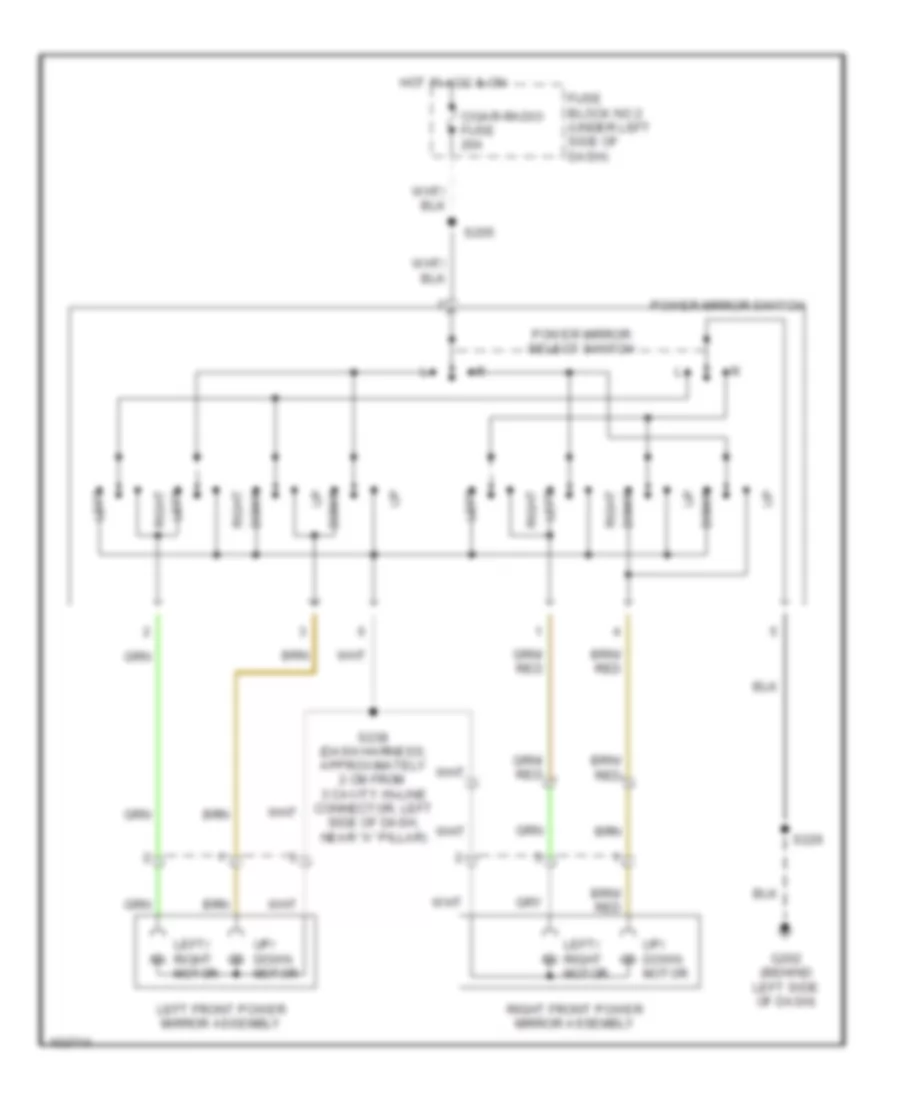
POWER MIRRORS
Power Mirror Wiring Diagram for Chevrolet Tracker 1998
List of elements for Power Mirror Wiring Diagram for Chevrolet Tracker 1998:
- Cigar-radio fuse 20a
- Down
- Fuse block no 2 (under left side of dash)
- G202 (behind left side of dash)
- Hot in acc & on
- Left
- Left front power mirror assembly
- Left/ right motor
- Power mirror select switch
- Power mirror switch
- Right
- Right front power mirror assembly
- S205
- S226
- S238 (dash harness, approximately 2 cm from 3 cavity in-line connector, left side of dash, near "a" pillar)
- Up/ down motor
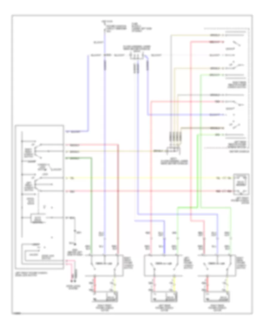
POWER WINDOWS
Power Window Wiring Diagram for Chevrolet Tracker 1998
List of elements for Power Window Wiring Diagram for Chevrolet Tracker 1998:
- (floor harness, under rear center console) sp370
- Auto down control
- Center console
- Door lock switch
- Door locks system
- Down
- Down/ auto down
- Fuse block 2 (under left side of dash)
- G202 (behind left side of dash)
- Hot in on
- Left front power window motor
- Left front power window/ door lock switch
- Left front window switch
- Left rear power window motor
- Left rear power window switch
- Left rear remote power window switch
- Lock
- Pnk
- Power windows circuit breaker 50a
- Red
- Right front power window motor
- Right front power window switch
- Right front window switch
- Right rear power window motor
- Right rear power window switch
- Right rear remote power window switch
- S202
- S501
- Solid state
- Sp371 (floor harness, under rear center console)
- Unlock
- Window lock switch
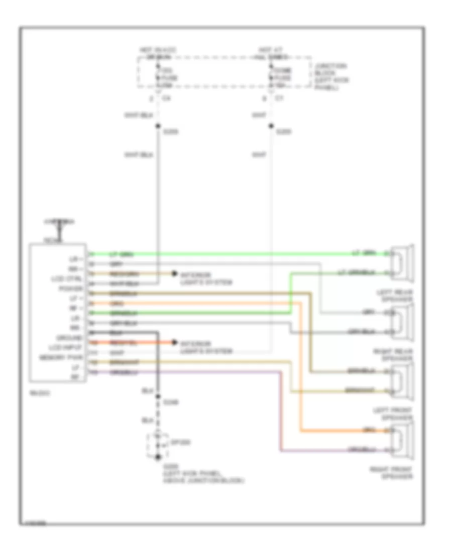
RADIO
Radio Wiring Diagrams for Chevrolet Tracker 1998
List of elements for Radio Wiring Diagrams for Chevrolet Tracker 1998:
- Antenna
- Cig fuse 20a
- Dome fuse 15a
- G200 (left kick panel, above junction block)
- Ground
- Hot at all times
- Hot in acc or run
- Interior lights system
- Junction block (left kick panel)
- Lcd ctrl
- Lcd input
- Left front speaker
- Left rear speaker
- Lf +
- Lf -
- Lr +
- Lr -
- Memory pwr
- Nca
- Power
- Radio
- Rf +
- Rf -
- Right front speaker
- Right rear speaker
- Rr +
- Rr -
- S248
- S255
- S256
- Sp200
SHIFT INTERLOCKS
Shift Interlock Wiring Diagram, 3 Speed A/T & 4 Speed A/T with Cruise for Chevrolet Tracker 1998
List of elements for Shift Interlock Wiring Diagram, 3 Speed A/T & 4 Speed A/T with Cruise for Chevrolet Tracker 1998:
- 3 speed a/t
- 4 speed a/t, w/ cruise control
- Capacitor
- Fuse block 2 (under left side of dash)
- G202 (behind left side of dash)
- Hot at all times
- Hot in on and start
- Nca
- S131
- S206
- S208
- S234
- S251
- S260 (main harn, left side of dash)
- Shift lock relay (right side of eng compt, in front of battery)
- Shift lock solenoid (in center console, under manual selector)
- Stop horn fuse 15a
- Stoplamp switch (top of brake support)
- Transmission range switch (right side of transmission)
- Turn back fuse 15a
- Wiper washer fuse 15a
Shift Interlock Wiring Diagram, 4 Speed A/T without Cruise for Chevrolet Tracker 1998
List of elements for Shift Interlock Wiring Diagram, 4 Speed A/T without Cruise for Chevrolet Tracker 1998:
- C103
- C201
- Capacitor
- Fuse block 2 (under left dash)
- G202 (behind left side of dash)
- Hot in on and start
- Nca
- S208
- S234
- Shift lock solenoid (under center console)
- Stoplamp switch (on brake pedal bracket)
- Transmission range switch (right side of transmission)
- Turn back fuse 15a
STARTING/CHARGING
Charging Wiring Diagram for Chevrolet Tracker 1998
List of elements for Charging Wiring Diagram for Chevrolet Tracker 1998:
- Acc
- Batt fuse 80a
- Battery
- Charge indicator
- Daytime running lamps control module (behind left side of dash)
- Fuse block 1 (right rear of engine compt, front of battery)
- Fuse block 2 (under left side of dash)
- G105 (right inner fender, near battery)
- G120 (right engine, near starter motor)
- Generator
- Ig fuse 60a
- Ig-coil meter fuse 15a
- Ignition switch
- Instrument panel cluster assembly
- Junction connector 2 (under left side of dash)
- Lock
- Run
- S130
- S205
- S241 (main harn, 2cm from pcm connectors breakout)
- S272
- Start
- Starter solenoid
Starting Wiring Diagram for Chevrolet Tracker 1998
List of elements for Starting Wiring Diagram for Chevrolet Tracker 1998:
- 3-speed
- 4-speed
- A/t
- Acc
- Batt fuse 80a
- Battery
- Clutch pedal position switch (on clutch pedal support)
- Cruise control system
- Engine controls system
- Fuse block 1 (right side of engine compt., front of battery)
- G105 (right inner fender, near battery)
- G120 (right engine, near starter motor)
- Ig fuse 60a
- Ignition switch
- Lock
- M/t
- P or n
- Park/ neutral position switch (right side of trans)
- Red
- S100 (main harn, approx. 21 cm from front wiper motor breakout)
- S136
- S248
- Start
- Starter
- Starter solenoid
- Transmission range switch (right side of trans)
SUPPLEMENTAL RESTRAINTS
Supplemental Restraint Wiring Diagram for Chevrolet Tracker 1998
List of elements for Supplemental Restraint Wiring Diagram for Chevrolet Tracker 1998:
- (dash harn, near breakout to pwr mirror switch) s200
- (left rear of pass compt) g400
- (main harn, near breakout to stop lamp sw) s213
- (sub-floor harn, near breakout to seat belt sw-2-door, floor harn, near breakout to g400-4-door)
- Air bag fuse box (under left side of dash)
- Air bag ind
- Computer data lines system
- Data line
- Data link connector obd-ii (right of steering column)
- Dr infl mod
- Fuse block 2 (under left side of dash)
- G206 (center of dash)
- Ground
- Hot in on or start
- Ig-coil meter fuse 15a
- Ignition
- Ind ctrl
- Inflatable restraint dash module (upper right side of dash)
- Inflatable restraint data link connector (under steering column)
- Inflatable restraint sensing and diagnostic module (under center of dash)
- Inflatable restraint steering wheel module (in steering wheel)
- Instrument panel cluster assembly
- Low pres
- Not used
- Pass infl hi
- Pass infl lo
- Seat belt ind
- Seat belt switch
- Shorting bar
- Sir ig fuse 15a
- St belt sw
- Warning systems
TRANSMISSION
1.6L
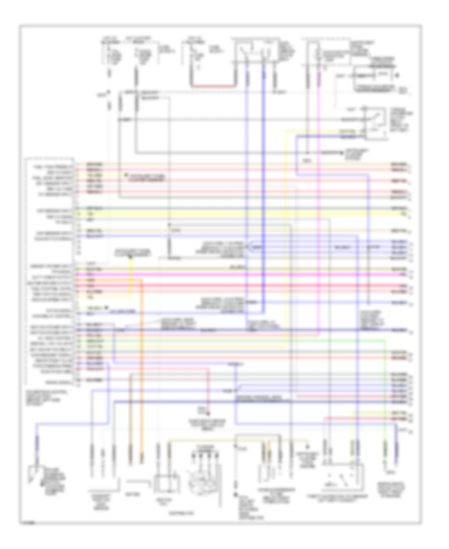
1.6L (VIN 6), 3 Speed A/T Wiring Diagram, 3L30-E for Chevrolet Tracker 1998
List of elements for 1.6L (VIN 6), 3 Speed A/T Wiring Diagram, 3L30-E for Chevrolet Tracker 1998:
- Anti-lock brakes, cruise control, shift
- Antilock brakes, cruise control engine controls, headlights (drl), starting/charging, systems
- Automatic transmission (3l30-e)
- Engine controls system
- Exterior lights system
- Fi fuse 15a
- Fuse block 1
- Fuse block 2
- Horn relay
- Hot at all times
- Hot in on & start
- Ig-coil meter fuse 15a
- Interlock
- Main relay (under center of dash, behind blower selector switch)
- Main relay control
- Powertrain control module (behind left side of dash)
- S210
- S227
- S251
- S254
- S260
- S272
- S295 (main harn, 7 cm from blower speed selector switch breakout)
- S411
- Stop horn fuse 15a
- Stoplamp switch (above brake pedal)
- Stoplamp switch input
- Systems
- Tcc relay control
- Torque converter clutch relay (right side of engine compt, forward of battery)
- Torque converter clutch solenoid
- Trailer harness connector (partial)
1.6L (VIN 6), 4 Speed A/T Wiring Diagram, 03-72LE for Chevrolet Tracker 1998
List of elements for 1.6L (VIN 6), 4 Speed A/T Wiring Diagram, 03-72LE for Chevrolet Tracker 1998:
- (floor harn, left rear of passenger compt)
- (main harn, 4 cm from stoplamp switch breakout)
- (main harn, 6 cm from noise filter breakout)
- (right of steering column)
- +5v reference
- 2-position signal
- 4wd-lo signal
- Anti-lock brake system resistor & combination switch
- Anti-lock brakes, cruise control & shift interlock systems
- Antilock brakes, cruise control engine controls, headlights (drl), starting/charging, systems
- Automatic transmission (03-72le)
- Battery
- Brake signal
- C101 red
- C103
- Cruise control system
- D-position signal
- Data link connector (obd-ii) (partial)
- Data link connector, dome lamp, electronic brake control module, ignition key warning switch & radio
- Diagnostic req signal
- Duty check data link connector 1 (partial) (behind right headlamp)
- Duty check output
- Engine controls system
- Exterior lights system
- Fi fuse 15a
- Four wheel drive low switch (top of transfer case)
- Fuse block 1 (right side of engine compt)
- Fuse block 2 (under left side of dash)
- G131 (right rear of engine on intake manifold)
- G202 (above fuse block 2)
- Horn relay
- Hot at all times
- Hot in on or start
- Idle
- Ig-coil meter fuse 15a
- Ignition
- Illumin- ation lamp
- Instrument panel cluster assembly
- Interior lights system
- L-position signal
- Main relay (behind glove box)
- Main relay ctrl
- Malfunction indicator lamp
- Mil ctrl
- N-postion signal
- Nca
- Norm
- O/d off ind ctrl
- O/d off indicator
- O/d signal
- Overdrive switch
- Pcm ground
- Pcm/shield ground
- Pnk
- Power ind ctrl
- Power indicator
- Power/ normal switch
- Power/normal signal
- Powertrain control module (left side of dash)
- Pwr
- R-position signal
- Red
- S107
- S108
- S112
- S122
- S139
- S140
- S205/s204
- S208
- S210
- S215 (main harn, near pcm conn c2 breakout)
- S219
- S234
- S251
- S254
- S260
- S262
- S272
- S276
- S287
- S299
- S411
- Sensor return
- Serial data
- Shift sol 1 ctrl
- Shift sol 2 ctrl
- Shift solenoid
- Stop horn fuse 15a
- Stoplamp switch
- Tail dome fuse 15a
- Tcc sol ctrl
- Test sw signal
- Throttle position sensor
- Torque converter clutch solenoid
- Tp idle sw signal
- Tps signal
- Trailer harness connector (partial)
- Transmission range switch (right side of transmission)
- Turn back fuse 15a
- Vehicle speed sensor (inside speedometer head)
- Vehicle speed sensor (left side of transmission)
- Vehicle speed signal
- Vss signal (+)
- Vss signal (-)
1.6L VIN 6, A/T Wiring Diagram, 03-72LE for Chevrolet Tracker 1998
List of elements for 1.6L VIN 6, A/T Wiring Diagram, 03-72LE for Chevrolet Tracker 1998:
- (floor harn, left rear of passenger compt)
- (main harn, 4 cm from stoplamp switch breakout)
- (main harn, 6 cm from noise filter breakout)
- (right of steering column)
- +5v reference
- 2-position signal
- 4wd-lo signal
- Anti-lock brake system resistor & combination switch
- Anti-lock brakes, cruise control & shift interlock systems
- Antilock brakes, cruise control engine controls, headlights (drl), starting/charging, systems
- Automatic transmission (03-72le)
- Battery
- Brake signal
- C101 red
- C103
- Cruise control system
- D-position signal
- Data link connector (obd-ii) (partial)
- Data link connector, dome lamp, electronic brake control module, ignition key warning switch & radio
- Diagnostic req signal
- Duty check data link connector 1 (partial) (behind right headlamp)
- Duty check output
- Engine controls system
- Exterior lights system
- Fi fuse 15a
- Four wheel drive low switch (top of transfer case)
- Fuse block 1 (right side of engine compt)
- Fuse block 2 (under left side of dash)
- G131 (right rear of engine on intake manifold)
- G202 (above fuse block 2)
- Horn relay
- Hot at all times
- Hot in on or start
- Idle
- Ig-coil meter fuse 15a
- Ignition
- Illumin- ation lamp
- Instrument panel cluster assembly
- Interior lights system
- L-position signal
- Main relay (behind glove box)
- Main relay ctrl
- Malfunction indicator lamp
- Mil ctrl
- N-postion signal
- Nca
- Norm
- O/d off ind ctrl
- O/d off indicator
- O/d signal
- Overdrive switch
- Pcm ground
- Pcm/shield ground
- Pnk
- Power ind ctrl
- Power indicator
- Power/ normal switch
- Power/normal signal
- Powertrain control module (left side of dash)
- Pwr
- R-position signal
- Red
- S107
- S108
- S112
- S122
- S139
- S140
- S205/s204
- S208
- S210
- S215 (main harn, near pcm conn c2 breakout)
- S219
- S234
- S251
- S254
- S260
- S262
- S272
- S276
- S287
- S299
- S411
- Sensor return
- Serial data
- Shift sol 1 ctrl
- Shift sol 2 ctrl
- Shift solenoid
- Stop horn fuse 15a
- Stoplamp switch
- Tail dome fuse 15a
- Tcc sol ctrl
- Test sw signal
- Throttle position sensor
- Torque converter clutch solenoid
- Tp idle sw signal
- Tps signal
- Trailer harness connector (partial)
- Transmission range switch (right side of transmission)
- Turn back fuse 15a
- Vehicle speed sensor (inside speedometer head)
- Vehicle speed sensor (left side of transmission)
- Vehicle speed signal
- Vss signal (+)
- Vss signal (-)
1.6L VIN 6, TCC Solenoid Wiring Diagram, 3L30-E for Chevrolet Tracker 1998
List of elements for 1.6L VIN 6, TCC Solenoid Wiring Diagram, 3L30-E for Chevrolet Tracker 1998:
- Anti-lock brakes, cruise control, shift
- Antilock brakes, cruise control engine controls, headlights (drl), starting/charging, systems
- Automatic transmission (3l30-e)
- Engine controls system
- Exterior lights system
- Fi fuse 15a
- Fuse block 1
- Fuse block 2
- Horn relay
- Hot at all times
- Hot in on & start
- Ig-coil meter fuse 15a
- Interlock
- Main relay (under center of dash, behind blower selector switch)
- Main relay control
- Powertrain control module (behind left side of dash)
- S210
- S227
- S251
- S254
- S260
- S272
- S295 (main harn, 7 cm from blower speed selector switch breakout)
- S411
- Stop horn fuse 15a
- Stoplamp switch (above brake pedal)
- Stoplamp switch input
- Systems
- Tcc relay control
- Torque converter clutch relay (right side of engine compt, forward of battery)
- Torque converter clutch solenoid
- Trailer harness connector (partial)
WARNING SYSTEMS
Warning System Wiring Diagrams for Chevrolet Tracker 1998
List of elements for Warning System Wiring Diagrams for Chevrolet Tracker 1998:
- (2-door)
- (4 door) (floor harn, approc 50 cm from g314 breakout)
- (4-door)
- Audio alarm module (behind right sid of dash, near front speaker)
- Combination switch
- Dr open
- Exterior/ interior lights system
- From power mirror switch connector breakout) s200
- Fuse block 2 (under left side of dash)
- G201 (behind right side of dash)
- G202 (behind left side of dash)
- G314 (left rear passenger compt, behind trim panel)
- Head
- Headlamp relay 2
- Hot at all times
- Hot in on and start
- Ig-coil meter fuse 15a
- Ign key sig
- Ignition
- Ignition key warning switch
- Instrument panel cluster assembly
- Interior lights system
- Left door jamb switch (left door frame)
- Off
- Park
- S204
- S212
- S214
- S216
- S221 (i/p harn, approx 12 cm from cigar lighter breakout)
- S226
- S250
- S272
- S404
- S406
- S425 s300 (2-door) (main harn, 10 cm from left rear speaker conn breakout)
- Seat belt ind
- Seat belt switch
- St blt ind
- Tail dome fuse 15a
WIPER/WASHER
2-Speed Wiper/Washer Wiring Diagram for Chevrolet Tracker 1998
List of elements for 2-Speed Wiper/Washer Wiring Diagram for Chevrolet Tracker 1998:
- (right front fender, near washer fluid reservoir) g101
- Combination switch
- Front washer pump (on washer fluid reservoir)
- Front wiper motor (left side of firewall)
- Fuse block 2 (under left side of dash)
- G116 (left bulkhead, near front wiper motor)
- High
- Hot in on and start
- Lo off
- Off
- Park
- Run
- S104
- S206
- Washer switch
- Wiper motor
- Wiper switch
- Wiper washer fuse 15a
Intermittent Wiper/Washer Wiring Diagram for Chevrolet Tracker 1998
List of elements for Intermittent Wiper/Washer Wiring Diagram for Chevrolet Tracker 1998:
- Combination switch
- Front washer pump (on washer fluid reservoir)
- Front wiper motor (left side of firewall)
- Fuse block 2 (behind left side of dash)
- G101 (right front fender, near washer fluid reservoir)
- G116 (left bulkhead, near front wiper motor)
- G206 (center of dash)
- Hot in on and start
- Int
- Int off
- Inter- mittent controller
- Off
- Park
- Run
- S104
- S206
- S229
- Washer switch
- Wiper switch
- Wiper washer fuse 15a
Rear Wiper/Washer Wiring Diagram for Chevrolet Tracker 1998
List of elements for Rear Wiper/Washer Wiring Diagram for Chevrolet Tracker 1998:
- Fuse block 2 (under left side of dash)
- G101 (right front fender, near washer fluid reservoir)
- G407 (rear door harn, near rear wiper motor)
- Hot in on and start
- Interior lights system
- Off
- Park
- Rear washer pump (washer fluid reservoir)
- Rear washer switch
- Rear wiper motor (center of rear door)
- Rear wiper switch
- Rear wiper/ washer switch
- Run
- S104
- S236
- Wiper washer fuse 15a

 Čeština
 Dansk
Dansk Deutsch
 Ελληνικά
 English
 English
 Español
 Suomi
Suomi Français
 Français
 עברית
עברית Hrvatski
 Magyar
 Italiano
 日本語
日本語 한국어
한국어 Polski
 Português
 Português
 Română
 Русский
 Slovenčina
 Slovenščina
 Svenska
 Türkçe
 中文 (中国)