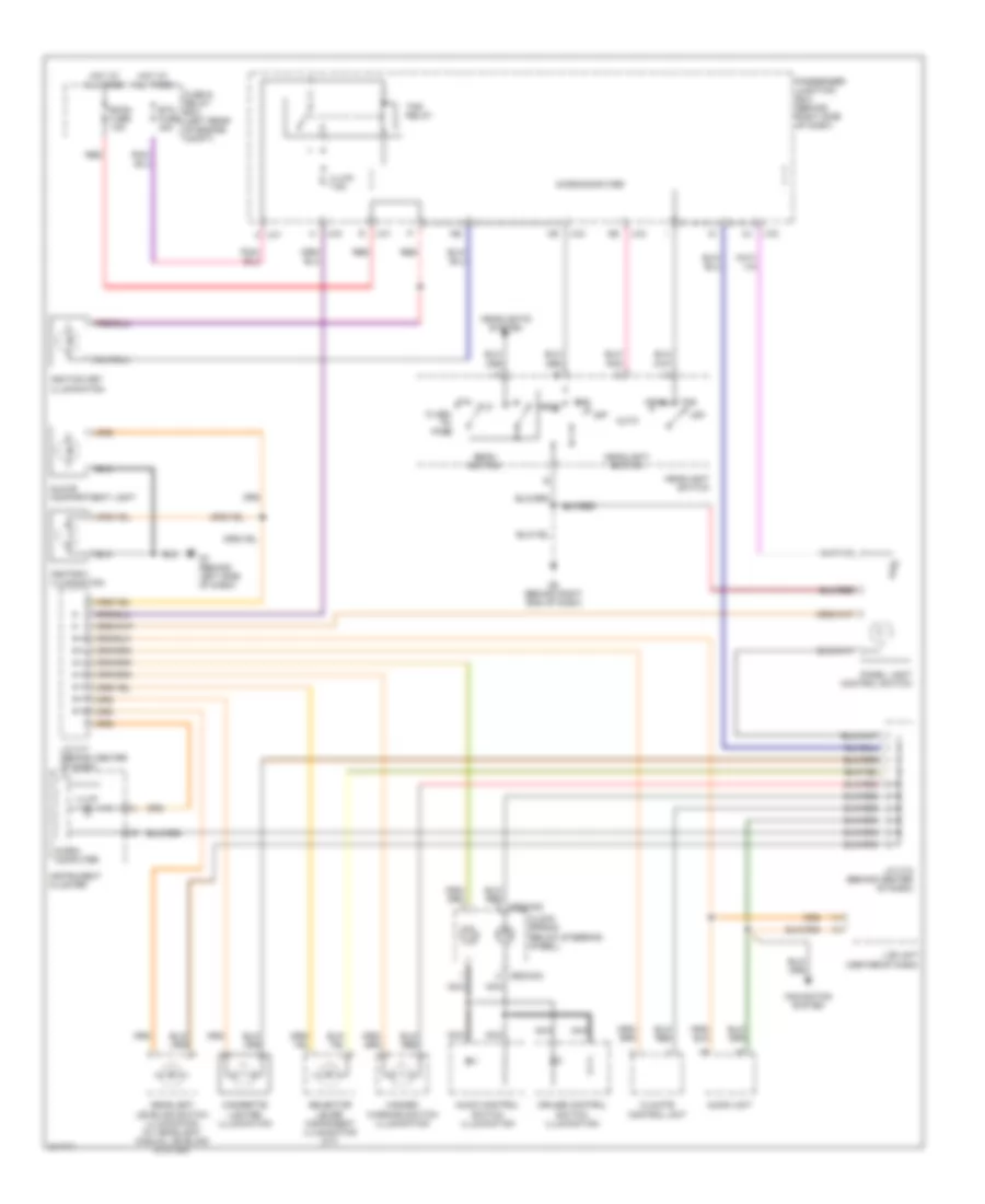
AIR CONDITIONING
Heater Wiring Diagram for Mazda 3 i 2005
 https://portal-diagnostov.com/license.html
Automotive Electricians Portal FZCO
Automotive Electricians Portal FZCO
https://portal-diagnostov.com/license.html
https://portal-diagnostov.com/license.html
Automotive Electricians Portal FZCO
Automotive Electricians Portal FZCO
List of elements for Heater Wiring Diagram for Mazda 3 i 2005:
- (behind left headlight) g1
- (behind left side of dash) g7
- A/c fuse 10a
- Blower motor (behind right side of dash)
- Blower relay (in fuse and relay box)
- Climate control unit
- Defogger system
- Fan switch
- Fuse and relay box (left rear of engine compt)
- Heater fuse 40a
- Hot at all times
- Hot in run
- J-01
- Passenger junction box (behind right side of dash)
- Red
- Resistor (behind right side of dash)
- W/o a/c
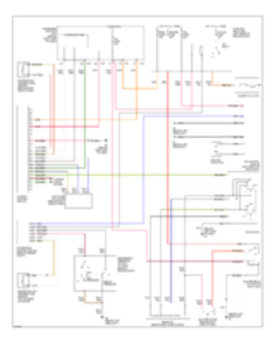
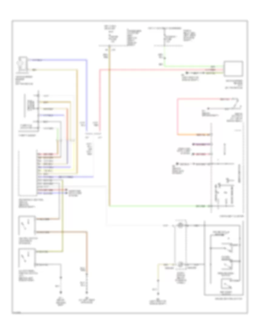
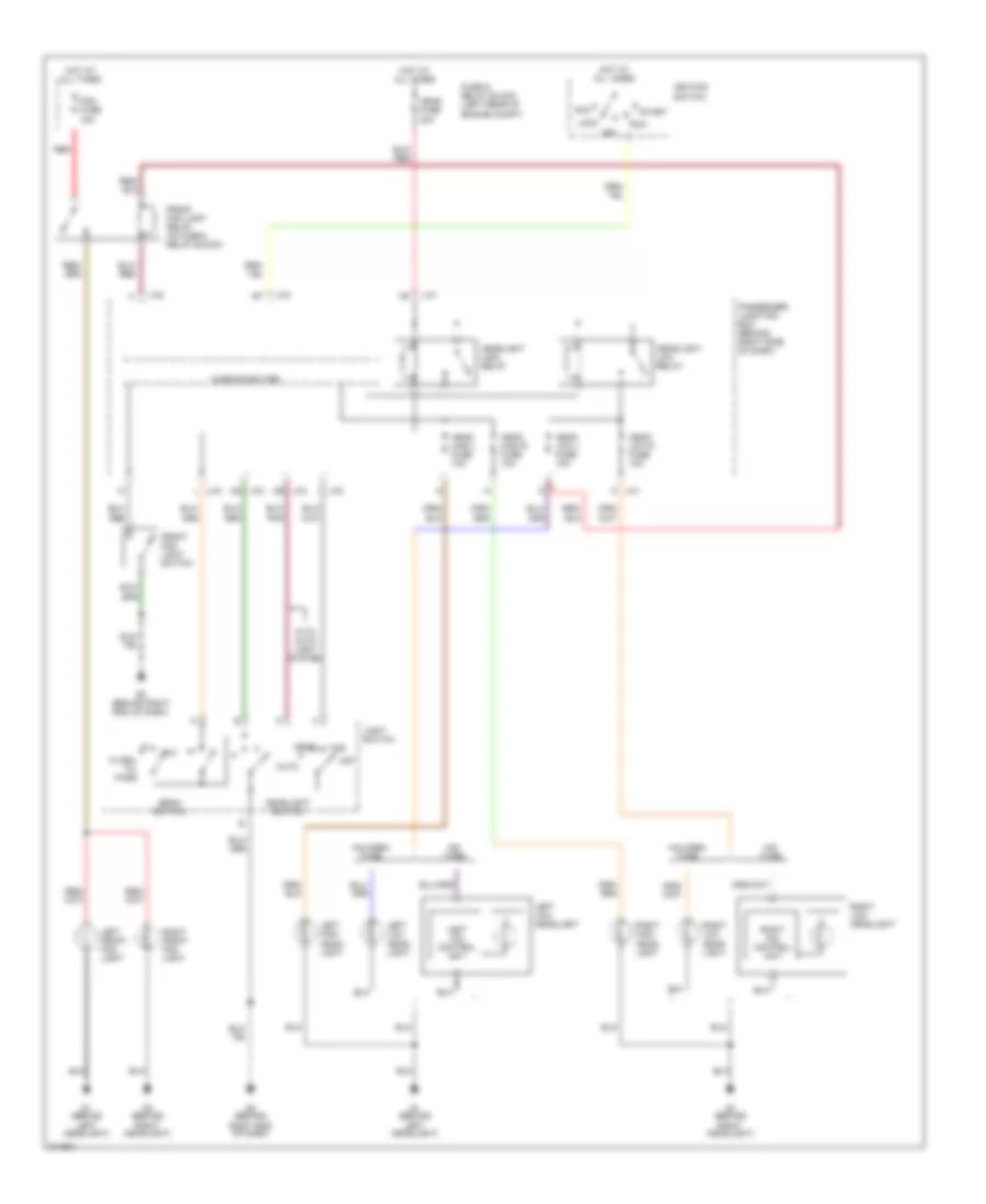
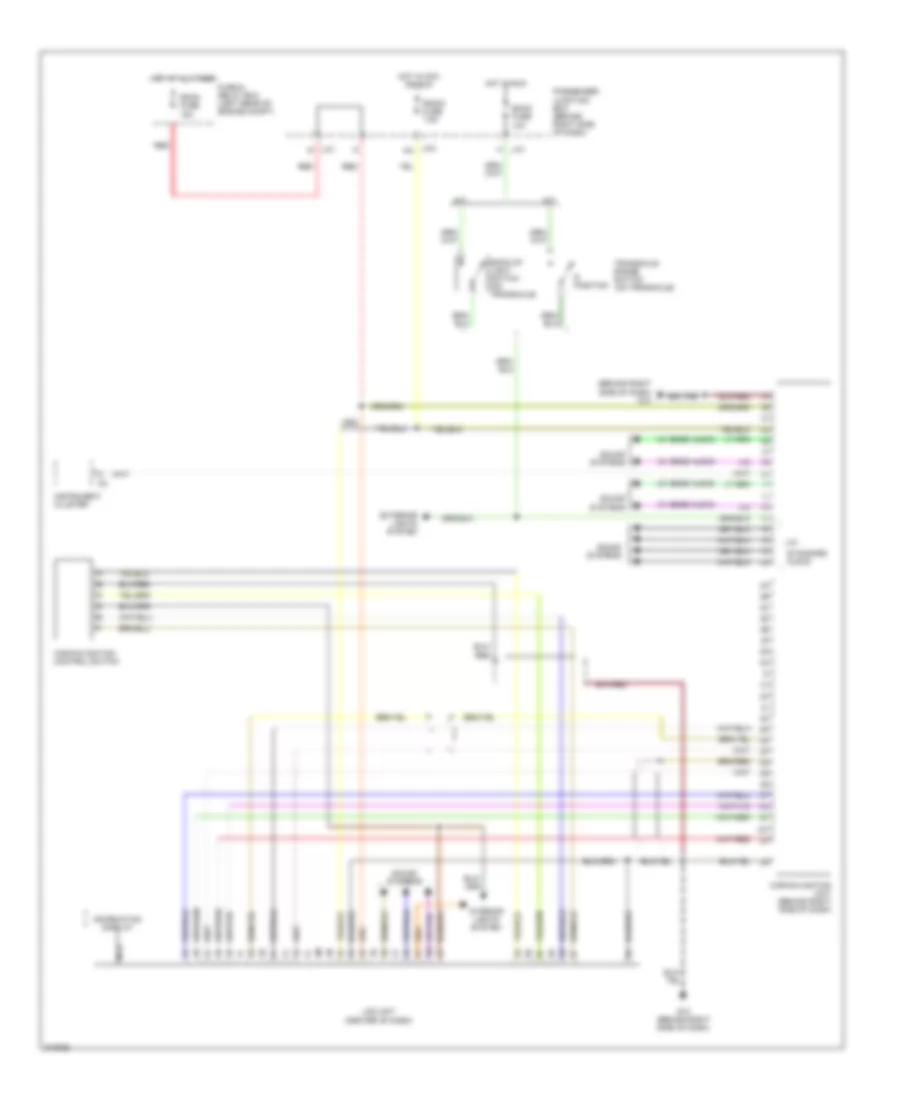
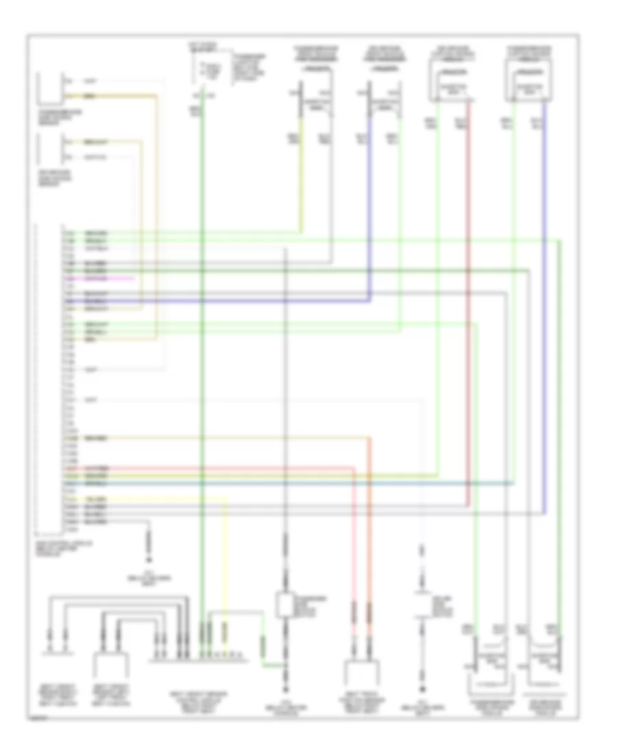
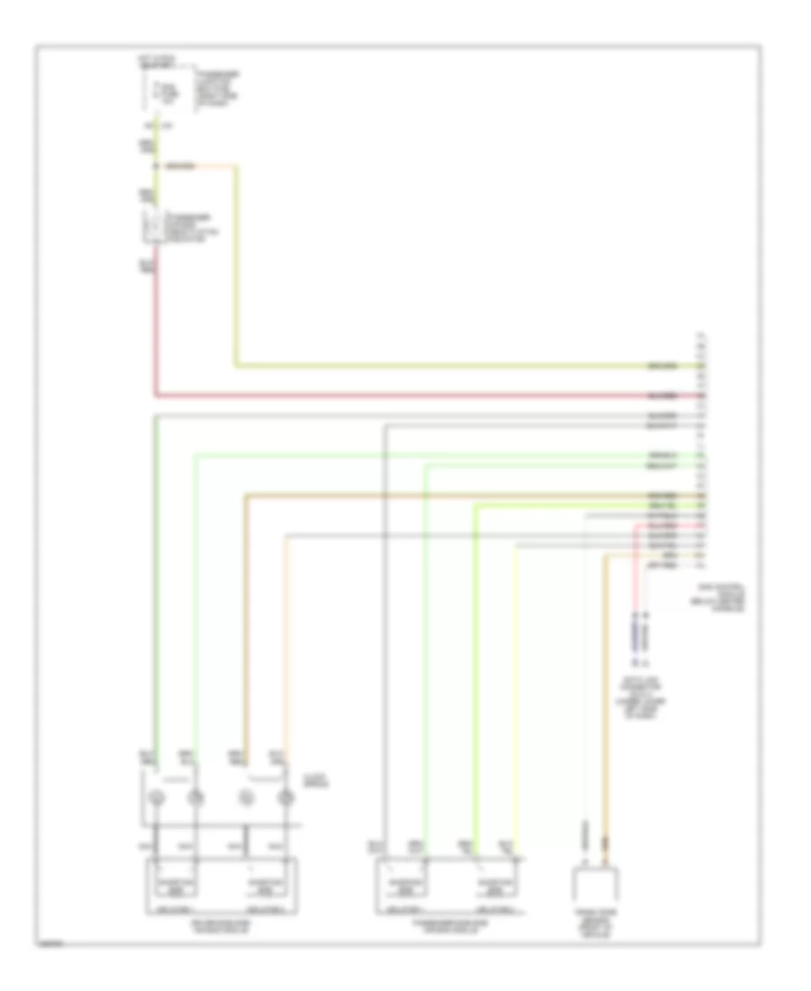
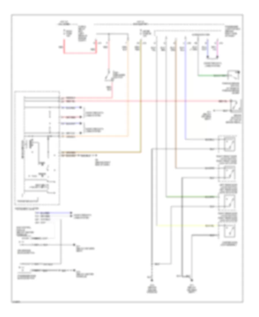
Manual A/C Wiring Diagram for Mazda 3 i 2005
List of elements for Manual A/C Wiring Diagram for Mazda 3 i 2005:
- (behind left headlight) g1
- (behind left side of dash) g7
- 1an
- 1ap
- 2aa
- 2ak
- A/c fuse 10a
- A/c mag fuse 10a
- A/c relay
- Air intake actuator (behind right side of dash)
- Blower motor (behind right side of dash)
- Blower relay (in fuse and relay box)
- Climate control module
- Cooling fan motor
- Engine coolant temperature sensor (on top rear of engine)
- Evaporator temperature sensor (behind right side of dash)
- Fan control module (left front of eng compt)
- Fan fuse 40a
- Fan switch
- Fuse and relay box (left rear of engine compt)
- G1 (behind left headlight)
- G2 (behind left headlight)
- G8 (behind right end of dash)
- Heater fuse 40a
- High & low pressure
- Hot at all times
- Hot in run
- Interior lights system
- J-01
- J-03
- J-04
- Magnetic clutch
- Medium pressure
- Microcomputer
- Nca
- Passenger junction box (behind right side of dash)
- Pnk
- Pnk/ red
- Pnk/red
- Powertrain control module (rear of engine compt)
- Red
- Refrigerant pressure switch (at right rear of engine compt)
- Resistor (behind right side of dash)
- Room fuse 15a
ANTI-LOCK BRAKES
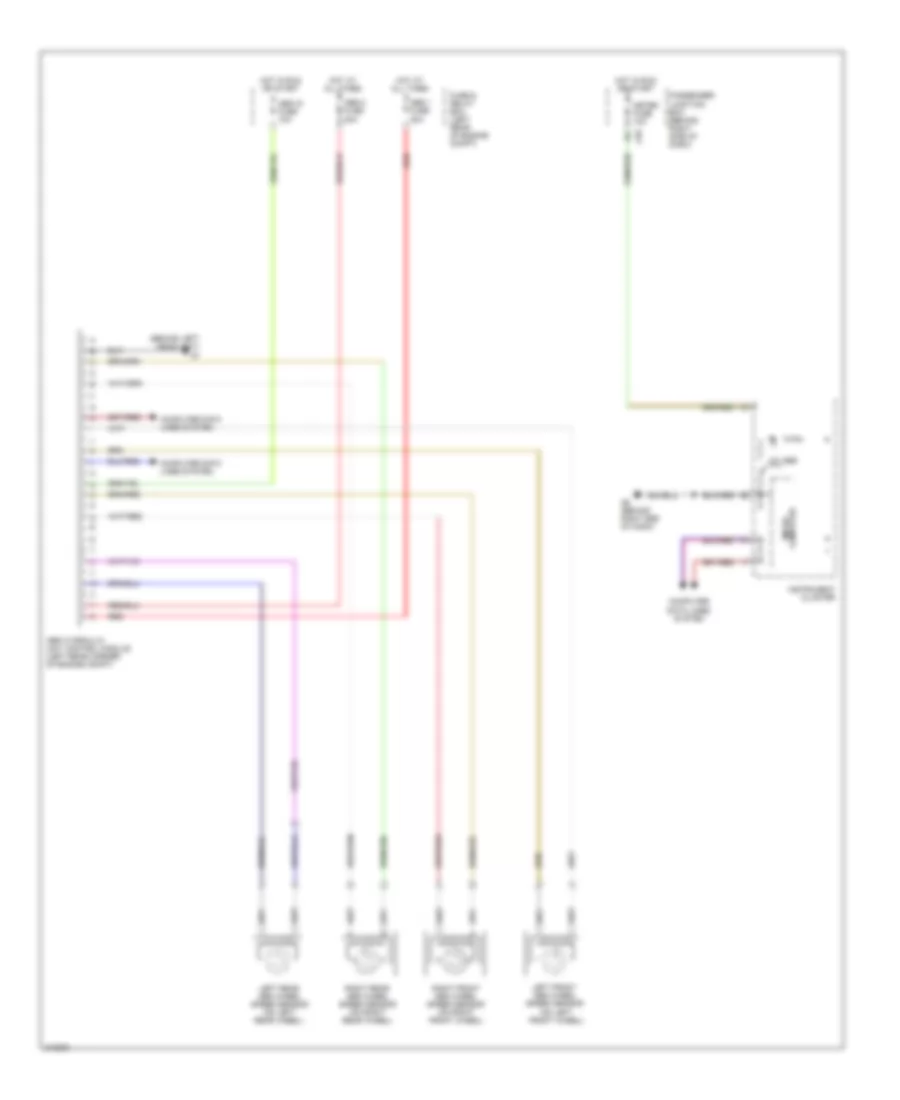
Anti-lock Brakes Wiring Diagram for Mazda 3 i 2005
List of elements for Anti-lock Brakes Wiring Diagram for Mazda 3 i 2005:
- (behind left headlight) g1
- (on left front wheel)
- 4w abs
- Abs 1 fuse 30a
- Abs 2 fuse 20a
- Abs hydraulic unit control module (left rear corner of engine compt)
- Abs ig fuse 10a
- Computer data lines system
- Fuse & relay box (left rear of engine compt)
- G8 (behind right end of dash)
- Hot at all times
- Hot in run or start
- Instrument cluster
- J-03
- Left front abs wheel speed sensor
- Left rear abs wheel speed sensor (on left rear wheel)
- Meter fuse 10a
- Micro- computer
- Passenger junction box (behind right side of dash)
- Red
- Right front abs wheel speed sensor (on right front wheel)
- Right rear abs wheel speed sensor (on right rear wheel)
ANTI-THEFT
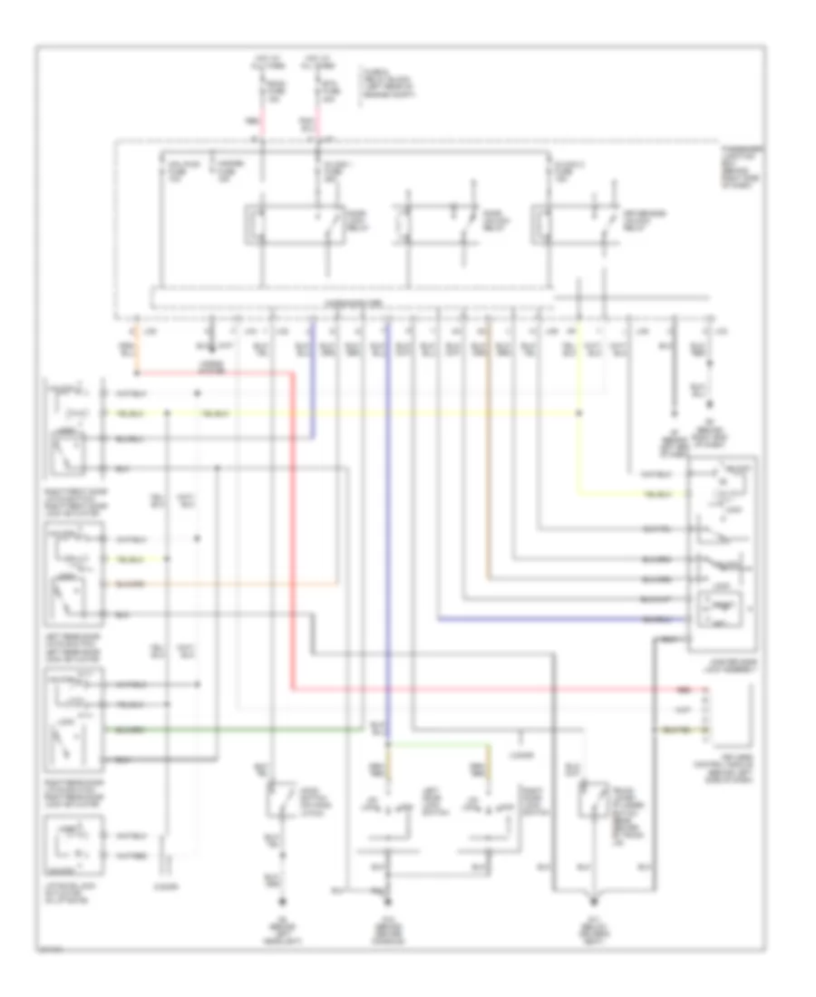
Anti-theft Alarm Wiring Diagram for Mazda 3 i 2005
List of elements for Anti-theft Alarm Wiring Diagram for Mazda 3 i 2005:
- 4 door
- 5 door
- Btn fuse 40a
- Cpu pwr fuse 10a
- D/lock 1 fuse 25a
- D/lock 2 fuse 15a
- Door lock relay
- Door unlock relay
- Driver-side unlock relay
- Fuse & relay block (left rear of engine compt)
- G11 (below driver's seat)
- G12 (behind center console)
- G2 (behind left headlight)
- G7 (behind left end of dash)
- G8 (behind right end of dash)
- Hazard fuse 15a
- Hood switch (on hood latch)
- Horns system
- Hot at all times
- J-01
- J-02
- J-03 c
- J-04
- J-05
- J-06
- Keyless control module (behind left side of dash)
- Left door lock switch
- Left rear door latch switch/ left rear door lock actuator
- Liftgate lock actuator (in liftgate)
- Lock
- Master door lock assembly
- Microcomputer
- Passenger junction box (behind right side of dash)
- Red
- Reset
- Right door lock switch
- Right front door latch switch/ right front door lock actuator
- Right rear door latch switch/ right rear door lock actuator
- Room fuse 15a
- Set
- Trunk lid key cylinder switch (rear center of trunk lid)
- Un- lock
- Unlock
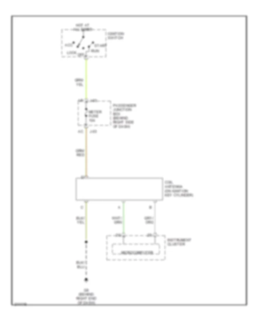
Immobilizer Wiring Diagram for Mazda 3 i 2005
List of elements for Immobilizer Wiring Diagram for Mazda 3 i 2005:
- Acc
- Coil antenna (on ignition key cylinder)
- G8 (behind right end of dash)
- Hot at all times
- Ignition switch
- Instrument cluster
- J-03
- Lock
- Meter fuse 10a
- Microcomputer
- Off
- Passenger junction box (behind right side of dash)
- Run
- Start
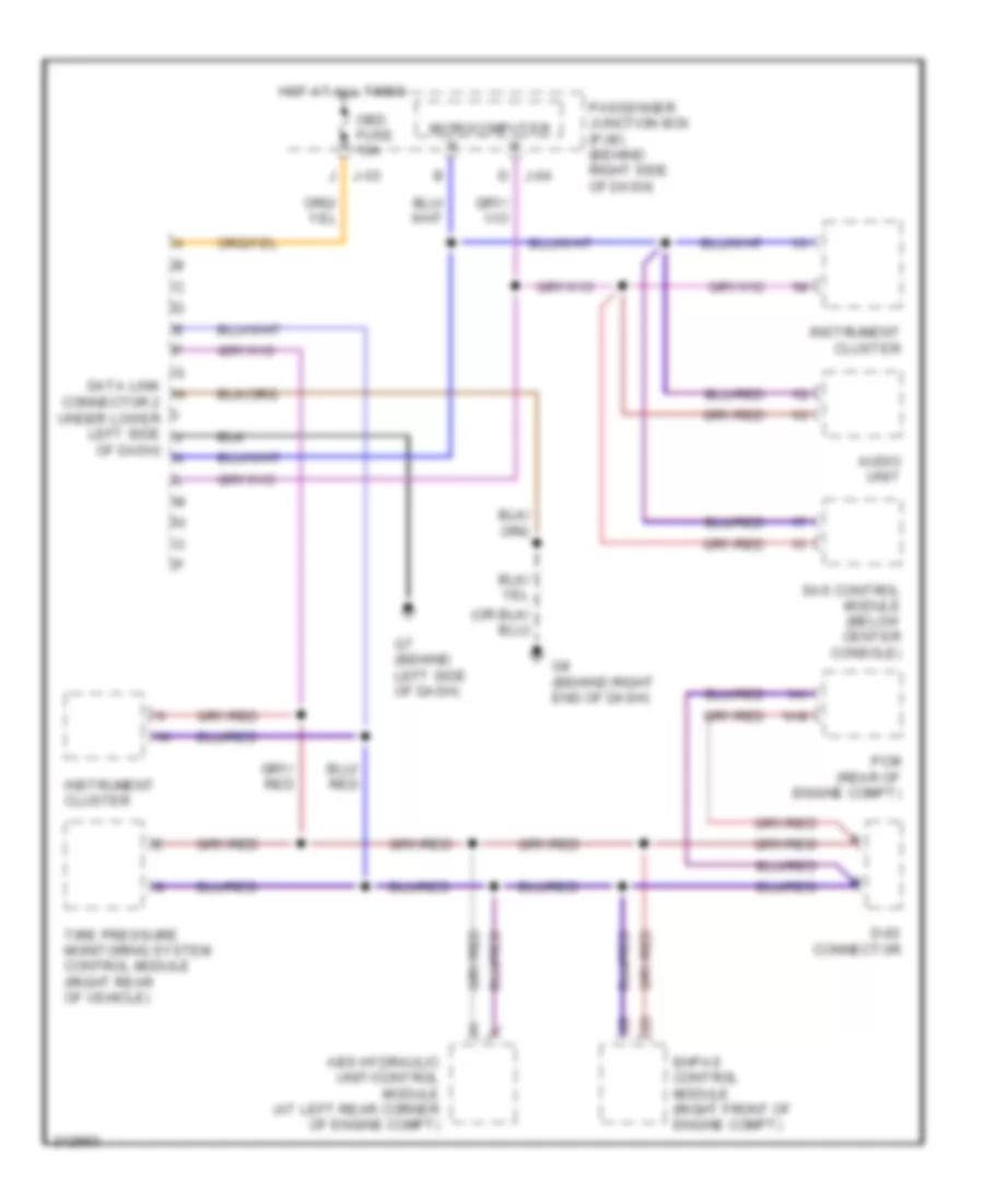
COMPUTER DATA LINES
Computer Data Lines Wiring Diagram for Mazda 3 i 2005
List of elements for Computer Data Lines Wiring Diagram for Mazda 3 i 2005:
- 1ai
- 1am
- Abs hydraulic unit/control module (at left rear corner of engine compt)
- Audio unit
- D j-04
- D-02 connector
- Data link h connector 2 under lower left side j
- Ehpas control module (right front of engine compt)
- G7 (behind left side of dash)
- G8 (behind right end of dash)
- Hot at all times
- Instrument cluster
- J j-03
- Microcomputer
- Obd fuse 10a
- Of dash) k
- Passenger junction box (pjb) (behind right side of dash)
- Pcm (rear of engine compt)
- Sas control module (below center console)
- Tire pressure monitoring system control module (right rear of vehicle)
COOLING FAN
Cooling Fan Wiring Diagram for Mazda 3 i 2005
List of elements for Cooling Fan Wiring Diagram for Mazda 3 i 2005:
- 2ak
- A22
- Cooling fan motor
- Engine coolant temperature sensor (on top rear of eng)
- Fan control module (left front of eng compt)
- Fan fuse 40a
- Fuse and relay box (left rear of engine compt)
- G1 (behind left headlight)
- G2 (behind left headlight)
- Hot at all times
- Nca
- Pnk/ red
- Pnk/red
- Powertrain control module (rear of eng compt)
CRUISE CONTROL
Cruise Control Wiring Diagram for Mazda 3 i 2005
List of elements for Cruise Control Wiring Diagram for Mazda 3 i 2005:
- (left front of engine compt)
- 0922-202
- 0922-203
- 1ad
- 1ai
- 1am
- A/t
- Brake switch 2 (at top of brake pedal)
- Cancel switch
- Clock- spring (below steering wheel)
- Clutch pedal position switch (m/t) (behind left side of dash)
- Computer data lines system
- Cruise control switch
- Cruise main ind
- Cruise main switch
- Cruise set ind
- Driver's seat
- Eng bar 1 fuse 10a
- Fuse & relay box (left rear of engine compt)
- G11 (below
- G11 (below driver's seat)
- G5 (left front of engine compt)
- G6 (at left rear of engine)
- G8 (behind right end of dash)
- Hot in run or start
- Hot w/ main relay energized
- Instrument cluster
- J-03
- M/t
- Meter fuse 10a
- Microcomputer
- Nca
- Neutral switch (near rear of engine)
- Passenger junction box (behind right side of dash)
- Position throttle
- Powertrain control module (rear of engine compt)
- Resume/accel switch
- Sensor
- Set/coast switch
- Throttle actuator
- Throttle body
- Vehicle speed sensor (a/t) (on transaxle)
- Vehicle speed sensor (m/t) (on transaxle)
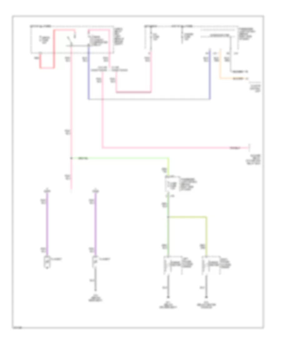
DEFOGGERS
Defoggers Wiring Diagram for Mazda 3 i 2005
List of elements for Defoggers Wiring Diagram for Mazda 3 i 2005:
- A/c fuse 10a
- Blower relay (in fuse and relay box)
- Climate control unit
- Defog fuse 40a
- Door
- Filament
- Fuse & relay box (left rear of engine compt)
- G11 (below driver's seat)
- G12 (below center console)
- G14 (behind rear seat)
- Hazard fuse 15a
- Hot at all times
- Hot in run
- J-01 i
- J-01 n
- J-04
- Left power outside mirror
- M def fuse 7.5a
- Microcomputer
- Mirror heater
- Passenger junction box (behind right side of dash)
- Rear window defroster relay
- Red
- Right power outside mirror
- W/ air conditioning
- W/o air conditioning
- Z j-05
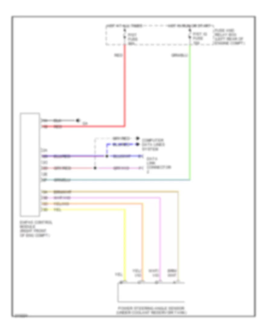
ELECTRONIC POWER STEERING
Electronic Power Steering Wiring Diagram for Mazda 3 i 2005
List of elements for Electronic Power Steering Wiring Diagram for Mazda 3 i 2005:
- Computer data lines system
- Data link connector
- Ehpas control module (right front of eng compt)
- Fuse and relay box (left rear of engine compt)
- Hot at all times
- Hot in run or start
- P/st fuse 80a
- P/st ig fuse 10a
- Power steering angle sensor (under coolant reservoir tank)
- Red
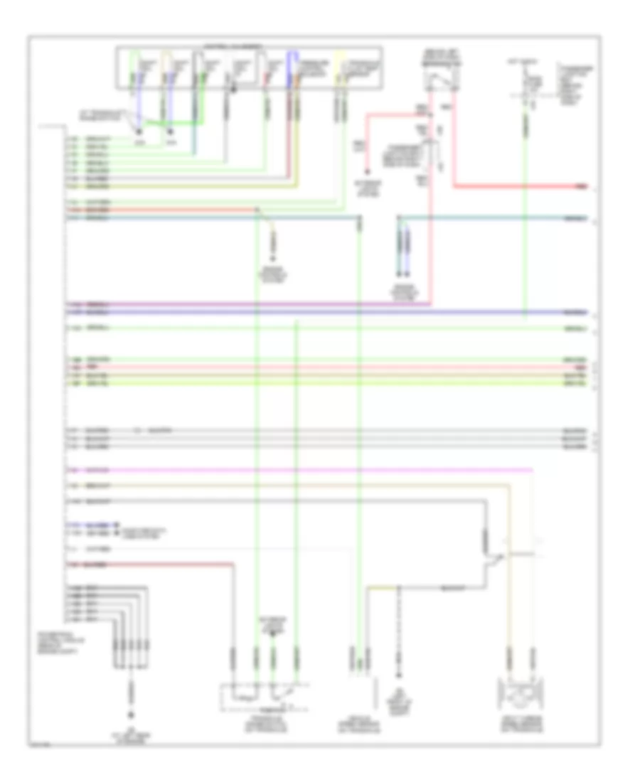
ENGINE PERFORMANCE
2.0L
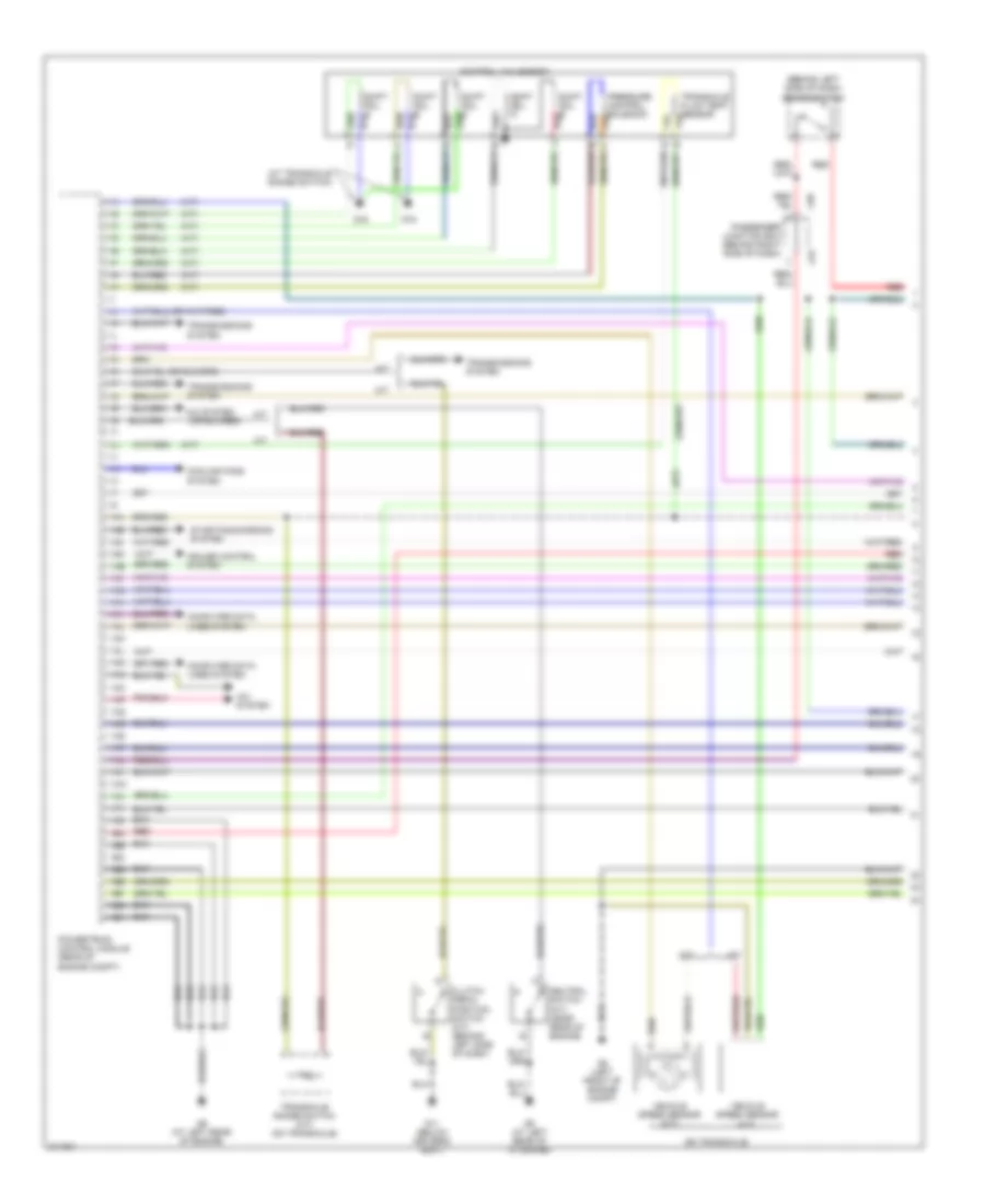
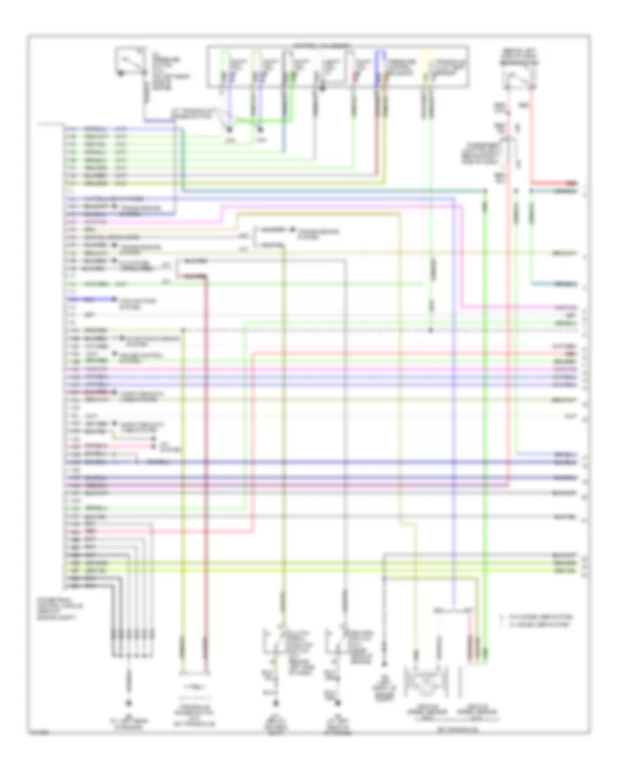
2.0L, Engine Performance Wiring Diagram, California (1 of 4) for Mazda 3 i 2005
List of elements for 2.0L, Engine Performance Wiring Diagram, California (1 of 4) for Mazda 3 i 2005:
- (a/t)
- (at transaxle range switch)
- (behind left side of dash) brake switch
- (on transaxle)
- 1aa
- 1ab
- 1ac
- 1ad
- 1ae
- 1af
- 1ag
- 1ah
- 1ai
- 1aj
- 1ak
- 1al
- 1am
- 1an
- 1ao
- 1ap
- 1aq
- 1ar
- 1as
- 1at
- 1au
- 1av
- 1aw
- 1ax
- 1ay
- 1az
- 1ba
- 1bb
- 1bc
- 1bd
- 1be
- 1bf
- 1bg
- 1bh
- A/c system
- A/t
- Clutch pedal position switch (m/t) (behind left side of dash)
- Computer data lines system
- Control valve body
- Cooling fans system
- Cruise control system
- G11 (below driver's seat)
- G16
- G5 (left front of engine compt)
- G6 (at left rear of engine)
- G6 (at left rear of of engine)
- J-01
- J-05
- M/t
- Neutral switch (m/t) (near rear of engine)
- Passenger junction box (behind right side of dash)
- Powertrain control module (rear of engine compt)
- Pressure control solenoid
- Red
- Shift sol a
- Shift sol b
- Shift sol c
- Shift sol d
- Shift sol e
- Starting/charging system
- Transaxle fluid temp sensor
- Transaxle range switch (a/t) (on transaxle)
- Transmissions system
- Vehicle speed sensor (a/t)
- Vehicle speed sensor (m/t)
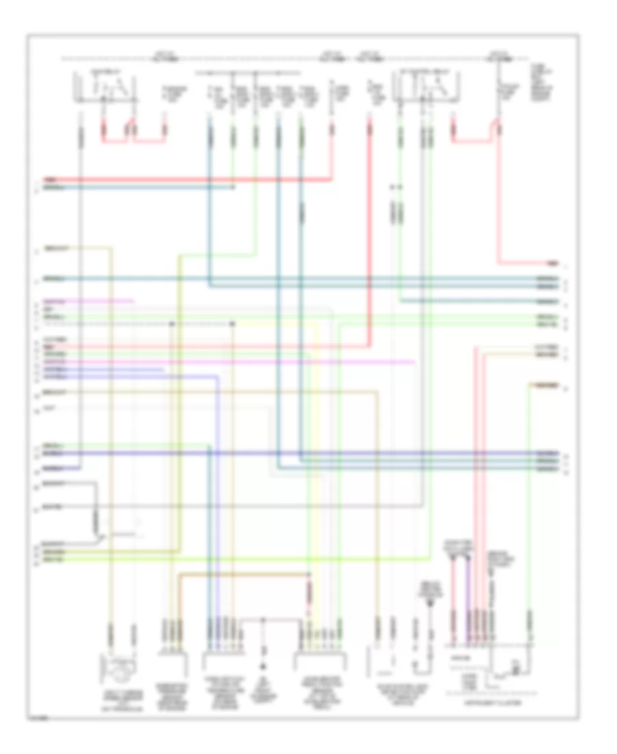
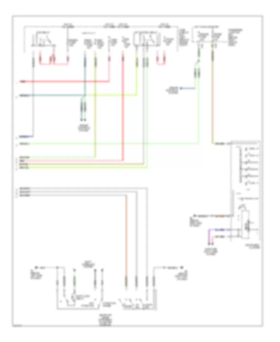
2.0L, Engine Performance Wiring Diagram, California (2 of 4) for Mazda 3 i 2005
List of elements for 2.0L, Engine Performance Wiring Diagram, California (2 of 4) for Mazda 3 i 2005:
- (behind right end of dash) g8
- (below center console) g12
- Accelerator pedal position sensor (at top of accelerator pedal)
- Barometric pressure sensor (near rear of engine)
- Computer data lines system
- Egi inj fuse 10a
- Eng + b fuse 10a
- Eng bar 1 fuse 10a
- Eng bar 2 fuse 10a
- Eng bar 3 fuse 10a
- Eng bar 4 fuse 10a
- Engine fuse 30a
- Et control relay
- Evap system leak detection pump (at rear of vehicle)
- F/pump fuse 15a
- Fuse & relay box (left rear of engine compt)
- G5 (left front of engine compt)
- Horn fuse 15a
- Hot at all times
- Input turbine speed sensor (a/t) (on transaxle)
- Instrument cluster
- Main relay
- Mass air flow/ intake air temperature sensor (on rear of engine
- Micro comp- uter
- Mil ind
- Red
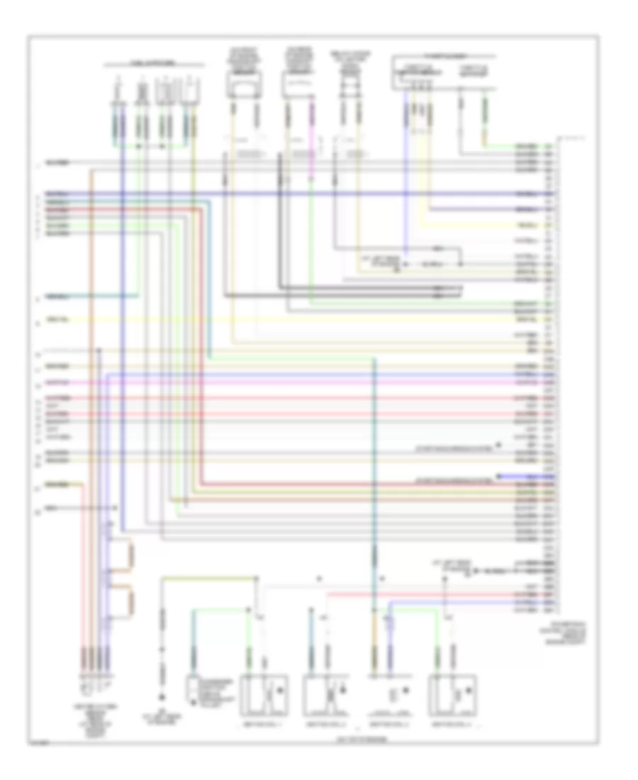
2.0L, Engine Performance Wiring Diagram, California (3 of 4) for Mazda 3 i 2005
List of elements for 2.0L, Engine Performance Wiring Diagram, California (3 of 4) for Mazda 3 i 2005:
- Egr valve (on top rear of engine)
- Engine coolant temperature sensor (on top rear of engine)
- Engine fuse 20a
- Fuel gauge sending unit
- Fuel pump
- Fuel pump relay
- Fuel pump unit (on fuel tank)
- Fuse & relay box (left rear of engine compt)
- G12 (below center console)
- G6 (at left rear of engine)
- Heated oxygen sensor (front) (right rear of engine compt)
- Heated oxygen sensor (middle) (right rear of engine compt)
- Hot in run or start
- J-01
- J-03
- J-05
- Manifold absolute pressure sensor (near front of engine compt)
- Meter fuse 10a
- Nca
- Passenger junction box (behind right side of dash)
- Purge solenoid valve (rear of engine compt)
- Red
- Variable intake-air solenoid valve (at rear of engine)
- Variable tumble shutter valve switch (at left rear of engine)
- Variable tumble solenoid valve (rear of engine)
2.0L, Engine Performance Wiring Diagram, California (4 of 4) for Mazda 3 i 2005
List of elements for 2.0L, Engine Performance Wiring Diagram, California (4 of 4) for Mazda 3 i 2005:
- (at left rear of engine) g6
- (below intake collector) knock sensor
- (on front of engine) crankshaft position sensor
- (on rear of engine) camshaft position sensor
- (on top of engine)
- 2aa
- 2ab
- 2ac
- 2ad
- 2ae
- 2af
- 2ag
- 2ah
- 2ai
- 2aj
- 2ak
- 2al
- 2am
- 2an
- 2ao
- 2ap
- 2aq
- 2ar
- 2as
- 2at
- 2au
- 2av
- 2aw
- 2ax
- 2ay
- 2az
- 2ba
- 2bb
- 2bc
- 2bd
- 2be
- 2bf
- 2bg
- 2bh
- Condenser (ignition) (above crankshaft pulley)
- Fuel injectors
- G6 (at left rear of engine)
- Heated oxygen sensor (rear) (at rear of engine compt)
- Ignition coil 1
- Ignition coil 2
- Ignition coil 3
- Ignition coil 4
- Nca
- Powertrain control module (rear of engine compt)
- Starting/charging system
- Throttle actuator
- Throttle body
- Throttle position sensor
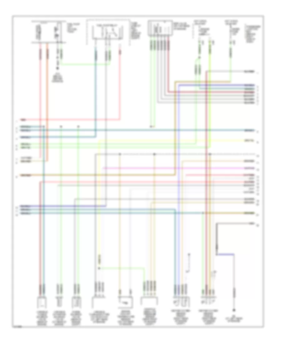
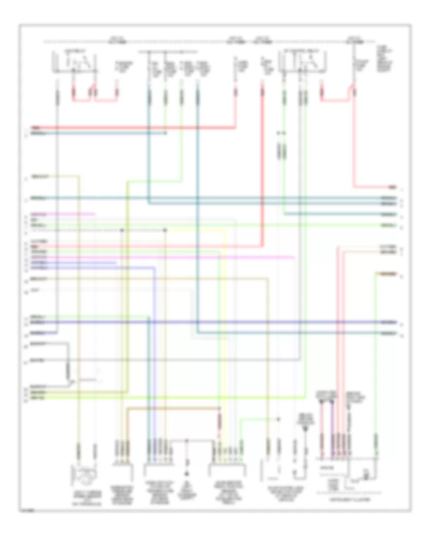
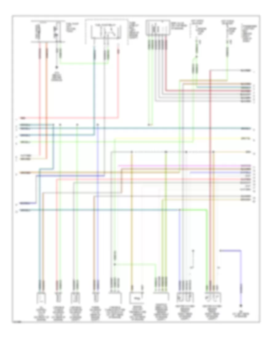
2.0L, Engine Performance Wiring Diagram, Except California (1 of 4) for Mazda 3 i 2005
List of elements for 2.0L, Engine Performance Wiring Diagram, Except California (1 of 4) for Mazda 3 i 2005:
- (a/t)
- (at transaxle range switch)
- (behind left side of dash) brake switch
- (on transaxle)
- 1aa
- 1ab
- 1ac
- 1ad
- 1ae
- 1af
- 1ag
- 1ah
- 1ai
- 1aj
- 1ak
- 1al
- 1am
- 1an
- 1ao
- 1ap
- 1aq
- 1ar
- 1as
- 1at
- 1au
- 1av
- 1aw
- 1ax
- 1ay
- 1az
- 1ba
- 1bb
- 1bc
- 1bd
- 1be
- 1bf
- 1bg
- 1bh
- A/c system
- A/t
- Clutch pedal position switch (m/t) (behind left side of dash)
- Computer data lines system
- Control valve body
- Cooling fans system
- Cruise control system
- Driver's seat)
- G11 (below
- G16
- G5 (left front of engine compt)
- G6 (at left rear of engine)
- G6 (at left rear of of engine)
- J-01
- J-05
- M/t
- Neutral switch (m/t) (near rear of engine)
- Oil pressure switch (2.3l) (on left rear side of engine)
- Passenger junction box (behind right side of dash)
- Powertrain control module (rear of engine compt)
- Pressure control solenoid
- Red
- Shift sol a
- Shift sol b
- Shift sol c
- Shift sol d
- Shift sol e
- Starting/charging system
- Transaxle fluid temp sensor
- Transaxle range switch (a/t) (on transaxle)
- Transmissions system
- Vehicle speed sensor (a/t)
- Vehicle speed sensor (m/t)
- W/ immobilizer system
- W/o immobilizer system
2.0L, Engine Performance Wiring Diagram, Except California (2 of 4) for Mazda 3 i 2005
List of elements for 2.0L, Engine Performance Wiring Diagram, Except California (2 of 4) for Mazda 3 i 2005:
- (behind right end of dash) g8
- (below center console) g12
- Accelerator pedal position sensor (at top of accelerator pedal)
- Barometric pressure sensor (near rear of engine)
- Computer data lines system
- Egi inj fuse 15a
- Eng b + fuse 10a
- Eng bar 1 fuse 10a
- Eng bar 2 fuse 10a
- Eng bar 3 fuse 10a
- Engine fuse 30a
- Et control relay
- Evap system leak detection pump (at rear of vehicle)
- F/pump fuse 15a
- Fuse & relay box (left rear of engine compt)
- G5 (left front of engine compt)
- Horn fuse 15a
- Hot at all times
- Input turbine speed sensor (a/t) (on transaxle)
- Instrument cluster
- Main relay
- Mass air flow/ intake air temperature sensor (on rear of engine
- Micro comp- uter
- Mil ind
- Red
2.0L, Engine Performance Wiring Diagram, Except California (3 of 4) for Mazda 3 i 2005
List of elements for 2.0L, Engine Performance Wiring Diagram, Except California (3 of 4) for Mazda 3 i 2005:
- Egr valve (on top rear of engine)
- Engine coolant temperature sensor (on top rear of engine)
- Engine fuse 20a
- Fuel gauge sending unit
- Fuel pump
- Fuel pump relay
- Fuel pump unit (on fuel tank)
- Fuse & relay box (left rear of engine compt)
- G12 (below center console)
- G6 (at left rear of engine)
- Heated oxygen sensor (front) (right rear of engine compt)
- Heated oxygen sensor (rear) (right rear of engine compt)
- Hot in run or start
- J-01
- J-03
- Manifold absolute pressure sensor (near front of engine compt)
- Meter fuse 10a
- Oil control valve (2.3l) (on front of engine)
- Passenger junction box (behind right side of dash)
- Purge solenoid valve (rear of engine compt)
- Red
- Variable intake-air solenoid valve (in engine compt)
- Variable tumble shutter valve switch (at left rear of engine)
- Variable tumble solenoid valve (at rear of engine)
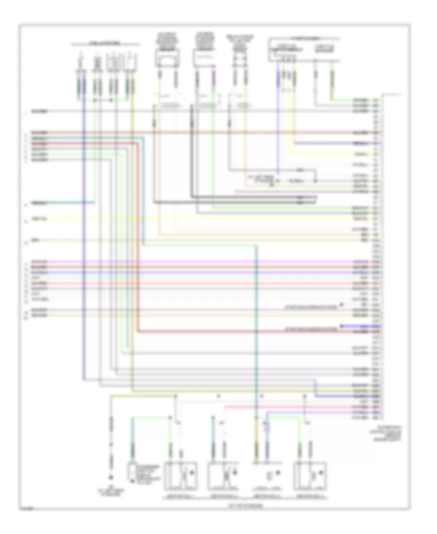
2.0L, Engine Performance Wiring Diagram, Except California (4 of 4) for Mazda 3 i 2005
List of elements for 2.0L, Engine Performance Wiring Diagram, Except California (4 of 4) for Mazda 3 i 2005:
- (at left rear of engine) g6
- (below intake collector) knock sensor
- (on front of engine) crankshaft position sensor
- (on rear of engine) camshaft position sensor
- (on top of engine)
- 2aa
- 2ab
- 2ac
- 2ad
- 2ae
- 2af
- 2ag
- 2ah
- 2ai
- 2aj
- 2ak
- 2al
- 2am
- 2an
- 2ao
- 2ap
- 2aq
- 2ar
- 2as
- 2at
- 2au
- 2av
- 2aw
- 2ax
- 2ay
- 2az
- 2ba
- 2bb
- 2bc
- 2bd
- 2be
- 2bf
- 2bg
- 2bh
- Condenser (ignition) (above crankshaft pulley)
- Fuel injectors
- G6 (at left rear of engine)
- Ignition coil 1
- Ignition coil 2
- Ignition coil 3
- Ignition coil 4
- Nca
- Powertrain control module (rear of engine compt)
- Starting/charging system
- Throttle actuator
- Throttle body
- Throttle position sensor
2.3L
2.3L, Engine Performance Wiring Diagram, California (1 of 4) for Mazda 3 i 2005
List of elements for 2.3L, Engine Performance Wiring Diagram, California (1 of 4) for Mazda 3 i 2005:
- (a/t)
- (at transaxle range switch)
- (behind left side of dash) brake switch
- (on transaxle)
- 1aa
- 1ab
- 1ac
- 1ad
- 1ae
- 1af
- 1ag
- 1ah
- 1ai
- 1aj
- 1ak
- 1al
- 1am
- 1an
- 1ao
- 1ap
- 1aq
- 1ar
- 1as
- 1at
- 1au
- 1av
- 1aw
- 1ax
- 1ay
- 1az
- 1ba
- 1bb
- 1bc
- 1bd
- 1be
- 1bf
- 1bg
- 1bh
- A/c system
- A/t
- Clutch pedal position switch (m/t) (behind left side of dash)
- Computer data lines system
- Control valve body
- Cooling fans system
- Cruise control system
- G11 (below driver's seat)
- G16
- G5 (left front of engine compt)
- G6 (at left rear of engine)
- G6 (at left rear of of engine)
- J-01
- J-05
- M/t
- Neutral switch (m/t) (near rear of engine)
- Passenger junction box (behind right side of dash)
- Powertrain control module (rear of engine compt)
- Pressure control solenoid
- Red
- Shift sol a
- Shift sol b
- Shift sol c
- Shift sol d
- Shift sol e
- Starting/charging system
- Transaxle fluid temp sensor
- Transaxle range switch (a/t) (on transaxle)
- Transmissions system
- Vehicle speed sensor (a/t)
- Vehicle speed sensor (m/t)
2.3L, Engine Performance Wiring Diagram, California (2 of 4) for Mazda 3 i 2005
List of elements for 2.3L, Engine Performance Wiring Diagram, California (2 of 4) for Mazda 3 i 2005:
- (behind right end of dash) g8
- (below center console) g12
- Accelerator pedal position sensor (at top of accelerator pedal)
- Barometric pressure sensor (near rear of engine)
- Computer data lines system
- Egi inj fuse 10a
- Eng + b fuse 10a
- Eng bar 1 fuse 10a
- Eng bar 2 fuse 10a
- Eng bar 3 fuse 10a
- Eng bar 4 fuse 10a
- Engine fuse 30a
- Et control relay
- Evap system leak detection pump (at rear of vehicle)
- F/pump fuse 15a
- Fuse & relay box (left rear of engine compt)
- G5 (left front of engine compt)
- Horn fuse 15a
- Hot at all times
- Input turbine speed sensor (a/t) (on transaxle)
- Instrument cluster
- Main relay
- Mass air flow/ intake air temperature sensor (on rear of engine
- Micro comp- uter
- Mil ind
- Red
2.3L, Engine Performance Wiring Diagram, California (3 of 4) for Mazda 3 i 2005
List of elements for 2.3L, Engine Performance Wiring Diagram, California (3 of 4) for Mazda 3 i 2005:
- Egr valve (on top rear of engine)
- Engine coolant temperature sensor (on top rear of engine)
- Engine fuse 20a
- Fuel gauge sending unit
- Fuel pump
- Fuel pump relay
- Fuel pump unit (on fuel tank)
- Fuse & relay box (left rear of engine compt)
- G12 (below center console)
- G6 (at left rear of engine)
- Heated oxygen sensor (front) (right rear of engine compt)
- Heated oxygen sensor (middle) (right rear of engine compt)
- Hot in run or start
- J-01
- J-03
- J-05
- Manifold absolute pressure sensor (near front of engine compt)
- Meter fuse 10a
- Nca
- Passenger junction box (behind right side of dash)
- Purge solenoid valve (rear of engine compt)
- Red
- Variable intake-air solenoid valve (at rear of engine)
- Variable tumble shutter valve switch (at left rear of engine)
- Variable tumble solenoid valve (rear of engine)
2.3L, Engine Performance Wiring Diagram, California (4 of 4) for Mazda 3 i 2005
List of elements for 2.3L, Engine Performance Wiring Diagram, California (4 of 4) for Mazda 3 i 2005:
- (at left rear of engine) g6
- (below intake collector) knock sensor
- (on front of engine) crankshaft position sensor
- (on rear of engine) camshaft position sensor
- (on top of engine)
- 2aa
- 2ab
- 2ac
- 2ad
- 2ae
- 2af
- 2ag
- 2ah
- 2ai
- 2aj
- 2ak
- 2al
- 2am
- 2an
- 2ao
- 2ap
- 2aq
- 2ar
- 2as
- 2at
- 2au
- 2av
- 2aw
- 2ax
- 2ay
- 2az
- 2ba
- 2bb
- 2bc
- 2bd
- 2be
- 2bf
- 2bg
- 2bh
- Condenser (ignition) (above crankshaft pulley)
- Fuel injectors
- G6 (at left rear of engine)
- Heated oxygen sensor (rear) (at rear of engine compt)
- Ignition coil 1
- Ignition coil 2
- Ignition coil 3
- Ignition coil 4
- Nca
- Powertrain control module (rear of engine compt)
- Starting/charging system
- Throttle actuator
- Throttle body
- Throttle position sensor
2.3L, Engine Performance Wiring Diagram, Except California (1 of 4) for Mazda 3 i 2005
List of elements for 2.3L, Engine Performance Wiring Diagram, Except California (1 of 4) for Mazda 3 i 2005:
- (a/t)
- (at transaxle range switch)
- (behind left side of dash) brake switch
- (on transaxle)
- 1aa
- 1ab
- 1ac
- 1ad
- 1ae
- 1af
- 1ag
- 1ah
- 1ai
- 1aj
- 1ak
- 1al
- 1am
- 1an
- 1ao
- 1ap
- 1aq
- 1ar
- 1as
- 1at
- 1au
- 1av
- 1aw
- 1ax
- 1ay
- 1az
- 1ba
- 1bb
- 1bc
- 1bd
- 1be
- 1bf
- 1bg
- 1bh
- A/c system
- A/t
- Clutch pedal position switch (m/t) (behind left side of dash)
- Computer data lines system
- Control valve body
- Cooling fans system
- Cruise control system
- Driver's seat)
- G11 (below
- G16
- G5 (left front of engine compt)
- G6 (at left rear of engine)
- G6 (at left rear of of engine)
- J-01
- J-05
- M/t
- Neutral switch (m/t) (near rear of engine)
- Oil pressure switch (2.3l) (on left rear side of engine)
- Passenger junction box (behind right side of dash)
- Powertrain control module (rear of engine compt)
- Pressure control solenoid
- Red
- Shift sol a
- Shift sol b
- Shift sol c
- Shift sol d
- Shift sol e
- Starting/charging system
- Transaxle fluid temp sensor
- Transaxle range switch (a/t) (on transaxle)
- Transmissions system
- Vehicle speed sensor (a/t)
- Vehicle speed sensor (m/t)
- W/ immobilizer system
- W/o immobilizer system
2.3L, Engine Performance Wiring Diagram, Except California (2 of 4) for Mazda 3 i 2005
List of elements for 2.3L, Engine Performance Wiring Diagram, Except California (2 of 4) for Mazda 3 i 2005:
- (behind right end of dash) g8
- (below center console) g12
- Accelerator pedal position sensor (at top of accelerator pedal)
- Barometric pressure sensor (near rear of engine)
- Computer data lines system
- Egi inj fuse 15a
- Eng b + fuse 10a
- Eng bar 1 fuse 10a
- Eng bar 2 fuse 10a
- Eng bar 3 fuse 10a
- Engine fuse 30a
- Et control relay
- Evap system leak detection pump (at rear of vehicle)
- F/pump fuse 15a
- Fuse & relay box (left rear of engine compt)
- G5 (left front of engine compt)
- Horn fuse 15a
- Hot at all times
- Input turbine speed sensor (a/t) (on transaxle)
- Instrument cluster
- Main relay
- Mass air flow/ intake air temperature sensor (on rear of engine
- Micro comp- uter
- Mil ind
- Red
2.3L, Engine Performance Wiring Diagram, Except California (3 of 4) for Mazda 3 i 2005
List of elements for 2.3L, Engine Performance Wiring Diagram, Except California (3 of 4) for Mazda 3 i 2005:
- Egr valve (on top rear of engine)
- Engine coolant temperature sensor (on top rear of engine)
- Engine fuse 20a
- Fuel gauge sending unit
- Fuel pump
- Fuel pump relay
- Fuel pump unit (on fuel tank)
- Fuse & relay box (left rear of engine compt)
- G12 (below center console)
- G6 (at left rear of engine)
- Heated oxygen sensor (front) (right rear of engine compt)
- Heated oxygen sensor (rear) (right rear of engine compt)
- Hot in run or start
- J-01
- J-03
- Manifold absolute pressure sensor (near front of engine compt)
- Meter fuse 10a
- Oil control valve (2.3l) (on front of engine)
- Passenger junction box (behind right side of dash)
- Purge solenoid valve (rear of engine compt)
- Red
- Variable intake-air solenoid valve (in engine compt)
- Variable tumble shutter valve switch (at left rear of engine)
- Variable tumble solenoid valve (at rear of engine)
2.3L, Engine Performance Wiring Diagram, Except California (4 of 4) for Mazda 3 i 2005
List of elements for 2.3L, Engine Performance Wiring Diagram, Except California (4 of 4) for Mazda 3 i 2005:
- (at left rear of engine) g6
- (below intake collector) knock sensor
- (on front of engine) crankshaft position sensor
- (on rear of engine) camshaft position sensor
- (on top of engine)
- 2aa
- 2ab
- 2ac
- 2ad
- 2ae
- 2af
- 2ag
- 2ah
- 2ai
- 2aj
- 2ak
- 2al
- 2am
- 2an
- 2ao
- 2ap
- 2aq
- 2ar
- 2as
- 2at
- 2au
- 2av
- 2aw
- 2ax
- 2ay
- 2az
- 2ba
- 2bb
- 2bc
- 2bd
- 2be
- 2bf
- 2bg
- 2bh
- Condenser (ignition) (above crankshaft pulley)
- Fuel injectors
- G6 (at left rear of engine)
- Ignition coil 1
- Ignition coil 2
- Ignition coil 3
- Ignition coil 4
- Nca
- Powertrain control module (rear of engine compt)
- Starting/charging system
- Throttle actuator
- Throttle body
- Throttle position sensor
EXTERIOR LIGHTS
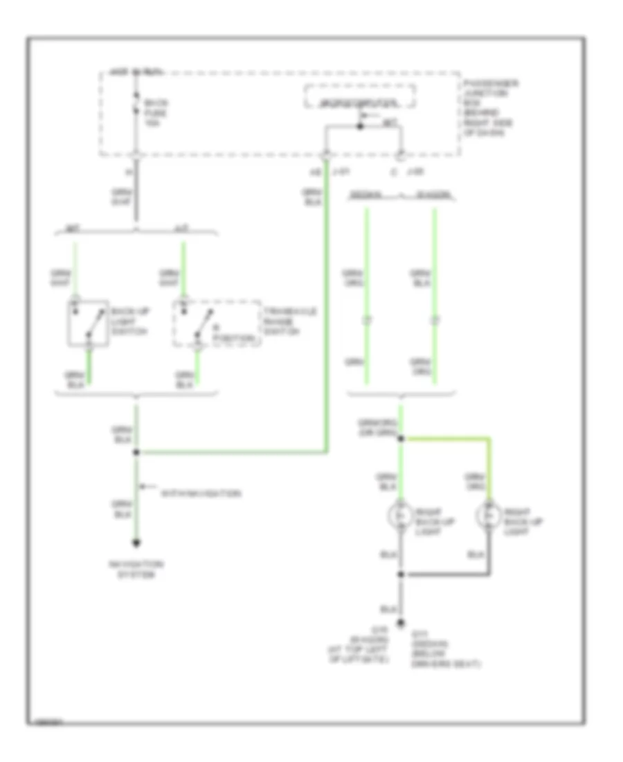
Back-up Lamps Wiring Diagram for Mazda 3 i 2005
List of elements for Back-up Lamps Wiring Diagram for Mazda 3 i 2005:
- A/t
- Back fuse 10a
- Back-up light switch
- G11 (sedan) (below drivers seat)
- G15 (wagon) (at top left of liftgate)
- Hot in run
- J-01 ae
- J-05 c
- M/t
- Microcomputer
- Navigation system
- Passenger junction box (behind right side of dash)
- R position
- Right back-up light
- Sedan
- Transaxle range switch
- Wagon
- With navigation
Exterior Lamps Wiring Diagram for Mazda 3 i 2005
List of elements for Exterior Lamps Wiring Diagram for Mazda 3 i 2005:
- 0140-101
- 1au
- Auto
- Brake switch (behind left side of dash)
- Btn fuse 40a
- Condenser
- Cpu pwr fuse 10a
- Fuse & relay block (left rear of engine compt)
- G1 (behind left headlight)
- G11 (sedan) (below driver's seat)
- G11 (sedan) (below drivers seat)
- G12 (wagon) (below center console)
- G13 (wagon) (top left side of liftgate)
- G14 (sedan) (behind rear seat)
- G15 (top left of liftgate)
- G3 (behind right headlight)
- G8 (behind right end of dash)
- Hazard fuse 15a
- Hazard warning switch
- Head
- Head- lights system
- Headlight switch
- High mount brake light
- Horn fuse 15a
- Hot at all times
- Interior lights system
- J-01
- J-01 ak
- J-01 k
- J-01 l
- J-03
- J-04
- J-05
- J-05 ak
- J-05 as
- Left brake light
- Left front side turn light
- Left front turn light
- Left parking light
- Left rear turn light
- Left taillight
- License plate light
- Microcomputer
- Off
- Passenger junction box (behind right side of dash)
- Pcm (rear of engine compartment)
- Red
- Right brake light
- Right front side turn light
- Right front turn light
- Right parking light
- Right rear turn light
- Right taillight
- Sedan
- Shift interlock system
- Tail l fuse 7.5a
- Tail r fuse 7.5a
- Tns
- Tns relay
- Turn switch
- Wagon
GROUND DISTRIBUTION
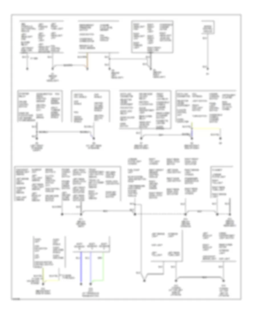
Ground Distribution Wiring Diagram for Mazda 3 i 2005
List of elements for Ground Distribution Wiring Diagram for Mazda 3 i 2005:
- (behind left headlight)
- (wagon) (at top left of liftgate)
- Abs hydraulic unit/control module
- Acceleration pedal position sensor
- Ashtray illumination
- Audio amplifier
- Audio amplifier shield
- Audio unit
- Audio unit shield
- Blower relay
- Brake fluid level sensor
- Brake switch 2
- Car navigation control switch shield
- Car navigation unit
- Cargo compartment light switch
- Cigarette lighter
- Ckp shield
- Climate control unit
- Clock spring
- Clutch pedal position switch (m/t)
- Cmp shield
- Coil antenna
- Cruise control switch
- Data link connector
- Door key cylinder switch
- Door lock relay
- Door lock- link switch
- Door unlock relay
- Driver side buckle switch
- Driver side unlock relay
- Ehpas control module
- Evap system leak detection pump
- Fan control module
- Fan switch
- Filament
- Front fog light switch
- Front wiper low relay
- Fuel pump unit
- G1 (behind left headlight)
- G10 (behind right side of dash)
- G11 (below driver's seat)
- G12 (below center console)
- G13 (wagon) (at top left side of liftgate)
- G14 (sedan) (behind rear seat)
- G15
- G16 (a/t) (at transaxle range switch)
- G3 (behind right headlight)
- G5 (left front of engine compt)
- G6 (at left rear of engine)
- G7 (behind left side of dash)
- G8 (behind right end of dash)
- Glove compartment light
- Hazard warning switch
- Headlight leveling switch
- Heated oxygen sensor shield
- High-mount brake light
- High-mount brake light (sedan)
- Hood switch
- Horn switch
- Ignition coil shield
- Input/ turbine speed sensor shield
- Instrument cluster
- Interior light
- Interior light (sedan)
- Keyless control module
- Knock sensor shield
- Lcd unit
- Left back-up light
- Left back-up light (sedan)
- Left brake light
- Left brake light (sedan)
- Left door lock switch
- Left front door latch switch
- Left front door lock actuator
- Left front fog light
- Left front side turn light
- Left front turn light
- Left headlight high
- Left headlight leveling actuator
- Left headlight low
- Left heated outer mirror
- Left parking light
- Left rear door latch switch
- Left rear door lock actuator
- Left rear turn light
- Left rear turn light (sedan)
- Left taillight
- Left taillight (sedan)
- License plate light
- License plate light (wagon)
- Light switch
- Map light
- Map light (sedan)
- Mass air flow/intake air temper- ature sensor
- Micro- computer
- Module
- Neutral switch (m/t)
- Panel light control switch
- Passenger side buckle switch
- Pcm
- Power outer mirror switch
- Power window main switch
- Rain sensor (w/ auto wiper)
- Rear wiper & washer switch
- Rear wiper motor
- Rear wiper relay
- Refrigerant pressure switch
- Right back-up light
- Right back-up light (sedan)
- Right brake light
- Right brake light (wagon)
- Right door lock switch
- Right front door latch switch
- Right front door lock actuator
- Right front fog light
- Right front side turn light
- Right front turn light
- Right headlight high
- Right headlight leveling actuator
- Right headlight low
- Right heated outer mirror
- Right parking light
- Right rear door latch switch
- Right rear door lock actuator
- Right rear turn light
- Right rear turn light (wagon)
- Right taillight
- Right taillight (wagon)
- Sas control module
- Seat weight sensor control module
- Selector lever component
- Shift solenoid a
- Shift solenoid b
- Shift solenoid c
- Starter relay
- Sunroof unit
- Tire pressure monitoring system control
- Trunk compartment light switch (sedan)
- Trunk lid key cylinder switch (sedan)
- Turn switch
- Vehicle speed sensor
- W/ abs
- W/ bose type audio
- W/ car navigation system
- Washer fluid level sensor
- Windshield washer motor
- Windshield wiper & washer switch
- Windshield wiper motor
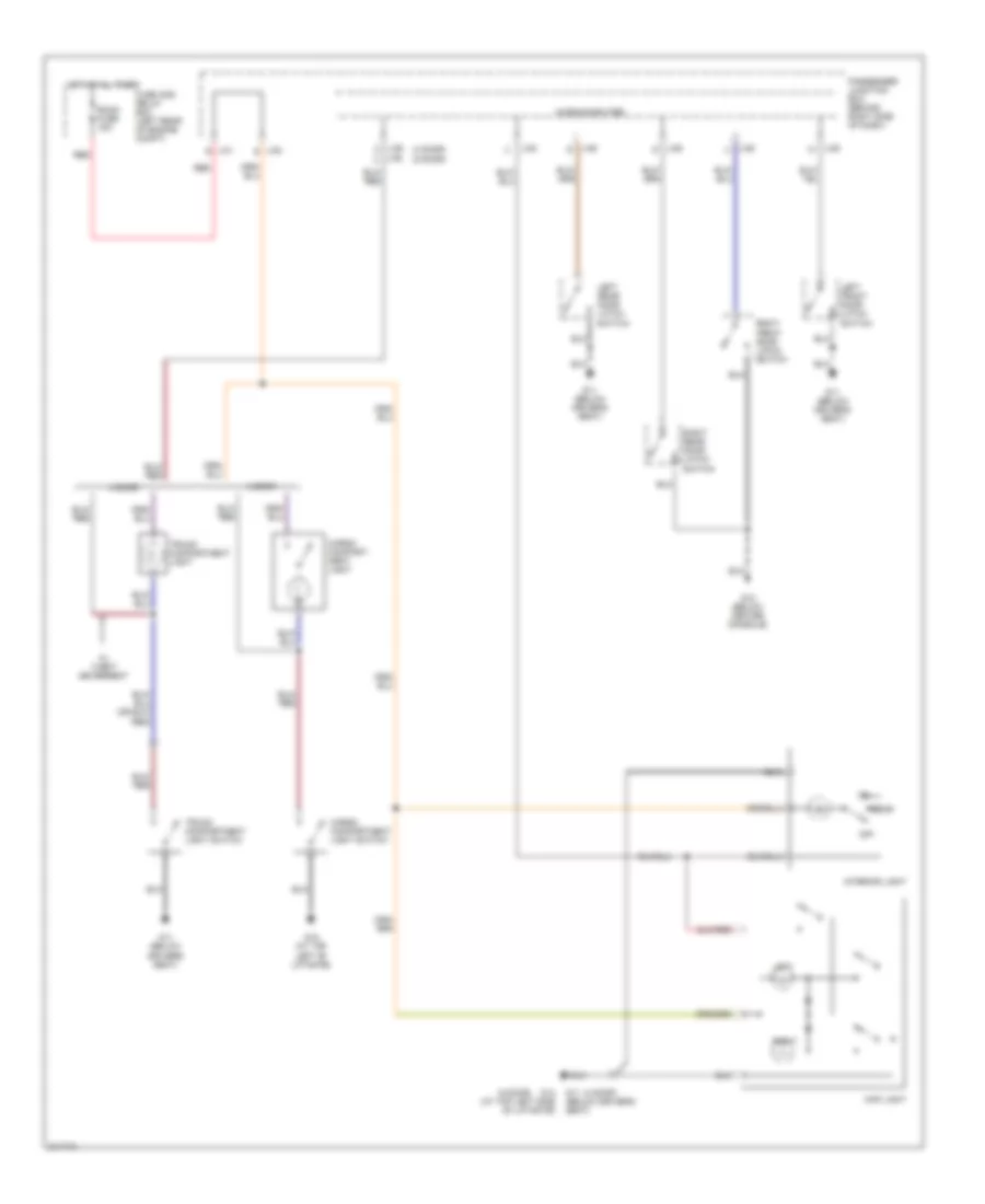
HEADLIGHTS
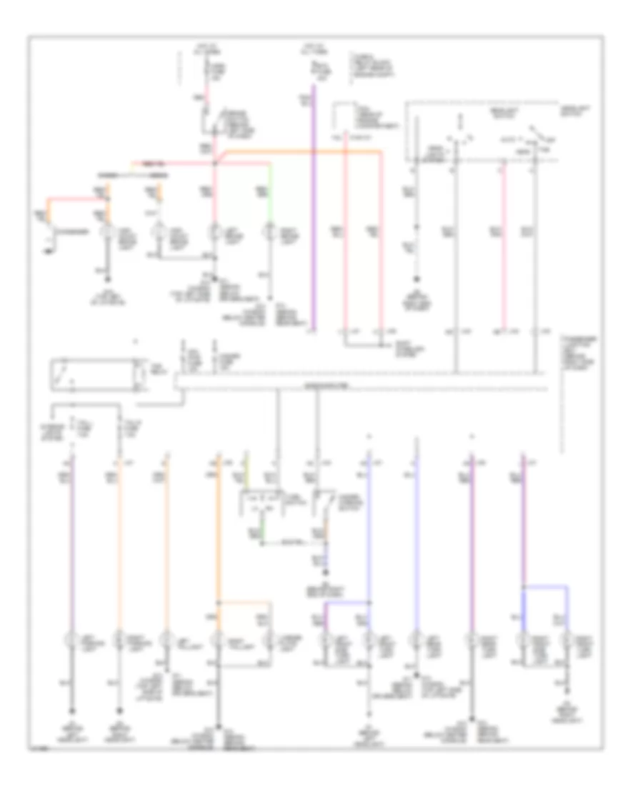
Headlights Wiring Diagram, with DRL for Mazda 3 i 2005
List of elements for Headlights Wiring Diagram, with DRL for Mazda 3 i 2005:
- Acc
- Auto
- Beam switch
- Flash- to- pass
- Fog fuse 15a
- Front fog light relay (in fuse & relay block)
- Front fog light switch
- Fuse & relay block (left rear of engine compt)
- G1 (behind left headlight)
- G3 (behind right headlight)
- G8 (behind right end of dash)
- Head
- Head fuse 40a
- Head high l fuse 10a
- Head high r fuse 10a
- Head low l fuse 10a
- Head low r fuse 10a
- Headlight high relay
- Headlight low relay
- Headlight switch
- Hot at all times
- Ignition switch
- J-01
- J-02
- J-03
- J-03 as
- J-03 i
- J-04 ae
- J-04 l
- Left front fog light
- Left high headlight
- Left low headlight
- Light switch
- Lock
- Microcomputer
- Off
- Passenger junction box (behind right side of dash)
- Red
- Right front fog light
- Right high headlight
- Right low headlight
- Run
- Start
- Tns
- With auto light system
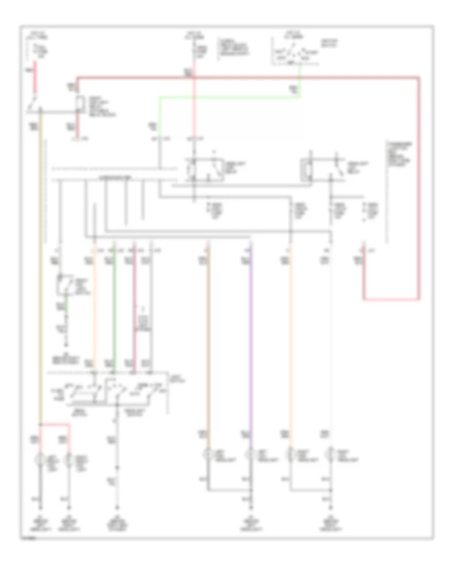
Headlights Wiring Diagram, without DRL for Mazda 3 i 2005
List of elements for Headlights Wiring Diagram, without DRL for Mazda 3 i 2005:
- Acc
- Auto
- Beam switch
- Flash- to- pass
- Fog fuse 15a
- Front fog light relay (in fuse & relay block)
- Front fog light switch
- Fuse & relay block (left rear of engine compt)
- G1 (behind left headlight)
- G3 (behind right headlight)
- G8 (behind right end of dash)
- Halogen type
- Head
- Head fuse 40a
- Head high l fuse 10a
- Head high r fuse 10a
- Head low l fuse 10a
- Head low r fuse 10a
- Headlight high relay
- Headlight low relay
- Headlight switch
- Hid type
- Hot at all times
- Ignition switch
- J-01
- J-01 c
- J-02
- J-03
- J-03 as
- J-03 i
- J-04 ae
- J-04 l
- Left front fog light
- Left hid control unit
- Left high head- light
- Left low head- light
- Left low headlight
- Light switch
- Lock
- Microcomputer
- Off
- Passenger junction box (behind right side of dash)
- Red
- Right front fog light
- Right hid control unit
- Right high head- light
- Right low head- light
- Right low headlight
- Run
- Start
- Tns
- With auto light system
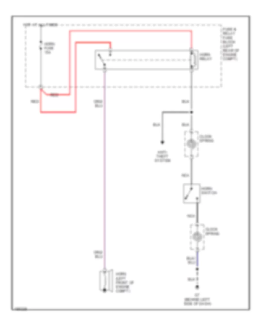
HORN
Horn Wiring Diagram for Mazda 3 i 2005
List of elements for Horn Wiring Diagram for Mazda 3 i 2005:
- Anti- theft system
- Clock spring
- Fuse & relay fuse block (left rear of engine compt)
- G7 (behind left side of dash)
- Horn (left front of engine compt)
- Horn fuse 15a
- Horn relay
- Horn switch
- Hot at all times
- Nca
- Red
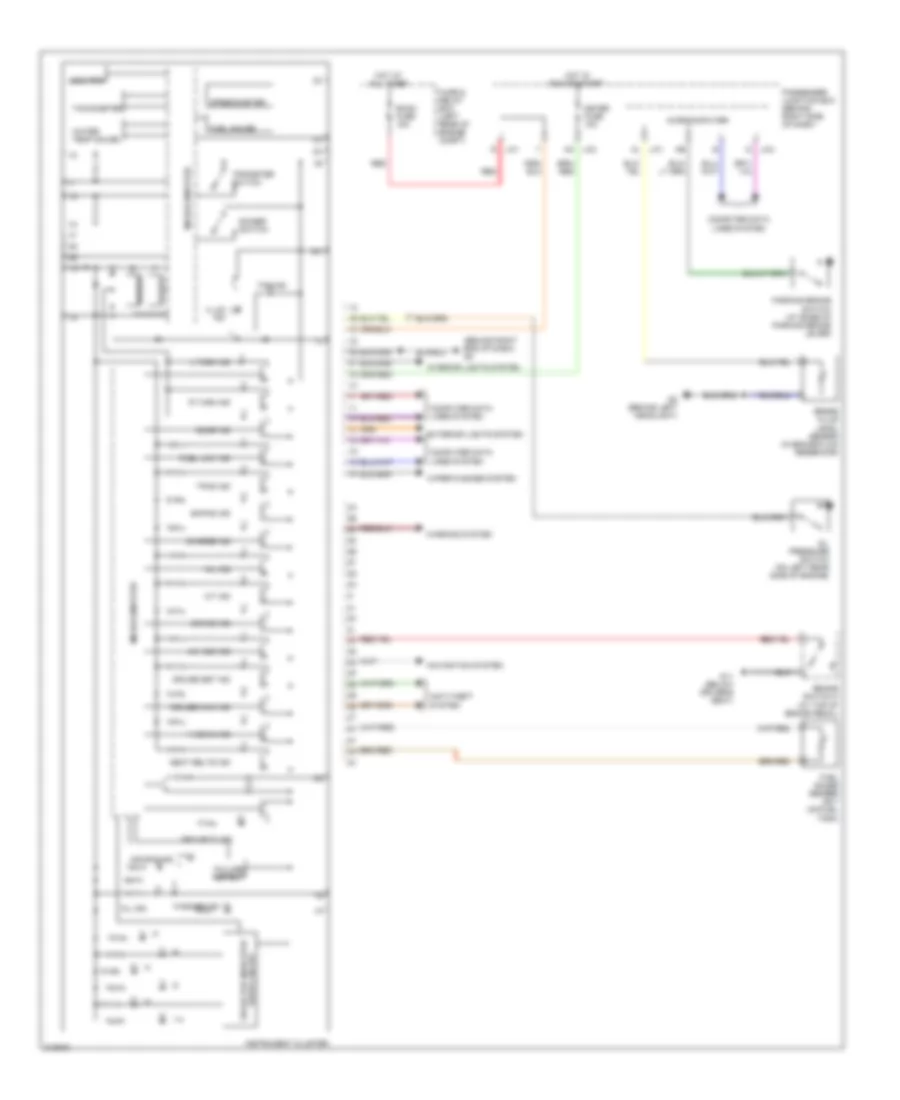
INSTRUMENT CLUSTER
Instrument Cluster Wiring Diagram for Mazda 3 i 2005
List of elements for Instrument Cluster Wiring Diagram for Mazda 3 i 2005:
- (behind right end of dash) g8
- 1-4
- 4w abs ind
- A/t ind
- Ac j-03
- Air bag ind
- Anti-theft system
- Brake fluid level sensor (in brake fluid reservoir)
- Brake ind
- Brake switch 2 (at top of brake pedal)
- Buzzer
- Charge ind
- Computer data lines system
- Cruise main ind
- Cruise set ind
- D j-04
- Dimmer switch
- Door ind
- Drive circuit selector indicator
- Ehpas ind
- Exterior lights system
- Failure detect
- Fuel gauge
- Fuel gauge sender unit (on fuel tank)
- Fuel low ind
- Fuse & relay box (left rear of engine compt)
- G11 (below driver's seat)
- G2 (behind left headlight)
- Hi beam ind
- Hot at all times
- Hot in run or start
- Illum ind
- Instrument cluster
- Interior lights system
- J-01 al
- J-01 r
- L turn ind
- Meter fuse 10a
- Microcomputer
- Mil ind
- Navigation system
- Odo/trip
- Oil ind
- Oil pressure switch (on left rear side of engine)
- Parking brake switch (at base of parking brake lever)
- Passenger junction box (behind right side of dash)
- R turn ind
- Red
- Room fuse 15a
- Seat belts ind
- Security ind
- Speedometer
- Tachometer
- Tns ind
- Tpms ind
- Tripmeter switch
- Warning system
- Washer ind
- Water temp gauge
- Wiper/washer system
INTERIOR LIGHTS
Courtesy Lamp Wiring Diagram for Mazda 3 i 2005
List of elements for Courtesy Lamp Wiring Diagram for Mazda 3 i 2005:
- (4 door)
- (5 door)
- 4 door
- 5 door
- Cargo compart- ment light
- Cargo compartment light switch
- Door
- Fuse and relay box (left rear of engine compt)
- G11 (below driver's seat)
- G12 (below center console)
- G13 (at top left side of liftgate)
- G15 (at top left of liftgate)
- Hot at all times
- Interior light
- J-01 r
- J-05
- J-05 s
- J-06 q
- J-06 s
- J-06 u
- J-06 w
- J-06 x
- J-06 z
- Left
- Left front door latch switch
- Left rear door latch switch
- Map light
- Microcomputer
- Off
- Passenger junction box (behind right side of dash)
- Red
- Right
- Right front door latch switch
- Right rear door latch switch
- Room fuse 15a
- Trunk compartment light
- Trunk compartment light switch
- W/ theft deterrent
Instrument Illumination Wiring Diagram for Mazda 3 i 2005
List of elements for Instrument Illumination Wiring Diagram for Mazda 3 i 2005:
- (center of dash)
- 0922-202
- 0922-203
- Ashtray illumination
- Audio control switch illumination
- Audio unit
- Auto
- Beam switch
- Btn fuse 40a
- Cigarette lighter illumination
- Climate control unit
- Clock spring (below steering wheel)
- Cruise control switch illumination
- Flash- to- pass
- Fuse & relay box (left rear of engine compt)
- G7 (behind left side of dash)
- G8 (behind right end of dash)
- Glove compartment light
- Hazard warning switch illumination
- Head
- Headlight leveling switch illumination (w/ headlight manual leveling system)
- Headlight switch
- Headlights system
- Hot at all times
- Ignition key illumination
- Illum
- Illumi 7.5a
- Instrument cluster
- J-01
- J-01 f
- J-03
- J-04
- J/c c17 (behind center of dash)
- J/c c18 (behind center of dash)
- Lcd unit
- Micro- computer
- Microcomputer
- Navigation system
- Nca
- Off
- Panel light control switch
- Passenger junction box (behind right side of dash)
- Red
- Room fuse 15a
- Selector lever component illumination (a/t)
- Tns
- Tns relay
NAVIGATION
Navigation Wiring Diagram for Mazda 3 i 2005
List of elements for Navigation Wiring Diagram for Mazda 3 i 2005:
- (behind right side of dash) g10
- (w/
- (w/ bose audio)
- A/t
- Back fuse 10a
- Back-up light switch (on transaxle)
- Car-navigation control switch
- Car-navigation unit (behind right side of dash)
- Exterior lights system
- Fuse & relay box (left rear of engine compt)
- G10 (behind right side of dash)
- Hot at all times
- Hot in acc or run
- Hot in run
- Information display
- Instrument cluster
- Interior lights system
- J-01 h
- J-01 r
- J-03 aa
- Lcd unit (center of dash)
- M/t
- Nca
- Passenger junction box (behind right side of dash)
- R position
- Radio fuse 7.5a
- Red
- Room fuse 15a
- Sound systems
- Standard audio)
- Transaxle range switch (on transaxle)
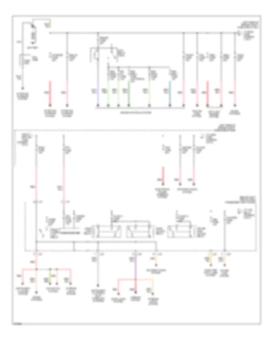
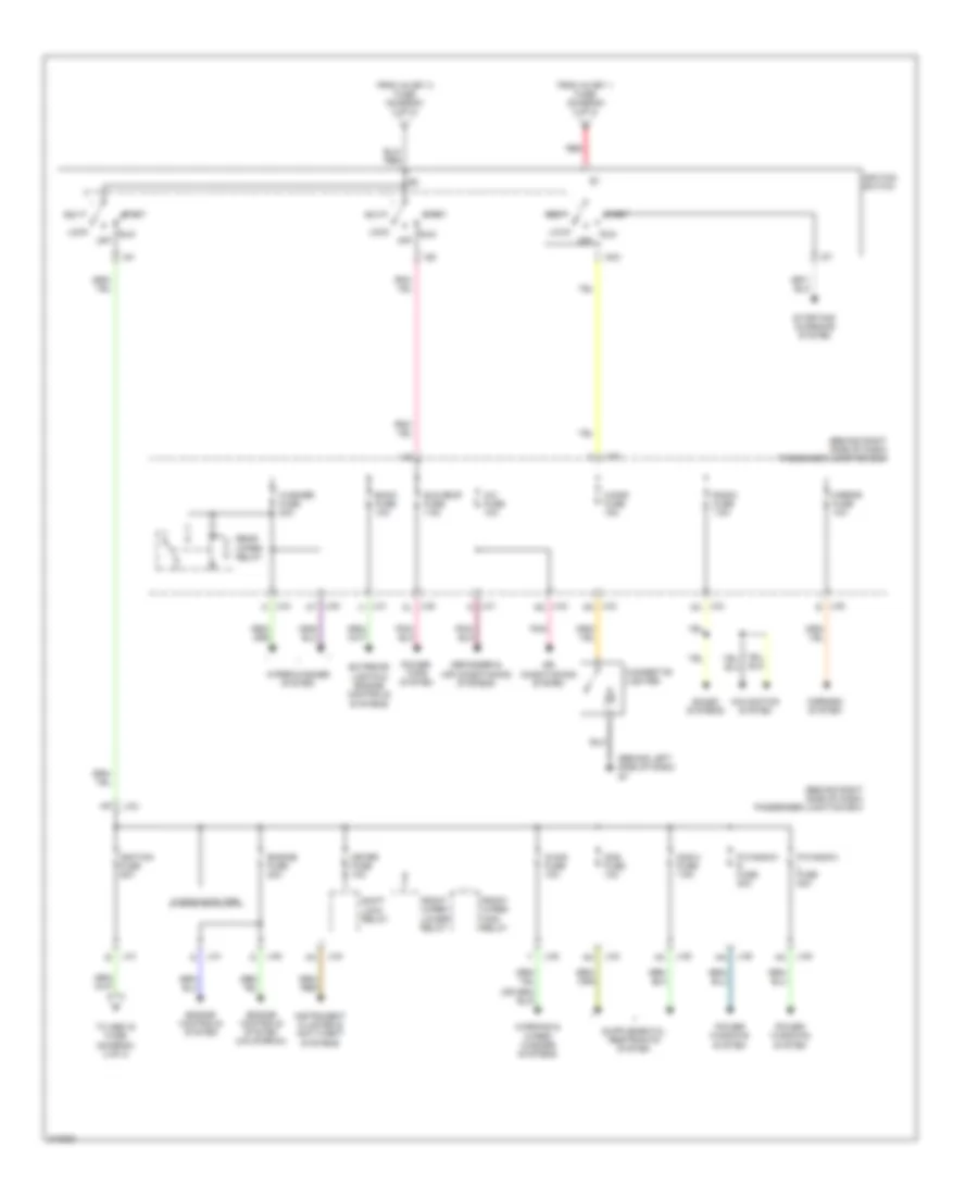
POWER DISTRIBUTION
Power Distribution Wiring Diagram (1 of 3) for Mazda 3 i 2005
List of elements for Power Distribution Wiring Diagram (1 of 3) for Mazda 3 i 2005:
- (behind right side of dash) passenger junction box
- (left rear of engine compt) fuse & relay box
- A/c mag fuse 10a
- Abs 1 fuse 30a
- Abs 2 fuse 20a
- Air conditioning system
- Anti-lock brakes system
- Audio fuse 30a
- Battery
- Btn fuse 40a
- Computer data lines system
- Cooling fans system
- Cpu pwr fuse 10a
- D/lock 1 fuse 25a
- D/lock 2 fuse 15a
- Door lock relay
- Door locks system
- Door unlock relay
- Driver side unlock relay
- Egi inj fuse 10a
- Electronic power steering system
- Eng +b fuse 10a
- Eng bar 1 fuse 10a
- Eng bar 2 fuse 10a
- Eng bar 3 fuse 10a
- Eng bar 4 fuse (california) 10a
- Engine controls system
- Engine fuse 30a
- F/pump fuse 15a
- Fan fuse 40a
- From abs 2 a fuse (diagram 1 of 3)
- Front wiper low relay
- Fuse 150a
- Hazard fuse 15a
- Heater fuse 40a
- Instrument cluster & shift interlock systems
- Instrument cluster system
- Interior lights system
- J-01
- J-03
- J-05
- Main fuse
- Main relay (main)
- Microcomputer
- Navigation system
- Nca
- Obd fuse 10a
- P/st fuse 80a
- Pnk/ red
- Power tops system
- Red
- Room fuse 15a
- Sound systems
- Starter fuse 20a
- Starting/ charging system
- Sun roof fuse 20a
- To horn fuse (diagram 2 of 3)
- To room fuse (diagram 1 of 3)
- To tns relay (diagram 2 of 3)
- Warning system
- Wiper fuse 20a
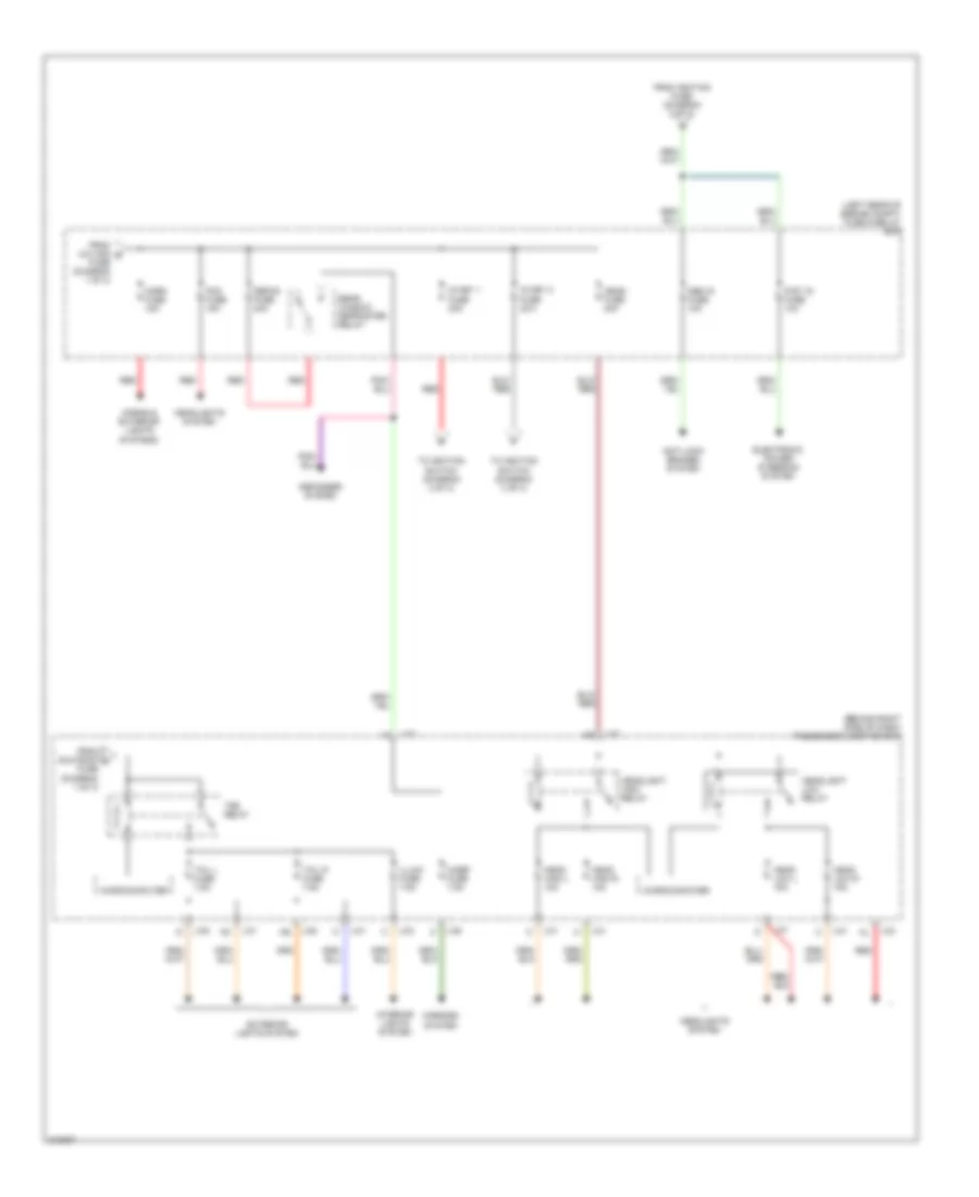
Power Distribution Wiring Diagram (2 of 3) for Mazda 3 i 2005
List of elements for Power Distribution Wiring Diagram (2 of 3) for Mazda 3 i 2005:
- (behind right side of dash) passenger junction box
- (left rear of engine compt) fuse & relay box
- Abs ig fuse 10a
- Anti-lock brakes system
- Defog fuse 40a
- Defogger system
- Electronic power steering system
- Exterior lights system
- Fog fuse 15a
- From a/c mag b fuse (diagram 1 of 3)
- From ignition fuse (diagram 3 of 3)
- From sun roof c fuse (diagram 1 of 3)
- Head fuse 40a
- Head high l 10a
- Head high r 10a
- Head low l 15a
- Head low r 15a
- Headlight high relay
- Headlight low relay
- Headlights system
- Horn fuse 15a
- Horns & exterior lights systems
- Ig key 1 fuse 30a
- Ig key 2 fuse 30a
- Illumi fuse 7.5a
- Interior lights system
- J-01
- J-03
- J-05
- M/def fuse 7.5a
- Microcomputer
- Mirrors system
- P/st ig fuse 10a
- Rear window defroster relay
- Red
- Tail l fuse 7.5a
- Tail r fuse 7.5a
- Tns relay
- To ignition switch (diagram 3 of 3)
Power Distribution Wiring Diagram (3 of 3) for Mazda 3 i 2005
List of elements for Power Distribution Wiring Diagram (3 of 3) for Mazda 3 i 2005:
- (behind left side of dash) g7
- (behind right side of dash) passenger junction box
- A/c fuse 10a
- Acc
- Air conditioning system
- Back fuse 10a
- Cigar fuse 15a
- Cigarette lighter
- Defogger & air conditioning systems
- Engine controls system
- Engine controls system (california)
- Engine fuse 20a
- Exterior lights & engine controls systems
- From ig key 1 fuse (diagram 2 of 3)
- From ig key 2 fuse (diagram 2 of 3)
- Front wiper high relay
- Front wiper lower relay
- Ig sig fuse 10a
- Ig1
- Ig2
- Ignition fuse 20a
- Ignition switch
- Instrument cluster & anti-theft systems
- J-01
- J-01 g
- J-01 h
- J-03
- J-03 aa
- J-03 ad
- J-03 an
- J-03 n
- J-05
- J-05 al
- J-05 at
- J-05 e
- Lock
- Meter fuse 10a
- Microcomputer
- Mirror fuse 10a
- Mirrors system
- Navigation system
- Off
- P/window l fuse 30a
- P/window r fuse 30a
- Pnk
- Power tops system
- Power windows system
- Radio fuse 7.5a
- Rear wiper relay
- Red
- Run
- Sas 2 fuse 7.5a
- Sas fuse 10a
- Shift lock relay
- Sound systems
- Start
- Starting/ charging system
- Sun roof fuse 7.5a
- To abs ig fuse (diagram 2 of 3)
- Warning & wiper/ washer systems
- Washer fuse 20a
- Wiper/washer system
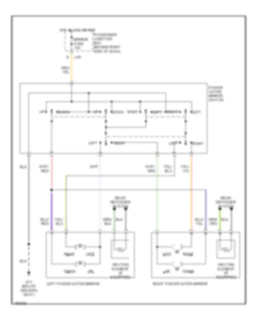
POWER MIRRORS
Power Mirrors Wiring Diagram for Mazda 3 i 2005
List of elements for Power Mirrors Wiring Diagram for Mazda 3 i 2005:
- Down
- E j-05
- G11 (below driver's seat)
- Heating element (if equipped)
- Hot in acc or run
- Left
- Left power outer mirror
- Mirror fuse 10a
- Passenger junction box (behind right side of dash)
- Power outer mirror switch
- Rear defogger system
- Right
- Right power outer mirror
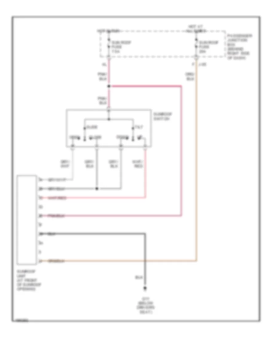
POWER TOP/SUNROOF
Power Top/Sunroof Wiring Diagram for Mazda 3 i 2005
List of elements for Power Top/Sunroof Wiring Diagram for Mazda 3 i 2005:
- Close
- Down
- G11 (below driver's seat)
- Hot at all times
- Hot in run
- J-05 f
- Open
- Passenger junction box (behind right side of dash)
- Slide
- Sun roof fuse 20a
- Sun roof fuse 7.5a
- Sunroof switch
- Sunroof unit (at front of sunroof opening)
- Tilt
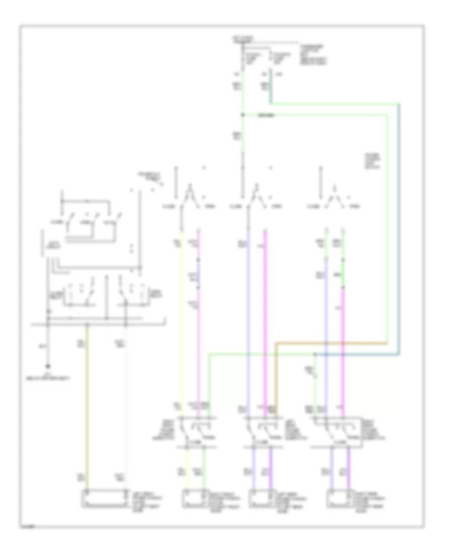
POWER WINDOWS
Power Windows Wiring Diagram for Mazda 3 i 2005
List of elements for Power Windows Wiring Diagram for Mazda 3 i 2005:
- Auto
- Auto circuit
- Close
- Close relay
- G11 (below driver's seat)
- Hot in run or start
- J-05
- Left front power window motor (in left front door)
- Left rear power window motor (in left rear door)
- Left rear power window subswitch
- Open
- Open relay
- P/wind l fuse 30a
- P/wind r fuse 30a
- Passenger junction box (behind right side of dash)
- Power window main switch
- Power-cut switch
- Right front power window motor (in right front door)
- Right front power window subswitch
- Right rear power window motor (in right rear door)
- Right rear power window subswitch
RADIO
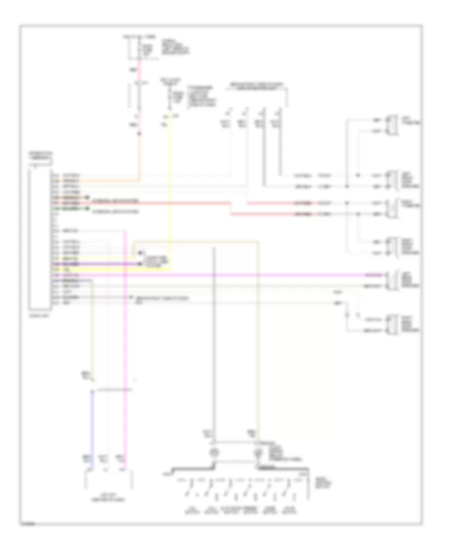
Radio Wiring Diagram, with Base with Navigation for Mazda 3 i 2005
List of elements for Radio Wiring Diagram, with Base with Navigation for Mazda 3 i 2005:
- (behind right side of dash) car navigation unit
- (behind right side of dash) g10
- (center of dash)
- 0922-202
- 0922-203
- Audio control switch
- Audio unit
- Auto scan switch
- Clock spring (below steering wheel)
- Computer data lines system
- Fuse & relay box (left rear of engine compt)
- Hot at all times
- Hot in acc or run
- Information display
- Interior lights system
- J-01 r
- J-03 aa
- Lcd unit
- Left front door speaker
- Left rear door speaker
- Left tweeter
- Mode switch
- Mute switch
- Nca
- Passenger junction box (pjb) (behind right side of dash)
- Preset switch
- Radio fuse 7.5a
- Red
- Right front door speaker
- Right rear door speaker
- Right tweeter
- Room fuse 15a
- Vol+ switch
- Vol- switch
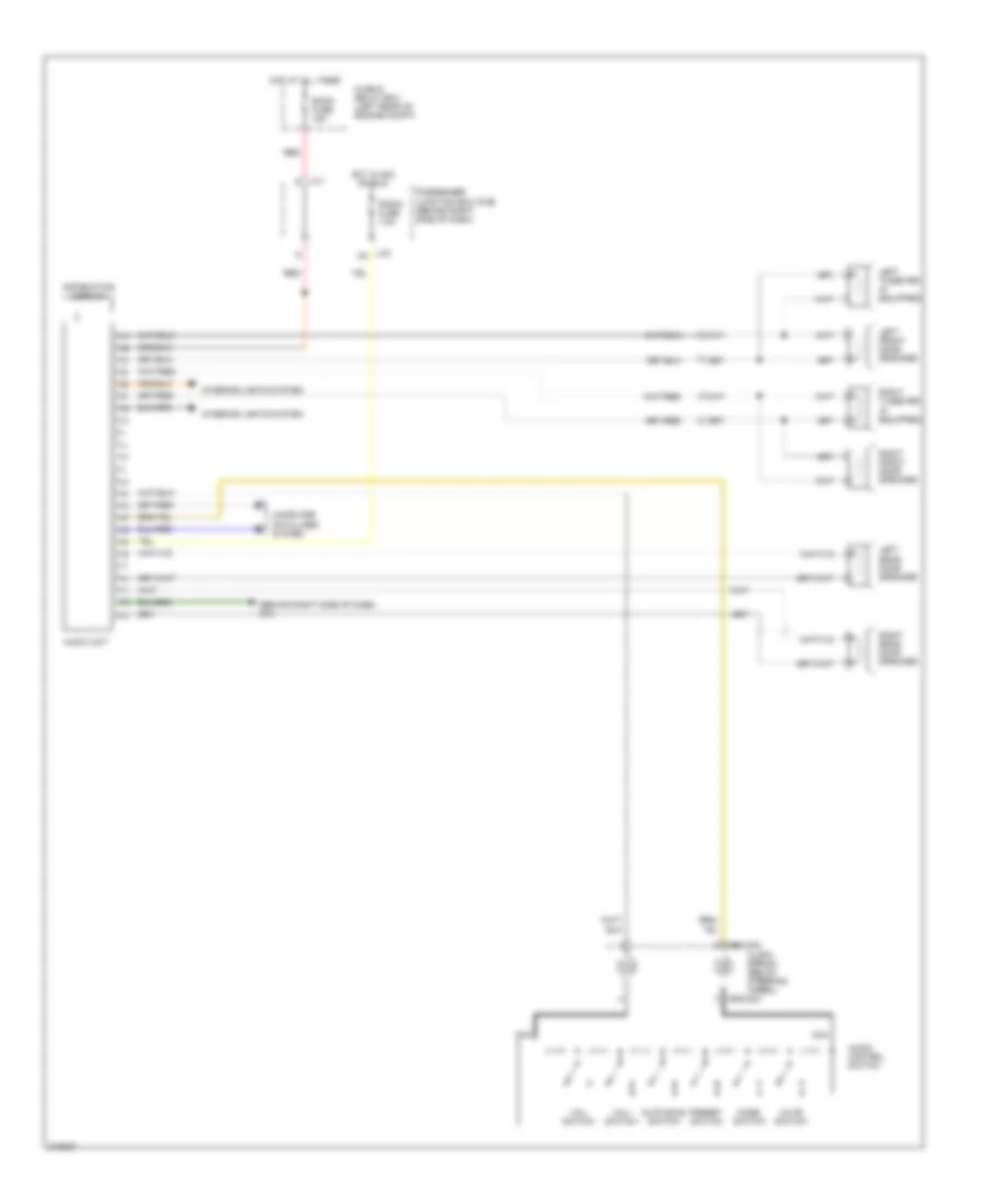
Radio Wiring Diagram, with Base without Navigation for Mazda 3 i 2005
List of elements for Radio Wiring Diagram, with Base without Navigation for Mazda 3 i 2005:
- (behind right side of dash)
- 0922-202
- 0922-203
- Audio control switch
- Audio unit
- Auto scan switch
- Clock spring (below steering wheel)
- Computer data lines system
- Fuse & relay box (left rear of engine compt)
- G10
- Hot at all times
- Hot in acc or run
- Information display
- Interior lights system
- J-01 r
- J-03 aa
- Left front door speaker
- Left rear door speaker
- Left tweeter (if equipped)
- Mode switch
- Mute switch
- Nca
- Passenger junction box (pjb) (behind right side of dash)
- Preset switch
- Radio fuse 7.5a
- Red
- Right front door speaker
- Right rear door speaker
- Right tweeter (if equipped)
- Room fuse 15a
- Vol+ switch
- Vol- switch
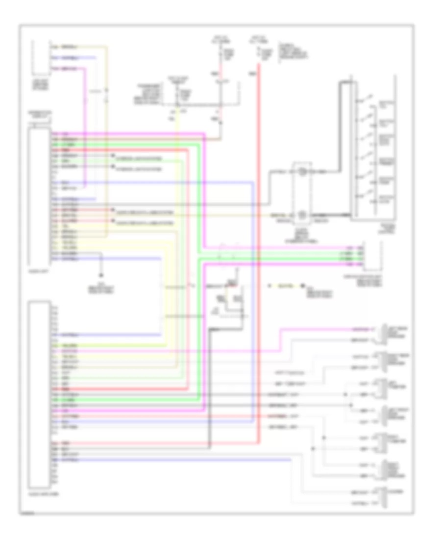
Radio Wiring Diagram, with Bose with Navigation for Mazda 3 i 2005
List of elements for Radio Wiring Diagram, with Bose with Navigation for Mazda 3 i 2005:
- 0922-202
- 0922-203
- Audio amplifier
- Audio fuse 30a
- Audio unit
- Car navigation unit (behind right side of dash)
- Clock spring (below steering wheel)
- Computer data lines system
- Fuse & relay box (left rear of engine compt)
- G10 (behind right side of dash)
- Hot at all times
- Hot in acc or run
- Information display
- Interior lights system
- J-01 r
- J-03 aa
- J/c c-24
- Lcd unit (center of dash)
- Left front door speaker
- Left rear door speaker
- Left tweeter
- Nca
- Passenger junction box (pjb) (behind right side of dash)
- Radio fuse 7.5a
- Red
- Right front door speaker
- Right rear door speaker
- Right tweeter
- Room fuse 15a
- Switch audio control
- Switch mode
- Switch mute
- Switch preset
- Switch scan auto
- Switch vol+
- Switch vol-
- Woofer
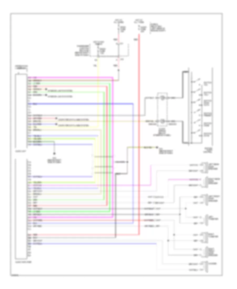
Radio Wiring Diagram, with Bose without Navigation for Mazda 3 i 2005
List of elements for Radio Wiring Diagram, with Bose without Navigation for Mazda 3 i 2005:
- 0922-202
- 0922-203
- Audio amplifier
- Audio fuse 30a
- Audio unit
- Clock spring (below steering wheel)
- Computer data lines system
- Fuse & relay box (left rear of engine compt)
- G10 (behind right side of dash)
- Hot at all times
- Hot in acc or run
- Information display
- Interior lights system
- J-01 r
- J-03
- Left front door speaker
- Left rear door speaker
- Left tweeter
- Nca
- Passenger junction box (pjb) (behind right side of dash)
- Radio fuse 7.5a
- Red
- Right front door speaker
- Right rear door speaker
- Right tweeter
- Room fuse 15a
- Switch audio control
- Switch mode
- Switch mute
- Switch preset
- Switch scan auto
- Switch vol+
- Switch vol-
- Woofer
SHIFT INTERLOCK
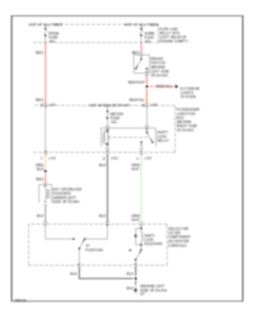
Shift Interlock Wiring Diagram for Mazda 3 i 2005
List of elements for Shift Interlock Wiring Diagram for Mazda 3 i 2005:
- "p" position
- (behind left side of dash) g7
- Brake switch (behind left side of dash)
- Exterior lights system
- Fuse and relay box (left rear of engine compt)
- Horn fuse 15a
- Hot at all times
- Hot in run or start
- J-01
- J-03
- J-05
- Key interlock solenoid (under left side of dash)
- Meter fuse 10a
- Passenger junction box (behind right side of dash)
- Red
- Room fuse 15a
- Selector lever component (in center console)
- Shift- lock relay
- Shift- lock solenoid
STARTING/CHARGING
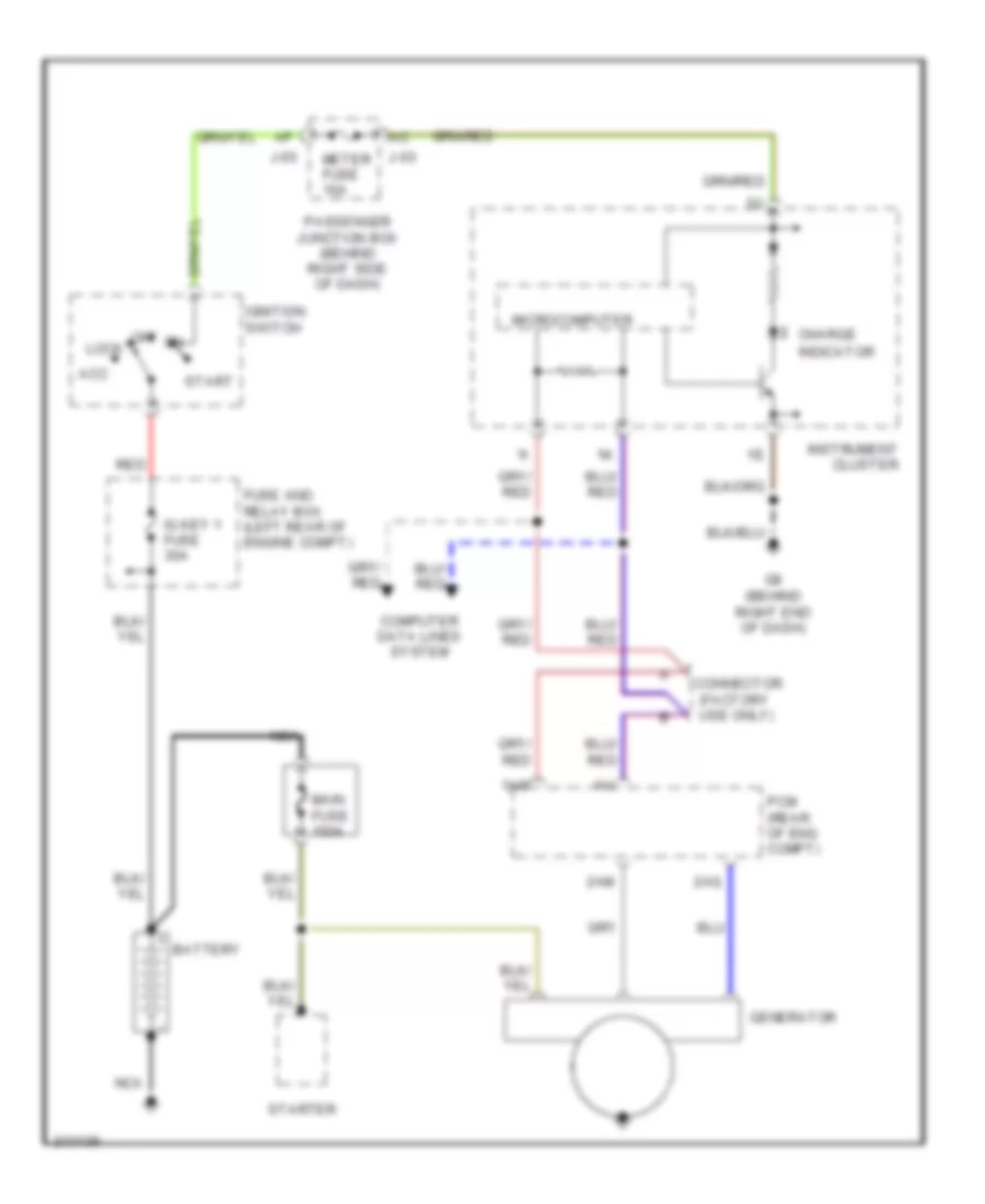
Charging Wiring Diagram for Mazda 3 i 2005
List of elements for Charging Wiring Diagram for Mazda 3 i 2005:
- 1ai
- 1am
- 2am
- 2aq
- Acc
- Battery
- Charge
- Computer data lines system
- Connector (factory use only)
- Fuse and relay box (left rear of engine compt)
- G8 (behind right end of dash)
- Generator
- Ig key 1 fuse 30a
- Ignition switch
- Indicator
- Instrument cluster
- J-03
- Lock
- Main fuse 150a
- Meter fuse 10a
- Microcomputer
- Nca
- Off
- Passenger junction box (behind right side of dash)
- Pcm (rear of eng compt)
- Red
- Start
- Starter
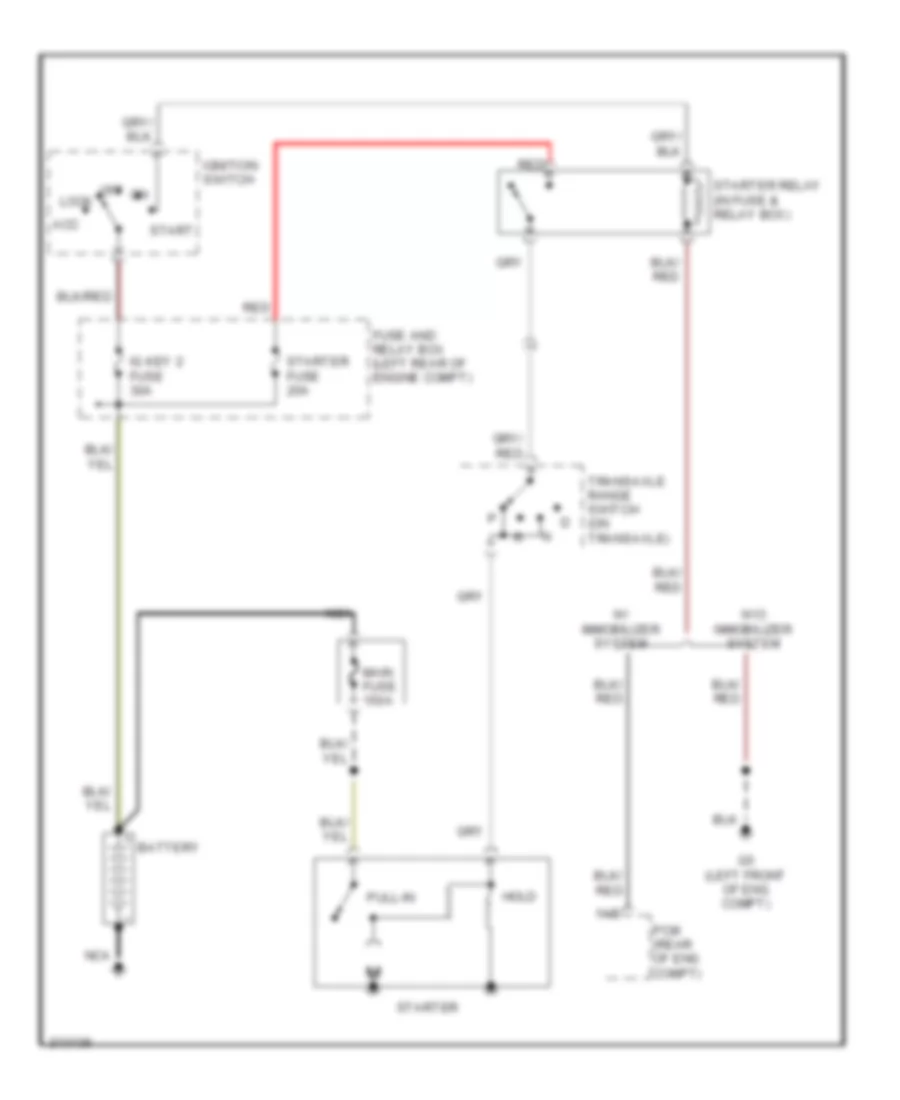
Starting Wiring Diagram, A/T for Mazda 3 i 2005
List of elements for Starting Wiring Diagram, A/T for Mazda 3 i 2005:
- 1ab
- Acc
- Battery
- Fuse and relay box (left rear of engine compt)
- G5 (left front of eng compt)
- Hold
- Ig key 2 fuse 30a
- Ignition switch
- Lock
- Main fuse 150a
- Nca
- Off
- Pcm (rear of eng compt)
- Pull-in
- Red
- Start
- Starter
- Starter fuse 20a
- Starter relay (in fuse & relay box)
- Transaxle range switch (on transaxle)
- W/ immobilizer system
- W/o immobilizer system
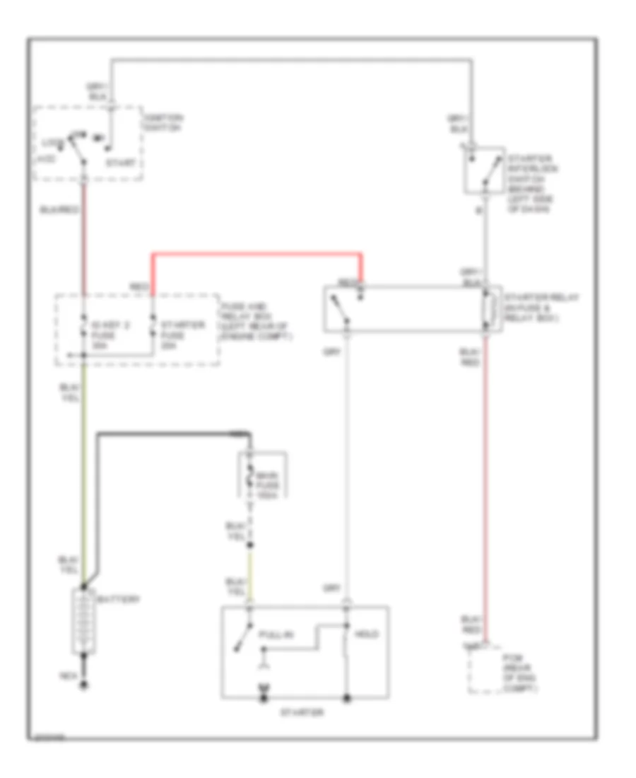
Starting Wiring Diagram, M/T for Mazda 3 i 2005
List of elements for Starting Wiring Diagram, M/T for Mazda 3 i 2005:
- 1ab
- Acc
- Battery
- Fuse and relay box (left rear of engine compt)
- Hold
- Ig key 2 fuse 30a
- Ignition switch
- Lock
- Main fuse 150a
- Nca
- Off
- Pcm (rear of eng compt)
- Pull-in
- Red
- Start
- Starter
- Starter fuse 20a
- Starter interlock switch (behind left side of dash)
- Starter relay (in fuse & relay box)
SUPPLEMENTAL RESTRAINTS
Supplemental Restraints Wiring Diagram (1 of 2) for Mazda 3 i 2005
List of elements for Supplemental Restraints Wiring Diagram (1 of 2) for Mazda 3 i 2005:
- 2aa
- 2ab
- 2ac
- 2ad
- 2ae
- 2af
- 2ag
- 2ah
- 2ai
- 2aj
- 2ak
- 2al
- 2am
- 2an
- Ac j-05
- Driver side buckle switch
- Driver-side curtain air bag module
- Driver-side front buckle pre-tensioner
- Driver-side side air bag module
- Driver-side side air bag sensor
- G11 (below driver's seat)
- G12 (below center console)
- Hot in run or start
- Inflator
- Nca
- Passenger junction box (pjb) (right side of dash)
- Passenger side buckle switch
- Passenger-side curtain air bag module
- Passenger-side front buckle pre-tensioner
- Passenger-side side air bag module
- Passenger-side side air bag sensor
- Sas 2 fuse 7.5a
- Sas control module (below center console)
- Seat track position sensor (below right front seat)
- Seat weight sensor (left) (left front seat cushion)
- Seat weight sensor (right) (right front seat cushion)
- Seat weight sensor control module (below right front seat)
- Shorting bar
Supplemental Restraints Wiring Diagram (2 of 2) for Mazda 3 i 2005
List of elements for Supplemental Restraints Wiring Diagram (2 of 2) for Mazda 3 i 2005:
- Clock spring
- Crash zone sensor (front of vehicle)
- Data link connector (dlc) 2 (under lower left side of dash)
- Driver-side side air bag module
- Hot in run or start
- Inflator 1
- Inflator 2
- J-03 am
- Nca
- Passenger air bag deactivation indicator
- Passenger junction box (pjb) (right side of dash)
- Passenger-side side air bag module
- Sas control module (below center console)
- Sas fuse 10a
- Shorting bar
TRANSMISSION
A/T Wiring Diagram (1 of 2) for Mazda 3 i 2005
List of elements for A/T Wiring Diagram (1 of 2) for Mazda 3 i 2005:
- (at transaxle range switch)
- (behind left side of dash) brake switch
- 1aa
- 1ai
- 1am
- 1at
- 1au
- 1av
- 1ax
- 1ay
- 1az
- 1ba
- 1bb
- 1bd
- 1be
- 1bf
- 1bg
- 1bh
- Back fuse 10a
- Computer data lines system
- Control valve body
- Engine controls system
- Exterior lights system
- G16
- G5 (left front of engine compt)
- G6 (at left rear of engine)
- Hot in run
- Input turbine speed sensor (on transaxle)
- J-01
- J-05
- Passenger junction box (behind right side of dash)
- Powertrain control module (rear of engine compt)
- Pressure control solenoid
- R position
- Red
- Shift sol a
- Shift sol b
- Shift sol c
- Shift sol d
- Shift sol e
- Transaxle fluid temp sensor
- Transaxle range switch (on transaxle)
- Vehicle speed sensor (on transaxle)
A/T Wiring Diagram (2 of 2) for Mazda 3 i 2005
List of elements for A/T Wiring Diagram (2 of 2) for Mazda 3 i 2005:
- 1-4
- A/t
- Computer data lines system
- Down sw
- Eng b + fuse 10a
- Eng bar 1 fuse 10a
- Eng bar 2 fuse 10a
- Engine controls system
- Engine fuse 20a
- Engine fuse 30a
- Et control relay
- F/pump fuse 15a
- Fuse & relay box (left rear of engine compt)
- G7 (behind left side of dash)
- G8 (behind right end of dash)
- Horn fuse 15a
- Hot at all times
- Hot in run or start
- Instrument cluster
- J-01
- J-03
- M range
- Main relay
- Meter fuse 10a
- Micro- computer
- Not p position
- P position range
- Passenger junction box (behind right side of dash)
- Red
- Selector indicator circuit
- Selector lever component (in center console)
- Shift interlock system
- Shift-lock relay
- Up sw
WARNING SYSTEMS
Chime Wiring Diagram for Mazda 3 i 2005
List of elements for Chime Wiring Diagram for Mazda 3 i 2005:
- Brake
- Brake switch 2 (at top of brake pedal)
- Buzzer
- Computer data lines system
- D j-04
- Door
- Driver side buckle switch
- Driver's seat)
- Fuse & relay box (left rear of engine compt)
- G11 (below
- G11 (below driver's seat)
- G12 (behind center console)
- G12 (below center console)
- G8 (behind right end of dash)
- Hot at all times
- Hot in run & start
- Instrument cluster
- J-01 r
- J-03 ac
- Key reminder switch
- Left rear door latch switch/ left rear door lock actuator
- Master door lock assembly
- Meter fuse 66 10a
- Microcomputer
- Nca
- Parking brake switch (at base of parking brake lever)
- Passenger junction box (behind right side of dash)
- Passenger side buckle switch
- Red
- Right front door latch switch/ right front door lock actuator
- Right rear door latch switch/ right rear door lock actuator
- Room fuse 15a
- Sas control module (below center console)
- Seat belts
- Tripmeter switch
- U j-06
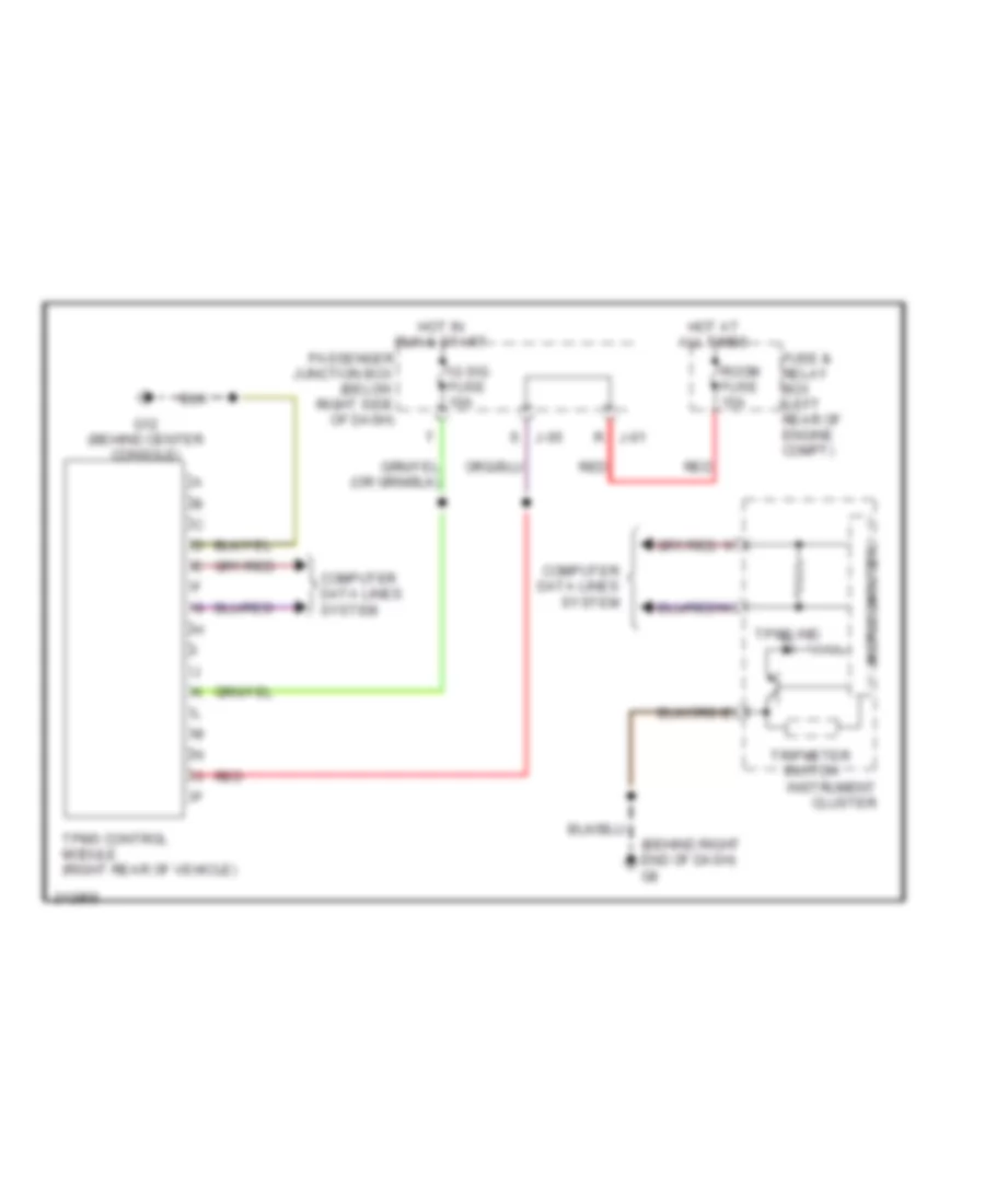
Tire Pressure Monitoring Wiring Diagram for Mazda 3 i 2005
List of elements for Tire Pressure Monitoring Wiring Diagram for Mazda 3 i 2005:
- (behind right end of dash) g8
- Computer data lines system
- Fuse & relay box (left rear of engine compt)
- G12 (behind center console)
- Hot at all times
- Hot in run & start
- Ig sig fuse 10a
- Instrument cluster
- J-01 r
- J-05 s
- Microcomputer
- Passenger junction box (below right side of dash)
- Red
- Room fuse 15a
- Tpms control module (right rear of vehicle)
- Tpms ind
- Tripmeter switch
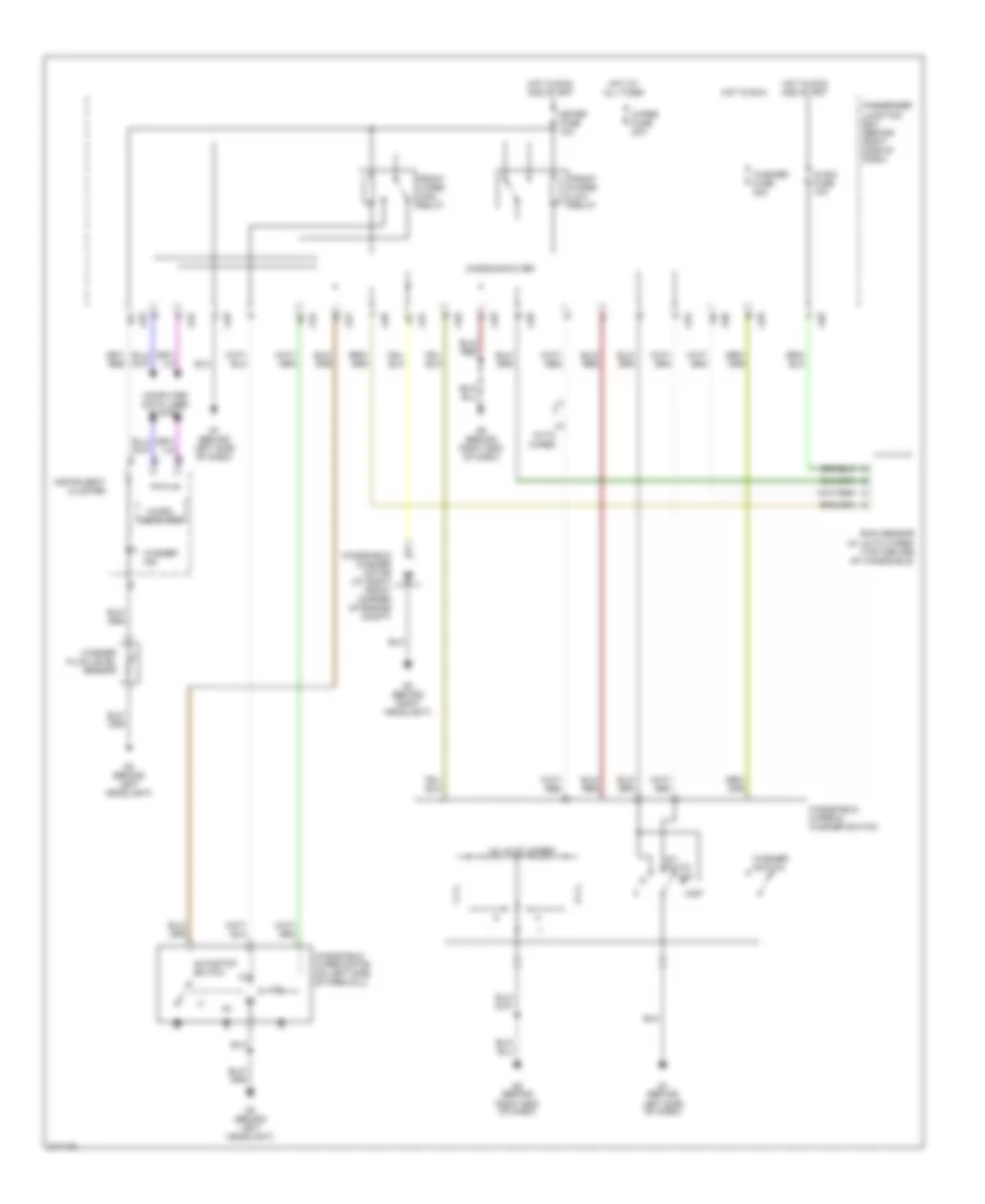
WIPER/WASHER
Front Wiper/Washer Wiring Diagram for Mazda 3 i 2005
List of elements for Front Wiper/Washer Wiring Diagram for Mazda 3 i 2005:
- (w/ auto wiper)
- Auto wiper
- Autostop switch
- Computer data lines system
- Front wiper high relay
- Front wiper low relay
- G2 (behind left headlight)
- G3 (behind right headlight)
- G7 (behind left side of dash)
- G8 (behind right end of dash)
- Hot at all times
- Hot in run
- Hot in run and start
- Ig sig fuse 10a
- Instrument cluster
- Int (auto)
- J-01
- J-03
- J-04
- J-05
- J-06
- Meter fuse 10a
- Micro- computer
- Microcomputer
- Mist
- Off
- Passenger junction box (behind right side of dash)
- Rain sensor (w/ auto wiper) (top center of windshield)
- W/
- Washer fluid level sensor
- Washer fuse 20a
- Washer ind
- Washer switch
- Windshield washer motor (at right front corner of engine compt)
- Windshield wiper & washer switch
- Windshield wiper motor (on left side of firewall)
- Wiper fuse 20a
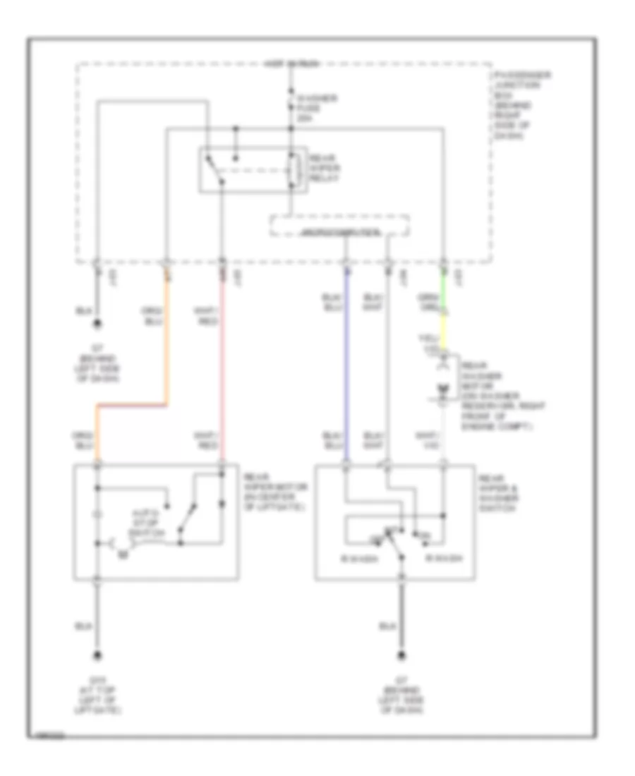
Rear Washer/Wiper Wiring Diagram for Mazda 3 i 2005
List of elements for Rear Washer/Wiper Wiring Diagram for Mazda 3 i 2005:
- Auto- stop switch
- G15 (at top left of liftgate)
- G7 (behind left side of dash)
- Hot in run
- Int
- J-03
- J-04
- J-05
- Microcomputer
- Off
- Passenger junction box (behind right side of dash)
- R wash
- Rear washer motor (on washer reservoir, right front of engine compt)
- Rear wiper & washer switch
- Rear wiper motor (in center of liftgate)
- Rear wiper relay
- Washer fuse 20a

 Čeština
 Dansk
Dansk Deutsch
 Ελληνικά
 English
 English
 Español
 Suomi
Suomi Français
 Français
 עברית
עברית Hrvatski
 Magyar
 Italiano
 日本語
日本語 한국어
한국어 Polski
 Português
 Português
 Română
 Русский
 Slovenčina
 Slovenščina
 Svenska
 Türkçe
 中文 (中国)