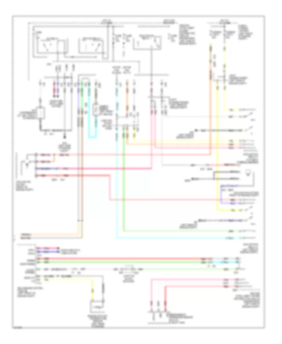
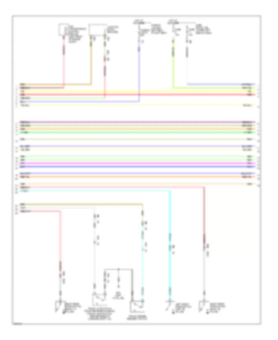
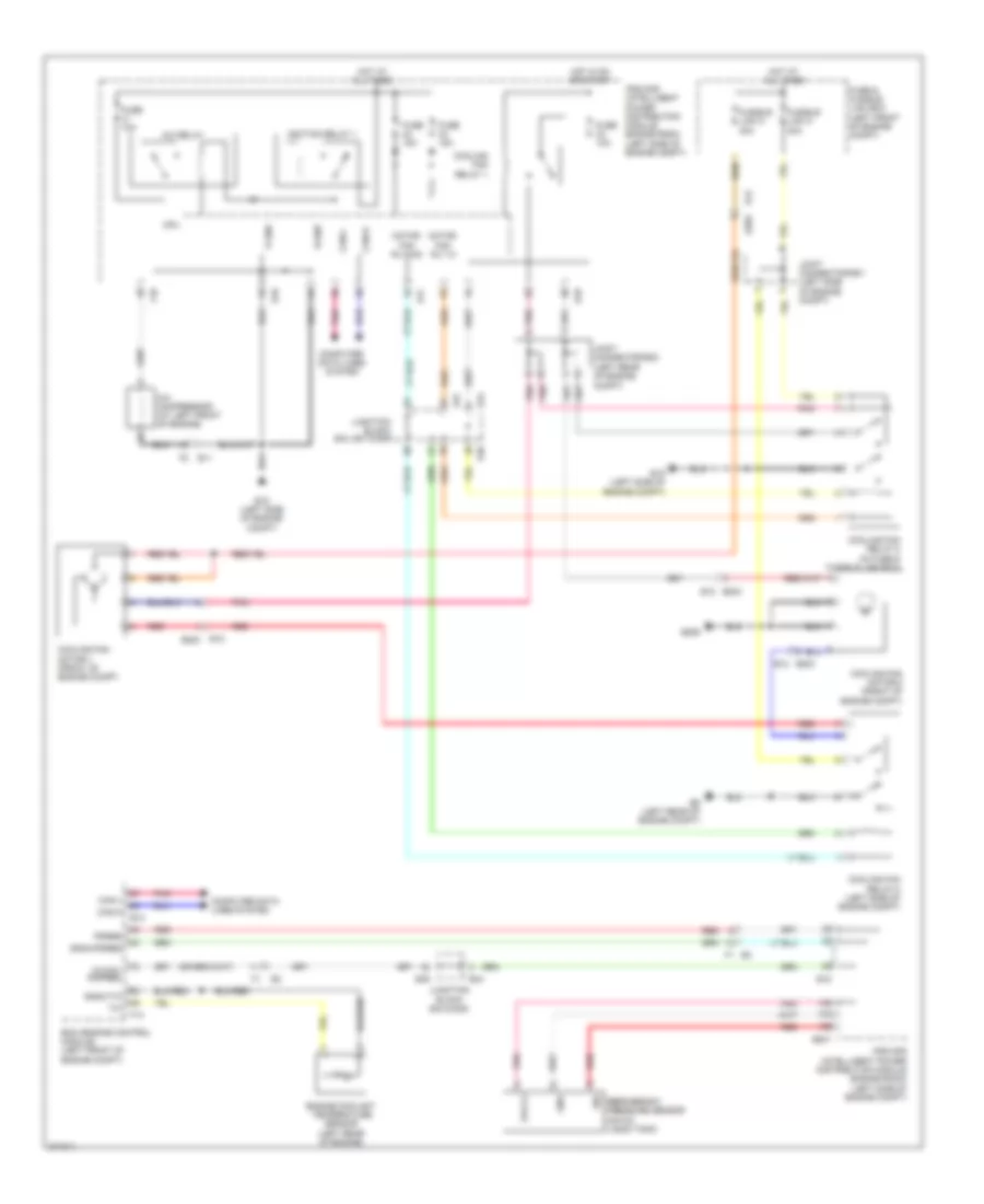
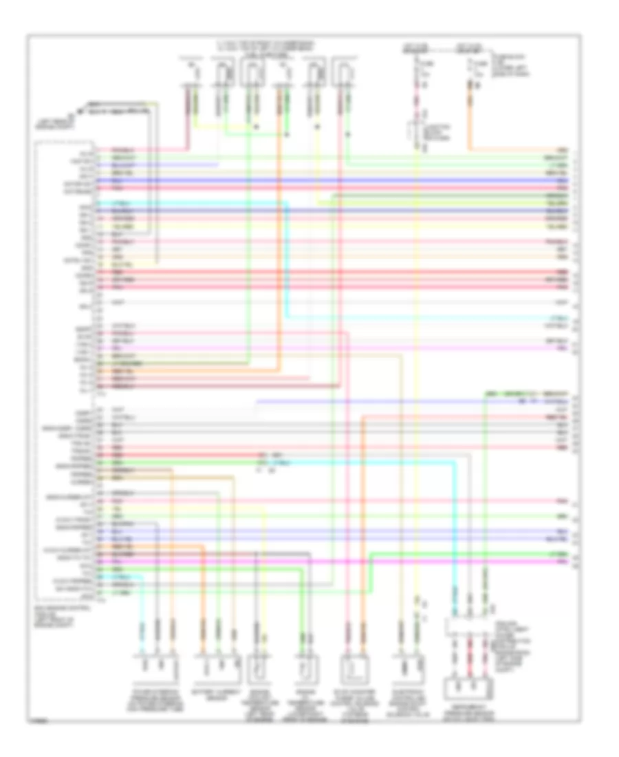
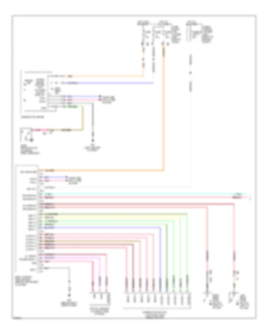
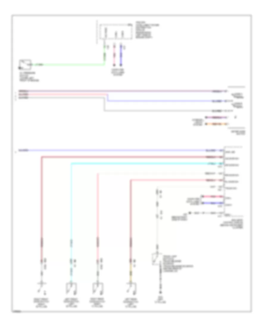
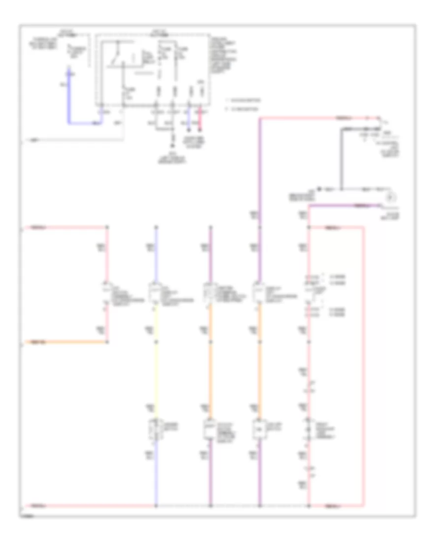
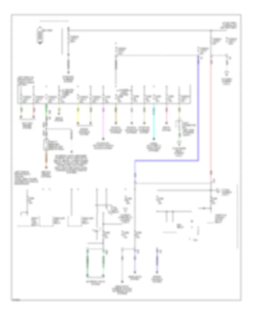
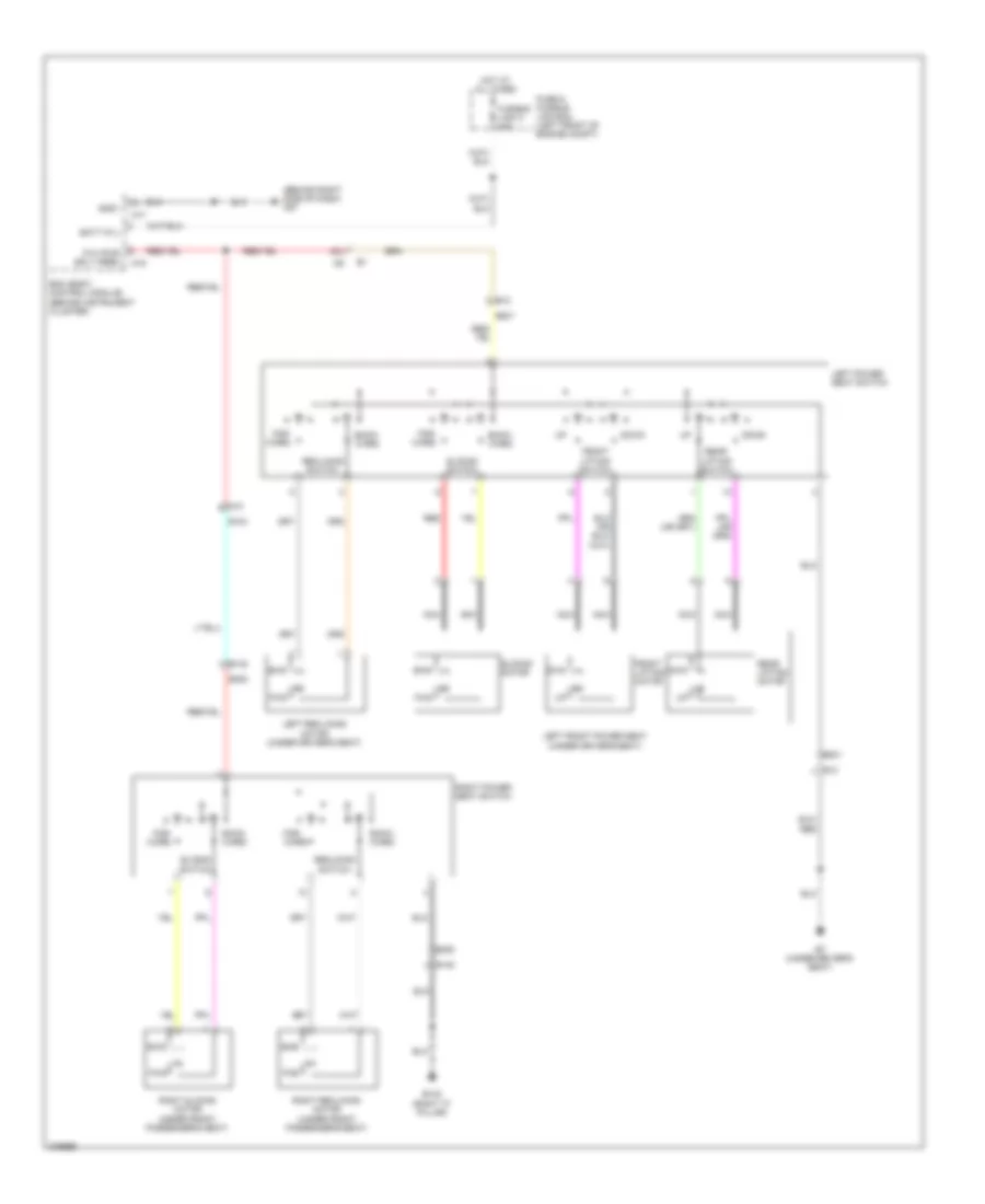
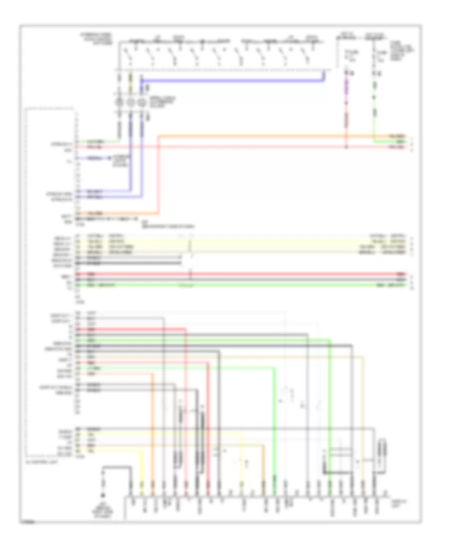
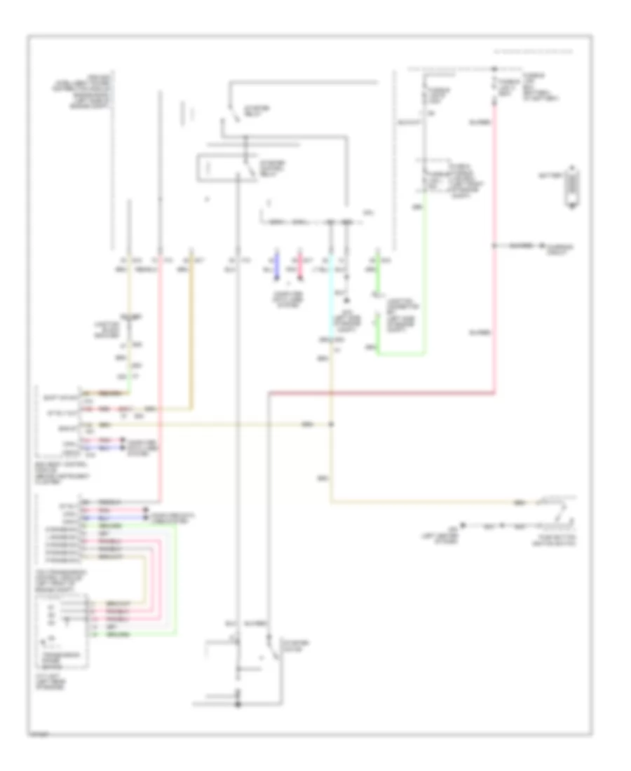
AIR CONDITIONING
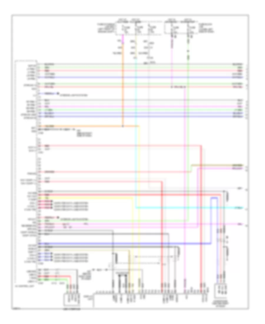
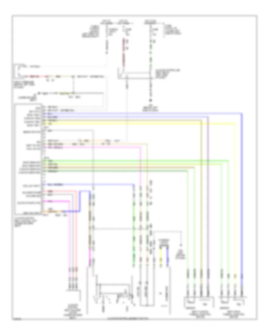
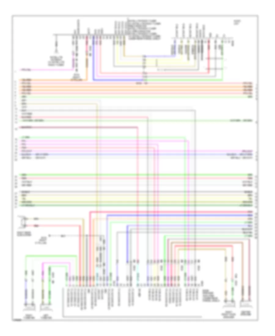
Automatic A/C Wiring Diagram (1 of 2) for Nissan Maxima SV 2012
 https://portal-diagnostov.com/license.html
Automotive Electricians Portal FZCO
Automotive Electricians Portal FZCO
https://portal-diagnostov.com/license.html
https://portal-diagnostov.com/license.html
Automotive Electricians Portal FZCO
Automotive Electricians Portal FZCO
List of elements for Automatic A/C Wiring Diagram (1 of 2) for Nissan Maxima SV 2012:
- 23g
- A/c & av switch assembly (w/o monochrome display)
- A/c auto amp (behind center of dash)
- A/c display unit
- A/c switch assembly (w/ monochrome
- Acc
- Amb sns
- Av control unit (w/o monochrome display)
- Bat
- Bcm (body control module) (behind instrument cluster)
- Blower motor (behind right side of dash)
- Blwr fan rly
- Can-h
- Can-l
- Computer data lines system
- Defogger system
- Display)
- Driver side air mix door motor (behind left center of dash)
- E30
- Fan pwm
- Front blower motor relay
- Fuse 10a
- Fuse 15a
- Fuse block (j/b) (lower left side of dash)
- Fusible link box (battery) (at battery)
- Fusible link c 100a
- Gnd
- Gnd (power)
- Hot at all times
- Hot in acc or on
- Hot in on or start
- Ign
- Ill+
- Ill-
- In-vehicle sensor (behind left center of dash)
- Incar sns
- Intake door motor (behind center of dash)
- Intake sensor (behind right side of dash)
- Intake sns
- Interior lights system
- Lan sig
- M125
- M152
- M156
- M160
- M163
- M19
- M33
- M57 (behind right side of dash)
- M61 (behind left side of dash)
- M79 (left center of dash)
- Mode door motor (behind left center of dash)
- Passenger side air mix door motor (behind right side of dash)
- Pnk
- Rr def on
- Sns gnd
- Sun sns
- Sunload sensor (on left defroster grille)
- Vactr
- W/ monochrome display
- W/ navigation system
- W/o monochrome display
- W/o navigation system
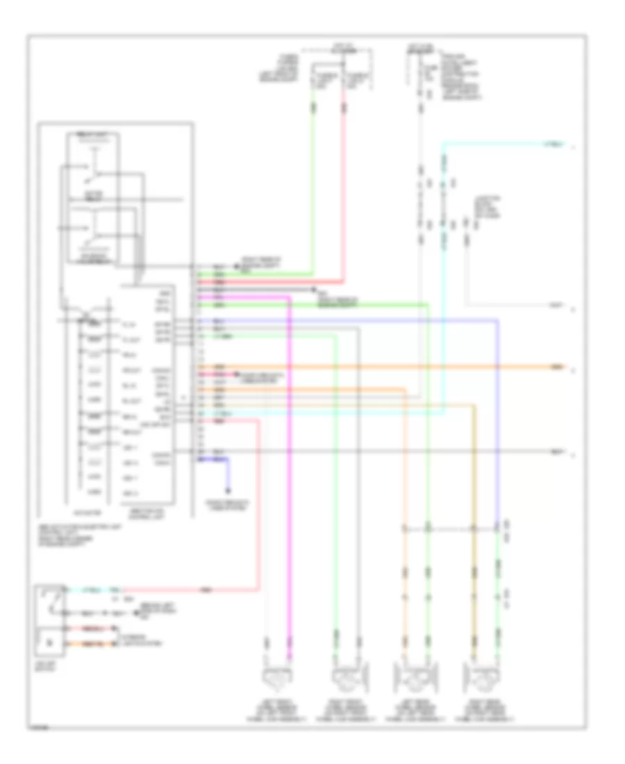
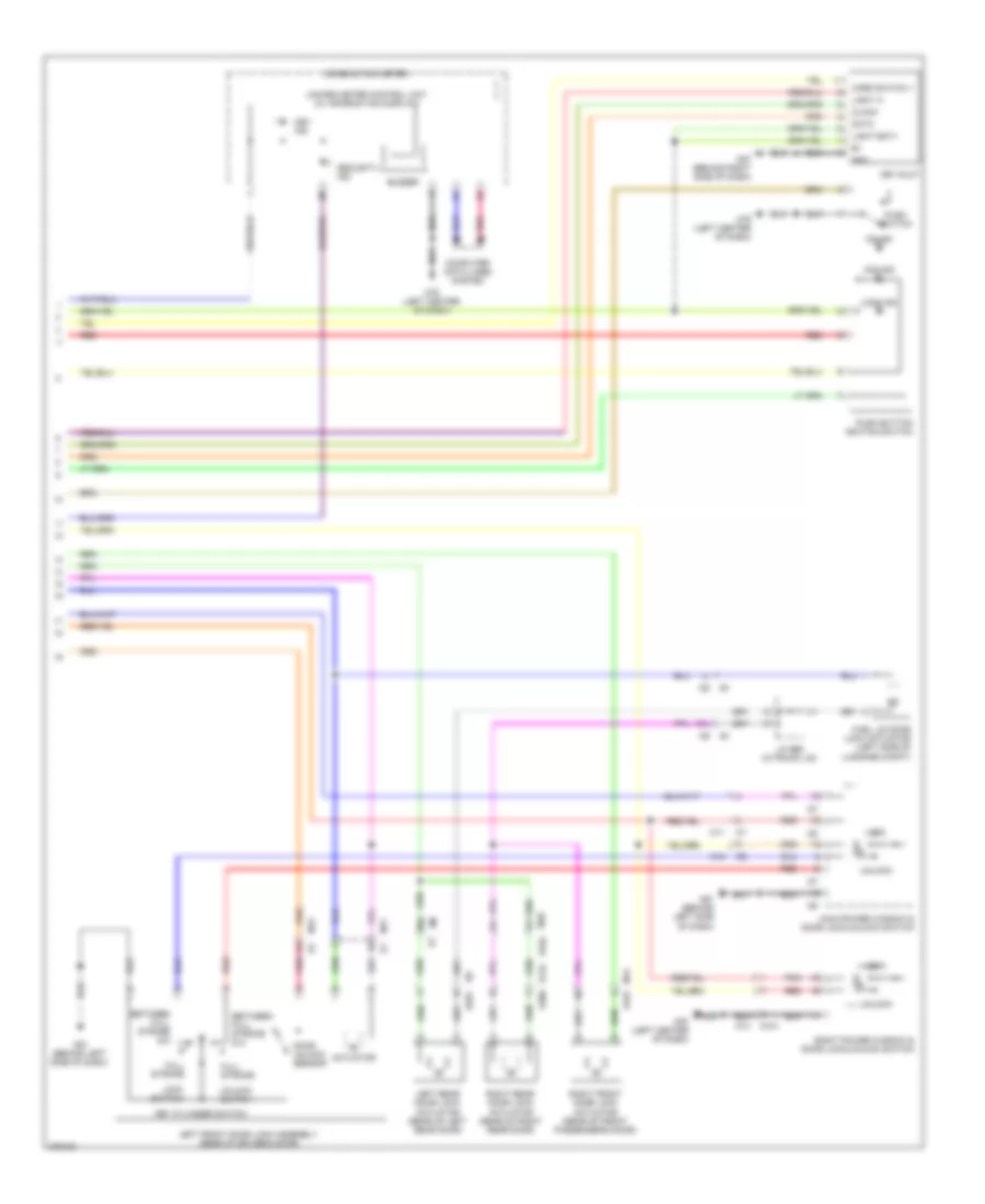
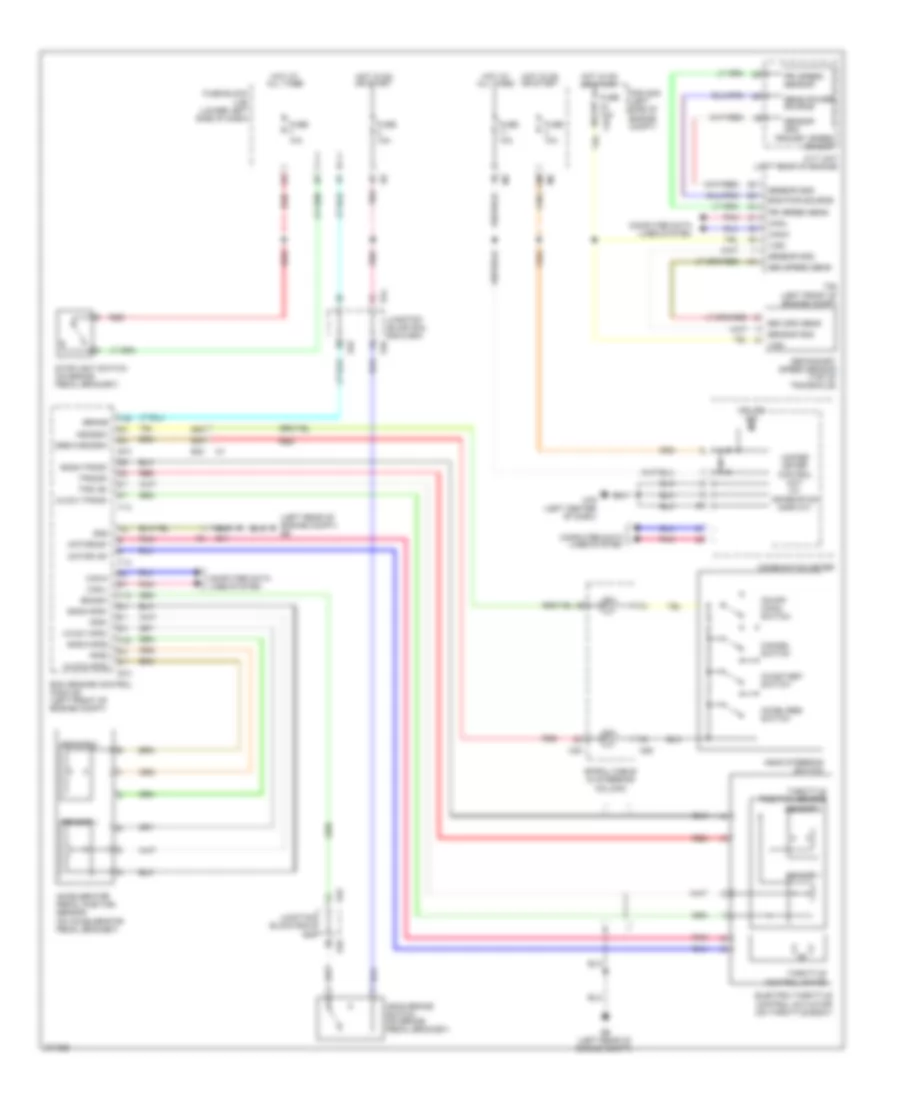
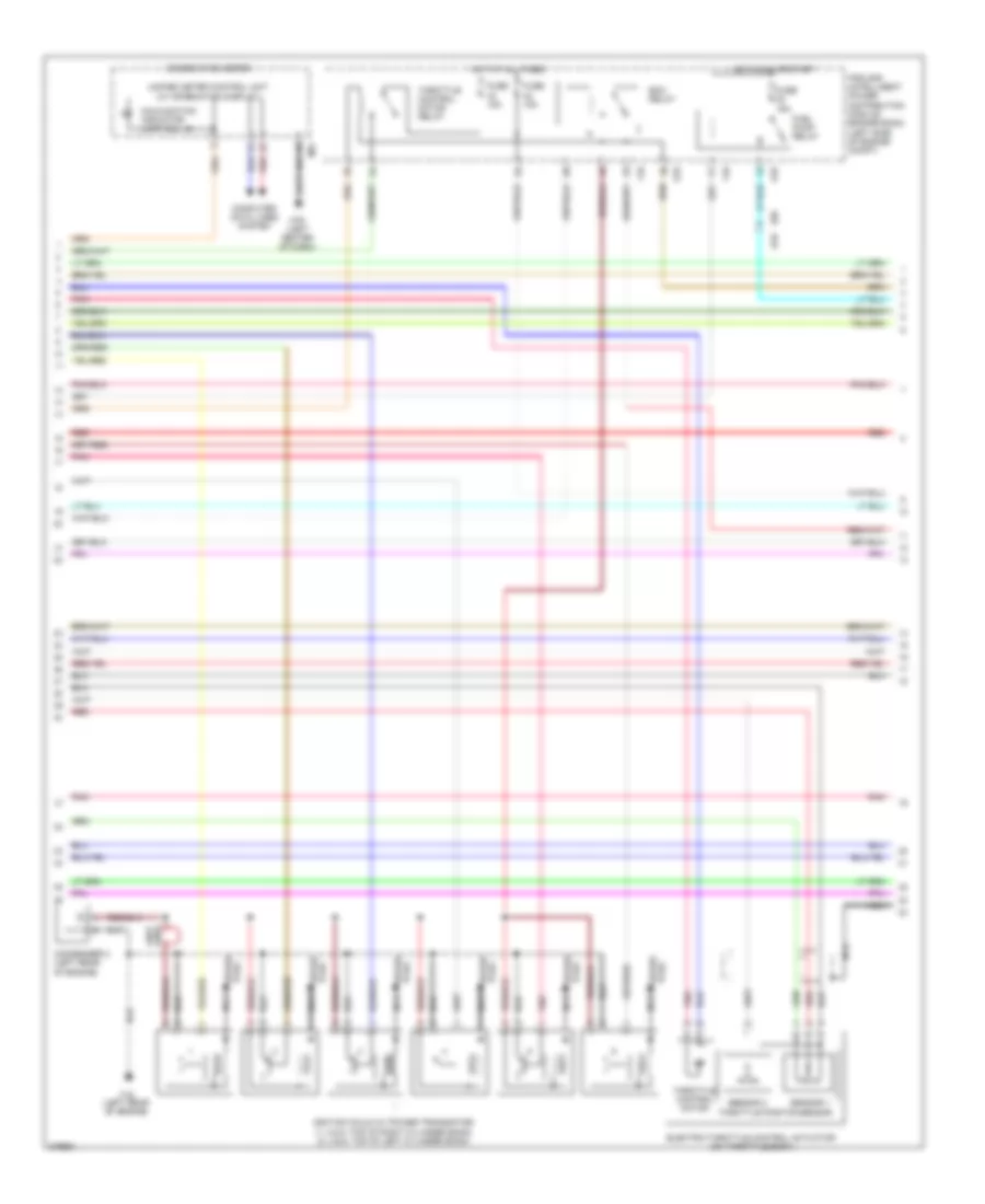
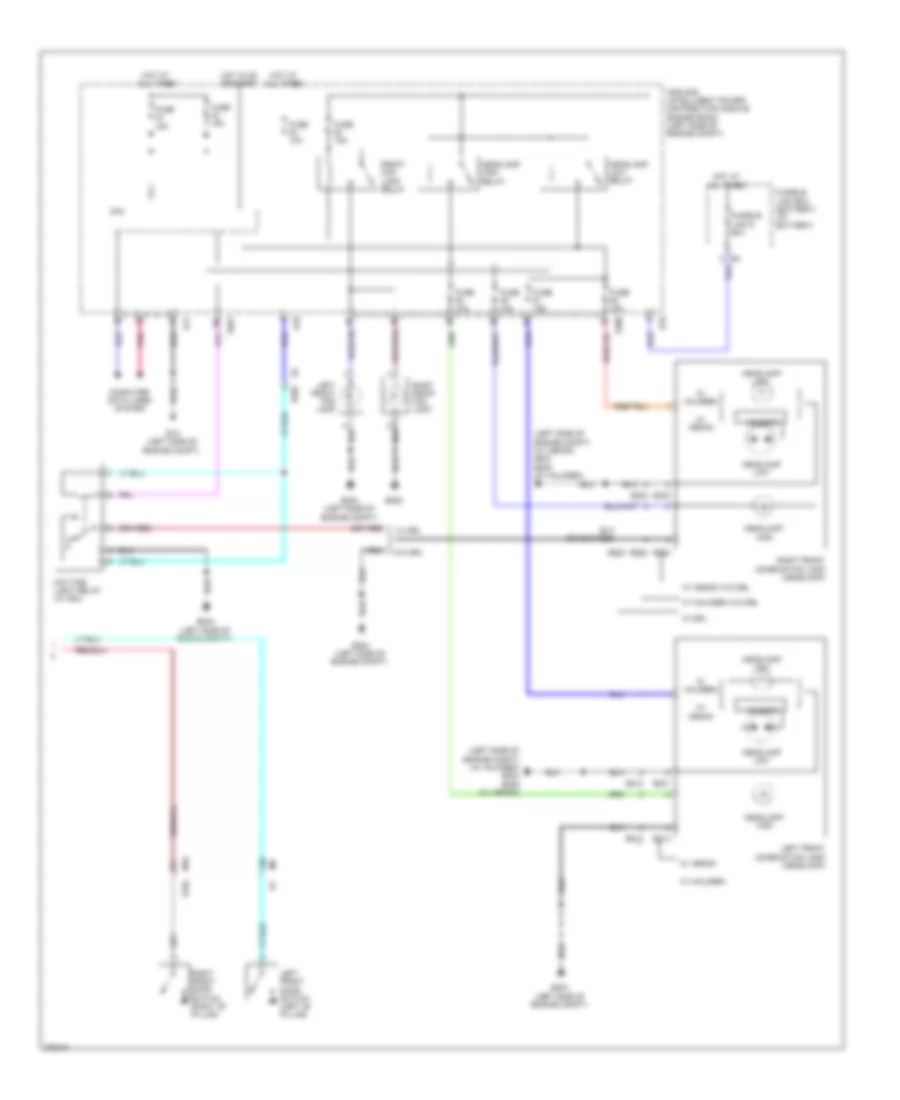
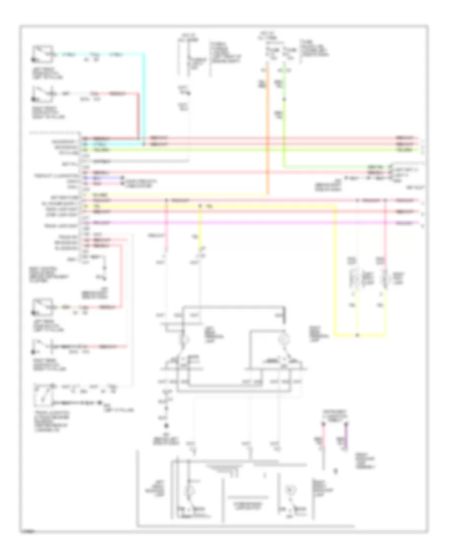
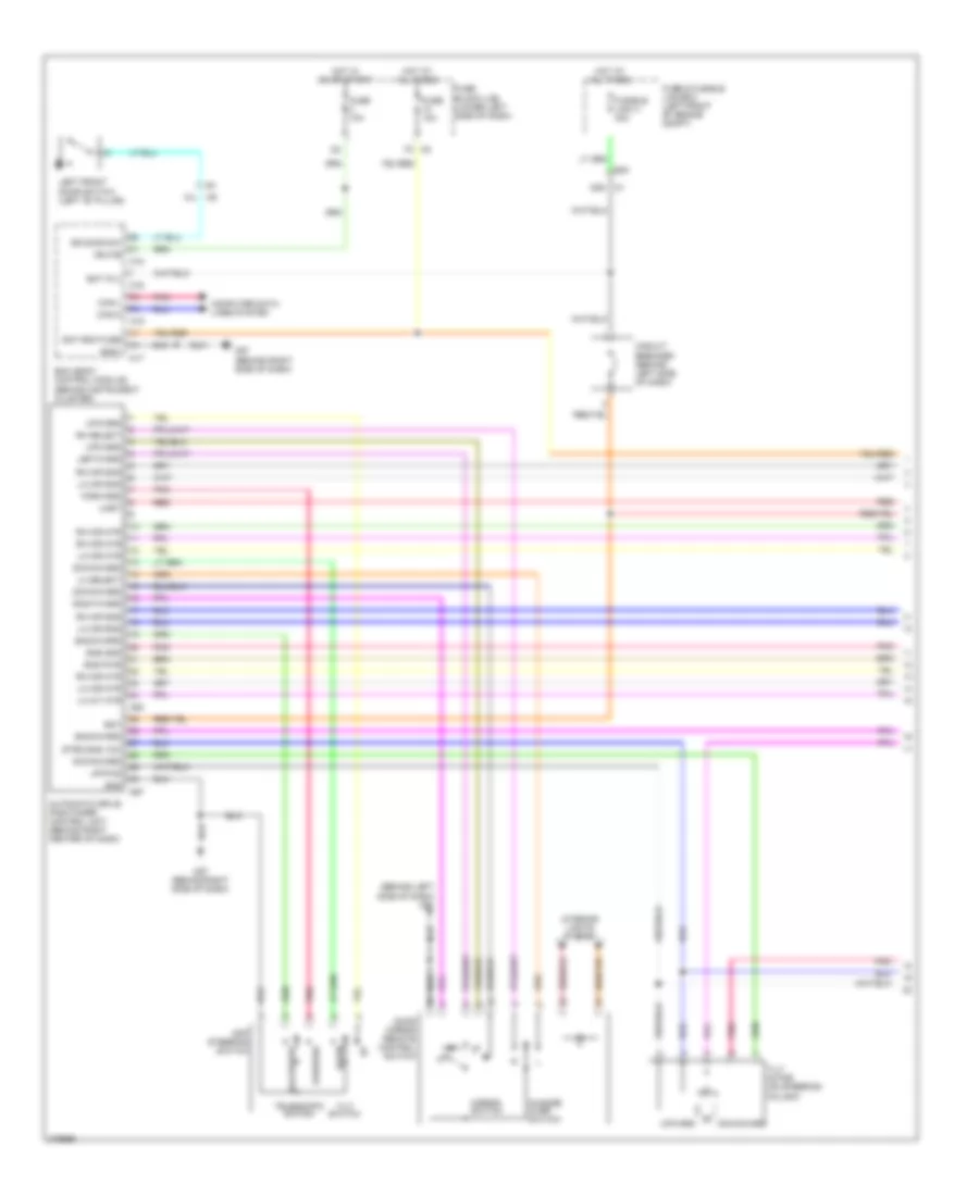
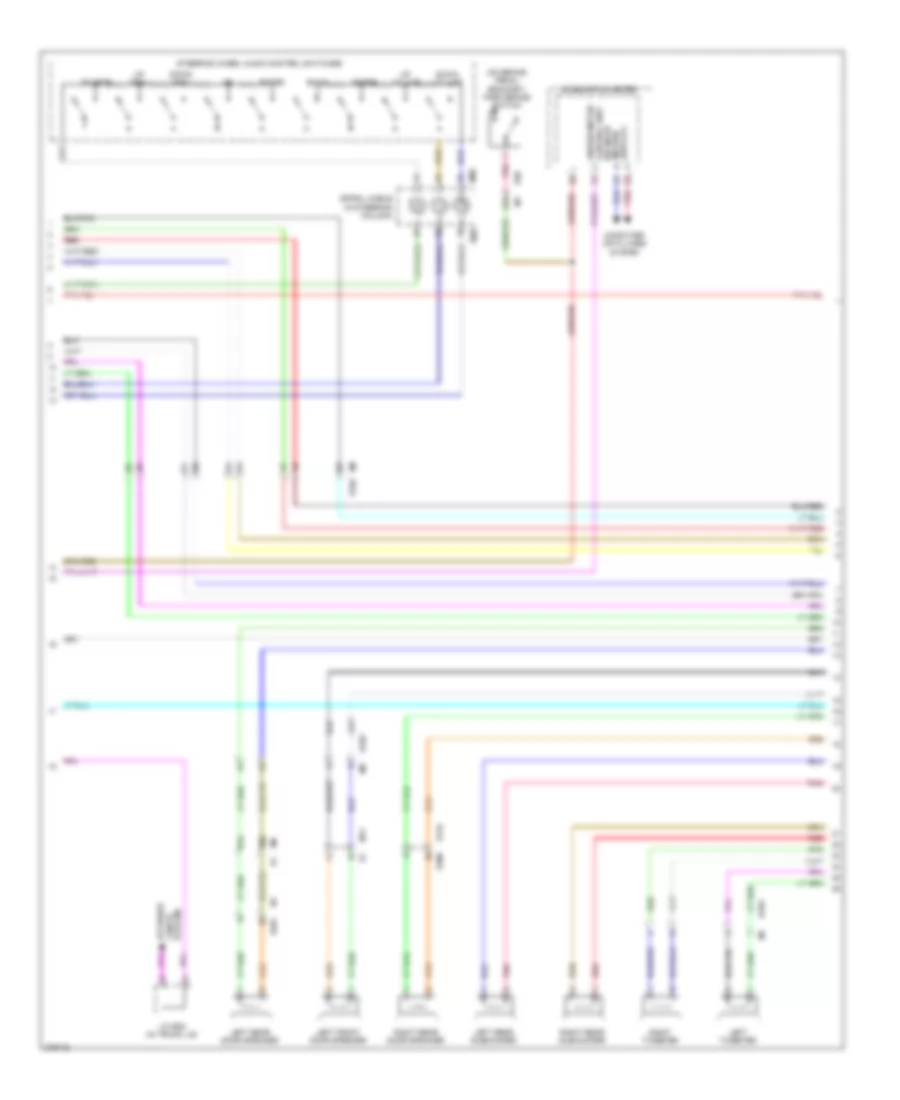
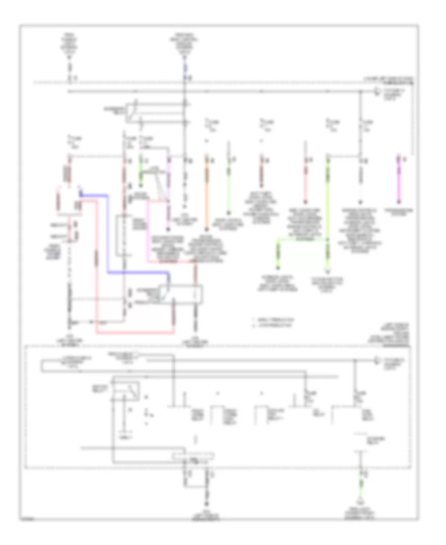
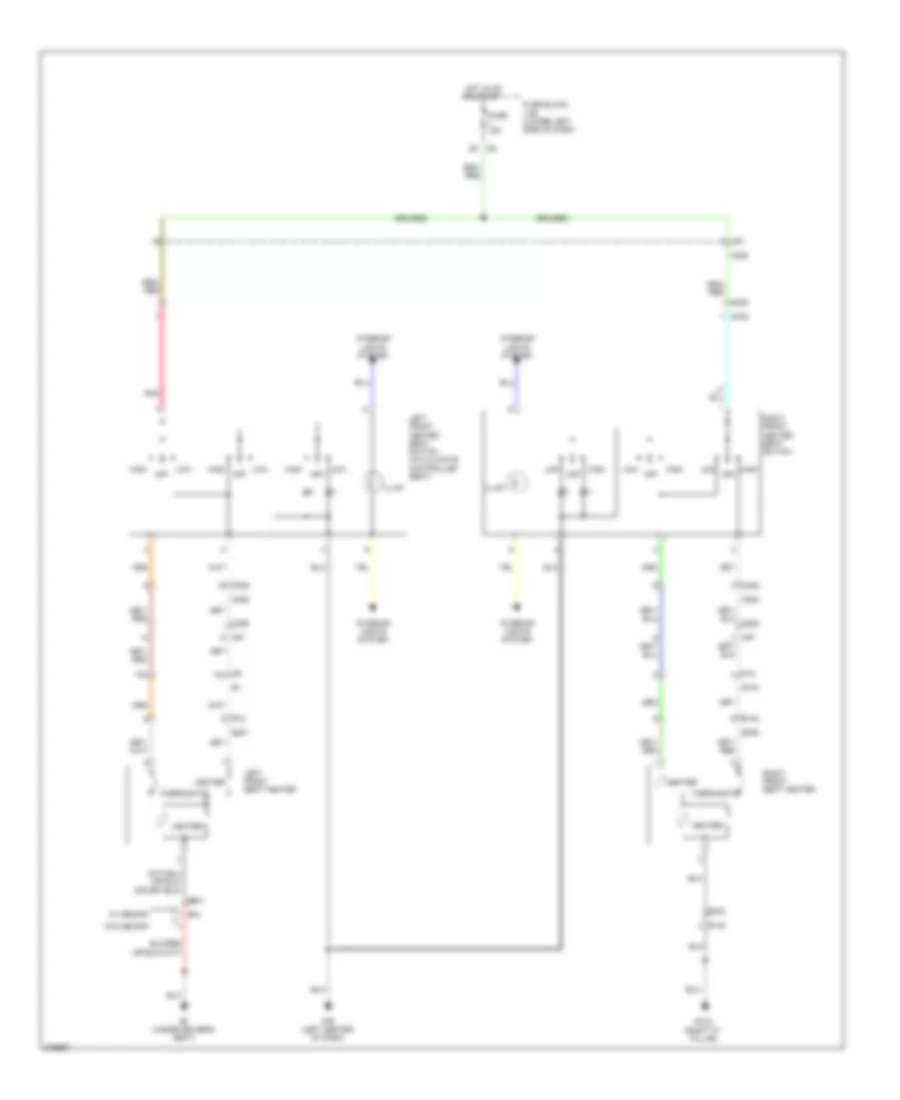
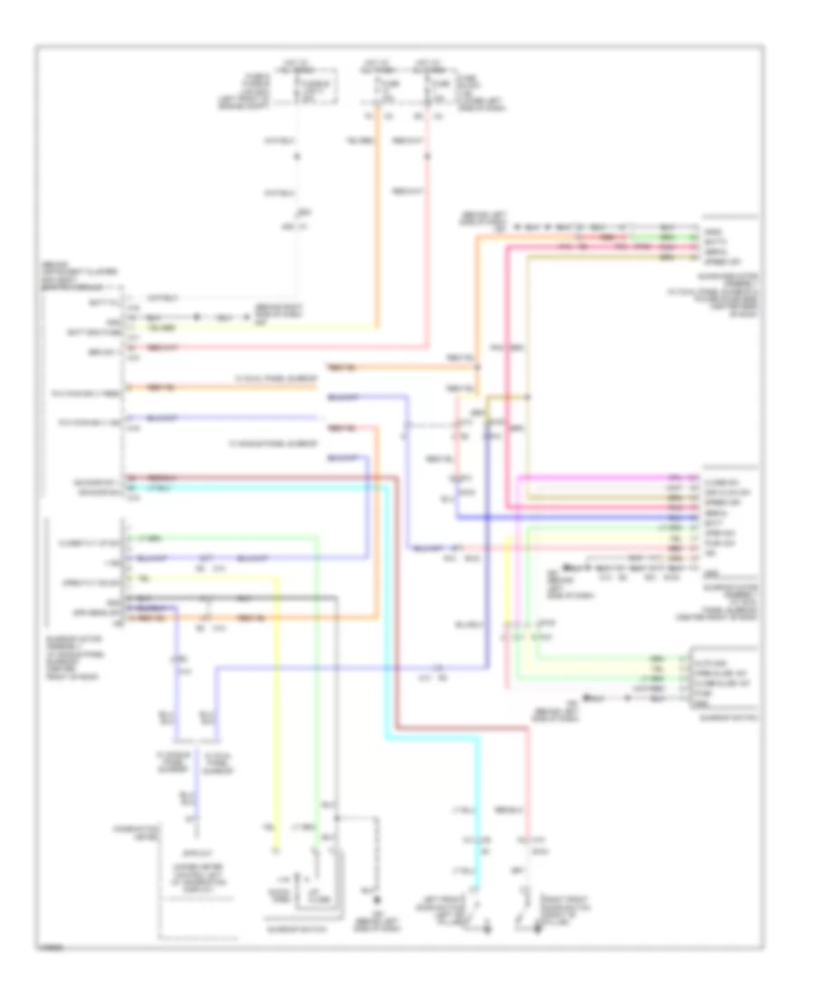
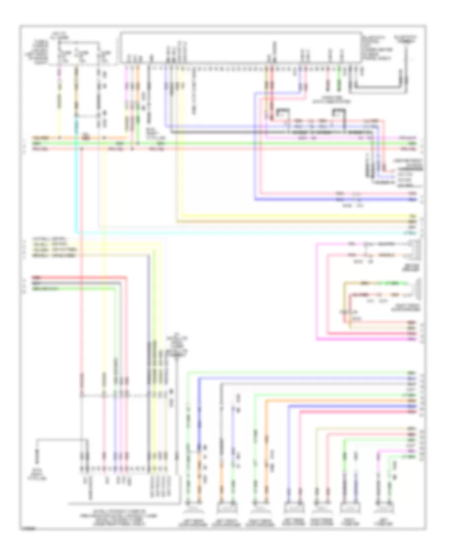
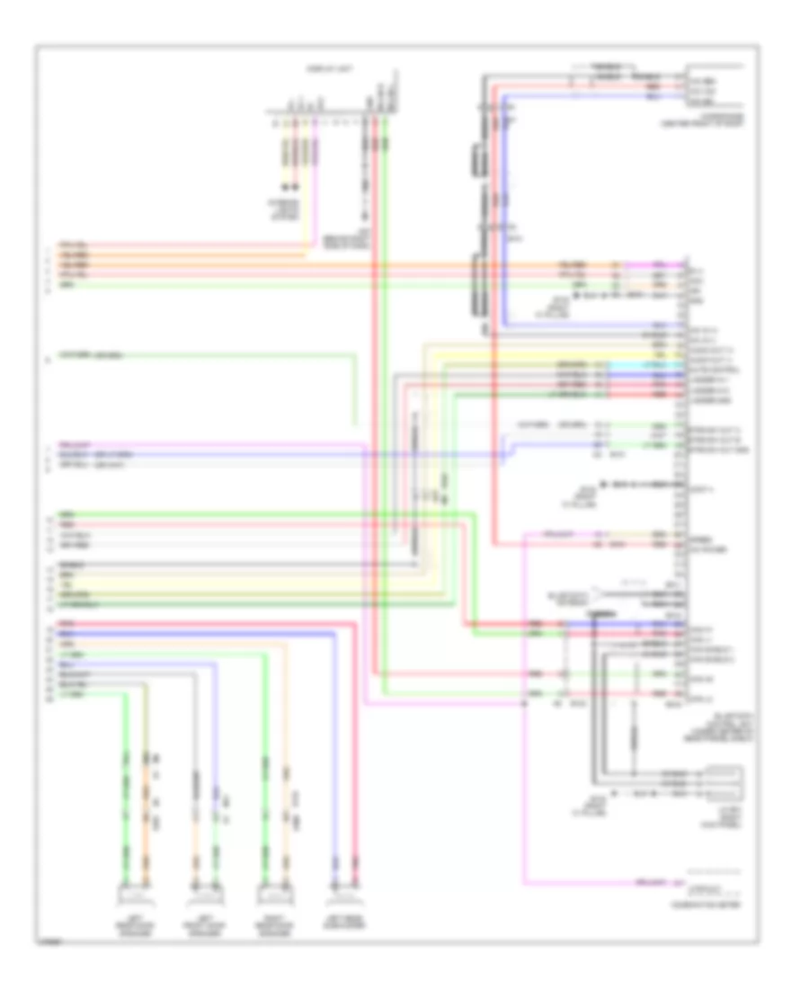
Automatic A/C Wiring Diagram (2 of 2) for Nissan Maxima SV 2012
List of elements for Automatic A/C Wiring Diagram (2 of 2) for Nissan Maxima SV 2012:
- 25g
- 32g
- A/c compressor (at left front of engine)
- A/c relay
- Ambient sensor (left front of vehicle)
- Avcc2
- Avcc2- pdpres
- Can-h
- Can-l
- Computer data lines system
- Cooling fan motor-1 (front of engine compt)
- Cooling fan motor-2 (front of engine compt)
- Cooling fan relay 1
- Cooling fan relay-2 (left side of engine compt)
- Cooling fan relay-3 (in fuse & fusible link box)
- Cpu
- E10
- E11
- E12
- E12 e203
- E15 (left side of engine compt)
- E17
- E18
- E201
- E203
- E209
- E3 f1
- E30
- E44
- E45
- E47
- E48
- E9 (left rear of engine compt)
- Ecm (engine control module) (left front of engine compt)
- Engine coolant temperature sensor (left rear of engine)
- F10
- F13
- Fuse & fusible link box (left front of engine compt)
- Fuse 10a
- Fuse 15a
- Fusible link k 40a
- Fusible link m 40a
- Gnd
- Gnda-pdres
- Gnda-tw
- Hot at all times
- Hot in on or start
- Ignition relay 1
- Ipdm e/r (intelligent power distribution module engine room) (left side of engine compt)
- Joint connector-e01 (left side of engine compt)
- Joint connector-e02 (left rear of engine compt)
- Junction block e44 & e45
- Junction block e44, e47 & e48
- Motor fan rly hi
- Motor fan rly mid
- P-gnd
- Pdres
- Pnk
- Red
- Refrigerant pressure sensor (on a/c liquid tank)
- S-gnd
- Sig
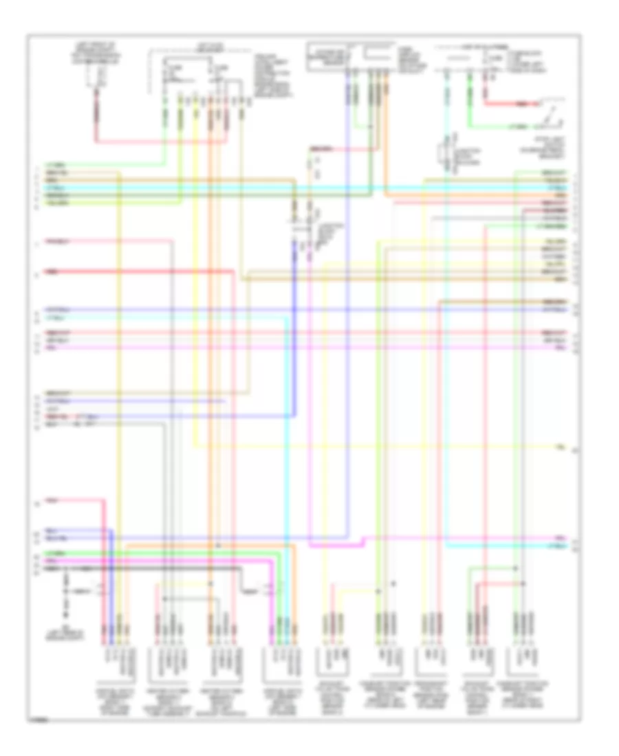
ANTI-LOCK BRAKES
Anti-lock Brakes Wiring Diagram (1 of 2) for Nissan Maxima SV 2012
List of elements for Anti-lock Brakes Wiring Diagram (1 of 2) for Nissan Maxima SV 2012:
- (behind left side of dash) m61
- (right rear of engine compt) e33
- 75g
- Abs actuator & electric unit (control unit) (right rear corner of engine compt)
- Abs/tcs/vdc control unit
- Actuator
- B31 c5
- Bls
- Can-h
- Can-l
- Can-m2
- Can-p2
- Computer data lines system
- Dp fl
- Dp fr
- Dp rl
- Dp rr
- Ds fl
- Ds fr
- Ds rl
- Ds rr
- E18
- E29 b10
- E30 m1
- E33 (right rear of engine compt)
- E44
- E46
- E47
- E49
- Fl in
- Fl out
- Fr in
- Fr out
- Fuse & fusible link box (left front of engine compt)
- Fuse 10a
- Fusible link f 50a
- Fusible link g 30a
- Gnd
- Hot at all times
- Hot in on or start
- Hsv 1
- Hsv 2
- Interior lights system
- Ipdm e/r (intelligent power distribution module engine room) (left side of engine compt)
- Junction block e44, e46, e47 & e49
- Left front wheel sensor (on left front wheel hub assembly)
- Left rear wheel sensor (on left rear wheel hub assembly)
- Motor
- Motor relay
- Pnk
- Red
- Relay unit
- Right front wheel sensor (on right front wheel hub assembly)
- Right rear wheel sensor (on right rear wheel hub assembly)
- Rl in
- Rl out
- Rr in
- Rr out
- Solenoid valve relay
- Usv 1
- Usv 2
- Vdc off sw
- Vdc off switch
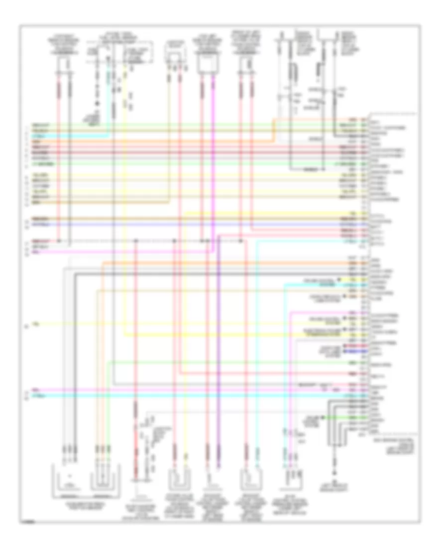
Anti-lock Brakes Wiring Diagram (2 of 2) for Nissan Maxima SV 2012
List of elements for Anti-lock Brakes Wiring Diagram (2 of 2) for Nissan Maxima SV 2012:
- (left side of engine comp)
- (w/ information display) unified meter control unit
- 12m
- 24g
- 31g
- 67g
- 70g
- 77g
- Abs ind
- Brake fluid level switch (on master cylinder
- Brake ind
- Can-h
- Can-l
- Combination meter
- Computer data lines system
- E15
- E30 m1
- Fuse 10a
- Fuse block (j/b) (lower left side of dash)
- Gnd
- Hot at all times
- Hot in on or start
- M1 e30
- M79 (left center of dash)
- Park brake switch (on brake pedal bracket)
- Pnk
- Pwr
- Red
- Reservoir)
- Slip ind
- Steering angle sensor (on steering column)
- Stop light switch (on brake pedal bracket)
- Vdc off ind
- Yaw rate/ side/decel g sensor (under rear of center console)
ANTI-THEFT
Anti-theft Wiring Diagram (1 of 4) for Nissan Maxima SV 2012
List of elements for Anti-theft Wiring Diagram (1 of 4) for Nissan Maxima SV 2012:
- (behind right side of dash) m57
- 11p
- 12v
- 13j
- 14j
- 20g
- 27g
- 57g
- 82g
- Acc led
- As door ant a
- As door ant b
- As door switch
- As request switch
- At device out
- Back door ant a
- Back door ant b
- Bat bcm fuse
- Batt f/l
- Bcm (body control module) (behind instrument cluster)
- Brake sw 1
- Brake sw 2
- Buzzer
- Can-h
- Can-l
- Computer data lines system
- Cpu
- Cvt shift selector (park position) switch (intelligent key system)
- Door lock output all
- Door lock status dr
- Door unlock output as
- Door unlock output dr/fl
- Door unlock output rr/rl
- Dr door ant a
- Dr door ant b
- Dr door switch
- Dr request switch
- E18
- E30
- Eng start sw w/o escl
- Exterior lights system
- Fl flasher
- Fob in switch 1
- Fob reader data
- Fob slot illumination
- Fr flasher
- Fuse & fusible link box (left front of engine compt)
- Fuse 10a
- Fuse block (j/b) (lower left side of dash)
- Fusible link h 40a
- Gnd
- Gnd rf2 a/l
- Gnd1
- Hazard switch
- Hot at all times
- Ign on led
- Ign relay output
- Immo led
- Intelligent key warning buzzer (behind left end of dash)
- Interior lights system
- Ipdm e/r (intelligent power distribution module engine room) (left side of engine compt)
- M16
- M17
- M18
- M19
- M21
- Ob reader clock
- P/w pwr sply ign
- P/w pwr sply perm
- Pnk
- Pw k-line
- Rear bumper antenna (behind center of rear bumper)
- Red
- Remote keyless entry receiver (behind right end of dash)
- Rf1 tuner signal
- Rl door switch
- Room ant 2 a
- Room ant 2 b
- Room lamp output
- Room lamp pwr sply
- Rr door switch
- S/l lock led
- Shift n/p/neutral sw
- Shift p/ascd cancel sw
- Signal
- St relay output
- Stop lamp switch (on brake pedal bracket)
- Trunk ant 1 a
- Trunk ant 1 b
- Trunk request switch
- Trunk switch
Anti-theft Wiring Diagram (2 of 4) for Nissan Maxima SV 2012
List of elements for Anti-theft Wiring Diagram (2 of 4) for Nissan Maxima SV 2012:
- (left side of engine compt) e15
- 11j
- 12j
- 19g
- 28j
- 29g
- Computer data lines system
- Cpu
- D101
- D102
- D106
- D115
- D15
- E16
- E17
- E18
- E30
- F10
- Front console antenna (behind center of dash)
- Fuse & fusible link box (left front of engine compt)
- Fusible link b 80a
- Fusible link box (battery) (at battery)
- Fusible link l 40a
- Headlamp high relay
- Headlamp low relay
- Headlights system
- Horns system
- Hot at all times
- Ignition relay 1
- Ipdm e/r (intelligent power distribution module engine room) (left side of engine compt)
- J/c e01 (left side of engine compt)
- Left front outside handle
- Left rear door switch (left "c" pillar)
- M12
- M14
- M15
- M57 (behind right side of dash)
- M61 (behind left side of dash)
- Outside key antenna
- Pnk
- Rear parcel shelf antenna (under center of rear parcel shelf)
- Red
- Request switch
- Right front outside handle
- Starter control relay
- Starter relay
- Starting/ charging system
Anti-theft Wiring Diagram (3 of 4) for Nissan Maxima SV 2012
List of elements for Anti-theft Wiring Diagram (3 of 4) for Nissan Maxima SV 2012:
- (right "b" pillar)
- 10j
- 26j
- 27j
- 33g
- B104
- B19 (left "c" pillar)
- B24
- E30
- E46
- E50
- Fuse 10a
- Fuse block (j/b) (lower left side of dash)
- Fusible link box (battery) (at battery)
- Fusible link d 60a
- Hot at all times
- Junction block e46 & e50
- Left front door switch (left "b" pillar)
- M10
- Red
- Right front door switch
- Right rear door switch (right "c" pillar)
- St rly
- Tcm (transmission control module) (left front of engine compt)
- Trunk lid switch & trunk release solenoid (trunk lamp switch) (center rear of luggage compt lid)
- Trunk opener request switch
Anti-theft Wiring Diagram (4 of 4) for Nissan Maxima SV 2012
List of elements for Anti-theft Wiring Diagram (4 of 4) for Nissan Maxima SV 2012:
- 96j
- 97j
- Acc ind
- Actuator
- B104
- B134 d306
- Between full stroke & n
- Buzzer
- Card switch 1
- Clock
- Combination meter
- Computer data lines system
- Cpu
- D101
- D201
- Data
- Door unlock sensor
- Fuel lid door lock actuator (left side of luggage compt)
- Full stroke
- Gnd
- J/c b05 (in trunk lid)
- Key cylinder switch
- Key ind
- Key slot
- Left front door lock assembly (rear of driver's door)
- Left rear door lock actuator (rear of left rear door)
- Light a
- Light bat+
- Lock
- Lock ind
- Lock switch
- M10
- M11
- M12
- M14
- M14 d101
- M57 (behind right side of dash)
- M61 (behind left side of dash)
- M79 (left center of dash)
- Main power window & door lock/unlock switch
- On ind
- Pnk
- Push button ignition switch
- Push switch
- Red
- Right front door lock actuator (rear of front passenger's door)
- Right power window & door lock/unlock switch
- Right rear door lock actuator (rear of right rear door)
- Security ind
- Unified meter control unit (w/ information display)
- Unlock
- Unlock switch
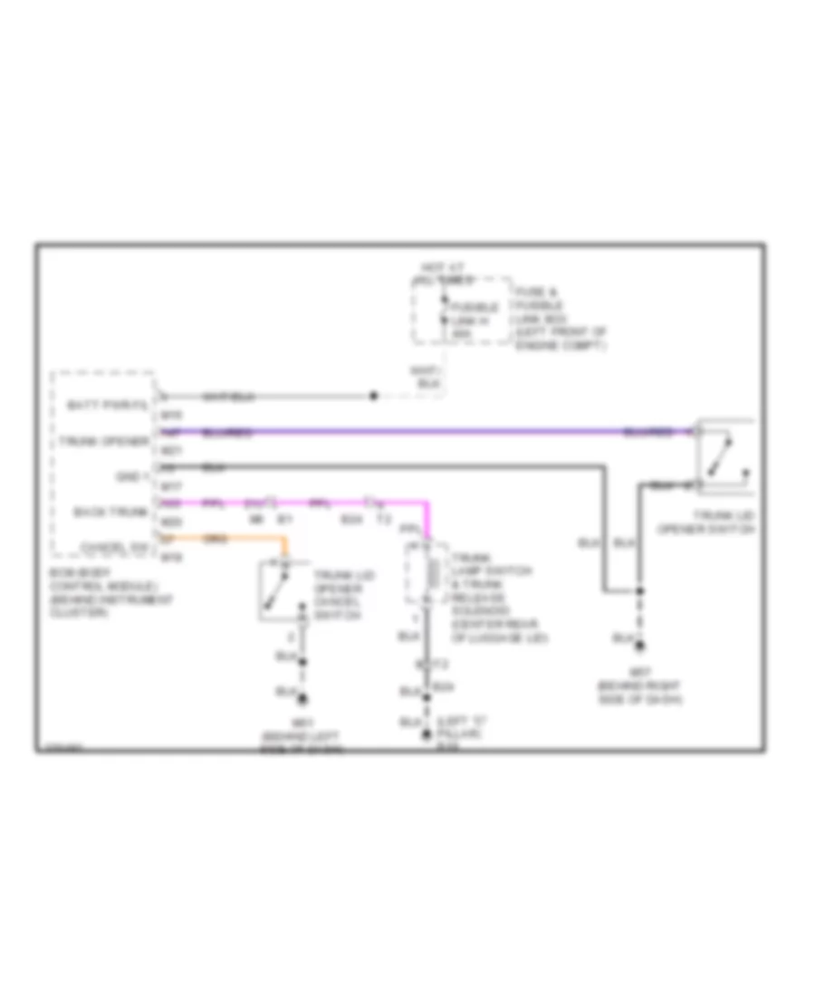
BODY CONTROL MODULES
Body Control Modules Wiring Diagram for Nissan Maxima SV 2012
List of elements for Body Control Modules Wiring Diagram for Nissan Maxima SV 2012:
- (behind right side of dash) m57
- A/l sig type 1
- Acc cont
- Acc led
- Air conditioning system
- As door ant a
- As door ant b
- As door sw 1
- As req sw
- At device out
- Back door ant a
- Back door ant b
- Back trunk opener
- Bat bcm fuse
- Batt (f/l)
- Bcm (body control module) (behind instrument cluster)
- Blower fan rly
- Brake sw 1
- Brake sw 2
- Buzzer
- Can h
- Can l
- Cdl back trunk
- Computer data lines system
- Cruise control system
- Defogger system
- Door lock status
- Door locks & anti-theft systems
- Door locks & power windows systems
- Door locks system
- Door unlk out
- Dr door ant a
- Dr door ant b
- Dr door sw
- Dr req sw
- Eng start sw
- Exterior lights system
- Exterior lights systems
- Fl flasher
- Fob in sw 1
- Fob reader clock
- Fob reader data
- Fob slot
- Fr flasher
- Fuse & fusible link box (left front of engine compt)
- Fuse 10a
- Fuse block (j/b) (lower left side of dash)
- Fusible link h 40a
- Gnd 1
- Gnd rf 2 a/l
- Hazard sw
- Headlights & exterior lights systems
- Headlights & warning systems
- Headlights system
- Headlights, door locks & anti-theft systems
- Hot at all times
- Hot w/ ignition relay 2 energized
- Ign f/b
- Ign on led
- Ign rel out 2
- Ign rly out
- Immo led
- Input 1
- Input 2
- Input 3
- Input 4
- Input 5
- Instrument cluster system
- Interior lights system
- Low side push
- M16
- M17
- M18
- M19
- M20
- M21
- Output 1
- Output 2
- Output 3
- Output 4
- Output 5
- P/w pwr sply
- Pnk
- Power distribution system
- Push button ignition switch
- Push switch
- Pw k line
- Rear def sw
- Rear defogger
- Red
- Rf 1 tuner sig
- Rf2 tuner sig
- Ring led
- Rl door sw
- Room ant 2 a
- Room ant 2 b
- Room lamp cont
- Rr door sw
- S/l lock led
- Seats, power tops & power windows systems
- Shift interlock system
- Shift n/p
- Shift p/ascd
- St rly out
- Starting/charging system
- Step lamp cont
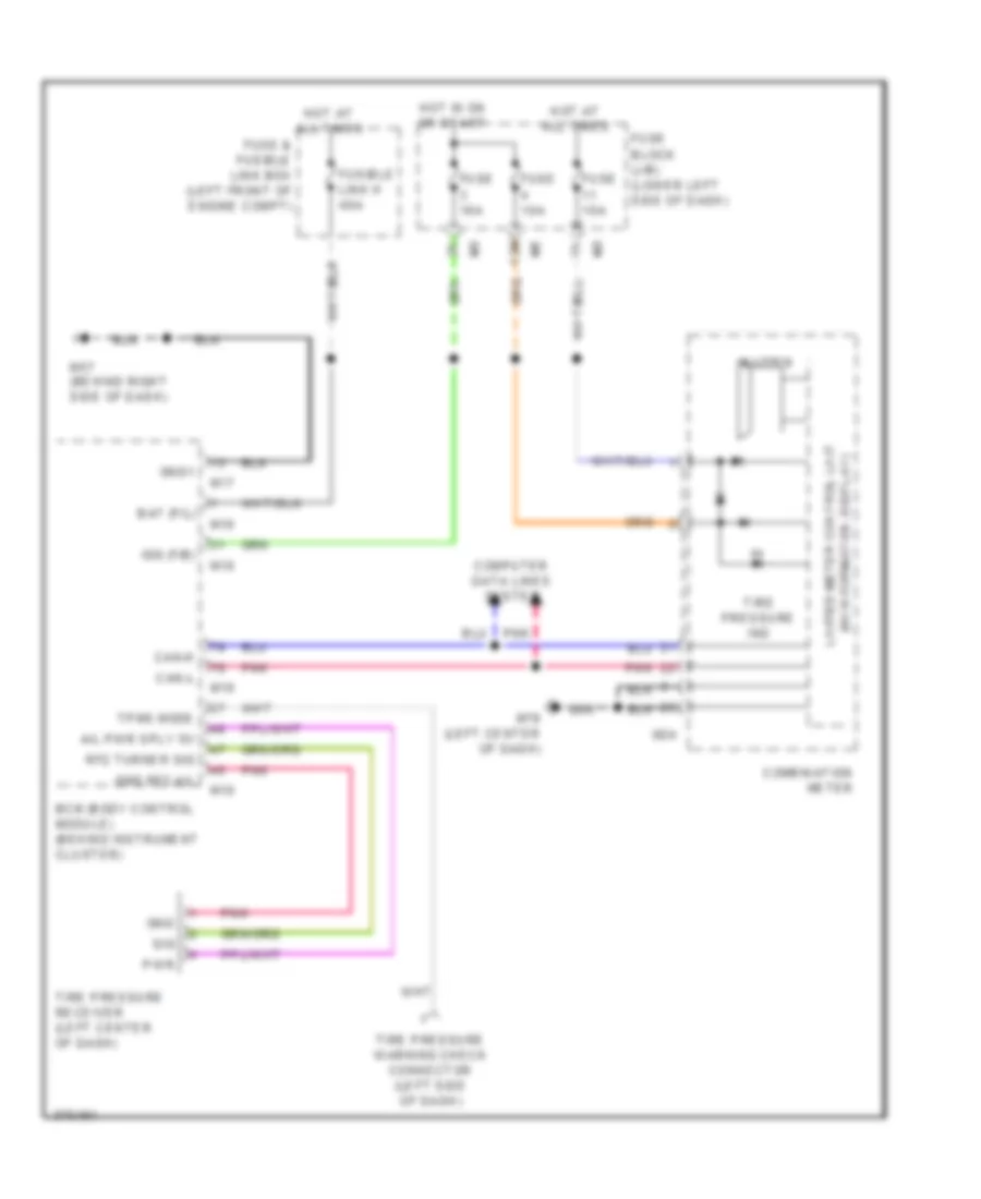
- Tpms mode
- Trunk ant 1 a
- Trunk ant 1 b
- Trunk cancel sw
- Trunk lamp output
- Trunk request sw
- Trunk sw
- Trunk, tailgate, fuel doors system
- Warning systems
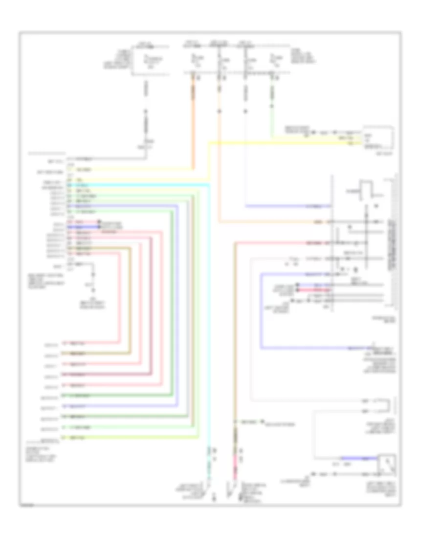
COMPUTER DATA LINES
Computer Data Lines Wiring Diagram for Nissan Maxima SV 2012
List of elements for Computer Data Lines Wiring Diagram for Nissan Maxima SV 2012:
- (on steering column) steering angle sensor
- 15g
- 15j
- 16j
- 34g
- 51g
- 52g
- 8g m1
- A/c & av switch assembly
- A/c auto amplifier
- Abs actuator & electric unit (control unit) (right rear corner of engine compt)
- Air bag diagnosis sensor unit (under rear of center console)
- Av control unit
- B10
- B125
- B208
- B32
- Bcm (body control module) (behind instrument cluster)
- Can h2
- Can l2
- Can-h
- Can-l
- Combination meter
- Connector (below left side of dash)
- Data link
- Driver's seat control unit (under driver's seat)
- E10
- E17
- E29
- E30
- E45
- E46
- Ecm (engine control module) (left front of engine compt)
- Fuse 10a
- Fuse block (j/b) (lower left side of dash)
- Hot at all times
- Hot in on or start
- Ipdm e/r (intelligent power distribution module engine room) (left side of engine compt)
- Joint connector b01 (near base of left "b" pillar)
- Joint connector e03 (left rear of engine compt)
- Joint connector e04 (left rear of engine compt)
- Junction block e45 & e46
- K-line
- M can h
- M can h trm
- M can l
- M can l trm
- M can2 h
- M can2 l
- M1 e30
- M110 b136
- M156
- M163
- M19
- M35
- M61 (behind left side of dash)
- Pnk
- Red
- Tcm (transmission control module) (left front of engine compt)
- W/ automatic drive positioner
- W/ navigation
- W/o automatic drive positioner
- W/o navigation
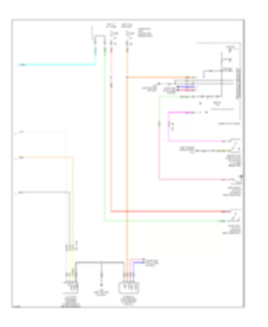
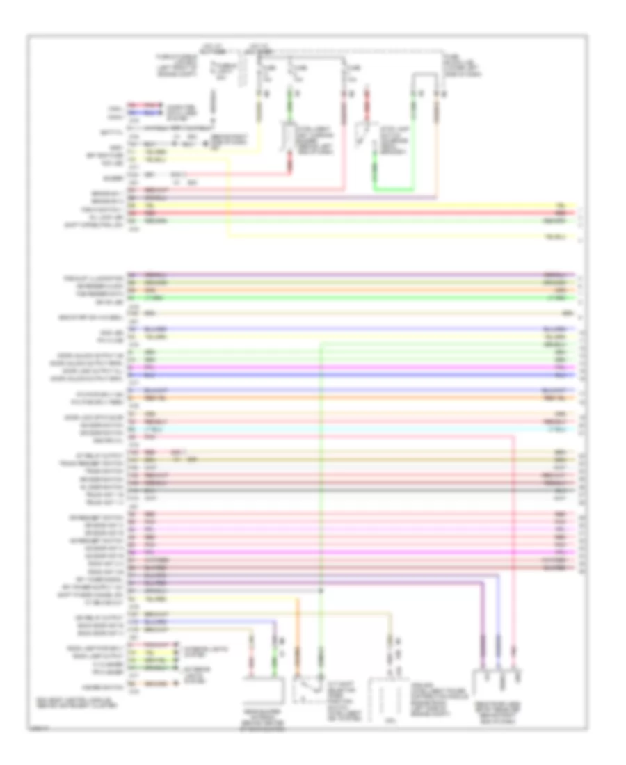
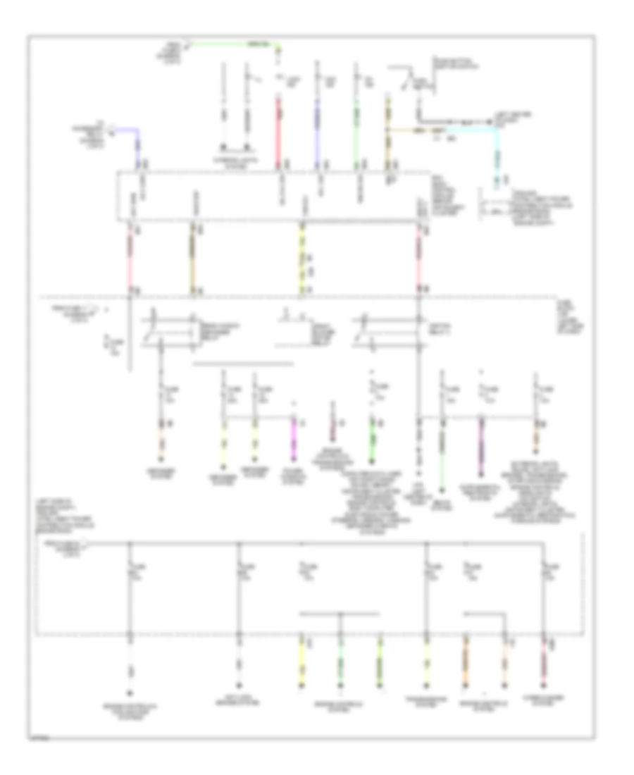
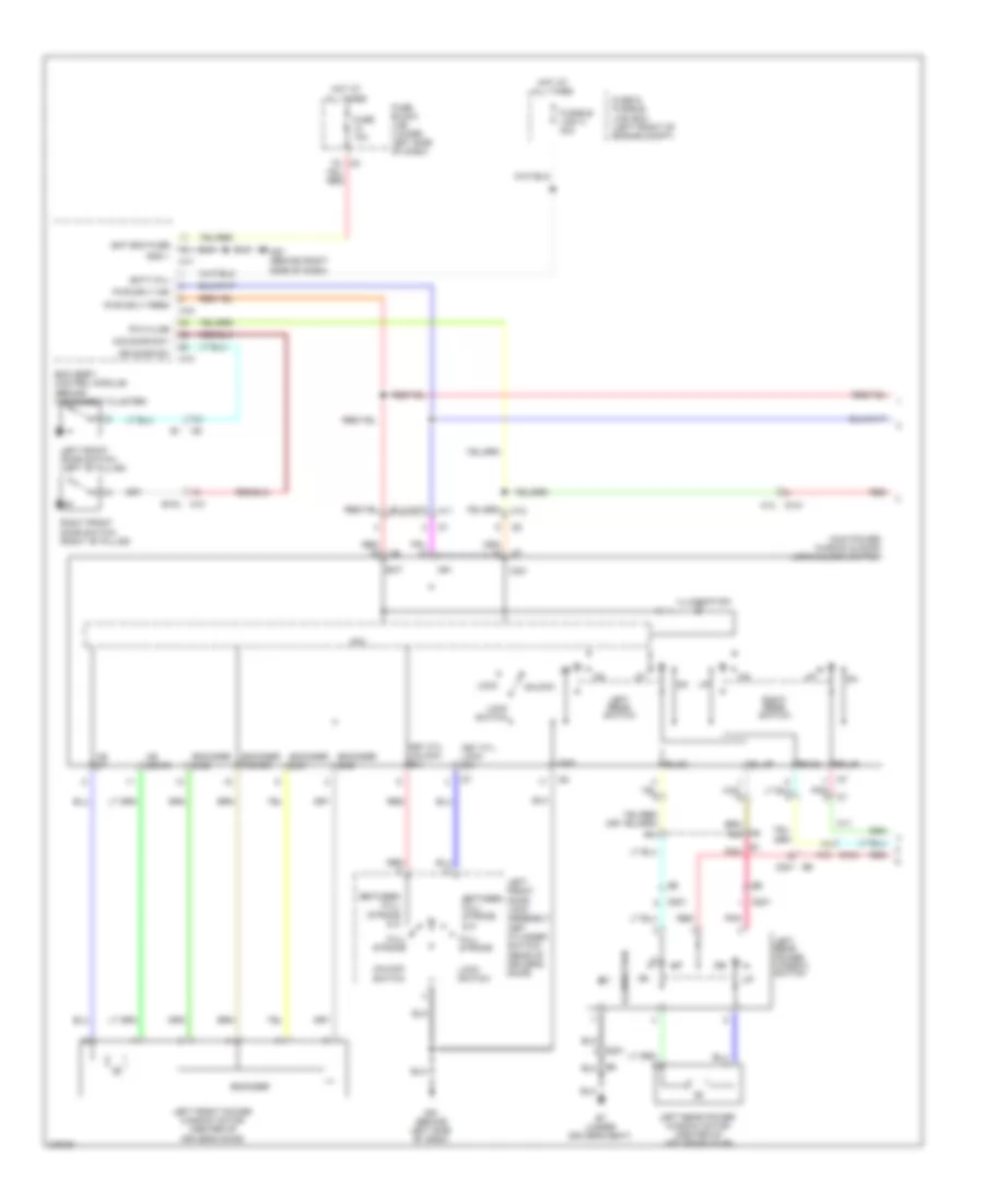
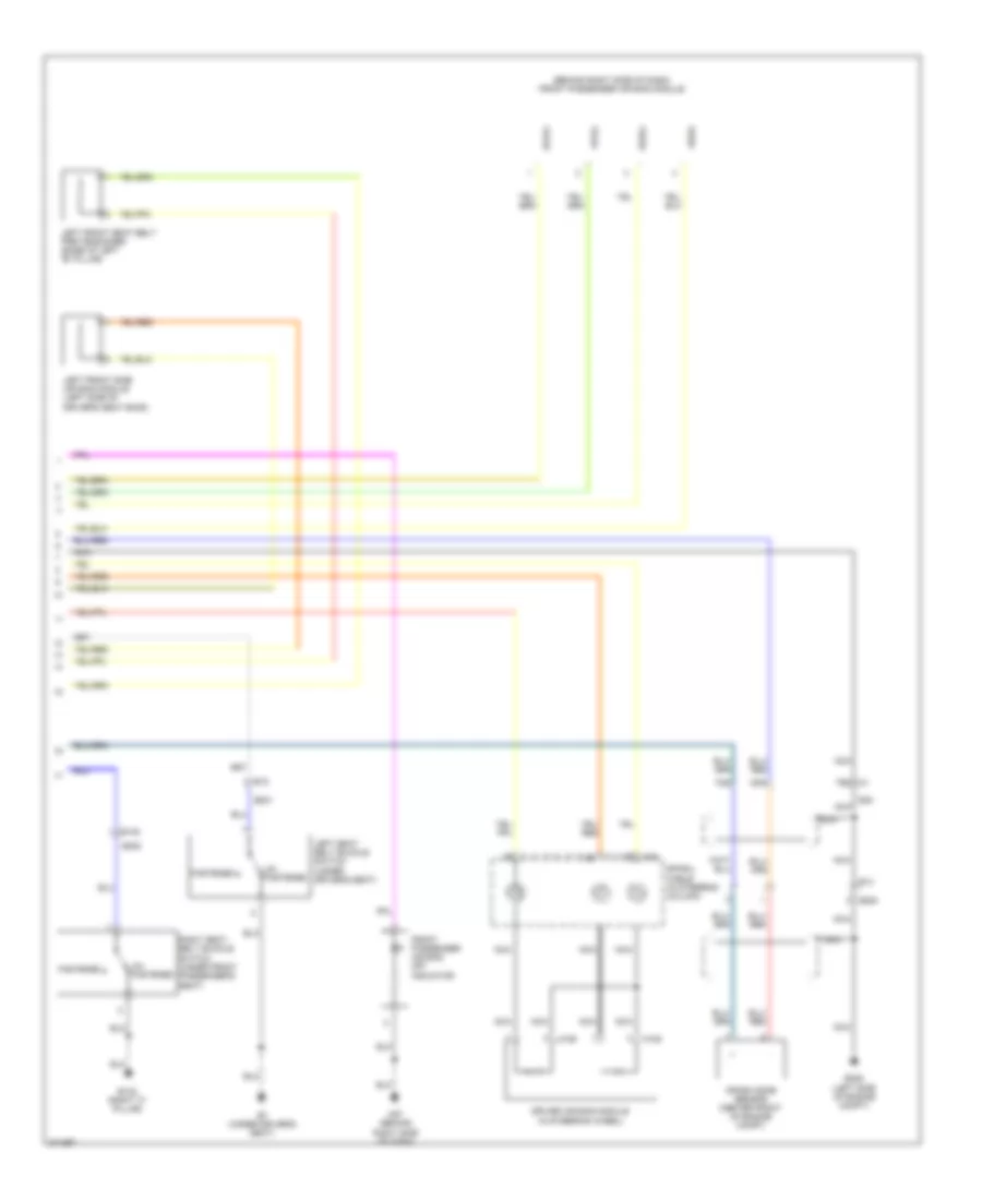
COOLING FAN
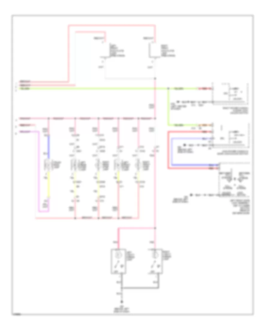
Cooling Fan Wiring Diagram for Nissan Maxima SV 2012
List of elements for Cooling Fan Wiring Diagram for Nissan Maxima SV 2012:
- A/c compressor (at left front of engine)
- A/c relay
- Avcc2
- Avcc2- pdpres
- Can-h
- Can-l
- Computer data lines system
- Cooling fan motor-1 (front of engine compt)
- Cooling fan motor-2 (front of engine compt)
- Cooling fan relay 1
- Cooling fan relay-2 (left side of engine compt)
- Cooling fan relay-3 (in fuse & fusible link box)
- Cpu
- E10
- E12
- E15 (left side of engine compt)
- E17
- E18
- E201
- E203
- E203 e12
- E209
- E44
- E45
- E47
- E48
- E9 (left rear of engine compt)
- Ecm (engine control module) (left front of engine compt)
- Engine coolant temperature sensor (left rear of engine)
- F1 e3
- F10
- F13
- F2 e11
- Fuse & fusible link box (left front of engine compt)
- Fuse 10a
- Fuse 15a
- Fusible link k 40a
- Fusible link m 40a
- Gnd
- Gnda-pdres
- Gnda-tw
- Hot at all times
- Hot in on or start
- Ignition relay 1
- Ipdm e/r (intelligent power distribution module engine room) (left side of engine compt)
- Joint connector-e01 (left side of engine compt)
- Joint connector-e02 (left rear of engine compt)
- Junction block e44 & e45
- Junction block e44, e47 & e48
- Motor fan rly hi
- Motor fan rly mid
- P-gnd
- Pdres
- Pnk
- Red
- Refrigerant pressure sensor (on a/c liquid tank)
- S-gnd
- Sig
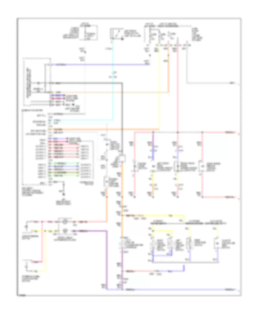
CRUISE CONTROL
Cruise Control Wiring Diagram for Nissan Maxima SV 2012
List of elements for Cruise Control Wiring Diagram for Nissan Maxima SV 2012:
- (left rear of engine compt) e9
- 12m
- 55g
- 58g
- Accel/res switch
- Accelerator pedal position sensor (on accelerator pedal bracket)
- Aps1
- Aps2
- Ascd brake switch (on brake pedal bracket)
- Ascd steering switch
- Ascdsw
- Avcc1-aps1
- Avcc1-tps-b1
- Avcc2-aps2
- Bncsw
- Brake
- Can-h
- Can-l
- Cancel switch
- Coast/set switch
- Combination meter
- Computer data lines system
- Cruise ind
- Cvt unit (left rear of engine)
- E10
- E11
- E30
- E44
- E45
- E46
- E9 (left rear of engine compt)
- Ecm (engine control module) (left front of engine compt)
- Electric throttle control actuator (on throttle body)
- F13
- F14
- Fuse 10a
- Fuse 10a f10
- Fuse block (j/b) (lower left side of dash)
- Gnd
- Gnda-aps1
- Gnda-aps2
- Gnda-ascdsw
- Gnda-tps-b1
- Hot at all times
- Hot in on or start
- Ipdm e/r (left side of engine compt)
- Junction block e44, e45 & e46
- Junction block e45 & e46
- M30
- M79 (left center of dash)
- M88
- Motor1-b1
- Motor2-b1
- On/off (main) switch
- Pnk
- Pri speed sens
- Pri speed sensor
- Primary speed sensor
- Red
- Sec spd sens
- Sec speed sens
- Secondary speed sensor (top of transaxle)
- Sens power source
- Sensor 1
- Sensor 2
- Sensor gnd
- Sns pwr source
- Spiral cable (in steering column)
- Stoplight switch (on brake pedal bracket)
- Tcm (left front of engine compt)
- Throttle control motor
- Throttle position sensor
- Tps1-b1
- Tps2-b1
- Unified meter control unit (w/ information display)
- Vign
DEFOGGERS
Defoggers Wiring Diagram for Nissan Maxima SV 2012
List of elements for Defoggers Wiring Diagram for Nissan Maxima SV 2012:
- (behind right side of dash) m57
- 10m m5
- 10t b4
- 11t
- 1s e7
- 2n m3
- 4q m4
- A/c auto amplifier (behind center of dash)
- A/c display unit (w/ monochrome display)
- A/c switch assembly
- B53
- B54
- B58 (right "c" pillar)
- Batt (f/l)
- Bcm (body control module) (behind instrument cluster)
- Can-h
- Can-l
- Computer data lines system
- D101
- D102
- E30
- Fuse & fusible link box (left front of engine compt)
- Fuse 10a
- Fuse 20a
- Fuse block (j/b) (lower left side of dash)
- Fusible link box (battery) (at battery)
- Fusible link c 100a
- Fusible link h 40a
- Gnd
- Gnd1
- Hot at all times
- Hot in on or start
- Ign
- Ign f/b
- Left door mirror (door mirror defogger) (w/ heated mirrors) (at mirror)
- M1 82g
- M11
- M12
- M14
- M15
- M16
- M17
- M18
- M19
- M57 (behind right side of dash)
- M61 (behind left side of dash)
- M79 (left center of dash)
- Pnk
- Rear window defogger
- Rear window defogger condenser (left "c" pillar)
- Rear window defogger relay
- Right door mirror (door mirror defogger) (w/ heated mirrors) (at mirror)
- Rr def on
- Rr def rly
- Rr def sw
- W/ monochrome display
- W/o monochrome display
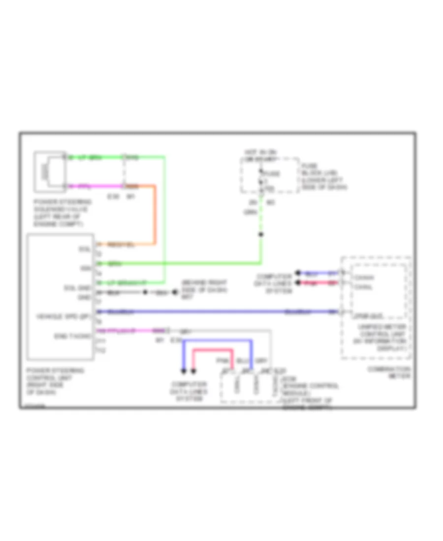
ELECTRONIC POWER STEERING
Electronic Power Steering Wiring Diagram for Nissan Maxima SV 2012
List of elements for Electronic Power Steering Wiring Diagram for Nissan Maxima SV 2012:
- (behind right side of dash) m57
- 2p/r out
- 60g
- 61g
- 62g
- Can-h
- Can-l
- Combination meter
- Computer data lines system
- E10
- E30
- E30 m1
- Ecm (engine control module) (left front of engine compt)
- Eng tacho
- Fuse 10a
- Fuse block (j/b) (lower left side of dash)
- Gnd
- Hot in on or start
- Ign
- Pnk
- Power steering control unit (right side of dash)
- Power steering solenoid valve (left rear of engine compt)
- Sol
- Sol gnd
- Tacho
- Unified meter control unit (w/ information display)
- Vehicle spd (2p)
ENGINE PERFORMANCE
3.5L
3.5L, Engine Performance Wiring Diagram (1 of 4) for Nissan Maxima SV 2012
List of elements for 3.5L, Engine Performance Wiring Diagram (1 of 4) for Nissan Maxima SV 2012:
- (1, 3 & 5: top of right cylinder bank) (2, 4 & 6: top of left cylinder bank) fuel injectors
- 12m
- Af+1
- Af+2
- Af-1
- Af-2
- Afh1
- Afh2
- Avcc1
- Avcc1-cursen,int
- Avcc1-pspres
- Avcc1-tps-b1
- Avcc2
- Battery current sensor
- Cursen
- E18
- E44
- E46
- E9 (left rear of engine compt)
- Ecm (engine control module) (left front of engine compt)
- Electronic controlled engine mount control solenoid valve
- Emmnv
- Engine coolant temperature sensor (left rear of engine)
- Engine oil temperature sensor (lower right front of engine)
- Enmn1
- Evap
- Evap canister purge volume control solenoid valve (top rear of engine)
- F13
- F14
- F2 e11
- Fpr
- Fuse 10a
- Fuse block (j/b) (lower left side of dash)
- Gnd
- Gnda-cursen,int
- Gnda-o2sr1, o2sr2
- Gnda-pdpres
- Gnda-pspres
- Gnda-tps-b1
- Gnda-tw,to1
- Hot in on or start
- Ign 1
- Ign 2
- Ign 3
- Ign 4
- Ign 5
- Ign 6
- Inj 1
- Inj 2
- Inj 3
- Inj 4
- Inj 5
- Inj 6
- Ipdm e/r (intelligent power distribution e201
- Junction block e44 & e46
- Module engine room) (left side of engine compt)
- Motor1-b1
- Motor2-b2
- Motrly-b1
- O2hr1
- O2hr2
- O2sr1
- O2sr2
- Output
- Pdpres
- Pnk
- Power steering pressure sensor (on power steering high pressure tube)
- Pspres
- Pwr
- Qa1-gnda-ta1
- Red
- Refrigerant pressure sensor (on a/c liquid tank)
- Sig
- Ssoff
- Ta1
- To1
- Tps1-b1
- Tps2-b1
- Vias 1
- Vias 2
- Vmot-b1
3.5L, Engine Performance Wiring Diagram (2 of 4) for Nissan Maxima SV 2012
List of elements for 3.5L, Engine Performance Wiring Diagram (2 of 4) for Nissan Maxima SV 2012:
- Combination meter
- Computer data lines system
- Condenser 2 (left rear of engine)
- E18
- E29 b10
- Ecm relay
- Electric throttle control actuator (on throttle body)
- F10
- F16 (left rear of engine)
- Fuel pump relay
- Fuse 15a
- Hot at all times
- Hot in on or start
- Ignition coils (w/ power transistor) (1, 3 & 5: top of right cylinder bank) (2, 4 & 6: top of left cylinder bank)
- Ipdm e/r (intelligent power distribution module engine room) (left side of engine compt)
- Loop wire
- M24
- M79 (left center of dash)
- Malfunction indicator lamp (mil)
- Nca
- Plug spark
- Pnk
- Red
- Sensor 1
- Sensor 2
- Spark plug
- Throttle control motor
- Throttle control motor relay
- Throttle positon sensor
- Unified meter control unit (w/ information display)
3.5L, Engine Performance Wiring Diagram (3 of 4) for Nissan Maxima SV 2012
List of elements for 3.5L, Engine Performance Wiring Diagram (3 of 4) for Nissan Maxima SV 2012:
- (left front of engine compt) tcm (transmission control module)
- Af (+)
- Af (-)
- Air/fuel ratio (a/f) sensor 1 (bank 1) (right side of engine)
- Air/fuel ratio (a/f) sensor 1 (bank 2) (left side of engine)
- Avcc1
- Avcc2
- Camshaft position sensor (phase) (bank 1) (rear of right cylinder head)
- Camshaft position sensor (phase) (bank 2) (rear of left cylinder head)
- Crankshaft position sensor (pos) (left rear of engine)
- E11
- E18
- E44
- E44 junction block e44 & e45 e45
- E45
- E9 (left rear of engine compt)
- Exhaust valve timing control position sensor (bank 1)
- Exhaust valve timing control position sensor (bank 2)
- F10
- Fuse 10a
- Fuse 15a
- Fuse block (j/b) (lower left side of dash)
- Gnd
- Heated oxygen sensor 2 (bank 1) (on right exhaust tube assembly)
- Heated oxygen sensor 2 (bank 2) (on left exhaust manifold)
- Heater (+)
- Heater (-)
- Hot at all times
- Hot in on or start
- Intake air temperature sensor
- Ipdm e/r (intelligent power distribution module engine room) (left side of engine compt)
- Junction block e44 & e45
- Mass airflow sensor (on intake air duct)
- Nca
- Output
- Phase
- Pnk
- Pos
- Pwr
- Red
- Sens (+)
- Sens (-)
- St rly
- Stop light switch (on brake pedal bracket)
3.5L, Engine Performance Wiring Diagram (4 of 4) for Nissan Maxima SV 2012
List of elements for 3.5L, Engine Performance Wiring Diagram (4 of 4) for Nissan Maxima SV 2012:
- (front of left cylinder head) intake valve timing control solenoid valve (bank 1)
- (in fuel tank) fuel level sensor unit & fuel pump
- (top left side of engine) vias control solenoid valve (bank 1)
- (top right rear of engine) vias control solenoid valve (bank 2)
- 30j
- 63g
- Accelerator pedal position sensor
- Aps1
- Aps2
- Ascdsw
- Avcc & e phase 1
- Avcc & e phase 2
- Avcc 1 & e phase1
- Avcc1-aps1
- Avcc2-aps2
- Avcc2-ftpres
- Avcc2-pdpres
- Avcc2-pos
- B10
- B42
- B7 (under driver's seat)
- Batt
- Bncsw
- Brake
- Can-h
- Can-l
- Cdcv
- Computer data lines system
- Cruise control system
- Cvtc 1
- Cvtc 2
- E phase 1
- E-phase 2
- E10
- E11
- E29
- E30
- E45
- E50
- E9 (left rear of engine compt)
- Ecm (engine control module) (left front of engine compt)
- Electronic power steering system
- Evap canister vent control valve (on evap canister)
- Evap control system pressure sensor (under left
- Evtc 1
- Evtc 2
- Exhaust valve timing control magnet retarder (bank 1) (left rear of engine)
- Exhaust valve timing control magnet retarder (bank 2) (left front of engine)
- F13
- F201
- F69
- Ftpres
- Fuel pump
- Fuel tank temper- ature sensor
- Gnd
- Gnd-pos
- Gnda-aps1
- Gnda-aps2
- Gnda-ascdsw
- Gnda-ftpres
- Gnda-knk1, knk2
- Gnda-tf
- Ignsw
- Intake valve timing control solenoid valve (bank 2) (front of right cylinder head)
- Junction block
- Junction block e44 & e45 e44
- Kline
- Knk
- Knk1
- Knk2
- Knock sensor (bank 1) (top of cylinder block)
- Knock sensor (bank 2) (top of cylinder block)
- Neut-h
- Phase 1
- Phase 2
- Pnk
- Pos
- Ptpres
- Pwr
- Qa1+
- Rear of vehicle)
- Red
- Sensor 1
- Sensor 2
- Shield
- Tacho (cabin)
- Vbr
EXTERIOR LIGHTS
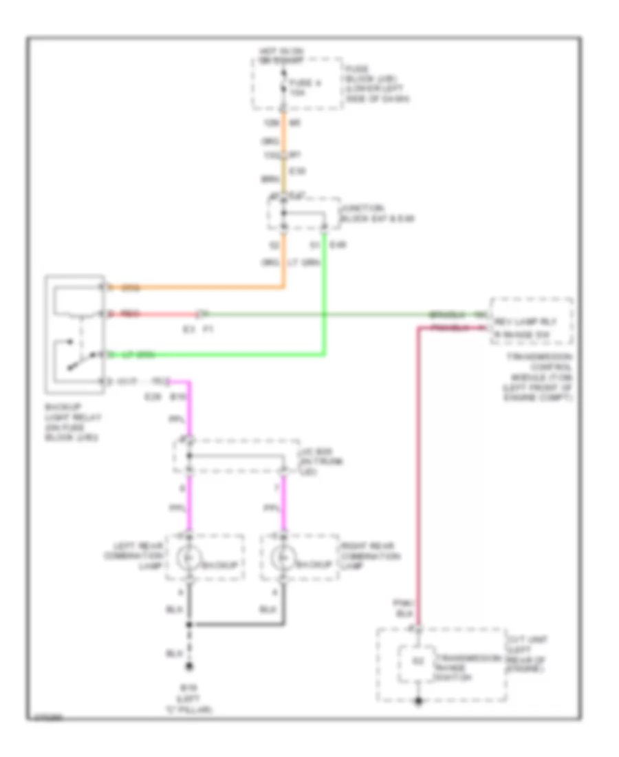
Backup Lamps Wiring Diagram for Nissan Maxima SV 2012
List of elements for Backup Lamps Wiring Diagram for Nissan Maxima SV 2012:
- (left "c" pillar)
- 12m m5
- B19
- Backup
- Backup light relay (on fuse block (j/b))
- Cvt unit (left rear of engine)
- E29 b10
- E30
- E47
- E49
- Fuse 4 10a
- Fuse block (j/b) (lower left side of dash)
- Hot in on or start
- J/c b05 (in trunk lid)
- Junction block e47 & e49
- Left rear combination lamp
- M1 13g
- R range sw
- Red
- Rev lamp rly
- Right rear combination lamp
- Transmission control module (tcm) (left front of engine compt)
- Transmission range switch
Exterior Lamps Wiring Diagram (1 of 2) for Nissan Maxima SV 2012
List of elements for Exterior Lamps Wiring Diagram (1 of 2) for Nissan Maxima SV 2012:
- (behind right side of dash) m57
- (left side of engine compt)
- As door sw
- B19 (left "c" pillar)
- B28
- B500
- Bat (f/l)
- Bat bcm fuse
- Body control module (bcm) (behind instrument cluster)
- Can-h
- Can-l
- Combination switch
- Computer data lines system
- Cpu
- D101
- D102
- Dr door sw
- E15 (left side of engine compt)
- E16
- E17
- E18
- E201
- E202
- E204
- E209
- E30
- Fl flasher
- Fr flasher
- Fuse & fusible link box (left front of engine compt)
- Fuse 10a
- Fuse 15a
- Fusible link box (battery) (at battery)
- Fusible link d 60a
- Fusible link h 40a
- Gnd1
- Hazard sw
- Hazard switch
- High mounted stop lamp
- Hot at all times
- Input 1
- Input 2
- Input 3
- Input 4
- Input 5
- Interior lights system
- Ipdm e/r (intelligent power distribution module engine room) (left side of engine compt)
- M14
- M15
- M16
- M17
- M18
- M19
- M21
- M6 3j
- M79 (left center of dash)
- Nca
- Output 1
- Output 2
- Output 3
- Output 4
- Output 5
- Park
- Pnk
- Right door mirror (w/ turn signal in mirror) (at mirror)
- Right front combination lamp
- Right rear combination lamp
- Rl door sw
- Rr door sw
- Side marker
- Stop
- Tail
- Tail lamp relay
- Turn signal
- W/ rear sunshade
Exterior Lamps Wiring Diagram (2 of 2) for Nissan Maxima SV 2012
List of elements for Exterior Lamps Wiring Diagram (2 of 2) for Nissan Maxima SV 2012:
- (w/ information display)
- 12m m5
- 8p e6
- B19 (left "c" pillar)
- B24
- Combination meter
- Computer data lines system
- E202
- E204 (left side of engine compt)
- E209
- E30
- Fuse 10a
- Fuse block (j/b) (lower left side of dash)
- High mounted stop lamp (w/ rear spoiler)
- Hot at all times
- Hot in on or start
- J/c b05 (in trunk lid)
- Left door mirror (w/ turn signal in mirror) (at mirror)
- Left front combination lamp
- Left license plate lamp
- Left rear combination lamp
- Left turn ind
- M1 1g
- M11
- M3 1n
- M6 4j
- M61 (behind left side of dash)
- M79 (left center of dash)
- Park
- Pnk
- Red
- Right license plate lamp
- Right turn ind
- Side marker
- Stop
- Stop light switch (on brake pedal bracket)
- Tail
- Turn signal
- Unified meter control unit
GROUND DISTRIBUTION
Ground Distribution Wiring Diagram for Nissan Maxima SV 2012
List of elements for Ground Distribution Wiring Diagram for Nissan Maxima SV 2012:
- Abs actuator & electric unit (control unit)
- Air bag diagnosis sensor unit shield
- Air bag diagnosis sensor unit shield & left side air bag (satellite sensor)
- Air bag diagnosis sensor unit shield & right side air bag (satellite) sensor shield
- B114
- B127
- B132 (right "c" pillar)
- B19 (left "c" pillar)
- B5 (under driver's seat)
- B55 (rear parcel shelf)
- B58 (right "c" pillar)
- B7 (under driver's seat)
- Bcm (body control module), front passenger air bag off indicator, a/c auto amp, adp steering switch, key slot, av control unit (base w/ color display), power steering control unit, automatic drive positioner control unit, glove box lamp, trunk lid opener switch, display unit, a/c display unit (w/ monocrome display), a/c switch assembly (w/ monocrome display), aux in jack shield, (bose w/ color display), intake door motor, mode door motor, driver side air mix door motor, passenger side air mix door motor, right front outside handle av control unit shield (bose w/ color display) & fuse block (j/b)
- Data link connector, combination switch, blower motor, climate controlled seat relay (if equipped), trunk lid opener cancel switch, vdc off switch, heated steering wheel switch, door mirror remote control switch, left vanity mirror lamp, auto anti-dazzling inside mirror, sunroof switch, right vanity mirror lamp, sunroof motor assembly, sunshade motor assembly (w/ dual panel sunroof), left door mirror, main power window & door lock/unlock switch, left front door lock assembly, seat memory switch, left front outside handle & left rear personal lamp
- E15 (left side of engine compt)
- E204 (left side of engine compt)
- E206 (left side of engine compt)
- E209
- E229 (right front of engine compt)
- E33 (right rear of engine compt)
- E9 (left rear of engine compt)
- Ecm, cooling fan relay 2, air fuel ratio (a/f) sensor 1 (bank 1) shield, electric throttle control actuator shield & air fuel ratio (a/f) sensor 1 (bank 2) shield
- F16 (left rear of engine)
- F9 (left front of engine)
- Fuse block (j/b), combination meter, spiral cable, air bag diagnosis sensor unit, push-button ignition switch (push switch), steering angle sensor, hazard switch, yaw rate/side/decel g sensor, a/c & av switch assembly (bose w/ color display), cvt shift selector, paddle shifter (shift up), paddle shifter (shift down), front power socket, front console power socket, right front heated seat switch (w/ climate controlled seat), left front heated seat switch, (w/o climate controlled seat), climate controlled seat switch (if equipped), rear sunshade switch, right power window & door lock/unlock switch, right door mirror & accessory relay 2 (late production)
- Generator
- Ignition coils 1, 2, 3, 4, 5 & 6 (w/ power transistor) & condenser 2
- Ipdm e/r (intelligent power distribution module engine room), brake fluid level switch, front wiper motor, shift lock relay, cooling fan relay 3, a/c compressor & tcm (transmission control module)
- Joint connector mo2 (left side of dash)
- Left front combination lamp (w/ xenon headlamp), cooling fan motor 2, right front combination lamp (w/o xenon headlamp) & right front fog lamp
- Left reclining motor, left front power seat, left seat belt buckle switch, fuel level sensor unit & fuel pump, left power seat switch, left front seat heater (w/o climate controlled seat), lumbar support switch, climate controlled seat control unit (if equipped), driver seat control unit & left rear power window switch
- Left side curtain air bag shield (early production)
- M57 (behind right side of dash)
- M61 (behind left side of dash)
- M79 (left center of dash)
- Nca
- Rear window defogger
- Right side air bag module shield (early production)
- Subwoofer amp (w/ base audio), left rear combination lamp, high mounted stop lamp, right rear combination lamp, trunk opener request switch, left license plate lamp, trunk lamp switch & trunk release solenoid, right license plate lamp, high mounted stop lamp shield & rear sun shade unit
- Washer level switch, left front fog lamp left front combination lamp, daytime light relay & right front combination lamp
HEADLIGHTS
Headlights Wiring Diagram (1 of 2) for Nissan Maxima SV 2012
List of elements for Headlights Wiring Diagram (1 of 2) for Nissan Maxima SV 2012:
- 12m
- 24g
- 28j
- A/l signal
- As door sw
- B104
- Bat (f/l)
- Bat bcm fuse
- Body control module (bcm) (behind instrument cluster)
- Brake ind
- Can-h
- Can-l
- Combination meter
- Combination switch (lighting & turn signal switch)
- Computer data lines system
- Dr door sw
- E30
- Fuse & fusible link box (left front of engine compt)
- Fuse 10a
- Fuse block (j/b) (lower left side of dash)
- Fusible link h 40a
- Gnd
- Gnd 1
- High beam ind
- Hot at all times
- Hot in on or start
- Input 1
- Input 2
- Input 3
- Input 4
- Input 5
- Left rear door switch (left "c" pillar)
- M10
- M16
- M17
- M18
- M19
- M21
- M57 (behind right side of dash)
- M79 (left center of dash)
- Optical sensor (top right side of dash)
- Output
- Output 1
- Output 2
- Output 3
- Output 4
- Output 5
- Park brake switch (on brake pedal bracket)
- Pkb
- Pnk
- Pwr
- Right rear door switch (right "c" pillar)
- Rl door sw
- Rr door sw
- Unified meter control unit (w/ infor- mation display)
Headlights Wiring Diagram (2 of 2) for Nissan Maxima SV 2012
List of elements for Headlights Wiring Diagram (2 of 2) for Nissan Maxima SV 2012:
- (left side of engine compt) (w/ halogen) e204 e209 (w/ xenon)
- (left side of engine compt) (w/ xenon) e204 e209 (w/ halogen)
- 10j
- B104
- Computer data lines system
- Cpu
- Daytime light relay (w/ drl)
- E15 (left side of engine compt)
- E16
- E17
- E18
- E200
- E201
- E202
- E204 (left side of engine compt)
- E209
- E212
- E213
- E222
- E223
- E231
- E232
- E233
- Front fog lamp relay
- Fuse 10a
- Fuse 15a
- Fusible link box (battery) (at battery)
- Fusible link d 60a
- Headlamp high
- Headlamp high relay
- Headlamp low
- Headlamp low relay
- Hid cont
- Hot at all times
- Hot in on or start
- Ipdm e/r (intelligent power distribution module engine room) (left side of engine compt)
- Left front combination lamp (headlamp)
- Left front door switch (left "b" pillar)
- Left front fog lamp
- M10
- Pnk
- Right front combination lamp (headlamp)
- Right front door switch (right "b" pillar)
- Right front fog lamp
- W/ drl
- W/ halogen
- W/ halogen w/o drl
- W/ xenon
- W/ xenon w/o drl
- W/o drl
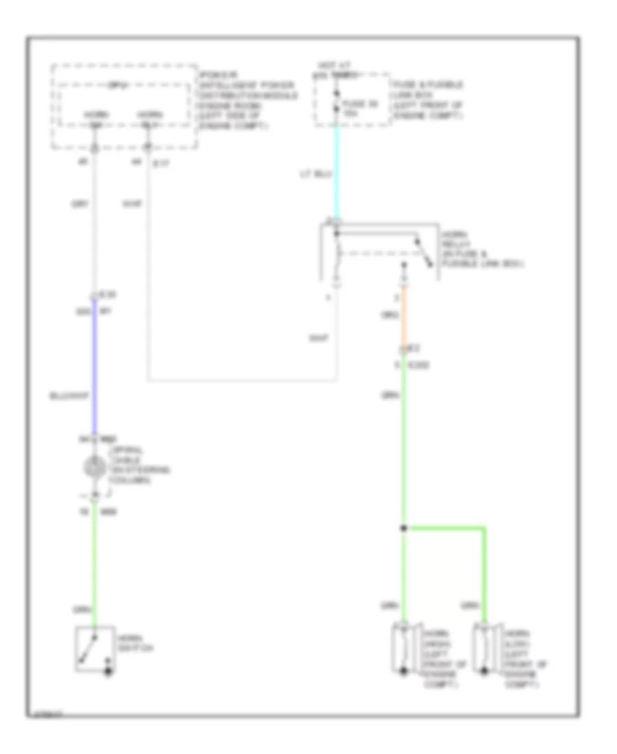
HORN
Horn Wiring Diagram for Nissan Maxima SV 2012
List of elements for Horn Wiring Diagram for Nissan Maxima SV 2012:
- Cpu
- E17
- E202
- E30
- Fuse & fusible link box (left front of engine compt)
- Fuse 30 15a
- Horn (high) (left front of engine compt)
- Horn (low) (left front of engine compt)
- Horn relay (in fuse & fusible link box)
- Horn rly
- Horn sw
- Horn switch
- Hot at all times
- Ipdm e/r (intelligent power distribution module engine room) (left side of engine compt)
- M1 30g
- M30
- M88
- Spiral cable (in steering column)
INSTRUMENT CLUSTER
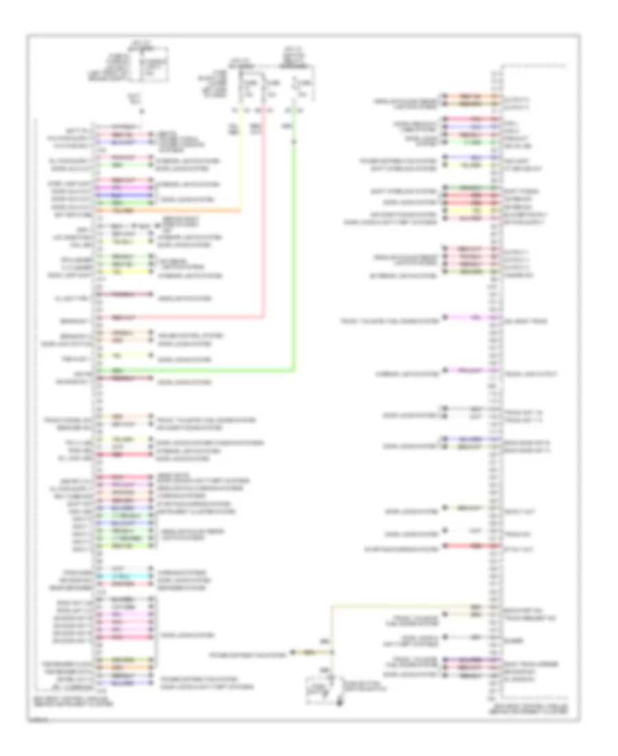
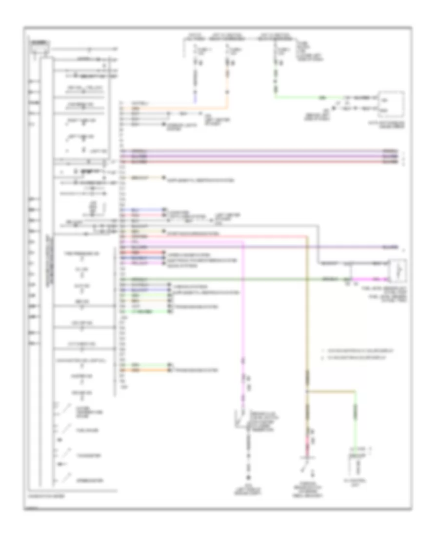
Instrument Cluster Wiring Diagram (1 of 2) for Nissan Maxima SV 2012
List of elements for Instrument Cluster Wiring Diagram (1 of 2) for Nissan Maxima SV 2012:
- (left center of dash) m79
- 12m
- 24g
- 29j
- 30j
- 31g
- Abs ind
- Air bag ind
- Auto anti-dazzling inside mirror
- Av control unit
- Belt ind
- Brake fluid level switch (on master cylinder reservoir)
- Brake ind
- Buzzer
- Charge ind
- Combination meter
- Computer data lines system
- Cruise ind
- Cvt check ind
- E15 (left side of engine compt)
- E30
- Electronic power steering system
- Fuel gauge
- Fuel level sensor unit & fuel pump (fuel level sensor) (in fuel tank)
- Fuse 11 10a
- Fuse 3 10a
- Fuse 4 10a
- Fuse block (j/b) (lower left side of dash)
- Gnd
- High beam ind
- Hot at all times
- Hot w/ ignition relay 2 energized
- Ign
- Interior lights system
- Key ind
- Left turn ind
- Light ind
- M156
- M163
- M23
- M24
- M61 (behind left side of dash)
- M79 (left center of dash)
- Malfunction ind lamp (mil)
- Master ind
- Meter illum
- Oil ind
- Parking brake switch (on brake pedal bracket)
- Pkb sig
- Pnk
- Red
- Right turn ind
- Security ind
- Slip ind
- Sound systems
- Speedometer
- Starting/charging system
- Tachometer
- Tire pressure ind
- Transmissions system
- Unified meter control unit (w/ information display)
- Vdc off ind
- W/ navigation & color display
- W/o navigation & w/ color display
- Warning systems
- Water temperature gauge
- Wiper/washer system
Instrument Cluster Wiring Diagram (2 of 2) for Nissan Maxima SV 2012
List of elements for Instrument Cluster Wiring Diagram (2 of 2) for Nissan Maxima SV 2012:
- 10j
- 26j
- 28j
- As door sw
- B19 (left "c" pillar)
- B24 t2
- Bcm (body control module) (behind instrument cluster)
- Can-h
- Can-l
- Computer data lines system
- Cpu
- Dr door sw
- E17
- F10
- Gnd 1
- Immo led
- Interior lights system
- Ipdm e/r (intelligent power distribution module engine room) (left side of engine compt)
- Left front door switch (left "b" pillar)
- Left rear door switch (left "c" pillar)
- M10 b104
- M17
- M18
- M19
- M21
- M57 (behind right side of dash)
- M6 b1
- Meter mode switch
- Mode a switch
- Mode b switch
- Oil pres
- Oil pressure switch (lower left front of engine)
- Pnk
- Right front door switch (right "b" pillar)
- Right rear door switch (right "c" pillar)
- Rl door sw
- Rr door sw
- Trunk lamp switch & trunk release solenoid (trunk release solenoid: center rear of luggage lid)
- Trunk sw
INTERIOR LIGHTS
Courtesy Lamps Wiring Diagram (1 of 2) for Nissan Maxima SV 2012
List of elements for Courtesy Lamps Wiring Diagram (1 of 2) for Nissan Maxima SV 2012:
- 10j
- 26j
- 28j
- As door sw 1
- B104
- B19 (left "c" pillar)
- B24
- Bat (f/l)
- Bat bcm fuse
- Body control module (bcm) (behind instrument cluster)
- Can-h
- Can-l
- Computer data lines system
- Door
- Dr door sw
- Fob slot illumination
- Front room/map lamp assembly
- Fuse & fusible link box (left front of engine compt)
- Fuse 10a
- Fuse block (j/b) (lower left side of dash)
- Fusible link h 40a
- Gnd 1
- Hot at all times
- Instrument illumination circuit
- Interior room lamp switch
- Key slot
- Left foot lamp
- Left front door switch (left "b" pillar)
- Left front room/map lamp
- Left rear door switch (left "c" pillar)
- Left rear personal lamp
- Light bat (+) light a gnd
- M10
- M16
- M17
- M18
- M19
- M20
- M21
- M57 (behind right side of dash)
- M61 (behind left side of dash)
- Nca
- Off
- Pnk
- Pw k-line
- Right foot lamp
- Right front door switch (right "b" pillar)
- Right front room/map lamp
- Right rear door switch (right "c" pillar)
- Right rear personal lamp
- Rl door sw
- Room lamp cont
- Rr door sw
- Step lamp cont
- Trunk lamp cont
- Trunk lid switch & trunk release solenoid (center rear of luggage lid)
- Trunk sw
Courtesy Lamps Wiring Diagram (2 of 2) for Nissan Maxima SV 2012
List of elements for Courtesy Lamps Wiring Diagram (2 of 2) for Nissan Maxima SV 2012:
- 22j
- 23j
- B104
- B134
- Between full stroke & n
- Cpu
- D102
- D201
- D306
- Full stroke
- Left front door lock assembly (key cylinder switch) (rear of driver's door)
- Left front kick plate lamp (pre-wiring)
- Left front step lamp
- Left rear step lamp
- Left vanity mirror lamp
- Lock
- Lock switch
- M10
- M11
- M12
- M14
- M15
- M6 5j
- M6 6j
- M61 (behind left side of dash)
- M79 (left center of dash)
- Main power window & door lock/unlock switch
- Off
- Pnk
- Red
- Right front kick plate lamp (pre-wiring)
- Right front step lamp
- Right power window & door lock/ unlock switch
- Right rear step lamp
- Right vanity mirror lamp
- Trunk room lamp
- Unlock
- Unlock switch
Instrument Illumination Wiring Diagram (1 of 2) for Nissan Maxima SV 2012
List of elements for Instrument Illumination Wiring Diagram (1 of 2) for Nissan Maxima SV 2012:
- Ascd steering switch
- Bat (f/l)
- Bat bcm fuse
- Bcm (body control module) (behind instrument cluster)
- Can-h
- Can-l
- Climate controlled seat switch
- Combination meter
- Combination switch
- Computer data lines system
- Cvt device (under center console)
- D101
- Diode 3 (left center of dash)
- Door mirror remote control switch
- Dr door sw
- E6 9p
- Fuse & fusible link box (left front of engine compt)
- Fuse 10a
- Fuse block (j/b) (lower left side of dash)
- Fusible link h 40a
- Gnd 1
- Hot at all times
- Hot w/ ignition relay 2 energized
- Input 1
- Input 2
- Input 3
- Input 4
- Input 5
- J/c m01 (left side of dash)
- Left front door inside handle illumination
- Left front door switch (left "b" pillar)
- Left front heated seat switch
- Low side push led
- M12
- M14
- M16
- M17
- M18
- M19
- M203
- M205
- M208
- M29
- M3 7n
- M30
- M305
- M4 8q
- M5 12m
- M57 (behind right side of dash)
- M6 10j
- M79 (left center of dash)
- M87
- M88
- Meter ill ind
- Meter mode switch
- Output 1
- Output 2
- Output 3
- Output 4
- Output 5
- Pnk
- Push- button ignition switch
- Rear sunshade switch
- Right front door inside handle illumination
- Right front heated seat switch
- Ring led
- Spiral cable (in steering column)
- Steering wheel audio control switch
- Unified meter control unit (w/ information display)
- W/ climate controlled seats
- W/ front heated seats
- W/ power rear sunshade
Instrument Illumination Wiring Diagram (2 of 2) for Nissan Maxima SV 2012
List of elements for Instrument Illumination Wiring Diagram (2 of 2) for Nissan Maxima SV 2012:
- A/c & a/v switch assembly (w/ color display)
- A/c display unit (w/ monochrome display)
- A/c switch assembly (w/ monochrome display)
- Audio unit
- Av control unit (w/ color display)
- Can-h
- Can-l
- Computer data lines system
- Cont
- Cpu
- Display unit (w/ monochrome display)
- E15 (left side of engine compt)
- E16
- E17
- E18
- Front room/map lamp assembly
- Fuse 10a
- Fuse 15a
- Fusible link box (battery) (at battery)
- Fusible link d 60a
- Glove box lamp
- Gnd
- Hazard switch
- Heated steering wheel switch (if equipped)
- Hot at all times
- Ill
- Ill+
- Ill-
- Ipdm e/r (intelligent power distribution module engine room) (left side of engine compt)
- M132
- M133
- M152
- M160
- M57 (behind right side of dash)
- P-gnd
- Pnk
- S-gnd
- Tail lamp relay
- Vdc off switch
- W/ base
- W/ bose
- W/ navigation
- W/o navigation
MEMORY SYSTEMS
Memory Systems Wiring Diagram (1 of 3) for Nissan Maxima SV 2012
List of elements for Memory Systems Wiring Diagram (1 of 3) for Nissan Maxima SV 2012:
- (behind left side of dash) m61
- 10j
- 82g
- Adp steering switch
- Automatic drive positioner control unit (behind right center of dash)
- Backward
- Bat
- Bat (f/l)
- Bat bcm fuse
- Bcm (body control module) (behind instrument cluster)
- Can-h
- Can-l
- Change over switch
- Circuit breaker (behind left side of dash)
- Computer data lines system
- Door mirror remote control switch
- Down
- Downward
- Dr door sw
- E30
- Forward
- Fuse & fusible link box (left front of engine compt)
- Fuse 10a
- Fuse block (j/b) (lower left side of dash)
- Fusible link h 40a
- Gnd
- Gnd1
- Hot at all times
- Hot in on or start
- Ign f/b
- Interior lights system
- Left front door switch (left "b" pillar)
- Leftward
- Lh mir mtr
- Lh mir sns
- Lh mit mtr
- Lh select
- M16
- M17
- M18
- M19
- M3 7n
- M57 (behind right side of dash)
- M63
- M67
- Mirror switch
- Pnk
- Red
- Rh mir mtr
- Rh mir sns
- Rh select
- Rightward
- Sns gnd
- Sns pwr
- Strg sns vcc
- Telescopic switch
- Tilt motor (on steering column)
- Tilt switch
- Uart
- Up/fwd
- Upward
Memory Systems Wiring Diagram (2 of 3) for Nissan Maxima SV 2012
List of elements for Memory Systems Wiring Diagram (2 of 3) for Nissan Maxima SV 2012:
- (at mirror) left door mirror
- (at mirror) right door mirror
- Backward
- D1 m11
- D102 m15
- D2 m12
- Forward
- Ind 1
- Ind 2
- M12
- M61 (behind left side of dash)
- Off
- Pnk
- Red
- Seat memory switch
- Set
- Sw 1
- Sw 2
- Telescopic motor (on steering column)
Memory Systems Wiring Diagram (3 of 3) for Nissan Maxima SV 2012
List of elements for Memory Systems Wiring Diagram (3 of 3) for Nissan Maxima SV 2012:
- 20j
- 49j
- 50j
- 51j
- 52j
- 53j
- 54j
- 56j
- 57j
- Address 1
- Address 2
- B1 m6
- B201 b12
- B203
- B205
- B206
- B208
- B211
- B32
- B7 (under driver's seat)
- Backward
- Bat (ptc)
- Bwd
- Can-h
- Can-l
- Computer data lines system
- Driver's seat control unit (under driver's seat)
- Forward
- Fr lift sw up
- Front lift mtr up
- Front lift sw dwn
- Front lifting
- Front lifting motor
- Frt lift mtr dwn
- Fwd
- Gnd
- Ind 1
- Ind 2
- Left front power seat (under driver's seat)
- Left power seat switch
- Left reclining motor (under driver's seat)
- Lumbar support motor (in driver's seat back)
- Lumbar support switch
- M12
- Nca
- Pnk
- Pulse front lift
- Pulse rear lift
- Pulse recliner
- Pulse slide
- Pulse telescopic
- Pulse tilt
- Pwr sply encoder
- Rear lift mtr dwn
- Rear lift mtr up
- Rear lift sw dwn
- Rear lift sw up
- Rear lifting motor
- Recliner mtr back
- Recliner mtr fwd
- Recliner sw back
- Recliner sw fwd
- Reclining switch
- Red
- Set sw
- Slide mtr back
- Slide mtr fwd
- Slide sw back
- Slide sw fwd
- Sliding motor
- Sliding switch
- Switch
- Switch lifting rear
- Uart tx/rx
NAVIGATION
Navigation Wiring Diagram (1 of 3) for Nissan Maxima SV 2012
List of elements for Navigation Wiring Diagram (1 of 3) for Nissan Maxima SV 2012:
- 54g
- 64g
- 88j
- Acc
- Amp on
- Av control unit
- B (+)
- Bat
- Can h
- Can l
- Comp (+)
- Comp (-)
- Comp1 shield
- Comp1 sync
- Computer data lines system
- Disp it
- Display unit
- E30
- Fuse & fusible link box (left front of engine compt)
- Fuse 10a
- Fuse 15a
- Fuse block (j/b) (lower left side of dash)
- Gnd
- Gvif (+)
- Gvif (-)
- Hot at all times
- Hot in on or acc
- Hot in on or start
- Ign
- Ill
- Interior lights system
- It disp
- Lf pre +
- Lf pre -
- Lr pre +
- Lr pre -
- M can h
- M can l
- M can trm
- M1 53g
- M112
- M142
- M151
- M160
- M161
- M163
- M167
- M210
- M57 (behind right side of dash)
- M7 r1
- Mic gen
- Mic gnd
- Mic sig
- Mic vcc
- Microphone (center front of roof)
- Mr out
- Navi comp1 (+)
- Navi comp1 (-)
- Navigation system
- Pkb sig
- Pnk
- Red
- Reverse sig
- Rf pre +
- Rf pre -
- Rr pre +
- Rr pre -
- Shield
- Shield comp
- Spd sig
- Strg sw a
- Strg sw b
- Strg sw gnd
- Sync comp
- Usb d +
- Usb d+
- Usb d-
- Usb gnd
- Usb interface
- V bus
- Vbus
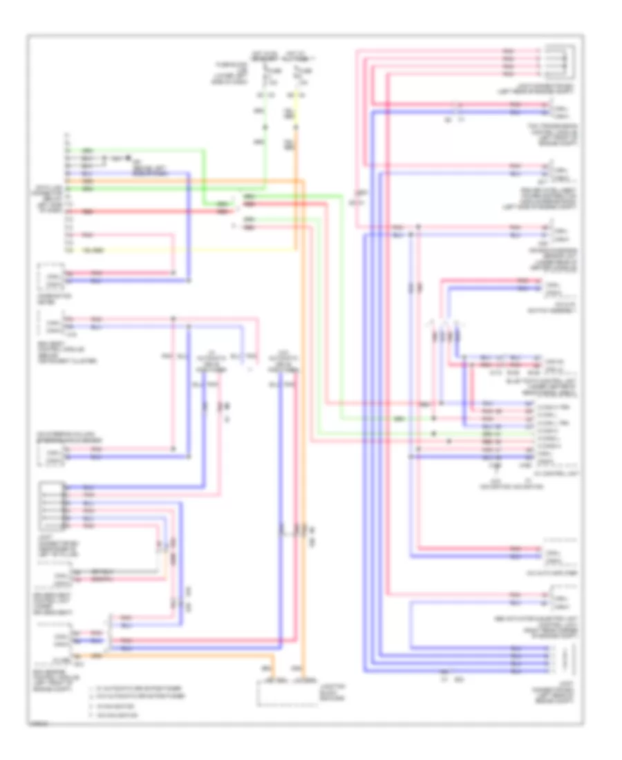
Navigation Wiring Diagram (2 of 3) for Nissan Maxima SV 2012
List of elements for Navigation Wiring Diagram (2 of 3) for Nissan Maxima SV 2012:
- (on brake pedal bracket) park brake switch
- 24g
- 80j
- 81j
- B103
- B134
- Back
- Combination meter
- Computer data lines system
- D201
- D306
- Display)
- Down menu
- Down volume
- E30
- Enter
- J/c b05 (in trunk lid)
- Left front door speaker
- Left rear door speaker
- Left rear subwoofer
- Left tweeter
- M11
- M30
- M8 b102
- M88
- Phone
- Pnk
- Red
- Right rear door speaker
- Right rear subwoofer
- Right tweeter
- Source
- Spiral cable (in steering column)
- Steering wheel audio control switches
- System lights exterior
- Unified meter control unit (w/ infor -mation
- Up menu
- Up volume
Navigation Wiring Diagram (3 of 3) for Nissan Maxima SV 2012
List of elements for Navigation Wiring Diagram (3 of 3) for Nissan Maxima SV 2012:
- A/c & av switch assembly
- Acc
- Amp on
- Ant b+
- Ant main
- Antenna amplifier
- Aux gnd
- Aux in jack
- Aux shield
- Aux video +
- Aux video -
- Av control unit
- B103
- B109
- B110
- B132 (right "c" pillar)
- Batt
- Bose speaker amplifier (under rear parcel shelf)
- Camera gnd
- Camera v+
- Can h
- Can l
- Cd eject
- Center speaker
- Comp out (+)
- Comp out (-)
- Computer data lines system
- D101
- Gnd
- Gps ant
- Gps antenna
- Ill (+)
- Ill cont gnd
- Interior lights system
- Lf door out (+)
- Lf door out (-)
- Lf in (+)
- Lf in (-)
- Lf twdr out (+)
- Lf twdr out (-)
- Lh aux audio (+)
- Lh woofer out (+)
- Lh woofer out (-)
- Lr door out (+)
- Lr door out (-)
- Lr in (+)
- Lr in (-)
- M103
- M14
- M162
- M164
- M165
- M166
- M168
- M200
- M57 (behind right side of dash)
- M59
- M79 (left center of dash)
- M85
- Navigation system
- Nca
- Pnk
- Red
- Rf door out (+)
- Rf door out (-)
- Rf in (+)
- Rf in (-)
- Rf twdr out (+)
- Rf twdr out (-)
- Rh aux audio (+)
- Rh woofer out (+)
- Rh woofer out (-)
- Right front door speaker
- Rr door out (+)
- Rr door out (-)
- Rr in (+)
- Rr in (-)
- Satellite antenna
- Shield
- Sw gnd
- Twdr out (+)
- Twdr out (-)
- Video shield
- Window antenna
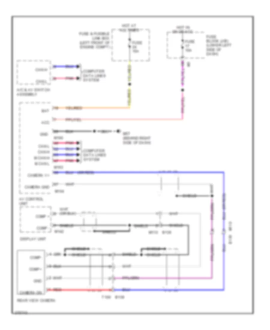
Rear Camera Wiring Diagram, with Navigation for Nissan Maxima SV 2012
List of elements for Rear Camera Wiring Diagram, with Navigation for Nissan Maxima SV 2012:
- (or red)
- A/c & av switch assembly
- Acc
- Av control unit
- Bat
- Camera gnd
- Camera on
- Camera v+
- Can h
- Can l
- Comp +
- Comp -
- Comp+
- Comp-
- Computer data lines system
- Display unit
- Fuse & fusible link box (left front of engine compt)
- Fuse 10a
- Fuse 15a
- Fuse block (j/b) (lower left side of dash)
- Gnd
- Hot at all times
- Hot in on or acc
- M can h
- M can l
- M110 b136
- M142
- M160
- M163
- M164
- M57 (behind right side of dash)
- Pnk
- Rear view camera
- Red
- Shield
- T100 b139
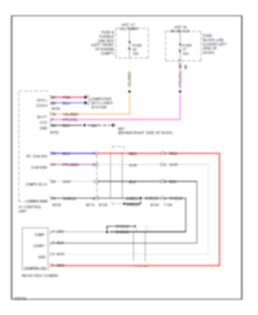
Rear Camera Wiring Diagram, without Navigation for Nissan Maxima SV 2012
List of elements for Rear Camera Wiring Diagram, without Navigation for Nissan Maxima SV 2012:
- Acc
- Av control unit
- B139
- Batt
- Cam gnd
- Camera on
- Can h
- Can l
- Comp+
- Comp-
- Comp2 gnd
- Comp2 in (+)
- Computer data lines system
- Fuse & fusible link box (left front of engine compt)
- Fuse 10a
- Fuse 15a
- Fuse block (j/b) (lower left side of dash)
- Gnd
- Hot at all times
- Hot in on or acc
- M110 b136
- M152
- M155
- M156
- M57 (behind right side of dash)
- Pnk
- Rear view camera
- Red
- Rv cam sig
- Shield
- T100
POWER DISTRIBUTION
Power Distribution Wiring Diagram (1 of 3) for Nissan Maxima SV 2012
List of elements for Power Distribution Wiring Diagram (1 of 3) for Nissan Maxima SV 2012:
- (at battery) fusible link box (battery)
- (left front of engine compt) fuse & fusible link box
- (left side of engine compt) ipdm e/r (intelligent power distribution module engine room)
- 82g
- Anti-lock brakes system
- Battery
- Circuit breaker (behind left side of dash)
- Cpu
- E16
- E18
- E201
- E30
- Ecm relay
- Engine controls system
- Exterior lights system
- Exterior lights, defogger, interior lights, headlights, seats, memory, wiper/washer, trunk, tailgate, fuel doors, power tops, anti-theft, body computer, door locks, warning & power windows systems
- F10
- Front fog lamp relay
- Fuse 10a
- Fuse 15a
- Fuse 30a
- Fusible link a 250a
- Fusible link b 80a
- Fusible link c 100a
- Fusible link d 60a
- Fusible link e 100a
- Fusible link f 50a
- Fusible link g 30a
- Fusible link h 40a
- Fusible link k 40a
- Fusible link l 40a
- Fusible link m 40a
- Headlamp high relay
- Headlamp low relay
- Headlights system
- Headlights, interior lights & exterior lights systems
- Horns, anti-theft & door locks systems
- Joint connector e01 (left side of engine compt)
- Navigation, air conditioning & sound systems
- Pnk
- Red
- Seats & memory systems
- Seats system
- Sound & navigation systems
- Starting/ charging system
- Tail lamp relay
- Throttle control motor relay
- To cpu (diagram 2 of 3)
- To front wiper relay (diagram 2 of 3)
- To fuse 5 (diagram 2 of 3)
- To starter relay (diagram 2 of 3)
- W/ bose audio system
- W/ heated steering wheel
Power Distribution Wiring Diagram (2 of 3) for Nissan Maxima SV 2012
List of elements for Power Distribution Wiring Diagram (2 of 3) for Nissan Maxima SV 2012:
- (left side of engine compt) ipdm e/r (intelligent power distribution module engine room)
- (lower left side of dash) fuse block (j/b)
- 11p
- 12p
- A/c relay
- Accessory relay
- Accessory relay (late production)
- Air conditioning, body computer, sound, memory, mirrors, defogger & navigation systems
- Anti-theft, door locks, body computer, memory, power tops, power windows & warning systems
- Body computer, door locks, anti-lock brakes, transmissions, engine controls, anti-theft & exterior lights systems
- Cooling fan relay 1
- Cpu
- Door locks & body computer systems
- E15 (left side of engine compt)
- E17
- E18
- Early production
- From bcm (body control module) (diagram 3 of 3)
- From fuse 43 (diagram 1 of 3)
- From fuse 55 (diagram 1 of 3)
- From fusible link c (diagram 1 of 3)
- From joint connector e01 (diagram 1 of 3)
- Front console power socket
- Front power socket
- Front wiper high relay
- Front wiper relay
- Fuel pump relay
- Fuse 10a
- Fuse 15a
- Fuse 20a
- Ignition relay 1
- Interior lights, door locks, body computer & anti-theft systems
- Late production
- M205
- M79 (left center of dash)
- M87
- Red
- Sound systems
- Sound, transmissions, engine controls, air conditioning, computer data lines, navigation & mirrors systems
- Starter relay
- To fuse 10 (diagram 3 of 3)
- To fuse 33 (diagram 3 of 3)
- To push button ignition switch (diagram 3 of 3)
- Transmissions system
Power Distribution Wiring Diagram (3 of 3) for Nissan Maxima SV 2012
List of elements for Power Distribution Wiring Diagram (3 of 3) for Nissan Maxima SV 2012:
- (left center of dash) m79
- (left side of engine compt) ipdm e/r (intelligent power distribution module engine room)
- 10m
- 10t
- 11m
- 11t
- 12m
- 23g
- 29g
- Acc ind
- Acc led
- Anti-lock brakes system
- Bat bcm
- Bcm (body control module) (behind instrument cluster)
- Computer data lines, air conditioning, sound, memory, instrument cluster, transmissions, engine controls, body computer, electronic power steering, mirrors, warning, defogger & seats systems
- Cpu
- Defogger system
- E18
- E200
- E30
- Eng
- Engine controls & cooling fans systems
- Engine controls & transmissions systems
- Engine controls system
- F10
- Fan rly
- From fuse 11 d (diagram 2 of 3)
- From fuse 32 f (diagram 2 of 3)
- From g fuse 9 (diagram 2 of 3)
- Front blower motor relay
- Fuse 10a
- Fuse 15a
- Fuse 20a
- Fuse block (j/b) (lower left side of dash)
- Ign on led
- Ign rly out 2
- Ignition relay 2
- Ill
- Interior lights system
- Ipdm e/r (intelligent power distribution module engine room) (left side of engine compt)
- Lock ind
- M17
- M18
- M19
- M19 acc cont
- M21
- M79 (left center of dash)
- On ind
- Pnk
- Power windows system
- Push button ignition switch
- Push switch
- Rear def
- Rear window defogger relay
- Red
- S/l lck led
- Seats system
- To accessory relay (diagram 2 of 3)
- Transmissions system
- Wiper/washer system
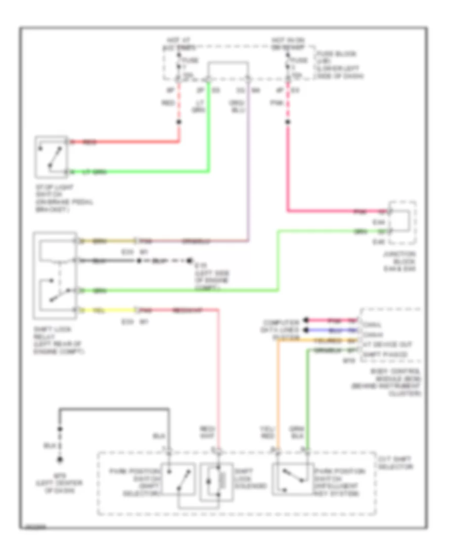
POWER DOOR LOCKS
Power Door Locks Wiring Diagram (1 of 4) for Nissan Maxima SV 2012
List of elements for Power Door Locks Wiring Diagram (1 of 4) for Nissan Maxima SV 2012:
- (behind right side of dash) m57
- 11p
- 12v
- 13j
- 14j
- 20g
- 27g
- 57g
- 82g
- Acc led
- As door ant a
- As door ant b
- As door switch
- As request switch
- At device out
- Back door ant a
- Back door ant b
- Bat bcm fuse
- Batt f/l
- Bcm (body control module) (behind instrument cluster)
- Brake sw 1
- Brake sw 2
- Buzzer
- Can-h
- Can-l
- Computer data lines system
- Cpu
- Cvt shift selector (park position) switch (intelligent key system)
- Door lock output all
- Door lock status dr
- Door unlock output as
- Door unlock output dr/fl
- Door unlock output rr/rl
- Dr door ant a
- Dr door ant b
- Dr door switch
- Dr request switch
- E18
- E30
- Eng start sw w/o escl
- Exterior lights system
- Fl flasher
- Fob in switch 1
- Fob reader data
- Fob slot illumination
- Fr flasher
- Fuse & fusible link box (left front of engine compt)
- Fuse 10a
- Fuse block (j/b) (lower left side of dash)
- Fusible link h 40a
- Gnd
- Gnd rf2 a/l
- Gnd1
- Hazard switch
- Hot at all times
- Ign on led
- Ign relay output
- Immo led
- Intelligent key warning buzzer (behind left end of dash)
- Interior lights system
- Ipdm e/r (intelligent power distribution module engine room) (left side of engine compt)
- M16
- M17
- M18
- M19
- M21
- Ob reader clock
- P/w pwr sply ign
- P/w pwr sply perm
- Pnk
- Pw k-line
- Rear bumper antenna (behind center of rear bumper)
- Red
- Remote keyless entry receiver (behind right end of dash)
- Rf1 tuner signal
- Rl door switch
- Room ant 2 a
- Room ant 2 b
- Room lamp output
- Room lamp pwr sply
- Rr door switch
- S/l lock led
- Shift n/p/neutral sw
- Shift p/ascd cancel sw
- Signal
- St relay output
- Stop lamp switch (on brake pedal bracket)
- Trunk ant 1 a
- Trunk ant 1 b
- Trunk request switch
- Trunk switch
Power Door Locks Wiring Diagram (2 of 4) for Nissan Maxima SV 2012
List of elements for Power Door Locks Wiring Diagram (2 of 4) for Nissan Maxima SV 2012:
- (left side of engine compt) e15
- 11j
- 12j
- 19g
- 28j
- 29g
- Computer data lines system
- Cpu
- D101
- D102
- D106
- D115
- D15
- E16
- E17
- E18
- E30
- F10
- Front console antenna (behind center of dash)
- Fuse & fusible link box (left front of engine compt)
- Fusible link b 80a
- Fusible link box (battery) (at battery)
- Fusible link l 40a
- Headlamp high relay
- Headlamp low relay
- Headlights system
- Horns system
- Hot at all times
- Ignition relay 1
- Ipdm e/r (intelligent power distribution module engine room) (left side of engine compt)
- J/c e01 (left side of engine compt)
- Left front outside handle
- Left rear door switch (left "c" pillar)
- M12
- M14
- M15
- M57 (behind right side of dash)
- M61 (behind left side of dash)
- Outside key antenna
- Pnk
- Rear parcel shelf antenna (under center of rear parcel shelf)
- Red
- Request switch
- Right front outside handle
- Starter control relay
- Starter relay
- Starting/ charging system
Power Door Locks Wiring Diagram (3 of 4) for Nissan Maxima SV 2012
List of elements for Power Door Locks Wiring Diagram (3 of 4) for Nissan Maxima SV 2012:
- (right "b" pillar)
- 10j
- 26j
- 27j
- 33g
- B104
- B19 (left "c" pillar)
- B24
- E30
- E46
- E50
- Fuse 10a
- Fuse block (j/b) (lower left side of dash)
- Fusible link box (battery) (at battery)
- Fusible link d 60a
- Hot at all times
- Junction block e46 & e50
- Left front door switch (left "b" pillar)
- M10
- Red
- Right front door switch
- Right rear door switch (right "c" pillar)
- St rly
- Tcm (transmission control module) (left front of engine compt)
- Trunk lid switch & trunk release solenoid (trunk lamp switch) (center rear of luggage compt lid)
- Trunk opener request switch
Power Door Locks Wiring Diagram (4 of 4) for Nissan Maxima SV 2012
List of elements for Power Door Locks Wiring Diagram (4 of 4) for Nissan Maxima SV 2012:
- 96j
- 97j
- Acc ind
- Actuator
- B104
- B134 d306
- Between full stroke & n
- Buzzer
- Card switch 1
- Clock
- Combination meter
- Computer data lines system
- Cpu
- D101
- D201
- Data
- Door unlock sensor
- Fuel lid door lock actuator (left side of luggage compt)
- Full stroke
- Gnd
- J/c b05 (in trunk lid)
- Key cylinder switch
- Key ind
- Key slot
- Left front door lock assembly (rear of driver's door)
- Left rear door lock actuator (rear of left rear door)
- Light a
- Light bat+
- Lock
- Lock ind
- Lock switch
- M10
- M11
- M12
- M14
- M14 d101
- M57 (behind right side of dash)
- M61 (behind left side of dash)
- M79 (left center of dash)
- Main power window & door lock/unlock switch
- On ind
- Pnk
- Push button ignition switch
- Push switch
- Red
- Right front door lock actuator (rear of front passenger's door)
- Right power window & door lock/unlock switch
- Right rear door lock actuator (rear of right rear door)
- Security ind
- Unified meter control unit (w/ information display)
- Unlock
- Unlock switch
POWER MIRRORS
Auto Anti-dazzling Inside Mirror Wiring Diagram, with Homelink Universal Transceiver for Nissan Maxima SV 2012
List of elements for Auto Anti-dazzling Inside Mirror Wiring Diagram, with Homelink Universal Transceiver for Nissan Maxima SV 2012:
- 6q m4
- Auto anti-dazzling inside mirror
- Bat+
- Ec+
- Ec-
- Fuse 10a
- Fuse block (j/b) (lower left side of dash)
- Gnd
- Hot at all times
- Hot in on or start
- Ign
- Left door mirror (at mirror)
- M12
- M3 2n
- M61 (behind left side of dash)
- Oec+
- Oec-
Auto Anti-dazzling Inside Mirror Wiring Diagram, without Homelink Universal Transceiver for Nissan Maxima SV 2012
List of elements for Auto Anti-dazzling Inside Mirror Wiring Diagram, without Homelink Universal Transceiver for Nissan Maxima SV 2012:
- (behind left side of dash) m61
- Auto anti-dazzling inside mirror
- Fuse 10a
- Fuse block (j/b) (lower left side of dash)
- Gnd
- Hot in on or start
- Ign
Power Mirrors Wiring Diagram for Nissan Maxima SV 2012
List of elements for Power Mirrors Wiring Diagram for Nissan Maxima SV 2012:
- Auto anti-dazzling inside mirror circuit
- Change over switch
- Defogger
- Defogger system
- Door mirror remote control switch
- Ec+
- Ec-
- Exterior lights system
- Fuse 17 10a
- Fuse block (j/b) (lower left side of dash)
- Hot in acc or on
- Illumination
- Interior lights system
- Left door mirror (at mirror)
- M12 d2
- M15 d102
- M61 (behind left side of dash)
- Mirror switch
- Off
- Pnk
- Right door mirror (at mirror)
- Turn signal
POWER SEATS
Climate Control Seats Wiring Diagram for Nissan Maxima SV 2012
List of elements for Climate Control Seats Wiring Diagram for Nissan Maxima SV 2012:
- 20j
- 58j
- 59j
- 60j
- 61j
- 81g
- 98j
- 99j
- B12 b201
- B201 b12
- B208
- B212
- B216
- B217
- B32
- B32 b208
- B7 (under driver's seat)
- Back sens gnd
- Back sens sig
- Back ted 1
- Back ted 2
- Bat (ptc)
- Blower gnd
- Blower power
- Blwr mtr spd ctrl
- Circuit breaker (behind left side of dash)
- Climate control seat blower motor (under driver's seat)
- Climate control seat control unit (under driver's seat)
- Climate controlled seat relay (left side of dash)
- Climate controlled seat switch
- Cool
- Cool ind
- Cool on ind
- Cool sw input
- Cushion sens gnd
- Cushion sens sig
- Cushion ted1
- Cushion ted2
- E30
- Fuse & fusible link box (left front of engine compt)
- Fuse 10a
- Fuse 15a
- Fuse block j/b (lower left side of dash)
- Fusible link h 40a
- Gnd
- Heat
- Heat ind
- Heat on ind
- Heat sw input
- Hot at all times
- Hot in on or start
- Ign
- Illumination
- Interior lights system
- M208 m305
- M6 b1
- M61 (behind left side of dash)
- M79 (left center of dash)
- M85 m200
- Mid
- Nca
- Off
- Pnk
- Red
- Resistor pwr
- Seat back thermal electric device
- Seat cushion thermal electric device
- Sensor
- Ted
Heated Seats Wiring Diagram for Nissan Maxima SV 2012
List of elements for Heated Seats Wiring Diagram for Nissan Maxima SV 2012:
- 19j
- 8m m5
- B104
- B12
- B132 (right "c" pillar)
- B148
- B201
- B308
- B7 (under driver's seat)
- Fuse 15a
- Fuse block (j/b) (lower left side of dash)
- Heater
- High
- Hot in on or start
- Illum
- Interior lights system
- Left front heated seat switch (w/o climate controlled seat)
- Left front seat heater
- Low
- M10
- M205
- M208
- M305
- M6 18j
- M79 (left center of dash)
- M87
- Off
- Pnk
- Right front heated seat switch
- Right front seat heater
- Thermostat
- W/ memory
- W/o memory
Heated Steering Wheel Wiring Diagram for Nissan Maxima SV 2012
List of elements for Heated Steering Wheel Wiring Diagram for Nissan Maxima SV 2012:
- Cpu
- E30
- Fuse & fusible link box (left front of engine compt)
- Fuse 10a
- Fuse block (j/b) (lower left side of dash)
- Heated steering relay (on fuse block (j/b))
- Heated steering wheel
- Heated steering wheel switch
- Hot at all times
- Hot in on or start
- Illum
- Interior lights system
- M1 83g
- M3 2n
- M61 (behind left side of dash)
- M79 (left center of dash)
- Off
- On ind
- Spiral cable (in steering column)
Lumbar Wiring Diagram for Nissan Maxima SV 2012
List of elements for Lumbar Wiring Diagram for Nissan Maxima SV 2012:
- (behind instrument cluster) bcm (body control module)
- (behind right side of dash) m57
- 20j
- B1 m6
- B12 b201
- B7 (under driver's seat)
- Back- ward
- Backward
- Batt (f/l)
- For- ward
- Forward
- Fuse & fusible link box (left front of engine compt)
- Fusible link h 40a
- Gnd
- Hot at all times
- Lumbar support motor (in driver's seat back)
- Lumbar support switch
- M17
- P/w pwr sply perm m16
Power Seat Wiring Diagram for Nissan Maxima SV 2012
List of elements for Power Seat Wiring Diagram for Nissan Maxima SV 2012:
- (behind right side of dash) m57
- 20j
- B104
- B12
- B132 (right "c" pillar)
- B148
- B201
- B308
- B7 (under driver's seat)
- Back- ward
- Batt (f/l)
- Bcm (body control module) (behind instrument cluster)
- Bwd
- Down
- Dwn
- For- ward
- Front lifting motor
- Front lifting switch
- Fuse & fusible link box (left front of engine compt)
- Fusible link h 40a
- Fwd
- Gnd1
- Hot at all times
- Left front power seat (under driver's seat)
- Left power seat switch
- Left reclining motor (under driver's seat)
- M10
- M16
- M17
- Nca
- P/w pwr sply perm
- Rear lifting motor
- Rear lifting switch
- Reclining switch
- Red
- Right power seat switch
- Right reclining motor (under front passenger's seat)
- Right sliding motor (under front passenger's seat)
- Sliding motor
- Sliding switch
POWER TOP/SUNROOF
Power Top/Sunroof Wiring Diagram for Nissan Maxima SV 2012
List of elements for Power Top/Sunroof Wiring Diagram for Nissan Maxima SV 2012:
- (behind instrument cluster) bcm (body control module)
- (behind left side of dash) m61
- (behind right side of dash) m57
- + ign
- 10j
- 2nd click sw
- 2p/r out
- 82g m1
- As door sw 1
- Auto 2nd
- B104
- Batt
- Batt (fl)
- Batt bcm fuse
- Batt2
- Brk sw 1
- Close slide 1st
- Close sw
- Close/tilt up sw
- Combination meter
- Down/ open
- Dr door sw
- E30
- Fuse & fusible link box (left front of engine compt)
- Fuse 10a
- Fuse block (j/b) (lower left side of dash)
- Fusible link h 40a
- Gnd
- Gnd2
- Hot at all times
- Ign
- Left front door switch (left "b" pillar)
- M10
- M13
- M16
- M17
- M18
- M61 (behind left side of dash)
- Open slide 1st
- Open sw
- Open/tilt dn sw
- P/w pwr sply ign
- P/w pwr sply perm
- Pnk
- Push
- Push sw
- R10
- R10 r100
- R100
- R2 m13
- Red
- Right front door switch (right "b" pillar)
- Serial
- Spd sens (2p)
- Speed (2p)
- Sunroof motor assembly (w/ dual panel sunroof) (center front of roof)
- Sunroof motor assembly (w/ single panel sunroof) (center front of roof)
- Sunroof switch
- Sunshade motor assembly (w/ dual panel sunroof & power sunshade) (center rear of roof)
- Unified meter control unit (w/ information display)
- Up/ close
- W/ dual panel sunroof
- W/ single panel sunroof
POWER WINDOWS
Power Windows Wiring Diagram, with Driver and Passenger Side Anti-Pinch System (1 of 2) for Nissan Maxima SV 2012
List of elements for Power Windows Wiring Diagram, with Driver and Passenger Side Anti-Pinch System (1 of 2) for Nissan Maxima SV 2012:
- 10j
- 7n m3
- 95j
- A/s door sw1
- As down
- As up
- B7 (under driver's seat)
- Bat
- Bat bcm fuse
- Batt (f/l)
- Bcm (body control module) (behind instrument cluster)
- Between full stroke & n
- Com
- Cpu
- D101
- D201
- D201 b6
- Dr door sw
- Encoder
- Encoder gnd
- Encoder power
- Encoder sig1
- Encoder sig2
- Full stroke
- Fuse & fusible link box (left front of engine compt)
- Fuse 10a
- Fuse block (j/b) (lower left side of dash)
- Fusible link h 40a
- Gnd
- Gnd 1
- Hot at all times
- Ign
- Illumination
- Key cyl lock sw
- Key cyl unlock sw
- Left front door lock assembly (key cylinder switch) (rear of driver's door)
- Left front door switch (left "b" pillar)
- Left front power window motor (center of driver's door)
- Left rear power window motor (center of left rear door)
- Left rear power window switch
- Left rear switch
- Lock
- Lock switch
- M10 b104
- M11
- M12
- M14
- M16
- M17
- M18
- M57 (behind right side of dash)
- M6 94j
- M61 (behind left side of dash)
- Main power window & door lock/unlock switch
- Pnk
- Pw k-line
- Pwr sply ign
- Pwr sply perm
- Red
- Right front door switch (right "b" pillar)
- Right rear switch
- Rl dn
- Rl up
- Rr dn
- Rr up
- Unlock
- Unlock switch
Power Windows Wiring Diagram, with Driver and Passenger Side Anti-Pinch System (2 of 2) for Nissan Maxima SV 2012
List of elements for Power Windows Wiring Diagram, with Driver and Passenger Side Anti-Pinch System (2 of 2) for Nissan Maxima SV 2012:
- 93j
- B1 m6
- B104
- B132 (right "c" pillar)
- B134
- Bat
- Com
- Cpu
- D101
- D306
- Down
- Encoder
- Encoder power
- Encoder sig1
- Encoder sig2
- Gnd
- Illumination
- M10
- M14
- M79 (left center of dash)
- Pnk
- Red
- Right front power window motor (center of front passenger's door)
- Right power window & door lock/unlock switch
- Right rear power window motor (center of right rear door)
- Right rear power window switch
Rear Window Sun Shade Wiring Diagram for Nissan Maxima SV 2012
List of elements for Rear Window Sun Shade Wiring Diagram for Nissan Maxima SV 2012:
- 89j
- 90j
- B19 (left "c" pillar)
- Down
- Fuse 10a
- Fuse block (j/b) (lower left side of dash)
- Gnd
- Hot in on or start
- Illumination
- Interior lights system
- M205
- M208
- M305
- M79 (left center of dash)
- M87
- M87 m205
- Pnk
- Rear sunshade switch
- Rear sunshade unit (under rear parcel shelf)
- Red
RADIO
Radio Wiring Diagram, Base (1 of 2) for Nissan Maxima SV 2012
List of elements for Radio Wiring Diagram, Base (1 of 2) for Nissan Maxima SV 2012:
- 80j
- 81j
- Acc
- Antenna amplifier
- Audio unit
- Bat
- Can h
- Can l
- Fr sp lh (+)
- Fr sp lh (-)
- Fr sp rh (+)
- Fr sp rh (-)
- Fuse & fusible link box (left front of engine compt)
- Fuse 10a
- Fuse 15a
- Fuse block (j/b) (lower left side of dash)
- Hot at all times
- Hot in on or acc
- Hot in on or start
- Ill (+)
- Ill (-)
- Ill+
- Ill-
- Interior lights system
- Ladder out 1
- Ladder out 2
- Ladder shield
- Left front door speaker
- Left tweeter
- M103
- M11
- M133
- M147
- M30
- M501
- M6 b1
- M88
- Nca
- Phone end
- Pnk
- Red
- Rr sp lh (+)
- Rr sp lh (-)
- Rr sp rh (+)
- Rr sp rh (-)
- Seek down
- Seek up
- Send phone
- Shield
- Source
- Spiral cable (in steering column)
- Steering wheel audio control switches
- Strg sw a
- Strg sw b
- Strg sw gnd
- Tel i/f (+)
- Tel i/f (-)
- Tel on
- Tel shield
- Up vol
- Vol down
- Window antenna
Radio Wiring Diagram, Base (2 of 2) for Nissan Maxima SV 2012
List of elements for Radio Wiring Diagram, Base (2 of 2) for Nissan Maxima SV 2012:
- 8 p/r out
- 82j
- 83j
- Acc
- Audio out (+)
- Audio out (-)
- B (+)
- B101
- B101 m2
- B102
- B125
- B126
- B130
- B132 (right "c" pillar)
- B134
- B19 (left "c" pillar)
- Can h1
- Can h2
- Can l1
- Can l2
- Can shield 1
- Can shield 2
- Combination meter
- Cont 4
- D101
- D201
- D306
- Display unit
- Gnd
- Ign
- Ill +
- Ill -
- Interior lights system
- J/c b02 (near base of left "b" pillar)
- J/c b03 (left "c" pillar)
- J/c b21 (right kick panel)
- Ladder gnd
- Ladder in 1
- Ladder in 2
- Left rear door speaker
- Left subwoofer
- Lh sp in (+)
- Lh sp in (-)
- Lh woofer (+)
- Lh woofer (-)
- M can h
- M can l
- M10 b104
- M14
- M57 (behind right side of dash)
- Mic gen
- Mic in (+)
- Mic in (-)
- Mic power
- Mic sig
- Mic vcc
- Microphone (center front of roof)
- Mute control
- Pnk
- Red
- Rh sp in (+)
- Rh sp in (-)
- Rh woofer (+)
- Rh woofer (-)
- Right front door speaker
- Right rear door speaker
- Right subwoofer
- Right tweeter
- Shield
- Speed
- Strg sw out a
- Strg sw out b
- Strg sw out gnd
- Subwoofer amplifier (right "c" pillar)
Radio Wiring Diagram, Bose with Color Display & Navigation (1 of 3) for Nissan Maxima SV 2012
List of elements for Radio Wiring Diagram, Bose with Color Display & Navigation (1 of 3) for Nissan Maxima SV 2012:
- 54g
- 64g
- 88j
- Acc
- Amp on
- Av control unit
- B (+)
- Bat
- Can h
- Can l
- Comp (+)
- Comp (-)
- Comp1 shield
- Comp1 sync
- Computer data lines system
- Disp it
- Display unit
- E30
- Fuse & fusible link box (left front of engine compt)
- Fuse 10a
- Fuse 15a
- Fuse block (j/b) (lower left side of dash)
- Gnd
- Gvif (+)
- Gvif (-)
- Hot at all times
- Hot in on or acc
- Hot in on or start
- Ign
- Ill
- Interior lights system
- It disp
- Lf pre +
- Lf pre -
- Lr pre +
- Lr pre -
- M can h
- M can l
- M can trm
- M1 53g
- M112
- M142
- M151
- M160
- M161
- M163
- M167
- M210
- M57 (behind right side of dash)
- M7 r1
- Mic gen
- Mic gnd
- Mic sig
- Mic vcc
- Microphone (center front of roof)
- Mr out
- Navi comp1 (+)
- Navi comp1 (-)
- Navigation system
- Pkb sig
- Pnk
- Red
- Reverse sig
- Rf pre +
- Rf pre -
- Rr pre +
- Rr pre -
- Shield
- Shield comp
- Spd sig
- Strg sw a
- Strg sw b
- Strg sw gnd
- Sync comp
- Usb d +
- Usb d+
- Usb d-
- Usb gnd
- Usb interface
- V bus
- Vbus
Radio Wiring Diagram, Bose with Color Display & Navigation (2 of 3) for Nissan Maxima SV 2012
List of elements for Radio Wiring Diagram, Bose with Color Display & Navigation (2 of 3) for Nissan Maxima SV 2012:
- (on brake pedal bracket) park brake switch
- 24g
- 80j
- 81j
- B103
- B134
- Back
- Combination meter
- Computer data lines system
- D201
- D306
- Display)
- Down menu
- Down volume
- E30
- Enter
- J/c b05 (in trunk lid)
- Left front door speaker
- Left rear door speaker
- Left rear subwoofer
- Left tweeter
- M11
- M30
- M8 b102
- M88
- Phone
- Pnk
- Red
- Right rear door speaker
- Right rear subwoofer
- Right tweeter
- Source
- Spiral cable (in steering column)
- Steering wheel audio control switches
- System lights exterior
- Unified meter control unit (w/ infor -mation
- Up menu
- Up volume
Radio Wiring Diagram, Bose with Color Display & Navigation (3 of 3) for Nissan Maxima SV 2012
List of elements for Radio Wiring Diagram, Bose with Color Display & Navigation (3 of 3) for Nissan Maxima SV 2012:
- A/c & av switch assembly
- Acc
- Amp on
- Ant b+
- Ant main
- Antenna amplifier
- Aux gnd
- Aux in jack
- Aux shield
- Aux video +
- Aux video -
- Av control unit
- B103
- B109
- B110
- B132 (right "c" pillar)
- Batt
- Bose speaker amplifier (under rear parcel shelf)
- Camera gnd
- Camera v+
- Can h
- Can l
- Cd eject
- Center speaker
- Comp out (+)
- Comp out (-)
- Computer data lines system
- D101
- Gnd
- Gps ant
- Gps antenna
- Ill (+)
- Ill cont gnd
- Interior lights system
- Lf door out (+)
- Lf door out (-)
- Lf in (+)
- Lf in (-)
- Lf twdr out (+)
- Lf twdr out (-)
- Lh aux audio (+)
- Lh woofer out (+)
- Lh woofer out (-)
- Lr door out (+)
- Lr door out (-)
- Lr in (+)
- Lr in (-)
- M103
- M14
- M162
- M164
- M165
- M166
- M168
- M200
- M57 (behind right side of dash)
- M59
- M79 (left center of dash)
- M85
- Navigation system
- Nca
- Pnk
- Red
- Rf door out (+)
- Rf door out (-)
- Rf in (+)
- Rf in (-)
- Rf twdr out (+)
- Rf twdr out (-)
- Rh aux audio (+)
- Rh woofer out (+)
- Rh woofer out (-)
- Right front door speaker
- Rr door out (+)
- Rr door out (-)
- Rr in (+)
- Rr in (-)
- Satellite antenna
- Shield
- Sw gnd
- Twdr out (+)
- Twdr out (-)
- Video shield
- Window antenna
Radio Wiring Diagram, Bose with Color Display & without Navigation (1 of 3) for Nissan Maxima SV 2012
List of elements for Radio Wiring Diagram, Bose with Color Display & without Navigation (1 of 3) for Nissan Maxima SV 2012:
- (or pnk)
- Acc
- Av control unit
- Back
- Batt
- Bus gnd
- Comp
- Comp out +
- Comp out -
- Comp out shield
- Data gnd
- Disp it
- Disp itm
- Display unit
- Down menu
- Down volume
- Enter
- Fuse 10a
- Fuse block (j/b) (lower left side of dash)
- Gnd
- Hot in on or acc
- Hot in on or start
- Ill
- In (+)
- In (-)
- Interior lights system
- Inv gnd
- Inv vcc
- It disp
- M152
- M153
- M154
- M30
- M57 (behind right side of dash)
- M88
- Nbus lh +
- Nbus lh -
- Nbus rh +
- Nbus rh -
- Nbus shld
- Phone
- Red
- Req 1
- Rgb gnd
- Rgb sync
- Rgb sync gnd
- Shield
- Sig gnd
- Sig vcc
- Source
- Spiral cable (in steering column)
- Steering wheel audio control switches
- Strg sw a
- Strg sw b
- Strg sw gnd
- Sync gnd
- Up menu
- Up volume
Radio Wiring Diagram, Bose with Color Display & without Navigation (2 of 3) for Nissan Maxima SV 2012
List of elements for Radio Wiring Diagram, Bose with Color Display & without Navigation (2 of 3) for Nissan Maxima SV 2012:
- (center front of roof) microphone
- (or pnk)
- (pins: 12 to 15 not used)
- (w/ satellite radio tuner) satellite antenna
- 53g
- 54g
- 64g
- 80j
- 81j
- Acc
- Aud out (+)
- Aud out (-)
- B (+)
- B101
- B102
- B103
- B125
- B130
- B131
- B132 (right "c" pillar)
- B134
- B136
- Bat
- Can h1
- Can h2
- Can l1
- Can l2
- Center speaker
- Computer data lines system
- D101
- D201
- D306
- E30
- Fuse & fusible link box (left front of engine compt)
- Fuse 15a
- Gnd
- Harn earth
- Hot at all times
- Ign
- Left front door speaker
- Left rear door speaker
- Left rear subwoofer
- Left tweeter
- M10
- M11
- M14
- M2 b101
- M9 b103
- Mic gen
- Mic in (+)
- Mic in (-)
- Mic power
- Mic sig
- Mic vcc
- Nca
- Pnk
- R1 m7
- Red
- Req1
- Right front door speaker
- Right rear door speaker
- Right rear subwoofer
- Right tweeter
- Rxd
- Sat lch (+)
- Sat lch (-)
- Sat rch (+)
- Sat rch (-)
- Satellite radio tuner or pre-wiring for satellite radio tuner (satellite radio tuner: under rear parcel shelf)
- Shield
- Spd
- Txd
Radio Wiring Diagram, Bose with Color Display & without Navigation (3 of 3) for Nissan Maxima SV 2012
List of elements for Radio Wiring Diagram, Bose with Color Display & without Navigation (3 of 3) for Nissan Maxima SV 2012:
- (in trunk lid) j/c b05
- (on brake pedal bracket) park brake switch
- (pins: 92 to 94 not used)
- (pins: 98 to 102 not used)
- 24g
- 88j
- A/c & av switch assembly
- Acc
- Amp on
- Ant b (+)
- Ant main
- Antenna amplifier
- Aux gnd
- Aux in jack
- Av control unit
- B102
- B109
- B110
- B132 (right "c" pillar)
- Batt
- Bose speaker amplifier (under rear parcel shelf)
- Cam gnd
- Can h
- Can l
- Can-h
- Can-l
- Cd eject
- Cn eject
- Combination meter
- Comp out (+)
- Comp out (-)
- Comp1 in (+)
- Comp1 in (-)
- Comp1 in shield
- Comp2 gnd
- Comp2 in (+)
- Computer data lines system
- E30
- Exterior lights system
- Gnd
- Ign
- Ill (+)
- Ill cont gnd
- Interior lights system
- Lf door out(+)
- Lf door out(-)
- Lf in (+)
- Lf in (-)
- Lf pre (+)
- Lf pre (-)
- Lf twdr out(+)
- Lf twdr out(-)
- Lh aux aud (+)
- Lh aux audio (+)
- Lh wfer out(+)
- Lh wfer out(-)
- Lr door out(+)
- Lr door out(-)
- Lr in (+)
- Lr in (-)
- Lr pre (+)
- Lr pre (-)
- M can h
- M can l
- M can2 h
- M can2 l
- M103
- M112
- M155
- M156
- M157
- M158
- M159
- M2 b101
- M200 m85
- M210
- M501
- M57 (behind right side of dash)
- M6 b1
- M79 (left center of dash)
- M85 m200
- Navigation system
- Nca
- Pkb sig
- Pnk
- Red
- Reverse sig
- Rf door out(+)
- Rf door out(-)
- Rf in (+)
- Rf in (-)
- Rf pre (+)
- Rf pre (-)
- Rf twdr out(+)
- Rf twdr out(-)
- Rh aux aud (+)
- Rh aux audio (+)
- Rh wfer out(+)
- Rh wfer out(-)
- Rr door out(+)
- Rr door out(-)
- Rr in (+)
- Rr in (-)
- Rr pre (-)
- Rv cam sig
- Shield
- Speed 8p
- Sw gnd
- Tel voice (+)
- Tel voice (-)
- Twdr out (+)
- Twdr out (-)
- Unified meter control unit (w/ information display)
- Usb d+
- Usb d-
- Usb gnd
- Usb interface
- Vbus
- Voice shield
- Window antenna
Radio Wiring Diagram, Bose with Monochrome Display (1 of 3) for Nissan Maxima SV 2012
List of elements for Radio Wiring Diagram, Bose with Monochrome Display (1 of 3) for Nissan Maxima SV 2012:
- Acc
- Amp on
- Antenna amplifier
- Audio unit
- Bat
- Can h
- Can l
- Down seek
- End phone/
- Fr sp lh (+)
- Fr sp lh (-)
- Fr sp rh (+)
- Fr sp rh (-)
- Fuse & fusible link box (left front of engine compt)
- Fuse 10a
- Fuse 15a
- Fuse block (j/b) (lower left side of dash)
- Hot at all times
- Hot in on or acc
- Hot in on or start
- Ill (+)
- Ill (-)
- Ill+
- Ill-
- Interior lights system
- Ladder out 1
- Ladder out 2
- Ladder shield
- M103
- M132
- M135
- M30
- M501
- M88
- Nca
- Phone/ send
- Pnk
- Red
- Rr sp lh (+)
- Rr sp lh (-)
- Rr sp rh (+)
- Rr sp rh (-)
- Seek up
- Shield
- Source
- Speed sig
- Spiral cable (in steering column)
- Steering wheel audio control switches
- Strg sw a
- Strg sw b
- Strg sw gnd
- Tel i/f (+)
- Tel i/f (-)
- Tel on
- Tel shield
- Volume down
- Volume up
- Window antenna
Radio Wiring Diagram, Bose with Monochrome Display (2 of 3) for Nissan Maxima SV 2012
List of elements for Radio Wiring Diagram, Bose with Monochrome Display (2 of 3) for Nissan Maxima SV 2012:
- 53g
- 54g
- Acc
- Amp on
- Audio unit
- B102
- B102 m8
- B103
- B109
- B110
- B132 (right "c" pillar)
- Batt
- Battery
- Bose speaker amplifier (under rear parcel shelf)
- Center speaker
- D101
- Data shld
- E30
- Earth
- Fr door out (+)
- Fr door out (-)
- Fr twdr out (+)
- Fr twdr out (-)
- Gnd
- Harn earth
- Left tweeter
- Lh fr in (+)
- Lh fr in (-)
- Lh rr in (+)
- Lh rr in (-)
- Lh sat in (+)
- Lh sat in (-)
- Lh woofer out (+)
- Lh woofer out (-)
- M138
- M14
- Nca
- Pnk
- Red
- Req
- Req1
- Rf door out (+)
- Rf door out (-)
- Rh fr in (+)
- Rh fr in (-)
- Rh rr in (+)
- Rh rr in (-)
- Rh sat in (+)
- Rh sat in (-)
- Rh woofer out (+)
- Rh woofer out (-)
- Right front door speaker
- Right rear subwoofer
- Right tweeter
- Rr door out (+)
- Rr door out (-)
- Rxd
- Sat lch (+)
- Sat lch (-)
- Sat rch (+)
- Sat rch (-)
- Satellite antenna (w/ satellite radio tuner)
- Satellite radio tuner (w/ satellite radio tuner) pre-wiring for satellite radio tuner (w/ pre-wiring for satellite radio tuner) (w/ satellite radio tuner: under rear parcel shelf)
- Shield
- Twdr out (+)
- Twdr out (-)
- Txd
Radio Wiring Diagram, Bose with Monochrome Display (3 of 3) for Nissan Maxima SV 2012
List of elements for Radio Wiring Diagram, Bose with Monochrome Display (3 of 3) for Nissan Maxima SV 2012:
- 8 p/r out
- 80j
- 81j
- Acc
- Audio out (+)
- Audio out (-)
- B (+)
- B101
- B101 m2
- B102
- B125
- B130
- B131
- B132 (right "c" pillar)
- B134
- Can h1
- Can h2
- Can l1
- Can l2
- Can shield 1
- Can shield 2
- Combination meter
- Cont 4
- D201
- D306
- Display unit
- Gnd
- Ign
- Ill +
- Ill -
- Interior lights system
- J/c b21 (right kick panel)
- Ladder gnd
- Ladder in 1
- Ladder in 2
- Left front door speaker
- Left rear door speaker
- Left rear subwoofer
- M can h
- M can l
- M11
- M57 (behind right side of dash)
- Mic gen
- Mic in (+)
- Mic in (-)
- Mic power
- Mic sig
- Mic vcc
- Microphone (center front of roof)
- Mute control
- Pnk
- Red
- Right rear door speaker
- Shield
- Speed
- Strg sw out a
- Strg sw out b
- Strg sw out gnd
SHIFT INTERLOCK
Shift Interlock Wiring Diagram for Nissan Maxima SV 2012
List of elements for Shift Interlock Wiring Diagram for Nissan Maxima SV 2012:
- 2p e6
- 3q m4
- 4p e6
- 73g
- 74g
- At device out
- Body control module (bcm) (behind instrument cluster)
- Can-h
- Can-l
- Computer data lines system
- Cvt shift selector
- E15 (left side of engine compt)
- E44
- E46
- Fuse 10a
- Fuse block (j/b) (lower left side of dash)
- Hot at all times
- Hot in on or start
- Junction block e44 & e46
- M1 e30
- M19
- M79 (left center of dash)
- Park position switch (intelligent key system)
- Park position switch (shift selector)
- Pnk
- Red
- Shift lock relay (left rear of engine compt)
- Shift lock solenoid
- Shift p/ascd
- Stop light switch (on brake pedal bracket)
STARTING/CHARGING
Charging Wiring Diagram for Nissan Maxima SV 2012
List of elements for Charging Wiring Diagram for Nissan Maxima SV 2012:
- 11g
- 12m
- Altc
- Avcc1
- Battery
- Battery current sensor
- Can-h
- Can-l
- Charge indicator
- Combination meter
- Computer data lines system
- Cur sen
- E10
- E17
- E229 (right front of engine compt)
- E230
- E30
- E44
- E47
- Ecm (left front of engine compt)
- F10
- F13
- Fuse & fusible link box (left front of engine compt)
- Fuse 10a
- Fuse block (j/b) (lower left side of dash)
- Fusible link a 250a
- Fusible link box (battery) (at battery)
- Fusible link e 100a
- Generator
- Gnd
- Hot in on or start
- Intpres1
- Intpress1
- Ipdm e/r (intelligent power distribution module engine room) (left side of engine compt)
- Junction block e44 & e47
- Pnk
- Sig
- Starter motor
Starting Wiring Diagram for Nissan Maxima SV 2012
List of elements for Starting Wiring Diagram for Nissan Maxima SV 2012:
- 20g
- 29g
- 33g
- Battery
- Bcm (body control module) (behind instrument cluster)
- Can-h
- Can-l
- Charging circuit
- Computer data lines system
- Cpu
- Cvt unit (left rear of engine)
- D range sw
- E15 (left side of engine compt)
- E17
- E18
- E30
- E46
- E50
- Eng st
- F10
- Fuse & fusible link box (left front of engine compt)
- Fusible link a 250a
- Fusible link box (battery) (at battery)
- Fusible link e 100a
- Fusible link l 40a
- Gnd
- Ipdm e/r (intelligent power distribution module engine room) (left side of engine compt)
- Junction block e46 & e50
- Junction connector e01 (left side of engine compt)
- L range sw
- M18
- M19
- M21
- M79 (left center of dash)
- N range sw
- P range sw
- Pnk
- Push button ignition switch
- R range sw
- Red
- Shift n/p sw
- St rly
- St rly out
- Starter control relay
- Starter motor
- Starter relay
- Tcm (transmission control module) (left front of engine compt)
- Transmission range switch
SUPPLEMENTAL RESTRAINTS
Supplemental Restraints Wiring Diagram (1 of 2) for Nissan Maxima SV 2012
List of elements for Supplemental Restraints Wiring Diagram (1 of 2) for Nissan Maxima SV 2012:
- (+)
- (-)
- (left center of dash) m79
- (right "c" pillar) b132
- 11m
- 12m
- 24j
- Air bag diagnosis sensor unit (under rear of center console)
- Air bag ind
- Air bag w/l
- As1 (+)
- As1 (-)
- As2 (+)
- As2 (-)
- B104
- B113
- B114
- B127
- B148
- B308
- B5 (under driver's seat)
- B55 (rear parcel shelf)
- Can-h
- Can-l
- Clh1 (+)
- Clh1 (-)
- Combination meter
- Computer data lines system
- Crh1 (+)
- Crh1 (-)
- Cut off tell tale
- Dr1 (+)
- Dr1 (-), dr2 (-)
- Dr2 (+)
- Eczs (+)
- Eczs (-)
- Fuse 10a
- Fuse block (j/b) (lower left side of dash)
- Gnd
- Hot at all times
- Hot in on or start
- Ign
- Joint connector b04 (left side of luggage compt)
- K-line
- Left side air bag (satellite) sensor (base of left "b" pillar)
- Left side curtain air bag module (left "c" pillar)
- Lh buckle sw
- Lhsat (+)
- Lhsat (-)
- M10
- M24
- M35
- M79 (left center of dash)
- Nca
- Occupant classification system control unit (under front passenger's seat)
- Ods-input
- P-lh1 (+)
- Plh1 (-)
- Pnk
- Power sply
- Prh1 (+)
- Prh1 (-)
- Red
- Rh buckle sw in
- Right front seat belt pre-tensioner (base of right "b" pillar)
- Right front side air bag module (right side of front passenger's seat back)
- Right side air bag (satellite) sensor (base of right "b" pillar)
- Right side curtain air bag module (right "c" pillar)
- Rsat (+)
- Rsat (-)
- Seat belt ind
- Seat belt reminder
- Sig
- Slh1 (+)
- Slh1 (-)
- Srh1 (+)
- Srh1 (-)
- Unified meter control unit (w/ information display)
Supplemental Restraints Wiring Diagram (2 of 2) for Nissan Maxima SV 2012
List of elements for Supplemental Restraints Wiring Diagram (2 of 2) for Nissan Maxima SV 2012:
- (behind right side of dash) front passenger air bag module
- 72g
- 79g
- 80g
- As1(+)
- As1(-)
- As2(+)
- As2(-)
- B12
- B132 (right "c" pillar)
- B148
- B201
- B308
- B7 (under driver's seat)
- Crash zone sensor (center front of engine compt)
- Driver air bag module (in steering wheel)
- E13
- E205
- E206 (left side of engine compt)
- E30
- Fastened
- Front passenger air bag off indicator
- Left front seat belt pre-tensioner (base of left "b" pillar)
- Left front side air bag module (left side of driver's seat back)
- Left seat belt buckle switch (under driver's seat)
- M105
- M106
- M29
- M57 (behind right side of dash)
- Nca
- Right seat belt buckle switch (under front passenger's seat)
- Spiral cable (in steering column)
- Un- fastened
TRANSMISSION
Transmission Wiring Diagram for Nissan Maxima SV 2012
List of elements for Transmission Wiring Diagram for Nissan Maxima SV 2012:
- (if equipped) paddle shifter (shift up)
- 12m
- 12p
- Atf temp sens
- Auto
- Batt
- Can-h
- Can-l
- Chip select
- Clock
- Combination meter
- Computer data lines system
- Cvt check ind
- Cvt fluid temperature sensor
- Cvt shift selector
- Cvt unit (left rear of engine)
- D range sw
- Data i/o
- Down
- Down sw shift up sw
- E15 (left side of engine compt)
- Exterior lights system
- F10
- Fuse 10a
- Fuse block (j/b) (lower left side of dash)
- Gnd
- Hot at all times
- Hot in on or start
- Interior lights system
- Ipdm e/r (intelligent power distribution module engine room) (left side of engine compt)
- L range sw
- L/u & sel-liner sol
- L/u & sel-on/off sol
- Line pressure solenoid valve
- Lock-up select solenoid valve
- M203
- M23
- M24
- M78
- M79 (left center of dash)
- Man
- Mode select switch
- N range sw
- P range sw
- Paddle shifter (shift down) (if equipped)
- Park position switch (intelligent key system)
- Park position switch (shift selector)
- Pl liner sol
- Pnk
- Position select switch
- Pri oil pree sens
- Pri spd sens
- Primary pressure sensor
- Primary speed sensor
- R range sw
- Red
- Rev lamp rly
- Rom assembly
- S/m-a
- S/m-b
- S/m-c
- S/m-d
- Sec liner sol
- Sec oil pree sens
- Sec spd sens
- Secondary pressure sensor
- Secondary pressure solenoid valve
- Secondary speed sensor (top of transaxle)
- Sens gnd
- Sens pwr source
- Sensor gnd
- Shift
- Shift interlock system
- Shift lock solenoid
- Spd sens
- St rly
- Starting/ charging system
- Step motor
- Tcm (transmission control module) (left front of engine compt)
- Torque converter clutch solenoid valve
- Transm- ission range switch
- Unified meter control unit (w/ information display)
- Vign
TRUNK, TAILGATE, FUEL DOOR
Trunk Release Wiring Diagram for Nissan Maxima SV 2012
List of elements for Trunk Release Wiring Diagram for Nissan Maxima SV 2012:
- (left "c" pillar) b19
- 21j
- B24
- Back trunk
- Batt pwr f/l
- Bcm (body control module) (behind instrument cluster)
- Cancel sw
- Fuse & fusible link box (left front of engine compt)
- Fusible link h 40a
- Gnd 1
- Hot at all times
- M16
- M17
- M18
- M20
- M21
- M57 (behind right side of dash)
- M61 (behind left side of dash)
- Trunk lamp switch & trunk release solenoid (center rear of luggage lid)
- Trunk lid opener cancel switch
- Trunk lid opener switch
- Trunk opener
WARNING SYSTEMS
Chime Wiring Diagram for Nissan Maxima SV 2012
List of elements for Chime Wiring Diagram for Nissan Maxima SV 2012:
- (behind right side of dash) m57
- (w/ information display) unified meter control unit
- 10j
- 12m
- 24g
- 24j
- 82g m1
- Air bag diagnosis sensor unit (under rear of center console)
- B1 m6
- B12
- B201
- B7 (under driver's seat)
- Bat (f/l)
- Bat bcm fuse
- Bcm (body control module) (behind instrument cluster)
- Brake ind
- Buzzer
- Can-h
- Can-l
- Card sw1
- Combination meter
- Combination switch (lighting & turn signal switch)
- Computer data lines system
- Dr door sw
- E30
- Fob in sw 1
- Fuse & fusible link box (left front of engine compt)
- Fuse 10a
- Fuse block (j/b) (lower left side of dash)
- Fusible link h 40a
- Gnd
- Gnd 1
- Hot at all times
- Hot in on or start
- Input 1
- Input 2
- Input 3
- Input 4
- Input 5
- Joint connector b04 (left side of luggage compt)
- Key slot
- Left front door switch (left "b" pillar)
- Left seat belt buckle switch (under driver's seat)
- M1 e30
- M16
- M17
- M18
- M19
- M24
- M57 (behind right side of dash)
- M6 b1
- M79 (left center of dash)
- Output 1
- Output 2
- Output 3
- Output 4
- Output 5
- Park brake switch (on brake pedal bracket)
- Pnk
- Seat belt ind
- Seat belt reminder m35
- Sound systems
Tire Pressure Monitoring Wiring Diagram for Nissan Maxima SV 2012
List of elements for Tire Pressure Monitoring Wiring Diagram for Nissan Maxima SV 2012:
- (w/ information display) unified meter control unit
- 12m
- A/l pwr sply 5v
- Bat (f/l)
- Bcm (body control module) (behind instrument cluster)
- Buzzer
- Can-h
- Can-l
- Combination meter
- Computer data lines system
- Fuse & fusible link box (left front of engine compt)
- Fuse 10a
- Fuse block (j/b) (lower left side of dash)
- Fusible link h 40a
- Gnd
- Gnd rf2 a/l
- Gnd1
- Hot at all times
- Hot in on or start
- Ign (f/b)
- M16
- M17
- M18
- M19
- M24
- M57 (behind right side of dash)
- M79 (left center of dash)
- Pnk
- Pwr
- Rf2 turner sig
- Sig
- Tire pressure ind
- Tire pressure receiver (left center of dash)
- Tire pressure warning check connector (left side of dash)
- Tpms mode
WIPER/WASHER
Wiper/Washer Wiring Diagram for Nissan Maxima SV 2012
List of elements for Wiper/Washer Wiring Diagram for Nissan Maxima SV 2012:
- 17g
- Bat (f/l)
- Batt bcm fuse
- Bcm (body control module) (behind instrument cluster)
- Can-h
- Can-l
- Combination meter
- Combination switch (wiper & washer) switch)
- Computer data lines system
- Cpu
- E15 (left side of engine compt)
- E17
- E18
- E200
- E202
- E204 (left side of engine compt)
- E30
- E30 m1
- Front washer
- Front washer motor (in washer reservoir)
- Front wiper high relay
- Front wiper motor (left rear of engine compt)
- Front wiper relay
- Fuse & fusible link box (left front of engine compt)
- Fuse 10a
- Fuse 30a
- Fuse block (j/b) (lower left side of dash)
- Fusible link h 40a
- Gnd
- Gnd1
- High
- Hot at all times
- Ignition relay 1
- Input 1
- Input 2
- Input 3
- Input 4
- Input 5
- Ipdm e/r (intelligent power distribution module engine room) (left side of engine compt)
- Low
- M1 82g
- M16
- M17
- M18
- M19
- M28
- M57 (behind right side of dash)
- M61 (behind left side of dash)
- Move
- Output 1
- Output 2
- Output 3
- Output 4
- Output 5
- Pnk
- Red
- Stop
- Unified meter control unit (w/ information display)
- Washer fluid level switch (in washer reservoir)

 Čeština
 Dansk
Dansk Deutsch
 Ελληνικά
 English
 English
 Español
 Suomi
Suomi Français
 Français
 עברית
עברית Hrvatski
 Magyar
 Italiano
 日本語
日本語 한국어
한국어 Polski
 Português
 Português
 Română
 Русский
 Slovenčina
 Slovenščina
 Svenska
 Türkçe
 中文 (中国)