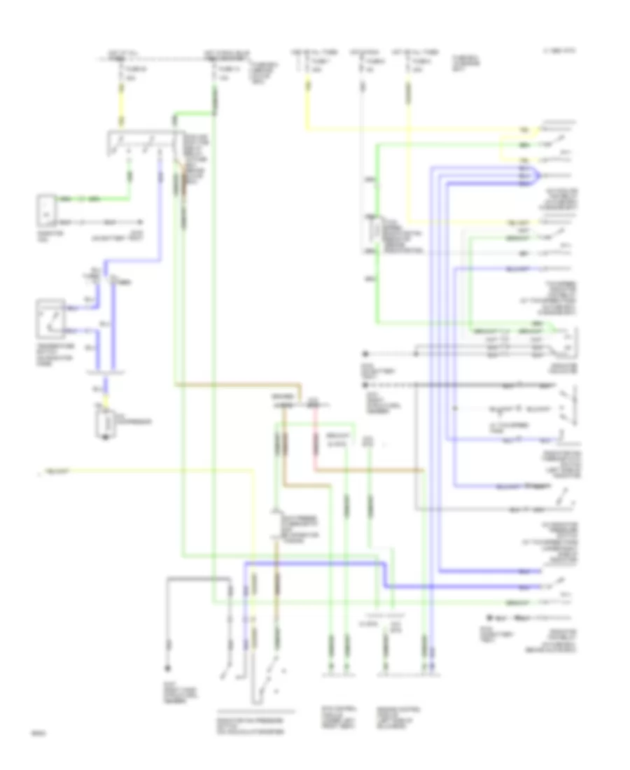
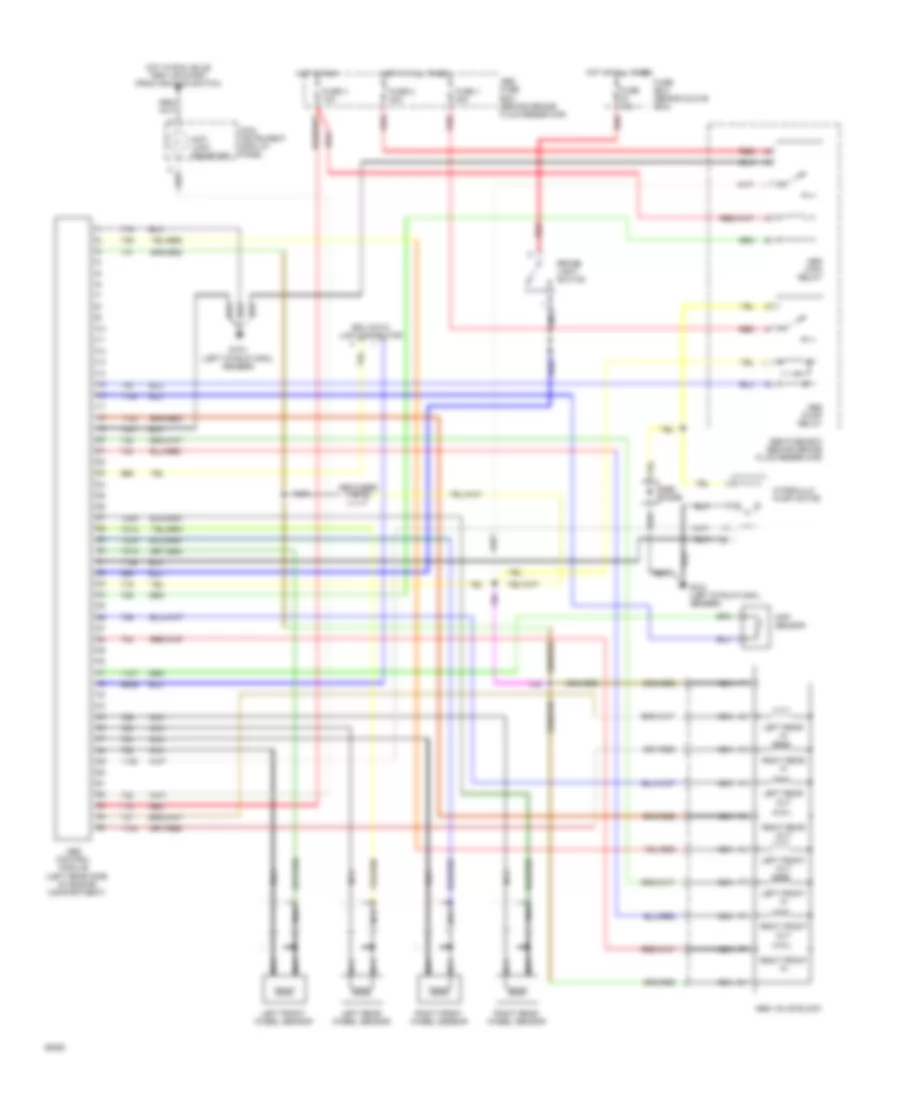
AIR CONDITIONING
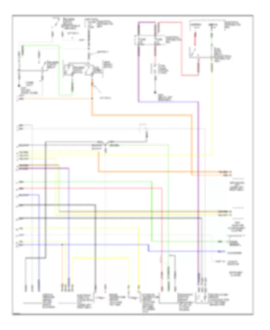
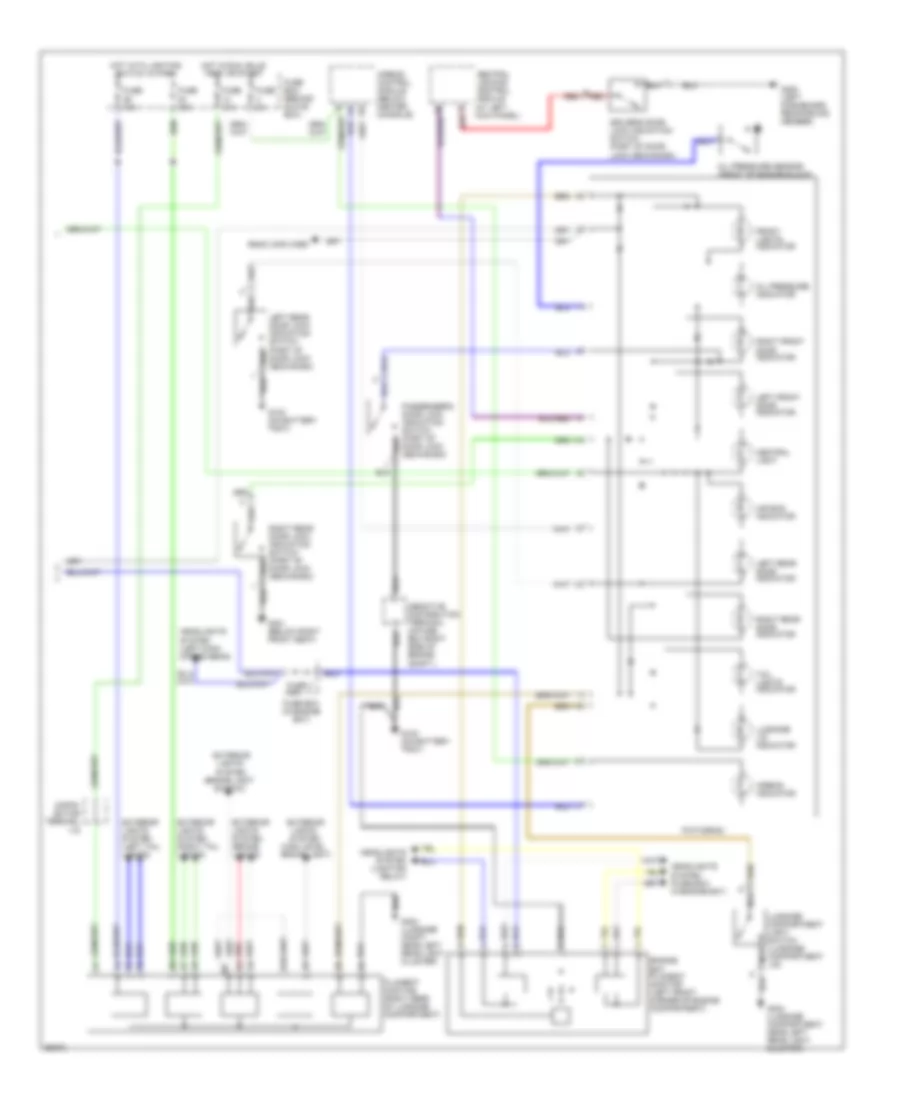
A/C Wiring Diagram (1 of 2) for Saab Aero 1994 9000
 https://portal-diagnostov.com/license.html
Automotive Electricians Portal FZCO
Automotive Electricians Portal FZCO
https://portal-diagnostov.com/license.html
https://portal-diagnostov.com/license.html
Automotive Electricians Portal FZCO
Automotive Electricians Portal FZCO
List of elements for A/C Wiring Diagram (1 of 2) for Saab Aero 1994 9000:
- (left dashboard reinforcing member)
- (on battery tray) g102
- Air distribution damper motor (inside glove box)
- Air mix transmitter (under servo motor unit)
- Automatic climate control unit
- C 1995 vftc
- Diagnostic test socket (below right front seat)
- Edu trip computer
- Fuse 10a
- Fuse 30a
- Fuse 5a
- Fuse box (behind glove box)
- G200
- G300 (left front seat member)
- G304 (under left rear seat)
- Hot at all times
- Hot in run
- Hot in run, bulb test or start
- Interior lights system
- Interior temperature sensor (in panel between steering wheel and console)
- Left door fan motor
- Outside temperature sensor (behind left of front spoiler)
- Rear defogger system
- Recirculation damper motor (right side of engine compartment)
- Red
- Right door fan motor
- Scc trip computer (center of fascia)
- Sun sensor (center of fascia)
- Temperature control damper motor (inside glove box)
- Ventilation fan
- Ventilation fan speed control (in evaporator housing, behind bulkhead)
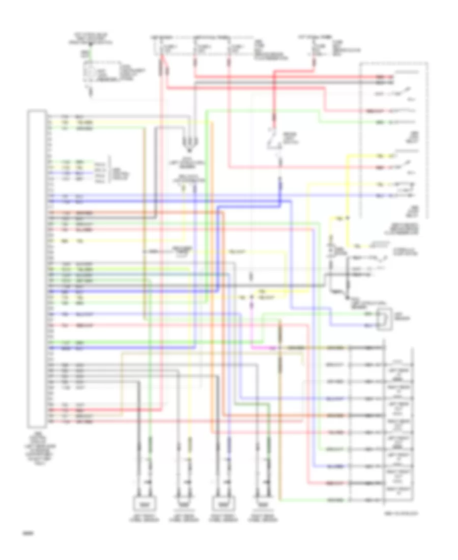
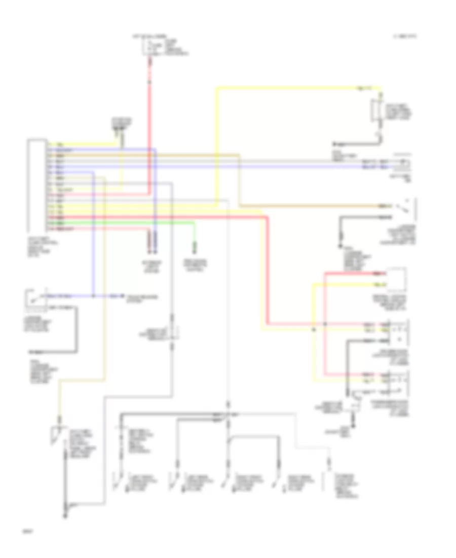
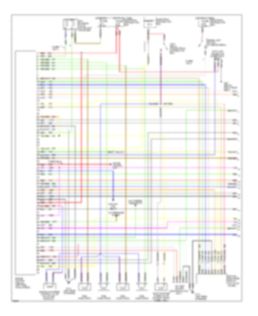
A/C Wiring Diagram (2 of 2) for Saab Aero 1994 9000
List of elements for A/C Wiring Diagram (2 of 2) for Saab Aero 1994 9000:
- (in fuse box, behind glove box)
- (in fuse box, in engine bay)
- (under right side of radiator)
- 10a
- 30a
- A/c compressor
- A/c cooling fan relay (in fuse box in engine bay)
- A/c radiator pressure switch (w/ two-speed fans)
- All others
- Anti-freeze thermostat (on evaporator casing)
- C 1995 vftc
- Cooling fan time delay relay (in fuse box behind glove box)
- Engine control module (left side of bulkhead)
- Ets control module (under left front seat)
- Fuse 13
- Fuse 20
- Fuse 6
- Fuse 7
- Fuse 8
- Fuse box (behind glove box)
- Fuse box (in engine bay)
- G101 (right structural member)
- G102 (on battery tray)
- G107 (right hand structural member)
- Hot at all times
- Hot in run
- Hot in run, bulb test or start
- Nca
- Radiator fan
- Radiator fan motor
- Radiator fan pressure switch (on accumulator/dryer)
- Radiator fan relay
- Radiator fan thermostatic switch (left side of radiator)
- Temperature switch (on radiator hose)
- Turbo a/t
- Two- speed radiator fan resistor (beside radiator fan)
- Two-speed radiator fan relay (w/ two-speed fans)
- W/ ets
- W/ two-speed fans
- W/o ets
ANTI-LOCK BRAKES
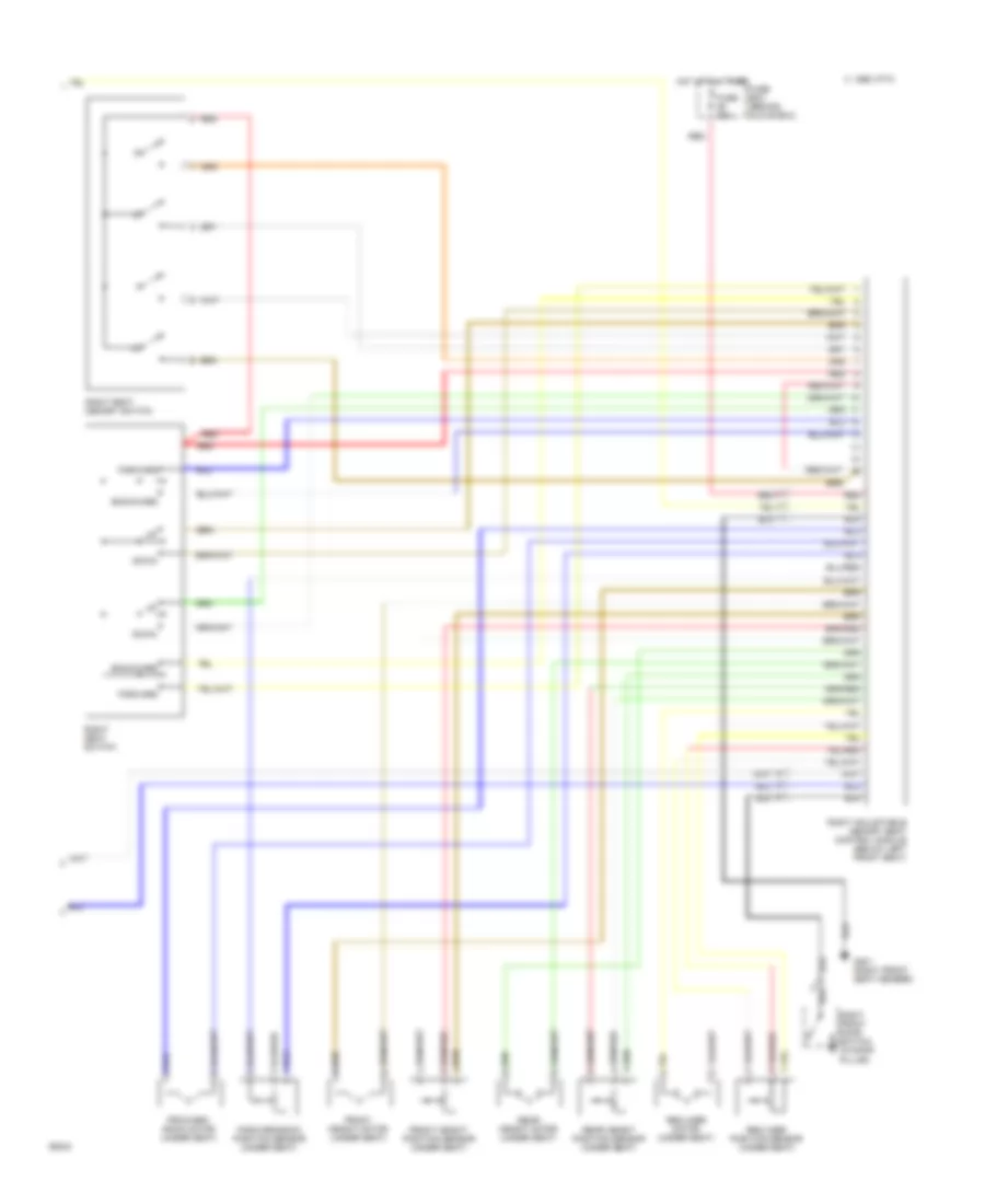
Anti-lock Brake Wiring Diagrams, with Traction Control, Automatic Mark IV (1 of 2) for Saab Aero 1994 9000
List of elements for Anti-lock Brake Wiring Diagrams, with Traction Control, Automatic Mark IV (1 of 2) for Saab Aero 1994 9000:
- (left rear side of engine compartment,
- 721a
- 723a
- 725a
- 727a
- 960b
- Abs control module
- Abs diode
- Abs fuse box (behind brake fluid reservoir)
- Abs main relay
- Abs pump relay
- Abs valve block
- Anti lock indicator
- App sensor
- Asr control module
- Brake light switch
- Edu data link connector
- Fuse 1 30a
- Fuse 15a
- Fuse 2 30a
- Fuse 3 10a
- Fuse box (behind glove box)
- G104 (left structural member)
- Hot at all times
- Hot in run
- Hot in run, bulb test or start (from ignition switch)
- Hydraulic pump motor
- Left front in
- Left front out
- Left front wheel sensor
- Left rear in
- Left rear out
- Left rear wheel sensor
- Main instrument display panel
- Nca
- On battery tray)
- Pin 10
- Pin 21
- Pin 8
- Pin 9
- Red
- Right front in
- Right front out
- Right front wheel sensor
- Right rear in
- Right rear out
- Right rear wheel sensor
Anti-lock Brake Wiring Diagrams, with Traction Control, Automatic Mark IV (2 of 2) for Saab Aero 1994 9000
List of elements for Anti-lock Brake Wiring Diagrams, with Traction Control, Automatic Mark IV (2 of 2) for Saab Aero 1994 9000:
- (rear of engine,
- Abs control module
- Accelerator pedal position sensor
- Asr actuator motor
- Asr control module (under left front seat)
- Below intake manifold)
- Brake light switch
- Cooling fan relay
- Cruise control brake switch
- Cruise control switch
- Distribution terminal +15
- Drive-train data link connector
- Engine control module
- Engine temp. sensor
- Ets bypass valve
- Ets control module (under left front seat)
- Ets dump valve
- Ets main relay
- Ets motor
- Fuse 10a
- Fuse 15a
- Fuse 25a
- Fuse 5a
- Fuse box (behind glove box)
- G114
- Gear select pin 4 switch
- Hot at all times
- Hot in run or start
- Main instrument display panel
- Main instrument display panel pin 4
- Off
- Pin 10
- Pin 11
- Pin 12
- Pin 2
- Pin 27
- Pin 35
- Pin 57
- Pin 58
- Pin 6
- Pin 9
- Pressure sw cooling fan
- Red
- Resume
- Set
- Speed sensor
- Tcs off warning lamp
- Therm0stat anti-freeze
Anti-lock Brake Wiring Diagrams, with Traction Control, Manual Mark II (1 of 2) for Saab Aero 1994 9000
List of elements for Anti-lock Brake Wiring Diagrams, with Traction Control, Manual Mark II (1 of 2) for Saab Aero 1994 9000:
- 720b
- 721a
- 723a
- 725a
- 727a
- 750a
- 960b
- Abs diode
- Abs fuse box (behind brake fluid reservoir)
- Abs main relay
- Abs pump relay
- Abs valve block
- Abs/tcs warning lamp
- Brake fluid level sensor
- Brake fluid level warning lamp
- Brake light switch
- Edu data link connector
- Ets control module
- Fuse 1 30a
- Fuse 15a
- Fuse 2 30a
- Fuse 3 10a
- Fuse box (behind glove box)
- G104 (left structural member)
- Hot at all times
- Hot in run
- Hot in run, bulb test or start (from ignition switch)
- Hydraulic pump motor
- Left front in
- Left front out
- Left front wheel sensor
- Left rear wheel sensor
- Main instrument display panel
- Main valve
- Nca
- Pin 29
- Pin 32
- Rear in
- Rear out
- Red
- Right front in
- Right front out
- Right front wheel sensor
- Right rear wheel sensor
- Tc-abs control module (left rear side of engine compartment, on battery tray)
- Tc-abs pressure switch
- Tc-abs valve block
- Tcs indic. lamp
- Tcs warning lamp
Anti-lock Brake Wiring Diagrams, with Traction Control, Manual Mark II (2 of 2) for Saab Aero 1994 9000
List of elements for Anti-lock Brake Wiring Diagrams, with Traction Control, Manual Mark II (2 of 2) for Saab Aero 1994 9000:
- Accelerator pedal position sensor
- Anti-freeze thermostat
- Brake light switch
- C 1995 vftc
- Cruise control brake switch
- Cruise control switch
- Distribution terminal +15
- Drive-train data link connector
- Engine control module
- Engine temperature sensor
- Ets bypass valve
- Ets control module (under right front seat)
- Ets dump valve
- Ets main relay
- Ets motor
- Fuse 10a
- Fuse 15a
- Fuse 25a
- Fuse 5a
- Fuse box (behind glove box)
- G114 (rear of engine, below intake manifold)
- Hot at all times
- Hot in run or start
- Main instrument display panel
- Off
- Pin 24
- Pin 35
- Pin 4
- Pin 57
- Pin 58
- Pin 6
- Pressure switch cooling fan
- Red
- Relay cooling fan
- Resume
- Set
- Speed sensor pin 2
- Tc-abs control module
- Tcs off warning lamp
Anti-lock Brake Wiring Diagrams, without Traction Control, Mark IV for Saab Aero 1994 9000
List of elements for Anti-lock Brake Wiring Diagrams, without Traction Control, Mark IV for Saab Aero 1994 9000:
- (left rear side of engine compartment)
- 721a
- 723a
- 725a
- 727a
- 960b
- Abs control module
- Abs diode
- Abs fuse box (behind brake fluid reservoir)
- Abs main relay
- Abs pump relay
- Abs valve block
- Anti lock indicator
- App sensor
- Brake light switch
- Edu data link connector
- Fuse 1 30a
- Fuse 15a
- Fuse 2 30a
- Fuse 3 10a
- Fuse box (behind glove box)
- G104 (left structural member)
- Hot at all times
- Hot in run
- Hot in run, bulb test or start (from ignition switch)
- Hydraulic pump motor
- Left front in
- Left front out
- Left front wheel sensor
- Left rear in
- Left rear out
- Left rear wheel sensor
- Main instrument display panel
- Nca
- Red
- Right front in
- Right front out
- Right front wheel sensor
- Right rear in
- Right rear out
- Right rear wheel sensor
ANTI-THEFT
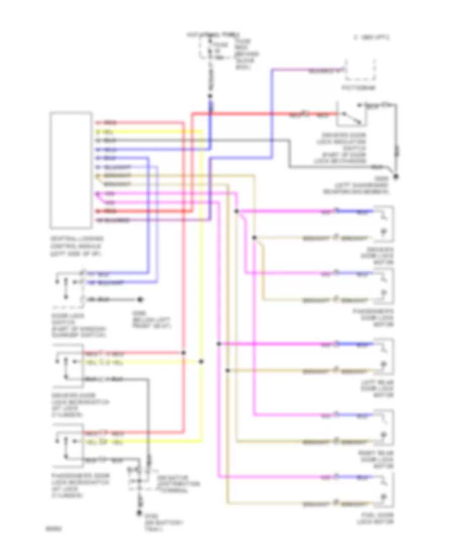
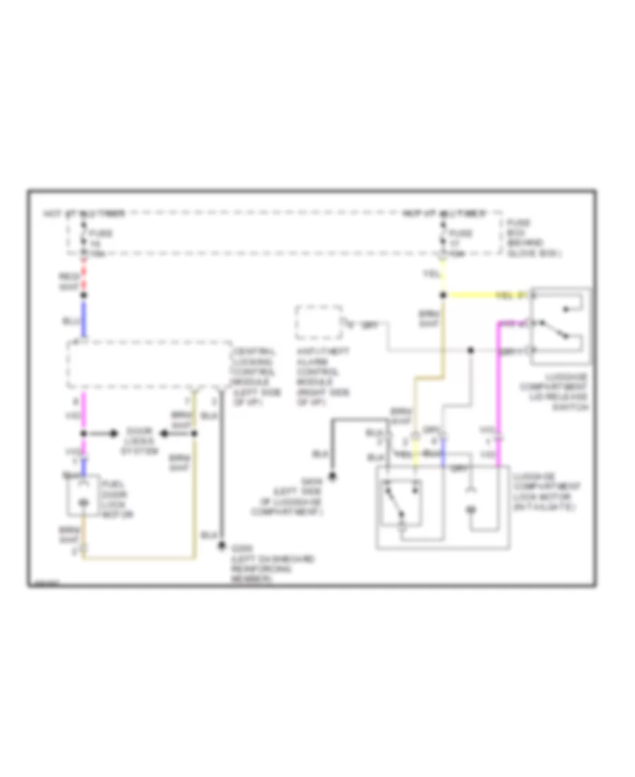
Anti-theft Wiring Diagram for Saab Aero 1994 9000
List of elements for Anti-theft Wiring Diagram for Saab Aero 1994 9000:
- (at lock cylinder)
- (on battery
- Anti-theft alarm control module (right side of i/p)
- Anti-theft alarm hood switch (on front panel, above left front headlamp)
- Anti-theft alarm siren (in left hand front wing)
- Anti-theft led
- C 1995 vftc
- Central locking control module (behind left side of i/p)
- Distribution
- Driver's door
- Exterior lights system
- Fuse 15a
- Fuse box (behind glove box)
- G102
- G102 (on battery tray)
- G404 (luggage compartment near left rear light cluster)
- Hot at all times
- Interior lighting time delay relay (behind glove box)
- Left front door switch (in door pillar)
- Left rear door switch (in door pillar)
- Lock microswitch
- Luggage compartment light switch (in luggage compartment lid)
- Luggage compartment lock motor (in tailgate)
- Passenger's door lock microswitch
- Provisions for remote control
- Red
- Right front door switch (in door pillar)
- Right rear door switch (in door pillar)
- Seatbelt/ key ignition warning relay (behind glove box)
- Starting/ charging system
- Terminal
- Tray)
- Trunk release system
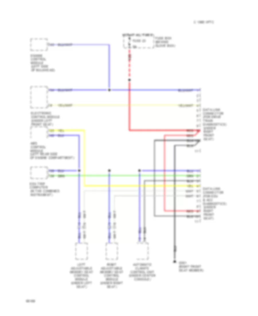
COMPUTER DATA LINES
Computer Data Lines for Saab Aero 1994 9000
List of elements for Computer Data Lines for Saab Aero 1994 9000:
- 1995 vftc c
- Abs control module (left rear side of engine compartment)
- Automatic climate control unit (under center console)
- Data link connector (for drive train diagnostics) (under right front seat)
- Data link connector (for edu & acc diagnostics) (under right front seat)
- Edu trip computer (in the combined instrument)
- Electronic control module (under left front seat)
- Engine control module (left side of bulkhead)
- Fuse 23
- Fuse box (behind glove box)
- G301 (right front seat member)
- Hot at all times
- Left adjustable memory seat control module (under left seat)
- Red
- Right adjustable memory seat control module (under right seat)
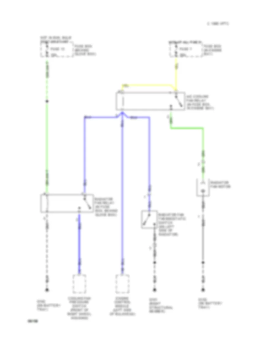
COOLING FAN
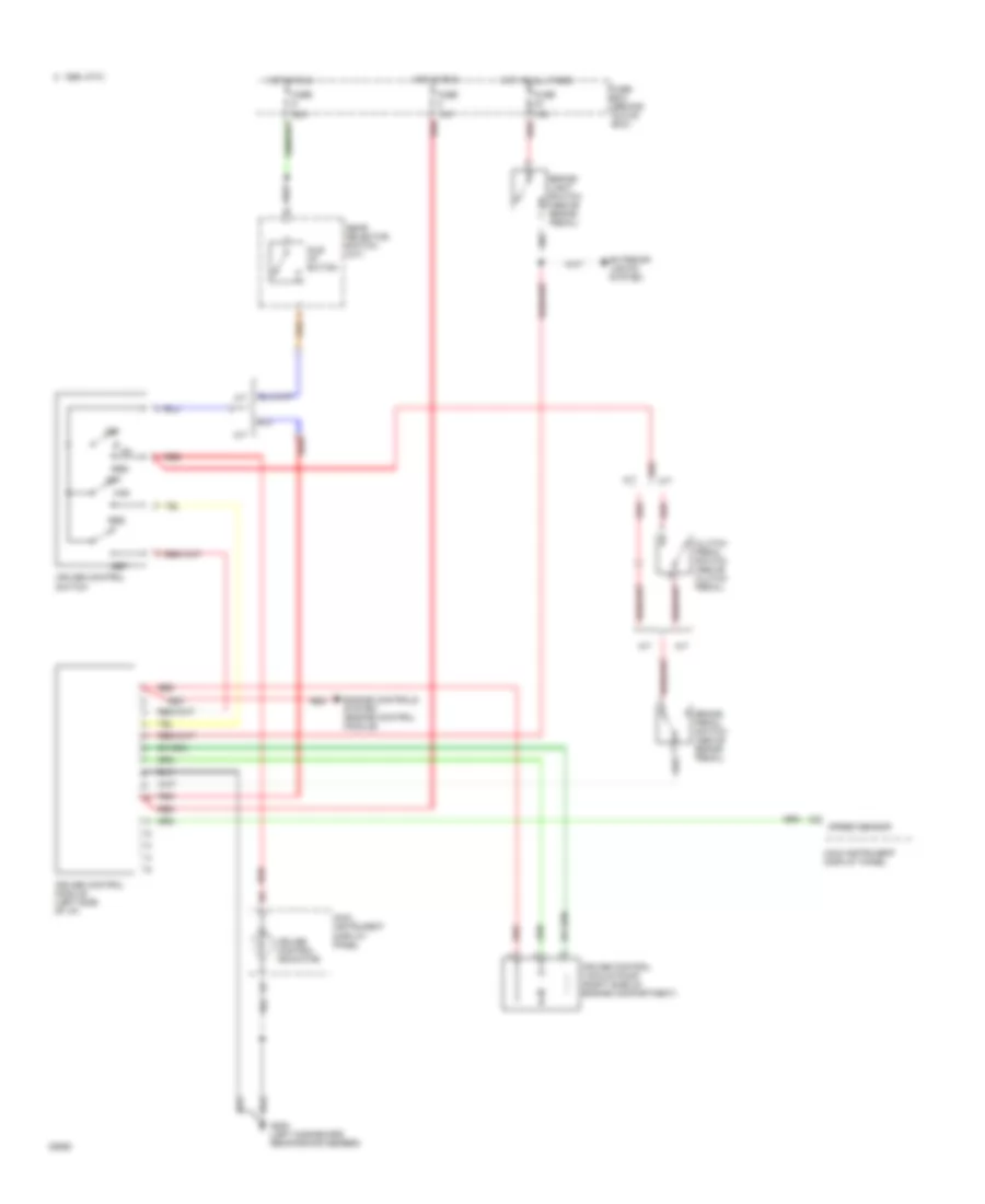
Cooling Fan Wiring Diagram, Single Speed Radiator Fan for Saab Aero 1994 9000
List of elements for Cooling Fan Wiring Diagram, Single Speed Radiator Fan for Saab Aero 1994 9000:
- 10a
- 1995 vftc c
- 30a
- A/c cooling fan relay (in fuse box, in engine bay)
- Cooling fan pressure switch (front of right wheel housing)
- Engine control module (left side of bulkhead)
- Fuse 13
- Fuse 7
- Fuse box (behind glove box)
- Fuse box (in engine bay)
- G101 (right structural member)
- G102 (on battery tray)
- Hot at all times
- Hot in run, bulb test or start
- Radiator fan motor
- Radiator fan relay (in fuse box, behind glove box)
- Radiator fan thermostatic switch (on left side of radiator)
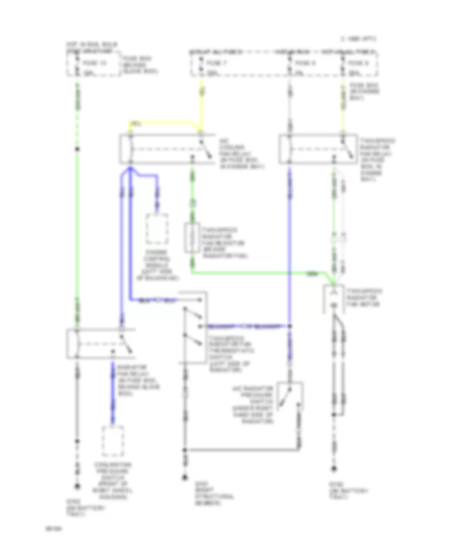
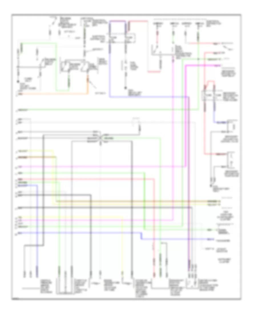
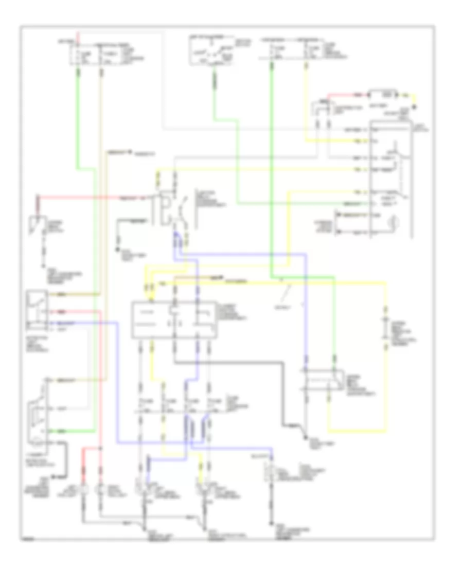
Cooling Fan Wiring Diagram, Two Speed Radiator Fan for Saab Aero 1994 9000
List of elements for Cooling Fan Wiring Diagram, Two Speed Radiator Fan for Saab Aero 1994 9000:
- 10a
- 1995 vftc c
- 30a
- A/c cooling fan relay (in fuse box, in engine bay)
- A/c radiator pressure switch (under right hand side of radiator)
- Cooling fan pressure switch (front of right wheel housing)
- Engine control module (left side of bulkhead)
- Fuse 13
- Fuse 6
- Fuse 7
- Fuse 8
- Fuse box (behind glove box)
- Fuse box (in engine bay)
- G101 (right structural member)
- G102 (on battery tray)
- Hot at all times
- Hot in run
- Hot in run, bulb test or start
- Nca
- Radiator fan relay (in fuse box, behind glove box)
- Two-speed radiator fan motor
- Two-speed radiator fan relay (in fuse box, in engine bay)
- Two-speed radiator fan resistor (beside radiator fan)
- Two-speed radiator fan thermostatic switch (left side of radiator)
CRUISE CONTROL
Cruise Control Wiring Diagram for Saab Aero 1994 9000
List of elements for Cruise Control Wiring Diagram for Saab Aero 1994 9000:
- 10a
- 15a
- 25a
- A/t
- Brake light switch (above brake pedal)
- Brake pedal switch (above brake pedal)
- C 1995 vftc
- Clutch pedal switch (above clutch pedal)
- Cruise control indicator
- Cruise control module (left side of i/p)
- Cruise control switch
- Cruise control vacuum pump (right side of engine compartment)
- Engine controls system (engine control module)
- Exterior lights system
- Fuse
- Fuse box (behind glove box)
- G200 (left dashboard reinforcing member)
- Gear selector switch (a/t)
- Hot at all times
- Hot in run
- Idle up switch
- M/t
- Main instrument display panel
- Off
- Red
- Res
- Set
- Speed sensor
DEFOGGERS
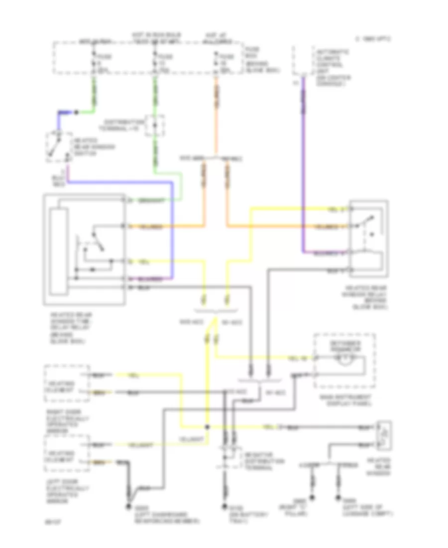
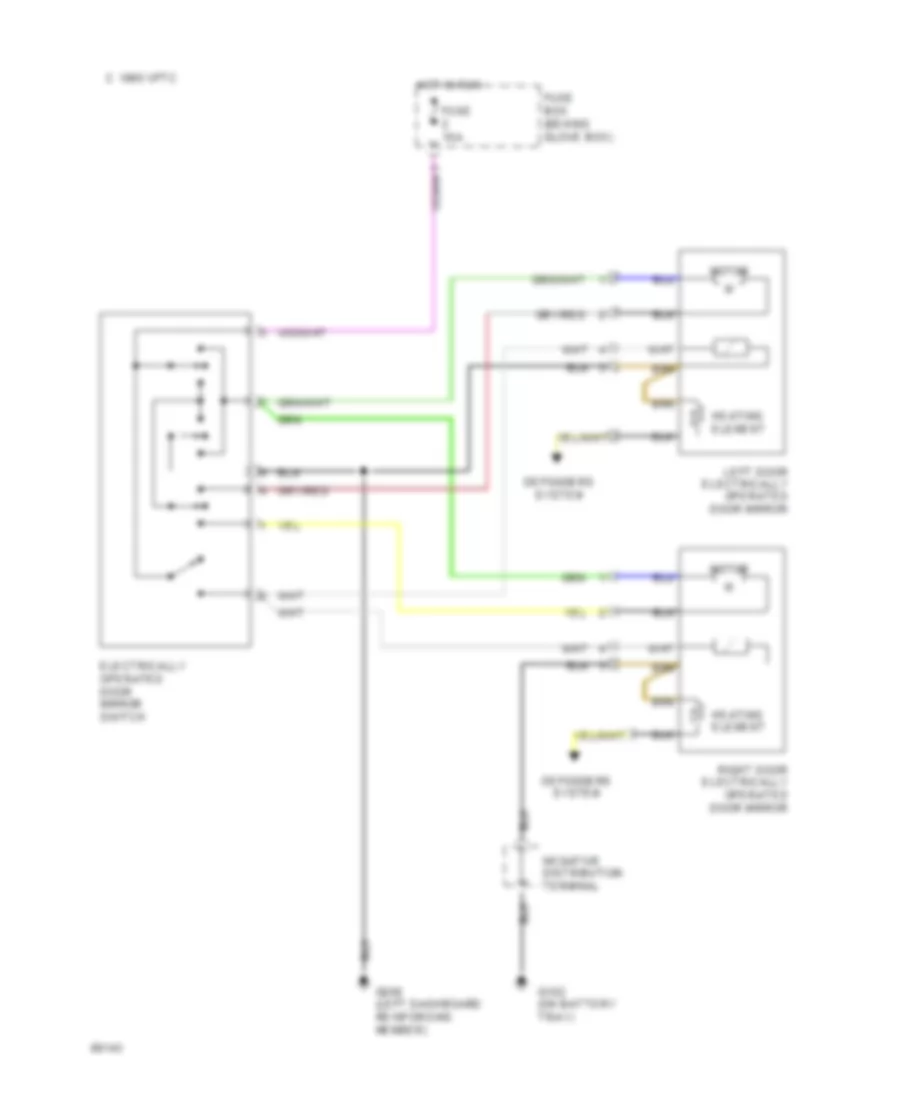
Defogger Wiring Diagram for Saab Aero 1994 9000
List of elements for Defogger Wiring Diagram for Saab Aero 1994 9000:
- (behind glove box)
- 1995 vftc c
- 4 door
- 5 door
- Automatic climate control unit (on center console)
- Defogger indicator
- Distribution
- Fuse 10a
- Fuse 25a
- Fuse 30a
- Fuse box
- G102 (on battery tray)
- G200 (left dashboard reinforcing member)
- G404 (left side of luggage compt)
- G905 (right "c" pillar)
- Heated rear window
- Heated rear window relay (behind glove box)
- Heated rear window switch
- Heated rear window time- delay relay
- Heating element
- Hot at all times
- Hot in run
- Hot in run bulb test or start
- Left door electrically operated mirror
- Main instrument display panel
- Right door electrically operated mirror
- Terminal +15
- W/ acc
- W/o acc
ENGINE PERFORMANCE
2.3L
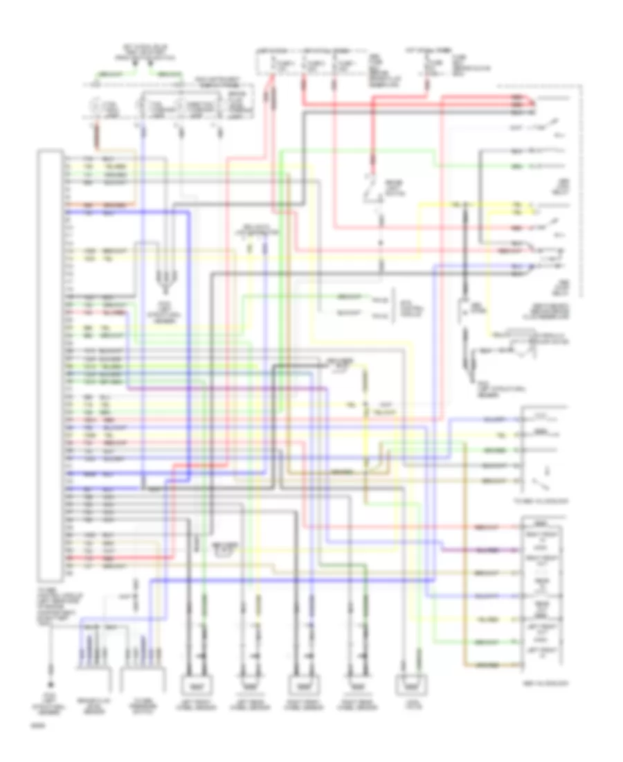
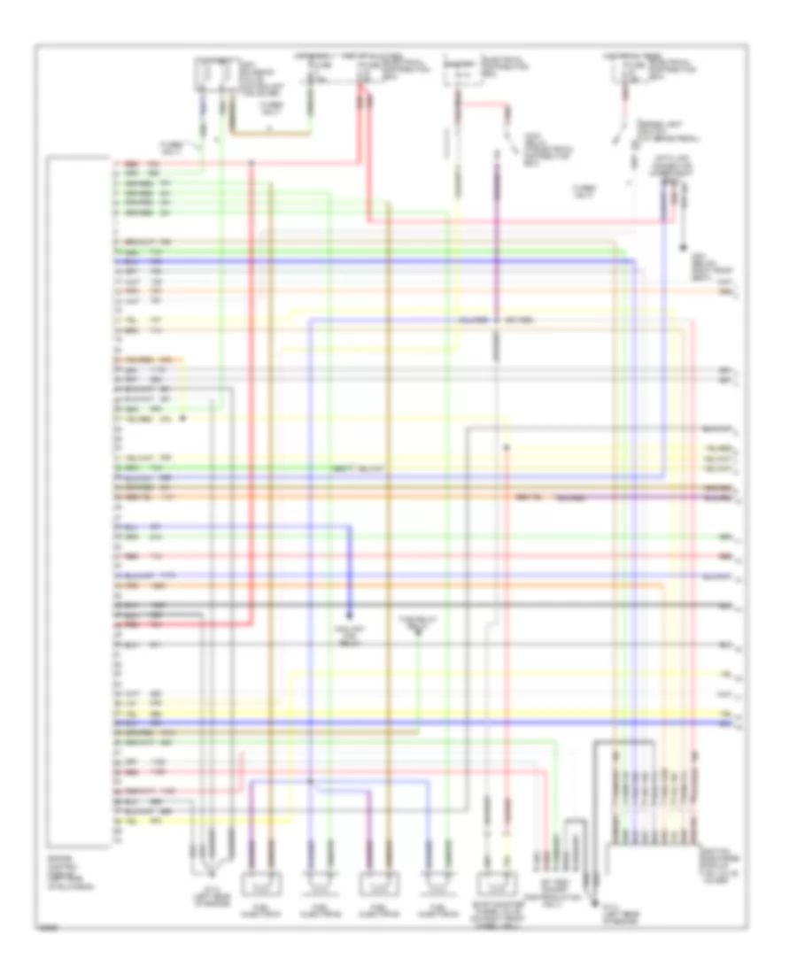
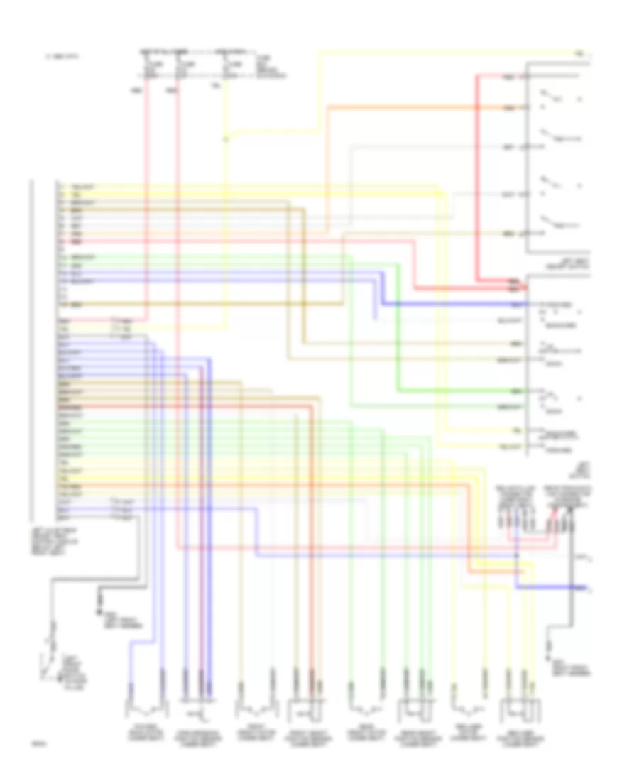
2.3L, Engine Performance Wiring Diagrams, with Electronic Throttle System (1 of 2) for Saab Aero 1994 9000
List of elements for 2.3L, Engine Performance Wiring Diagrams, with Electronic Throttle System (1 of 2) for Saab Aero 1994 9000:
- (for production only)
- (on valve cover)
- (turbo only)
- Apc solenoid valve (on coolant fan cover)
- Battery
- Brake light switch (at brake pedal)
- Coolant fan relay
- Data link connector (under right seat)
- Electrical distribution box
- Engine control module (left side of bulkhead)
- Evap canister purge valve (on right front wheel well)
- Fuel injector #1
- Fuel injector #2
- Fuel injector #3
- Fuel injector #4
- Fuse 10a
- Fuse 15a
- Fuse 5a
- G114 (left rear of engine)
- G301 (below right front seat)
- Hot at all times
- Hot in run
- Ignition discharge module
- Main relay (in electrical distribution box)
- Red
- Sfi test socket
- Time delay relay
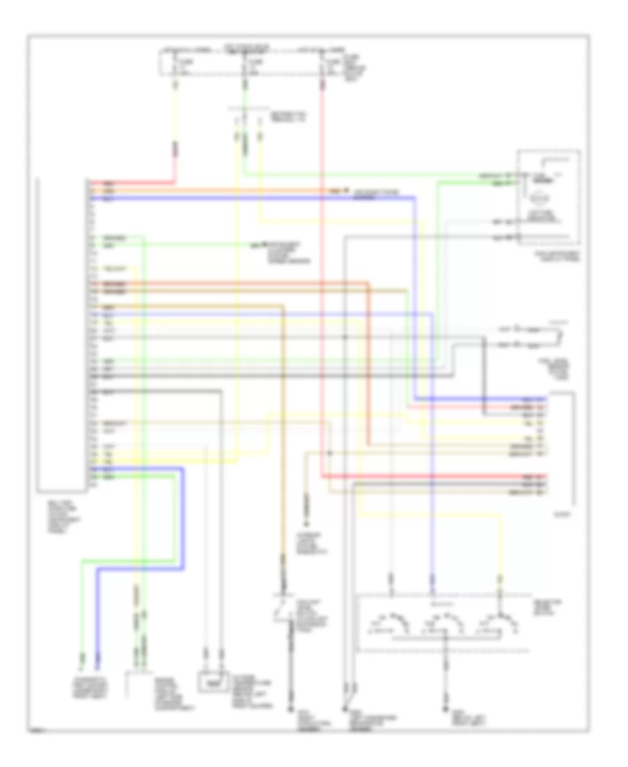
2.3L, Engine Performance Wiring Diagrams, with Electronic Throttle System (2 of 2) for Saab Aero 1994 9000
List of elements for 2.3L, Engine Performance Wiring Diagrams, with Electronic Throttle System (2 of 2) for Saab Aero 1994 9000:
- (a/t only)
- (behind belt pulley on oil pump housing)
- (in exhaust pipe at the turbo branch pipe)
- (in instrument cluster)
- (m/t only)
- (turbo only)
- (under left front seat)
- Asr control
- Battery
- Cluster
- Computer
- Crankshaft position sensor
- Electrical distribution box
- Electronic throttle system (ets) unit (under left front seat)
- Engine temperature sensor (on intake air tube)
- Fuel pump (in fuel tank)
- Fuel pump relay (in electrical distribution box)
- Fuse 10a
- Fuse 20a
- Fuse 25a
- G102 (on left shock tower)
- G304 (below left rear seat)
- Gear select switch
- Heated oxygen sensor
- Hot in run
- Idle speed switch
- Ignition
- Instrument
- Intake air temperature sensor (on intake manifold, between cylinders 2 & 3)
- Manifold pressure sensor (on left side of bulkhead)
- Nca
- Red
- Reverse lights relay
- Reverse lights switch
- Reverse lights switch (left siide of gear box)
- Speed sensor
- Tachometer
- Trip
- Unit
- Up shift indicator
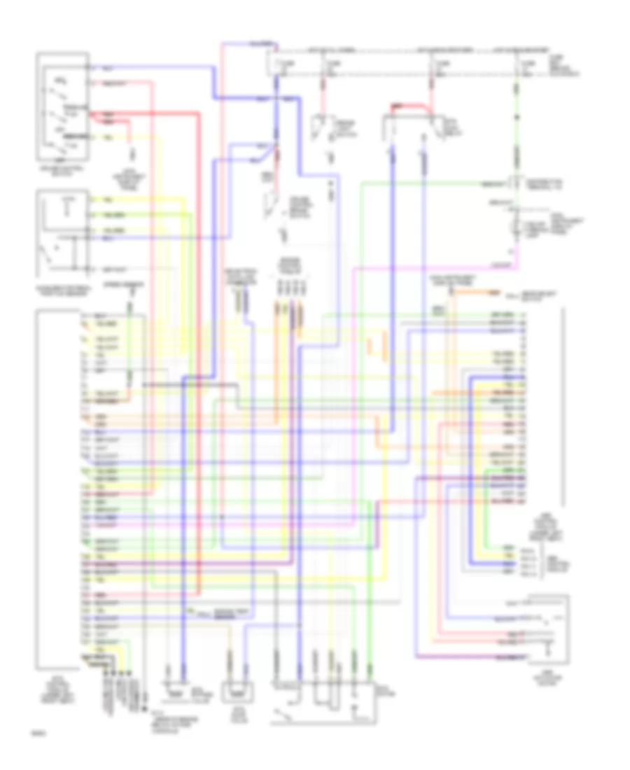
2.3L, Engine Performance Wiring Diagrams, without Electronic Throttle System (1 of 2) for Saab Aero 1994 9000
List of elements for 2.3L, Engine Performance Wiring Diagrams, without Electronic Throttle System (1 of 2) for Saab Aero 1994 9000:
- (for production only)
- (left rear of engine)
- (on valve cover)
- (turbo only)
- A/c pressure switch
- Anti freeze thermostat
- Apc solenoid valve (on coolant fan cover)
- Battery
- Brake light switch (at brake pedal)
- Coolant fan relay
- Cruise control unit
- Data link connector (under right seat)
- Electrical distribution box
- Engine control module (left side of bulkhead)
- Engine idle speed control valve (on intake manifold)
- Evap canister purge valve (on right front wheel well)
- Fuel injector #1
- Fuel injector #2
- Fuel injector #3
- Fuel injector #4
- Fuse 10a
- Fuse 15a
- Fuse 5a
- G114
- G114 (left rear of engine)
- G301 (below right front seat)
- Hot at all times
- Hot in run
- Ignition discharge module
- Main relay (in electrical distribution box)
- Red
- Sfi test socket
2.3L, Engine Performance Wiring Diagrams, without Electronic Throttle System (2 of 2) for Saab Aero 1994 9000
List of elements for 2.3L, Engine Performance Wiring Diagrams, without Electronic Throttle System (2 of 2) for Saab Aero 1994 9000:
- (a/t only)
- (behind belt pulley on oil pump housing)
- (in exhaust pipe at the turbo branch pipe)
- (in instrument cluster)
- (m/t only)
- (turbo only)
- Battery
- Cluster
- Computer
- Crankshaft position sensor
- Distribution box
- Electrical
- Electrical distribution box
- Engine temperature sensor (on intake air tube)
- Fuel pump (in fuel tank)
- Fuel pump relay (in electrical distribution box)
- Fuse
- Fuse 10a
- Fuse 20a
- Fuse 25a
- G102 (near battery tray)
- G102 (on left shock tower)
- G304 (below left rear seat)
- Gear select switch
- Heated oxygen sensor
- Hot in run
- Idle speed switch
- Ignition
- Instrument
- Intake air temperature sensor (on intake manifold, between cylinders 2 and 3)
- Manifold pressure sensor (on left side of bulkhead)
- Nca
- Red
- Reverse lights relay
- Reverse lights switch
- Reverse lights switch (left siide of gear box)
- Secondary air injection control valve
- Secondary air injection pump motor
- Secondary air injection pump relay
- Secondary air injection relay and fuse holder
- Speed sensor
- Tachometer
- Throttle position sensor (on throttle body)
- Trip
- Up shift indicator
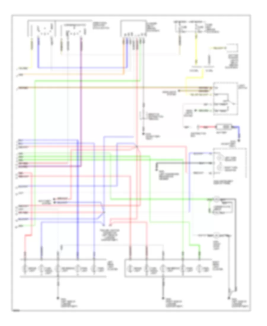
EXTERIOR LIGHTS
Exterior Light Wiring Diagram, 4 Door (1 of 2) for Saab Aero 1994 9000
List of elements for Exterior Light Wiring Diagram, 4 Door (1 of 2) for Saab Aero 1994 9000:
- A/t
- B10
- Brake light switch (at brake pedal)
- Distribution terminal +15
- Filament monitor (right rear of luggage compartment)
- Fuse 10a
- Fuse 15a
- Fuse 25a
- Fuse box (behind glove box)
- G100 (behind left headlamp)
- G100 (behind left headlight)
- G101 (right structural member)
- G102 (on battery tray)
- G200 (left dashboard reinforcing member)
- G404 (left side of luggage compartment)
- Gear selector switch (under center console)
- Hazard flasher switch
- Hot at all times
- Hot in run
- Hot in run, bulb test or start
- Illum
- Instrument cluster system
- Left front cornering light
- Left front park light
- Left front side reversing light
- Left side marker light
- Left side turn signal light
- Left turn signal light
- M/t
- Red
- Reversing light relay (behind glove box)
- Reversing light switch (left side of gear box)
- Rheostat
- Right front cornering light
- Right front park light
- Right front side reversing light
- Right side marker light
- Right turn signal light
- Trailer lighting connector (left rear of luggage compartment)
- With side marker light only
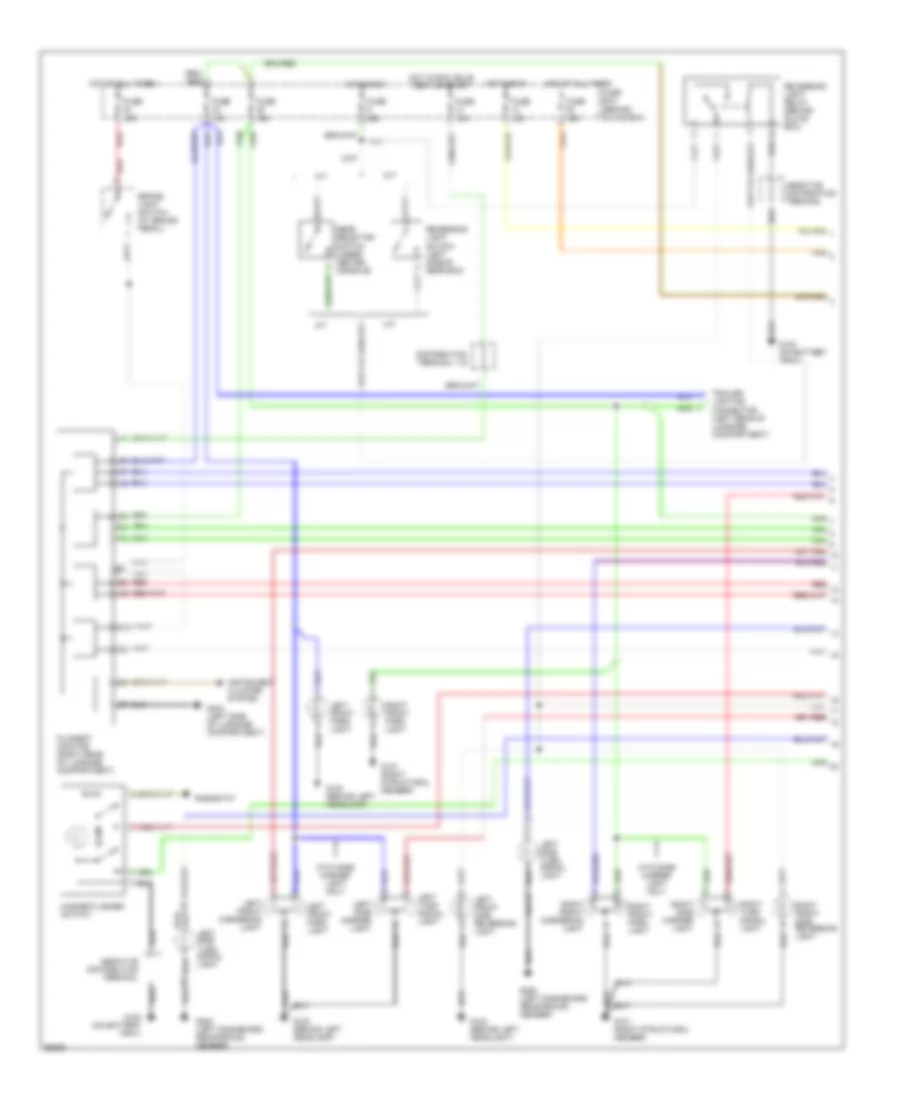
Exterior Light Wiring Diagram, 4 Door (2 of 2) for Saab Aero 1994 9000
List of elements for Exterior Light Wiring Diagram, 4 Door (2 of 2) for Saab Aero 1994 9000:
- 49l
- 49r
- Anti-theft system
- Battery
- Brake light
- Cornering switch
- Daytime running lights relay (behind glove box)
- Directional indicator stalk switch
- Distribution box
- Flasher relay (behind glove box)
- Fuse 10a
- Fuse 15a
- Fuse box (behind glove box)
- G102 (on battery tray)
- G200 (left dashboard reinforcing member)
- G404 (left side of luggage compartment)
- G405 (right side of luggage compartment)
- Head
- Head- lights system
- Headlights system
- High mount stop light
- Hot in run
- Left
- Left rear light cluster
- Left turn indicator
- License plate lights
- Light switch
- Main instrument display panel
- Off
- Park
- Park light
- Red
- Reversing light
- Right
- Right rear light cluster
- Right turn indicator
- Trailer lighting connector (left rear of luggage compartment)
- Turn signal light
- W/ drl
- W/o drl
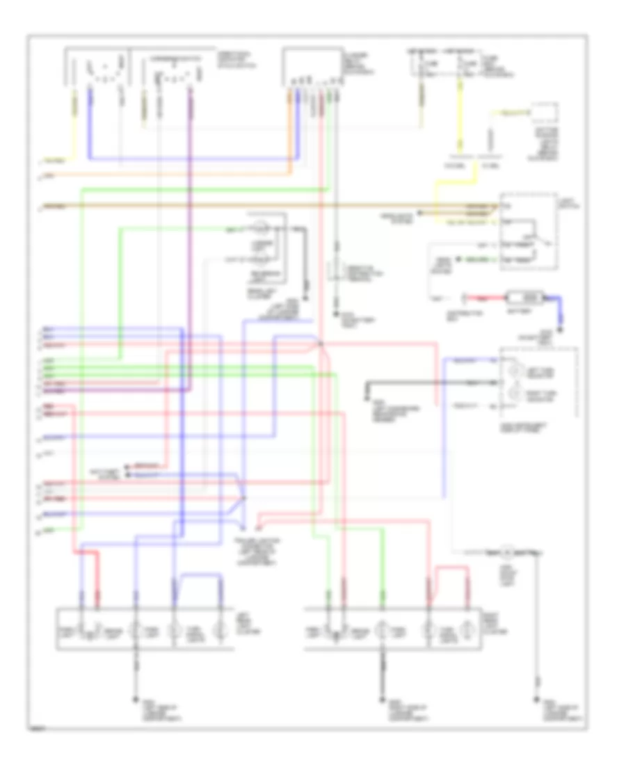
Exterior Light Wiring Diagram, 5 Door (1 of 2) for Saab Aero 1994 9000
List of elements for Exterior Light Wiring Diagram, 5 Door (1 of 2) for Saab Aero 1994 9000:
- A/t
- B10
- Brake light switch (at brake pedal)
- Distribution terminal +15
- Filament monitor (right rear of luggage compartment)
- Fuse 10a
- Fuse 15a
- Fuse 25a
- Fuse box (behind glove box)
- G100 (behind left headlamp)
- G100 (behind left headlight)
- G101 (right structural member)
- G102 (on battery tray)
- G200 (left dashboard reinforcing member)
- G404 (left side of luggage compartment)
- Gear selector switch (under center console)
- Hazard flasher switch
- Hot at all times
- Hot in run
- Hot in run, bulb test or start
- Illum
- Instrument cluster system
- Left front cornering light
- Left front park light
- Left front side reversing light
- Left side marker light
- Left side turn signal light
- Left turn signal light
- M/t
- Red
- Reversing light relay (behind glove box)
- Reversing light switch (left side of gear box)
- Rheostat
- Right front cornering light
- Right front park light
- Right front side reversing light
- Right side marker light
- Right turn signal light
- Trailer lighting connector (left rear of luggage compartment)
- With side marker light only
Exterior Light Wiring Diagram, 5 Door (2 of 2) for Saab Aero 1994 9000
List of elements for Exterior Light Wiring Diagram, 5 Door (2 of 2) for Saab Aero 1994 9000:
- 49l
- 49r
- Anti-theft system
- Battery
- Brake light
- Cornering switch
- Daytime running lights relay (behind glove box)
- Directional indicator stalk switch
- Distribution box
- Flasher relay (behind glove box)
- Fuse 10a
- Fuse 15a
- Fuse box (behind glove box)
- G102 (on battery tray)
- G200 (left dashboard reinforcing member)
- G404 (left side of luggage compartment)
- G405 (right side of luggage compartment)
- Head
- Head- lights system
- Headlights system
- High mount stop light
- Hot in run
- Left
- Left rear light cluster
- Left turn indicator
- License light
- Light switch
- Main instrument display panel
- Off
- Park
- Park light
- Rear light cluster
- Red
- Reversing light
- Right
- Right rear light cluster
- Right turn indicator
- Trailer lighting connector (left rear of luggage compartment)
- Turn signal lights
- W/ drl
- W/o drl
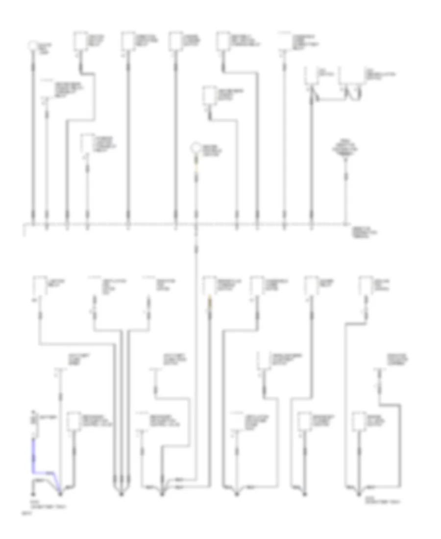
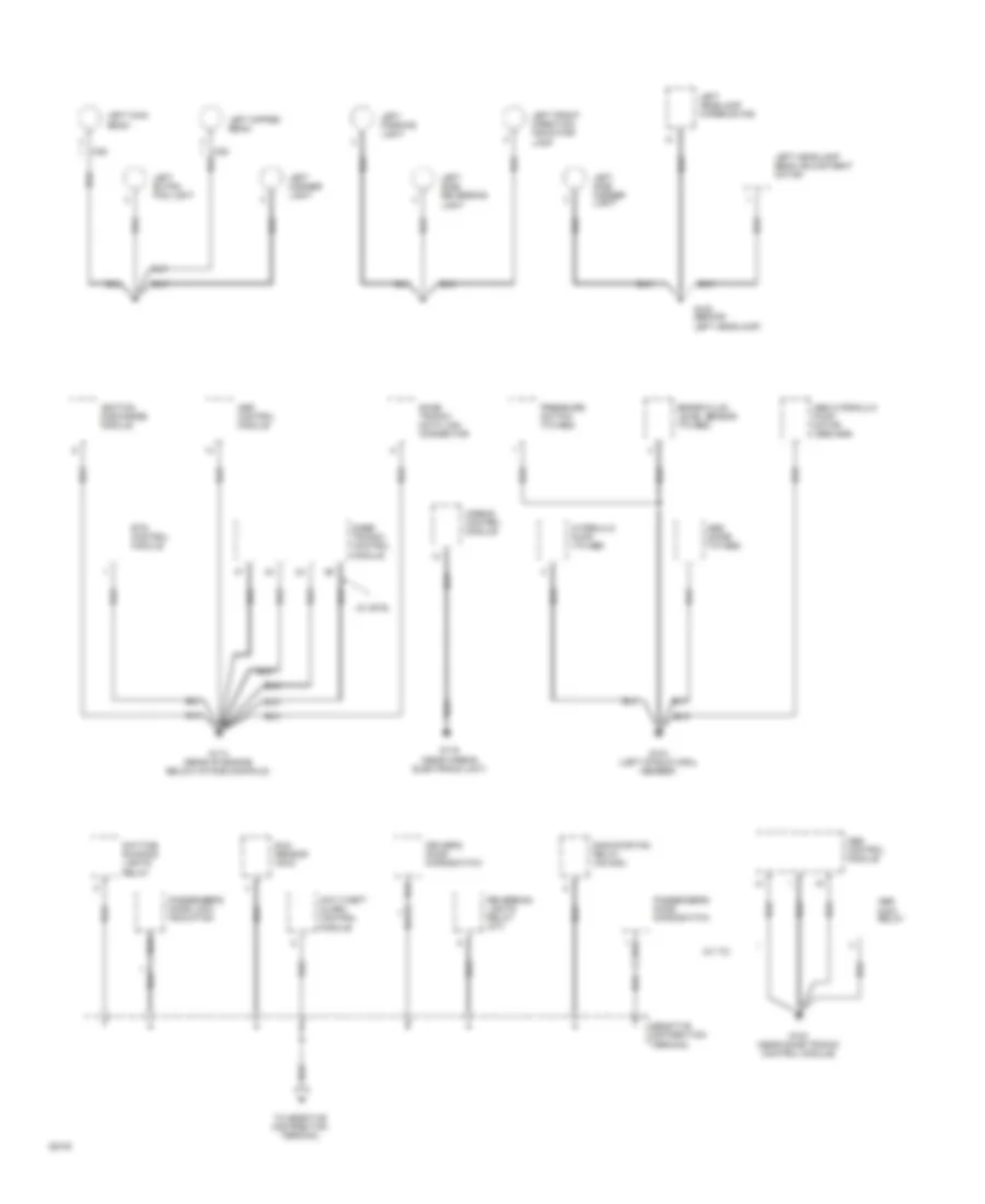
GROUND DISTRIBUTION
Ground Distribution Wiring Diagram (1 of 4) for Saab Aero 1994 9000
List of elements for Ground Distribution Wiring Diagram (1 of 4) for Saab Aero 1994 9000:
- (on battery tray)
- A/c recirculation switch
- A/c switch
- Anti-theft alarm hood switch
- Anti-theft alarm siren
- Battery
- Brake fluid warning switch
- Cooling fan (ac/acc)
- Dimmer relay
- Direction indicators relay
- Engine bay filament monitor
- Engine oil level switch
- G102
- Glove box lamp
- Hazard flasher switch
- Headlamp beam ajustment switch
- Heated rear window relay/ time-delay relay
- Heated rear window switch
- Heater controls lighting
- Ignition switch relay
- Interior lighting time-delay relay
- Lighting relay
- Radiator fan motor
- Radiator fan motor (2-speed)
- Seatbelt/ key ignition warning relay
- Secondary air injection control valve
- Ventilation fan motor (ac)
- Ventilation fan power stage (acc)
- Windshield wiper intermittent relay
- Windshield wiper motor
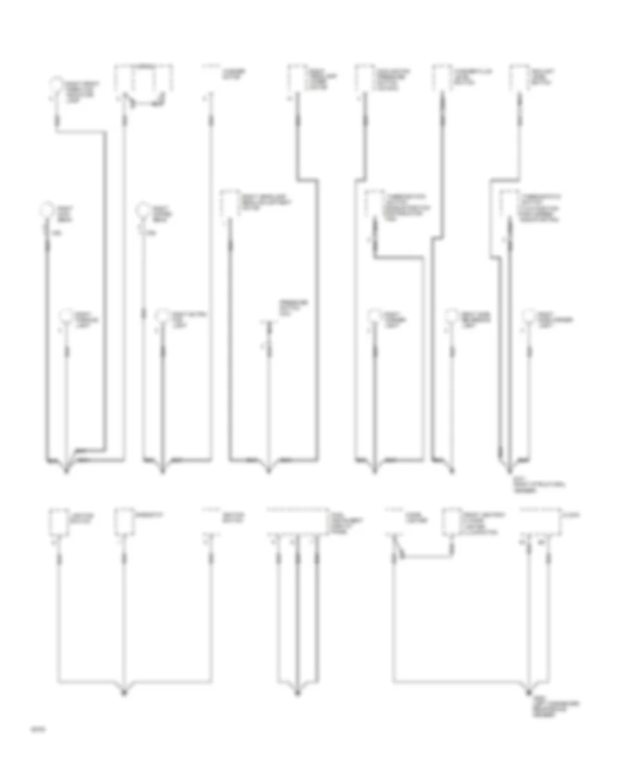
Ground Distribution Wiring Diagram (2 of 4) for Saab Aero 1994 9000
List of elements for Ground Distribution Wiring Diagram (2 of 4) for Saab Aero 1994 9000:
- (cs)
- (w/ ets)
- (w/ tc)
- Abs control module
- Abs diode (tc-abs)
- Abs hydraulic pump motor (abs-asr)
- Abs main relay
- Airbag control module
- Anti-theft alarm control
- Asr control module
- Brake fluid level sensor (tc-abs)
- Daytime running lights relay
- Driver's door microswitch
- Ets control module
- G100 (behind left headlamp)
- G104 (left structural member)
- G104 (near saab trionic control module)
- G114 (rear of engine below intake manifold)
- G116 (near airbag electronic unit)
- Hydraulic pump (tc-abs)
- Ignition discharge module
- Left corner light
- Left dipped beam
- Left extra fog light
- Left front direction indicator lamp
- Left headlamp beam adjustment motor
- Left headlamp wiper motor
- Left main beam
- Left parking light
- Left side marker light
- Left side reversing
- Light
- Module
- Passenger's door lock indication
- Passenger's door microswitch
- Pressure switch (tc-abs)
- Radiator fan relay (ac/acc)
- Reversing lights relay (a/t)
- Saab trionic data link connector
- Sabb trionic control module
- Sun sensor (acc)
- Terminal
Ground Distribution Wiring Diagram (3 of 4) for Saab Aero 1994 9000
List of elements for Ground Distribution Wiring Diagram (3 of 4) for Saab Aero 1994 9000:
- (cs)
- (left dashboard reinforcing member)
- (two position for 2-speed radiator fan)
- Cigar lighter
- Clock
- Coolant level switch
- Cooling fan pressure switch (ac/acc)
- Front ashtray & cigar lighter illumination
- G101 (right structural member)
- G200
- Horns
- Ignition switch
- Lighting switch
- Main instrument display panel
- Nca
- Pressure switch (a/c)
- Rheostat
- Right corner light
- Right dipped beam
- Right extra fog light
- Right front direction indicator lamp
- Right headlamp beam adjustment motor
- Right headlamp wiper motor
- Right main beam
- Right parking light
- Right side marker light
- Right side reversing light
- Thermostatic switch
- Thermostatic switch (single position for radiator fan)
- Washer fluid level switch
- Washer motor
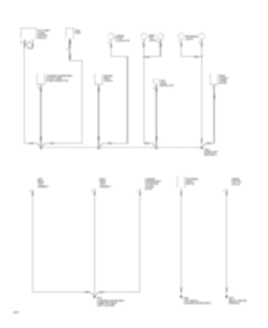
Ground Distribution Wiring Diagram (4 of 4) for Saab Aero 1994 9000
List of elements for Ground Distribution Wiring Diagram (4 of 4) for Saab Aero 1994 9000:
- (below center console)
- (left side of luggage compartment)
- (luggage compartment under left rear light cluster)
- (under left rear seat)
- Airbag control module
- Anti-theft alarm control module
- Fuel pump
- G302
- G304
- G402
- G404
- Heated rear window
- High level brake light
- Left rear light assembly
- License plate illumination
- Luggage compartment lid anti-theft alarm microswitch
- Luggage compartment lid central locking motor
- Motorized aerial switch
- Nca
- Rear fog lights
- Rear window wiper motor
- Reversing lights
- Right rear light assembly
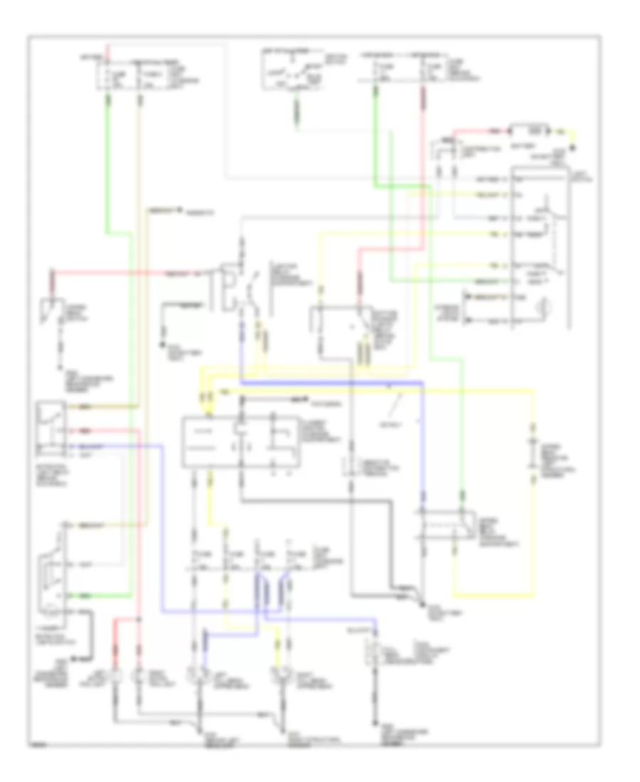
HEADLIGHTS
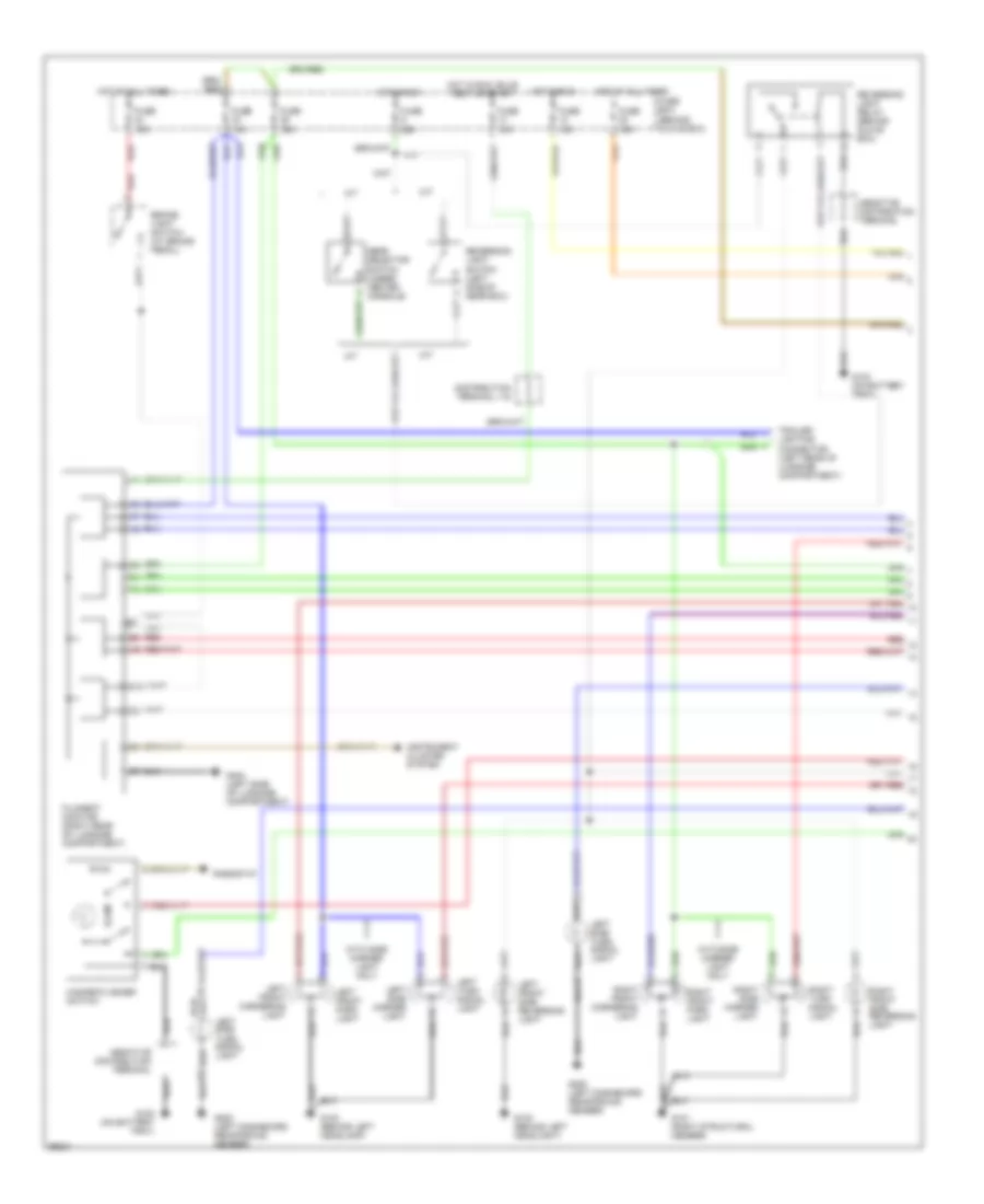
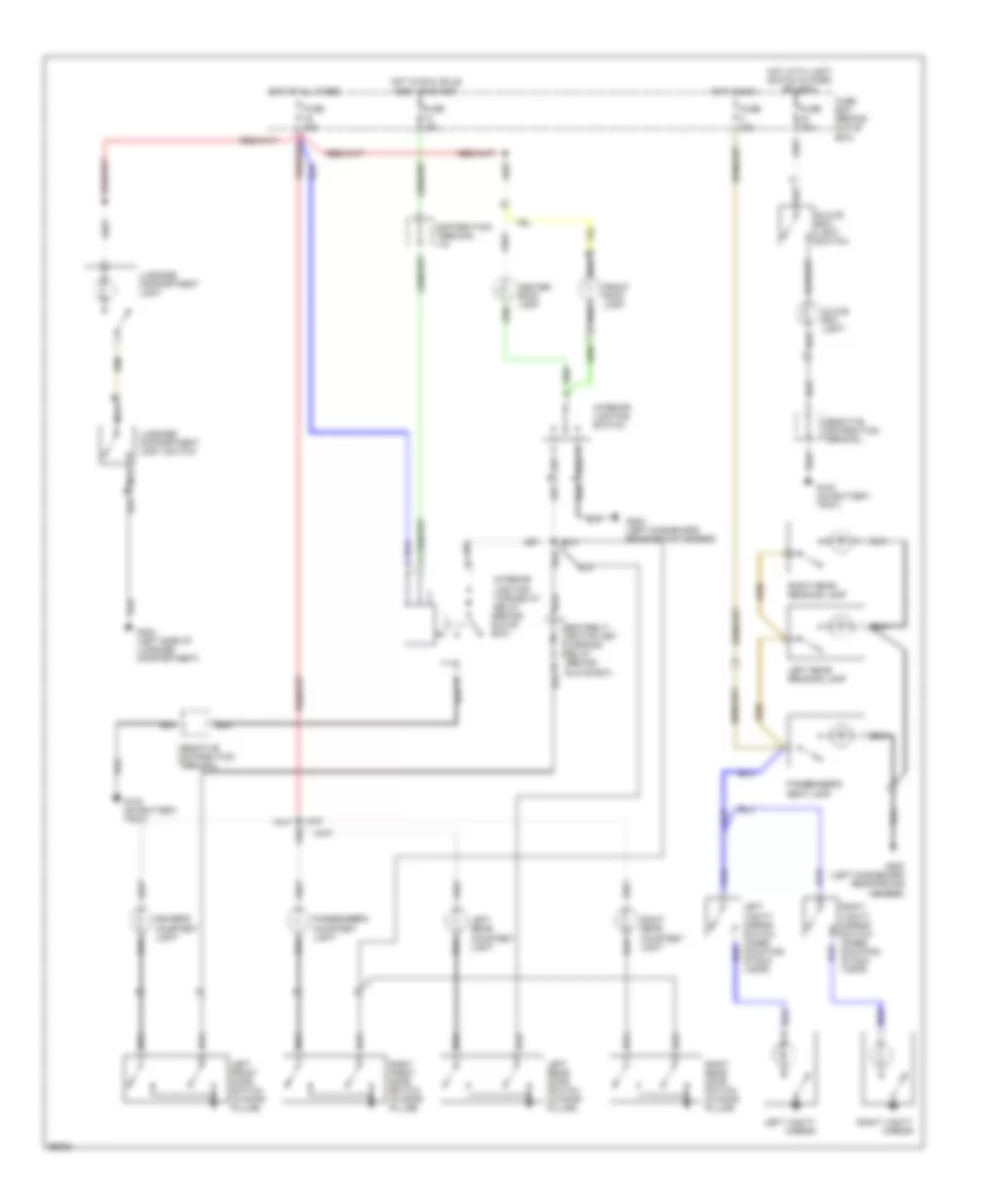
Headlamps Wiring Diagram, with DRL for Saab Aero 1994 9000
List of elements for Headlamps Wiring Diagram, with DRL for Saab Aero 1994 9000:
- 15a
- 58b
- Acc
- Battery
- Bulb test
- Cs only
- Daytime running lights relay (behind glove box)
- Dipped beam relay (in engine compartment)
- Dipped beam resistor (left structural member)
- Dipped beam switch
- Distribution box
- Extra fog light relay (behind glove box)
- Extra fog lights switch
- Filament monitor (in engine compartment)
- Full beam indicator
- Fuse
- Fuse 15a
- Fuse 25a
- Fuse 5
- Fuse box (behind glove box)
- Fuse box (in engine bay)
- G100 (behind left headlamp)
- G101 (right structural member)
- G102 (on battery tray)
- G200 (left dashboard reinforcing member)
- Head
- Hot at all times
- Hot in run
- Ignition switch
- Illum
- Interior lights system
- Left extra fog light
- Left full beam/ dipped beam
- Light switch
- Lighting relay (in engine compartment)
- Lock
- Main instrument display panel
- Off
- Park
- Pictogram
- Red
- Rheostat
- Right extra fog light
- Right full beam/ dipped beam
- Run
- Start
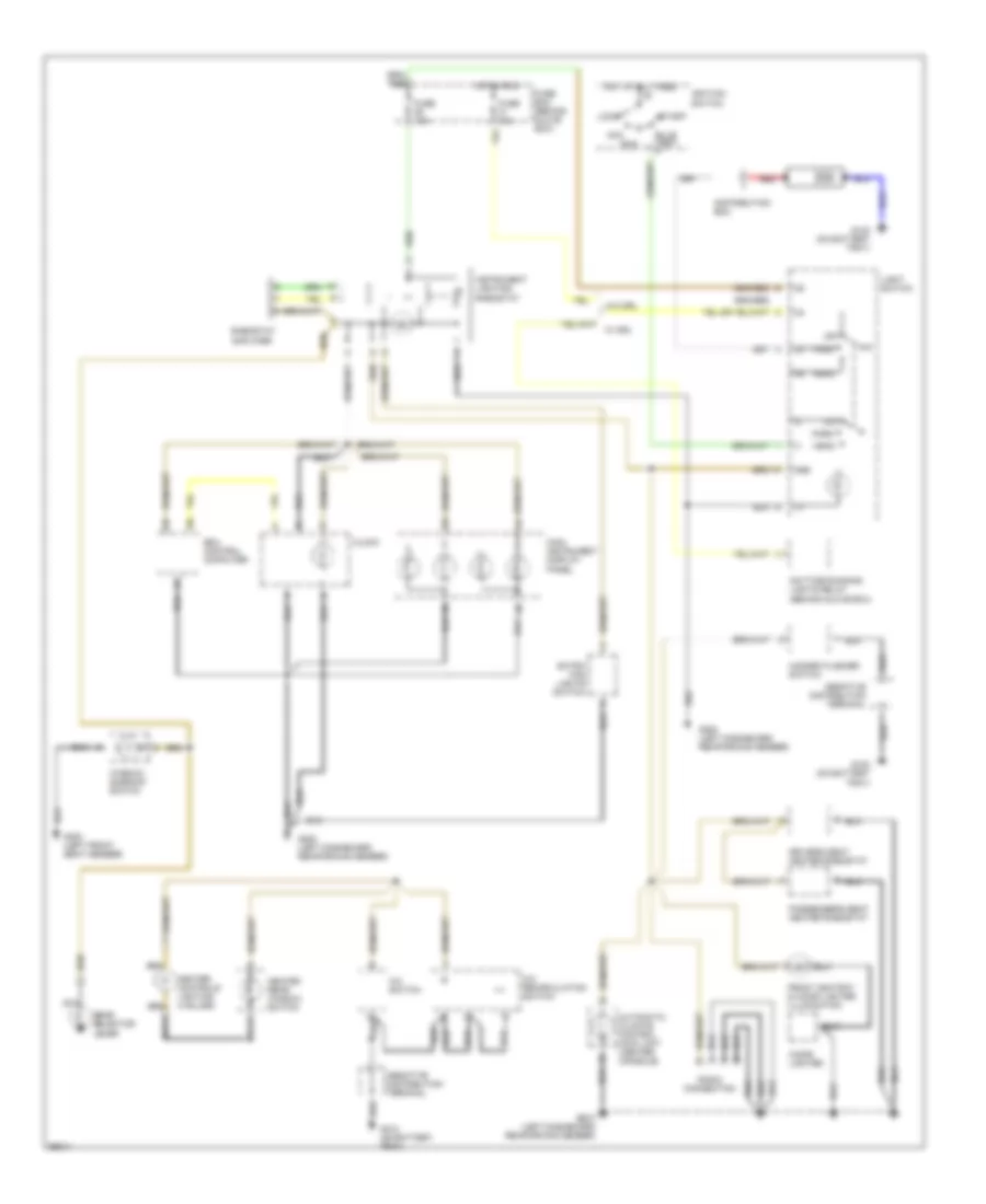
Headlamps Wiring Diagram, without DRL for Saab Aero 1994 9000
List of elements for Headlamps Wiring Diagram, without DRL for Saab Aero 1994 9000:
- (cs)
- 15a
- 58b
- Acc
- Battery
- Bulb test
- Cs only
- Dipped beam relay (in engine compartment)
- Dipped beam resistor (left structural member)
- Dipped beam switch
- Distribution box
- Extra fog light (behind glove box)
- Extra fog lights switch
- Filament monitor (in engine compartment)
- Full beam indicator
- Fuse
- Fuse 15a
- Fuse 25a
- Fuse 5
- Fuse box (behind glove box)
- Fuse box (in engine bay)
- G100 (behind left headlamp)
- G101 (right structural member)
- G102 (on battery tray)
- G200 (left dashboard reinforcing member)
- Head
- Hot at all times
- Hot in run
- Ignition switch
- Illum
- Interior lights system
- Left extra fog light
- Left full beam/ dipped beam
- Light switch
- Lighting relay (in engine compartment)
- Lock
- Main instrument display panel
- Off
- Park
- Pictogram
- Red
- Rheostat
- Right extra fog light
- Right full beam/ dipped beam
- Run
- Start
HORN
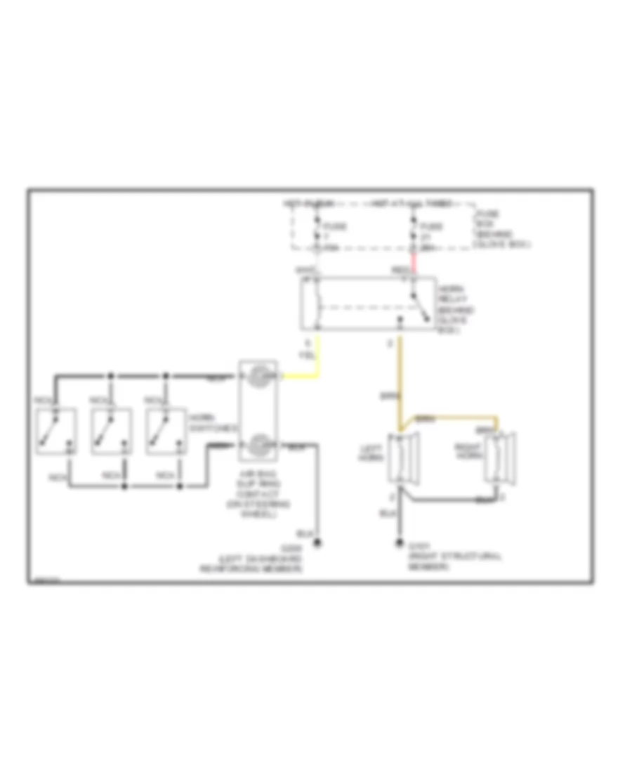
Horn Wiring Diagram for Saab Aero 1994 9000
List of elements for Horn Wiring Diagram for Saab Aero 1994 9000:
- Air bag slip ring contact (on steering wheel)
- Fuse 10a
- Fuse 25a
- Fuse box (behind glove box)
- G101 (right structural member)
- G200 (left dashboard reinforcing member)
- Horn relay (behind glove box)
- Horn switches
- Hot at all times
- Hot in run
- Left horn
- Nca
- Red
- Right horn
INSTRUMENT CLUSTER
EDU Trip Computer & Clock Wiring Diagram for Saab Aero 1994 9000
List of elements for EDU Trip Computer & Clock Wiring Diagram for Saab Aero 1994 9000:
- Air conditioning system
- Clock
- Coolant level switch (in coolant expansion tank)
- Diagnostic test socket (under right front seat)
- Distribution terminal +15
- Edu trip computer (in main instrument display panel)
- Engine control module (left side of engine compartment)
- Fuel gauge
- Fuel level sensor (in fuel tank)
- Fuse 10a
- Fuse 15a
- Fuse box (behind glove box)
- G101 (right structural member)
- G200 (left dashboard reinforcing member)
- G300 (below left front seat)
- Hot at all times
- Hot in run, bulb test or start
- Instrument clusters system (speed sensor)
- Interior lights system (rheostat)
- Low fuel indicator
- Main instrument display panel
- Nca
- Outside temperature sensor (behind left side of front bumper)
- Red
- Selector lever switch
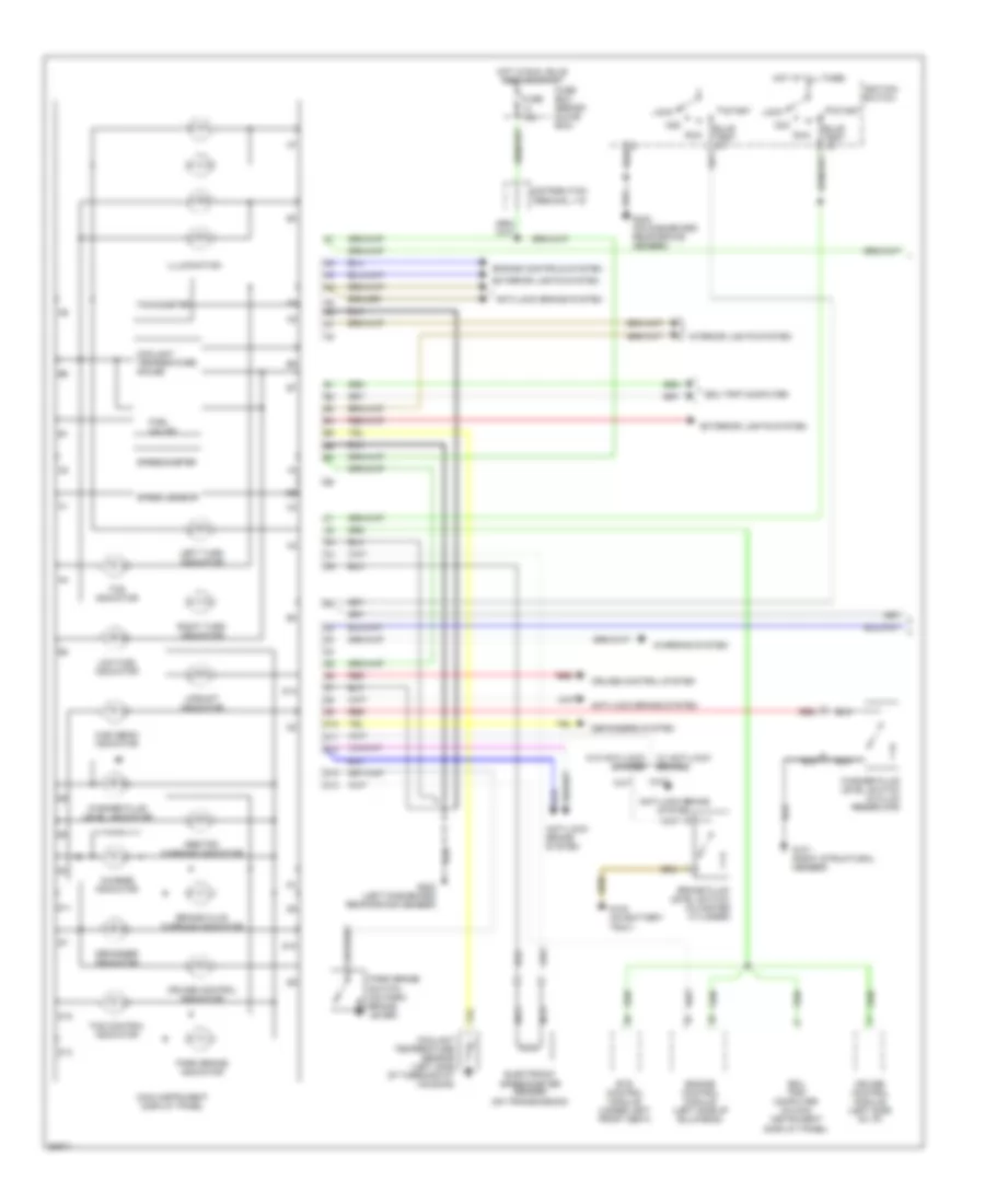
Instrument Cluster & Pictogram Wiring Diagram (1 of 2) for Saab Aero 1994 9000
List of elements for Instrument Cluster & Pictogram Wiring Diagram (1 of 2) for Saab Aero 1994 9000:
- A5 a6
- Abs/tsc warning indicator
- Acc
- Anti-lock brake system
- Brake fluid level switch (in master cylinder)
- Brake fluid warning indicator
- Bulb test
- Charge indicator
- Charging system
- Coolant temperature gauge
- Coolant temperature sensor (left side of thermostat housing)
- Cruise control indicator
- Cruise control module (left side of i/p)
- Cruise control system
- D10
- D11
- D12
- D13
- D14
- Defogger indicator
- Defoggers system
- Distribution terminal +15
- Edu trip computer
- Edu trip computer (in main instrument display panel)
- Electronic speedometer sender (on transmission)
- Engine control module (left side of bulkhead)
- Engine controls system
- Ets control module (under left front seat)
- Exterior lights system
- Fuel
- Fuse 10a
- Fuse box (behind glove box)
- G101 (right structural member)
- G102 (on battery tray)
- G200 (left dashboard reinforcing member)
- G202 (on dashboard reinforcing member)
- Gauge
- High beam indicator
- Hot at all times
- Hot in run, bulb test or start
- Ignition switch
- Illumination
- Interior lights system
- Left turn indicator
- Lock
- Low fuel indicator
- Main instrument display panel
- Nca
- Park brake indicator
- Park brake switch (on park brake lever)
- Red
- Right turn indicator
- Run
- Speed sensor
- Speedometer
- Start
- Tachometer
- Tcs control indicator
- Tcs indicator
- Upshift indicator
- W/ anti-lock brakes
- W/o anti-lock brakes
- Washer fluid level indicator
- Washer fluid level switch (in fluid reservoir)
Instrument Cluster & Pictogram Wiring Diagram (2 of 2) for Saab Aero 1994 9000
List of elements for Instrument Cluster & Pictogram Wiring Diagram (2 of 2) for Saab Aero 1994 9000:
- (brake light
- (high level brake light)
- Air bag indicator
- Airbag control module (below center console)
- Airbag indicator
- B10
- Central light
- Central locking control module (at left kick panel)
- Distri- bution terminal +15
- Driver's door lock indication switch (part of door lock mechanism)
- Engine bay filament monitor (left front corner of engine compartment)
- Exterior
- Exterior lights system
- Exterior lights system (brake lights)
- Exterior lights system (left tail lights)
- Exterior lights system (right tail lights)
- Filament monitor (right rear of luggage compartment)
- Front lights indicator
- Fuse 10a
- Fuse 15a
- Fuse 3 15a
- Fuse 5a
- Fuse box (behind glove box)
- Fuse box (in engine bay)
- G102 (on battery tray)
- G200 (left dashboard reinforcing member)
- G301 (below right front seat)
- G404 (luggage compartment, near left rear light cluster)
- G404 (luggage compt. near left rear light cluster)
- Headlights system (fuse box in engine bay)
- Headlights system (left main/ dipped beam)
- Headlights system (lighting relay)
- Hot in run, bulb test or start
- Hot with lighting switch in park
- Left front door indicator
- Left rear door indicator
- Left rear door lock indication switch (part of door lock mechanism)
- Lights system
- Luggage compartment light switch (luggage compartment lid)
- Luggage lid indicator
- Nca
- Oil pressure indicator
- Oil pressure sensor (front of engine block)
- Passenger's door lock indication switch (part of door lock mechanism)
- Pictogram
- Radio amplifier
- Red
- Right front door indicator
- Right rear door indicator
- Right rear door lock indication switch (part of door lock mechanism)
- Switch)
- Tail lights indicator
INTERIOR LIGHTS
Courtesy Lamp Wiring Diagram for Saab Aero 1994 9000
List of elements for Courtesy Lamp Wiring Diagram for Saab Aero 1994 9000:
- Center roof lamp
- Distribution terminal +15
- Driver's courtesy light
- Front roof lamp
- Fuse 10a
- Fuse 15a
- Fuse box (behind glove box)
- G102 (on battery tray)
- G200 (left dashboard reinforcing member)
- G404 (left side of luggage compartment)
- Glove box light
- Glove box light switch
- Hot at all times
- Hot in run
- Hot in run, bulb test or start
- Hot with light switch in park or head
- Interior lighting switch
- Interior lighting time-delay relay (behind glove box)
- Left front door switch (in door pillar)
- Left rear courtesy light
- Left rear door switch (in door pillar)
- Left rear reading lamp
- Left vanity mirror
- Left vanity mirror switch (inner mounting of sun visor)
- Luggage compartment light
- Luggage compartment light switch
- Nca
- Passenger's courtesy light
- Passenger's seat lamp
- Right front door switch (in door pillar)
- Right rear courtesy light
- Right rear door switch (in door pillar)
- Right rear reading lamp
- Right vanity mirror
- Right vanity mirror switch (inner mounting of sun visor)
- Seatbelt/ ignition key warning relay (behind glove box)
Instrument Illumination Wiring Diagram for Saab Aero 1994 9000
List of elements for Instrument Illumination Wiring Diagram for Saab Aero 1994 9000:
- 58b
- A/c recirculation switch
- A/c switch
- Acc
- Automatic climate control (acc) unit (center console)
- Bulb test x
- Cigar lighter
- Clock
- Daytime running lights relay (behind glove box)
- Distribution box
- Driver's seat heater rheostat
- Edu control computer
- Extra fog lights switch
- Front ashtray & cigar lighter illumination
- Fuse 15a
- Fuse box (behind glove box)
- G102 (on battery tray)
- G200 (left dashboard reinforcing member)
- G300 (left front seat member)
- Gear selector lever
- Hazard flasher switch
- Head
- Heated rear window switch
- Heater controls lighting (4 bulbs)
- Hot at all times
- Hot in run
- Ignition switch
- Instrument lighting rheostat
- Light switch
- Lock
- Main instrument display panel
- Nca
- Off
- Park
- Passenger's seat heater rheostat
- Radio connection
- Red
- Rheostat amplifier
- Run
- Start
- W/o drl
- Window/ sunroof switch
MEMORY SYSTEMS
Memory Seat Wiring Diagram (1 of 2) for Saab Aero 1994 9000
List of elements for Memory Seat Wiring Diagram (1 of 2) for Saab Aero 1994 9000:
- Backward
- C 1995 vftc
- Down
- Drive train data link connector (in engine compartment)
- Edu data link connector (uner right front seat)
- Forward
- Forward/back position sensor (under seat)
- Foward/ back motor (under seat)
- Front height motor (under seat)
- Front height position sensor (under seat)
- Fuse 10a
- Fuse 30a
- Fuse 5a
- Fuse box (behind glove box)
- G300 (left front seat member)
- G301 (right front seat member)
- Hot at all times
- Hot in run
- Left ajustable memory seat control module (below left front seat)
- Left front door switch (in door pillar)
- Left seat memory switch
- Left seat switch
- Rear height motor (under seat)
- Rear height position sensor (under seat)
- Recliner motor (under seat)
- Recliner position sensor (under seat)
- Red
Memory Seat Wiring Diagram (2 of 2) for Saab Aero 1994 9000
List of elements for Memory Seat Wiring Diagram (2 of 2) for Saab Aero 1994 9000:
- Backward
- C 1995 vftc
- Down
- Forward
- Forward/back position sensor (under seat)
- Front height motor (under seat)
- Front height position sensor (under seat)
- Froward/ back motor (under seat)
- Fuse 30a
- Fuse box (behind glove box)
- G301 (right front seat member)
- Hot at all times
- Rear height motor (under seat)
- Rear height position sensor (under seat)
- Recliner motor (under seat)
- Recliner position sensor (under seat)
- Red
- Right adjustable memory seat control module (below left front seat)
- Right front door switch (in door pillar)
- Right seat memory switch
- Right seat switch
POWER ANTENNA
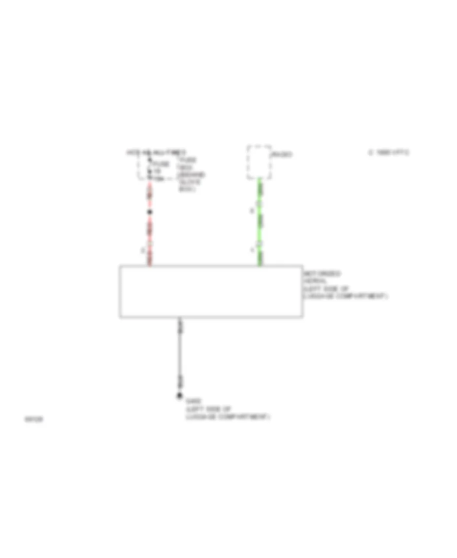
Power Antenna Wiring Diagram for Saab Aero 1994 9000
List of elements for Power Antenna Wiring Diagram for Saab Aero 1994 9000:
- (left side of luggage compartment)
- C 1995 vftc
- Fuse 15a
- Fuse box (behind glove box)
- G402
- Hot at all times
- Motorized aerial
- Radio
- Red
POWER DISTRIBUTION
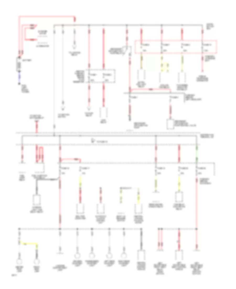
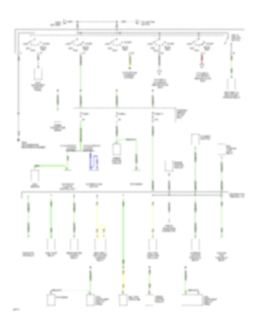
Power Distribution Wiring Diagram (1 of 6) for Saab Aero 1994 9000
List of elements for Power Distribution Wiring Diagram (1 of 6) for Saab Aero 1994 9000:
- 10a
- 15a
- 30a
- 7.5a
- Abs/tcs fuse box (behind brake fluid reservor)
- Alternator
- Automatic climate control unit
- Battery
- Boot lid release switch
- Center roof lamp
- Central locking control module
- Central locking tailgate motor
- Cooling fan relay
- Distri- bution box
- Distribution terminal +30
- Driver's courtesy light
- Edu trip computer
- Extra fog light relay
- Front roof lamp
- Fuel injection main relay
- Fuel pump relay
- Fuse 1
- Fuse 10
- Fuse 16
- Fuse 17
- Fuse 18
- Fuse 2
- Fuse 20
- Fuse 25
- Fuse 5
- Fuse 7
- Fuse 8
- Fuse box (behind glove box)
- Fuse box (behind left headlamp)
- Fuse box (in engine bay)
- G102 (left shock tower)
- Interior light time delay relay
- Left adjustable front seat relay (door switch)
- Left adjustable front seat relay (ignition switch)
- Left adjustable seat control module
- Left rear courtesy light
- Luggage compartment lamp
- Main relay
- Mobile telephone connector
- Nca
- Passenger's courtesy light
- Rear heated window relay
- Red
- Right rear courtesy light
- Secondary air injection pump
- Secondary air injection pump control valve
- Secondary air injection pump relay
- Starter motor
- Time delay cooling fan relay
- To fuse 19
- To ignition switch
- To ignition switch relay
- To lighting relay
- To pump relay
- Two-speed radiator fan relay
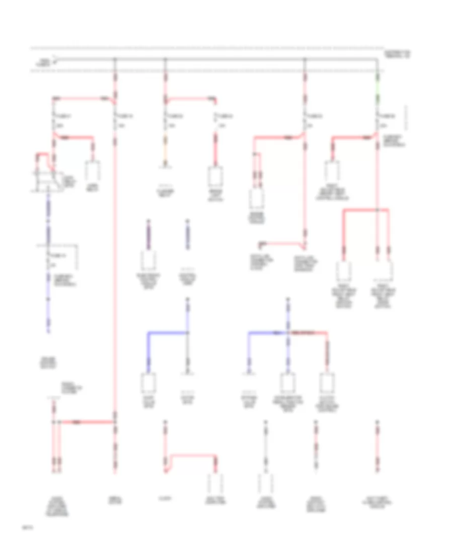
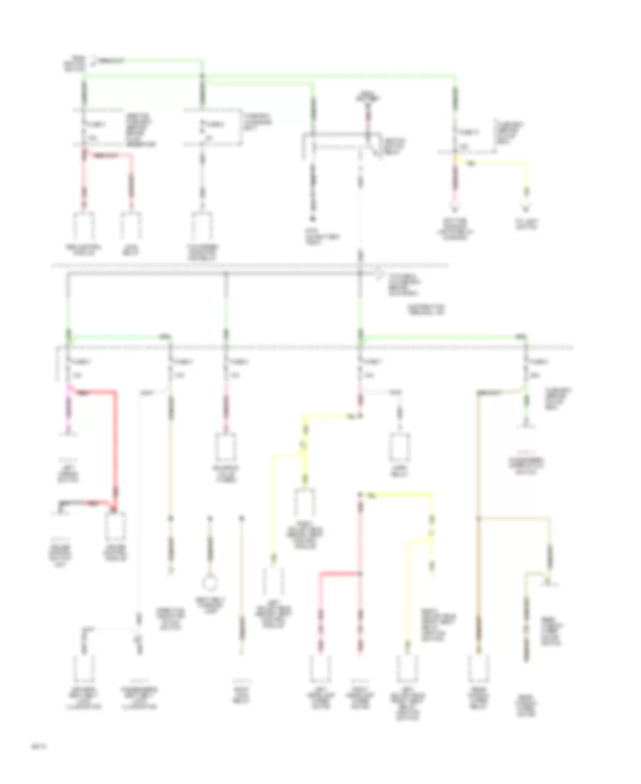
Power Distribution Wiring Diagram (2 of 6) for Saab Aero 1994 9000
List of elements for Power Distribution Wiring Diagram (2 of 6) for Saab Aero 1994 9000:
- 15a
- 25a
- 30a
- Accelerator pedal position sensor (ets)
- Aerial motor
- Anti-theft alarm control module
- Audio system amplifier
- Audio system amplifier (w/ mobile telephone)
- Brake light switch
- Bypass valve (ets)
- Clock
- Clutch switch (for cruise control)
- Control module (asr)
- Cruise control switch
- Data link connector (for edu & acc)
- Data link connector (for tran- smission)
- Distribution terminal +30
- Dump valve (ets)
- Electronic control module (ets)
- Engine control module
- Flasher relay
- From e fuse16
- Fuse 15
- Fuse 16
- Fuse 21
- Fuse 22
- Fuse 23
- Fuse 24
- Fuse 26
- Fuse box (behind glove box)
- Horn relay
- Main relay (ets)
- Motor (ets)
- Radio contact box with amplifier
- Radio/ cassette player
- Red
- Right adjustable front seat relay (door switch)
- Right adjustable front seat relay (ignition switch)
- Right adjustable memory seat control module
- Scc trip computer
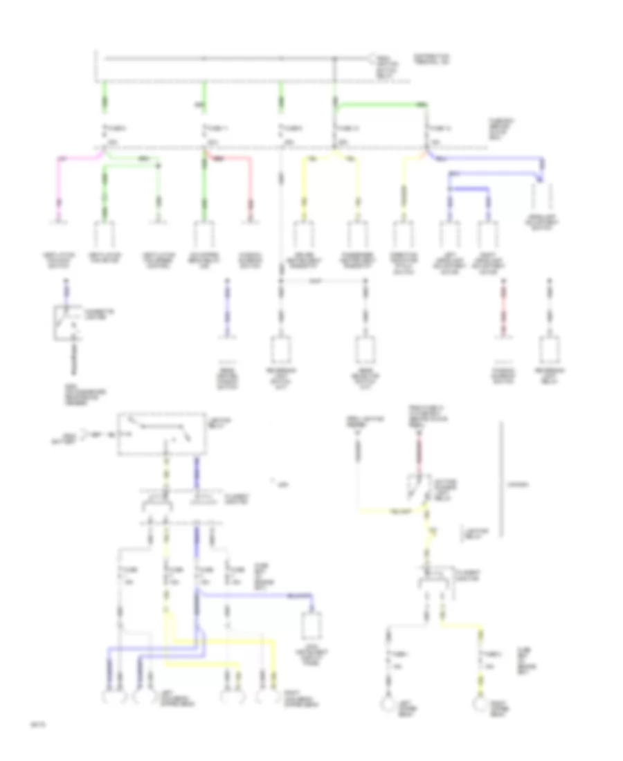
Power Distribution Wiring Diagram (3 of 6) for Saab Aero 1994 9000
List of elements for Power Distribution Wiring Diagram (3 of 6) for Saab Aero 1994 9000:
- 10a
- A/c recycling switch
- Acc
- Airbag control module
- Automatic climate control unit
- Bulb test
- Cooling fan time delay relay
- Distribution terminal +15
- Edu trip computer
- Engine control module
- Exh warning lamp relay
- Filament monitor
- From battery
- Fuel pump relay
- Fuse 1
- Fuse 13
- Fuse 4
- Fuse box (behind glove box)
- G202 (on dashboard reinforcing member)
- Interior lighting time delay relay
- Key in ignition switch
- Lock
- Main instrument display panel
- Mobile telephone connector
- Pictogram
- Radiator fan relay
- Rear heated window relay
- Red
- Run
- Scc trip computer or clock
- Seat belt/ ignition key warning relay
- Seat-belt & ignition key warning relay
- Speed transmitter sesor
- Start
- Sun sensor
- To fuse 27, in fuse box (behind glove box)
- To fuse 31, in fuse box (behind glove box)
- To lighting switch
- To starting/ charging system
- W/ automatic climate control
- W/o automatic climate control
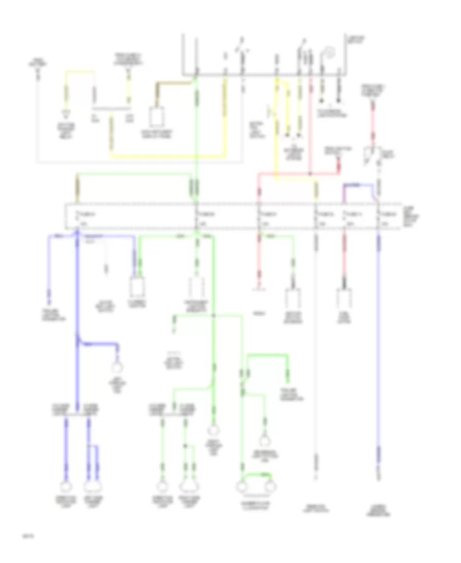
Power Distribution Wiring Diagram (4 of 6) for Saab Aero 1994 9000
List of elements for Power Distribution Wiring Diagram (4 of 6) for Saab Aero 1994 9000:
- 10a
- 15a
- 20a
- Abs control module
- Abs/tcs fuse box (behind brake fluid reservor)
- Cruise control module
- Cruise control switch (m/t)
- Daytime running lights relay (canada)
- Direction indicator stalk switch
- Distribution terminal +54
- Driver's seat belt lock illumination
- From battery
- From ignition h
- Fuse 2
- Fuse 3
- Fuse 31
- Fuse 5
- Fuse 6
- Fuse 7
- Fuse 8
- Fuse box (behind glove box)
- Fuse box (in engine bay)
- G102 (on battery tray)
- Horn relay
- Ignition switch relay
- Left adjustable front seat relay (ignition switch)
- Left adjustable memory seat control module
- Left headlamp wiper motor
- Left mirror switch
- Main relay
- Passenger's seat belt lock illumination
- Rear window wiper motor
- Rear window wiper motor switch
- Rear window wiper relay
- Red
- Right adjustable front seat relay (ignition switch)
- Right adjustable memory seat control module
- Right headlamp wiper motor
- Seat belt warning lamp
- Shift lock relay
- Solenoid valve (turbo)
- Switch
- To fuse 9, in fuse box behind glove box
- To light switch
- Two-speed radiator fan relay
- Windscreen wiper stalk switch
Power Distribution Wiring Diagram (5 of 6) for Saab Aero 1994 9000
List of elements for Power Distribution Wiring Diagram (5 of 6) for Saab Aero 1994 9000:
- 15a
- 25a
- 30a
- Battery
- Canada
- Cigarette lighter
- Daytime running light relay
- Dim dipped beam relay (cs)
- Direction indicator stalk switch
- Distribution terminal +54
- Driver heated seat rheostat
- Filament monitor
- From fuse 31, in fuse box (behind glove box)
- From ignition switch relay
- From j
- From lighting switch
- Fuse
- Fuse 1
- Fuse 10
- Fuse 11
- Fuse 12
- Fuse 2
- Fuse 6
- Fuse 9
- Fuse box (behind glove box)
- Fuse box (in engine bay)
- G202 (on dashboard reinforcing member)
- Gear selector switch (a/t)
- Headlamp adjustment switch
- Left dipped beam
- Left headlamp adjustment motor
- Left main beam/ dipped beam
- Lighting relay
- Main instrument display panel
- Passenger heated seat rheostat
- Rear heated window switch
- Red
- Reversing light relay
- Reversing light switch (m/t)
- Right dipped beam
- Right headlamp adjustment motor
- Right main beam/ dipped beam
- Usa
- Ventilation fan main switch
- Ventilation fan motor
- Ventilation fan speed control
- Window/ sunroof switch
Power Distribution Wiring Diagram (6 of 6) for Saab Aero 1994 9000
List of elements for Power Distribution Wiring Diagram (6 of 6) for Saab Aero 1994 9000:
- 10a
- 15a
- 20a
- 58b
- Daytime running light relay
- Direction indicator lamp
- Extra fog light switch
- Filament monitor
- From battery
- From fuse 1, in abs/tcs fuse box
- From fuse 31, in fuse box (in engine bay)
- From ignition switch
- Fuel pump motor
- Fuse 14
- Fuse 27
- Fuse 28
- Fuse 29
- Fuse 30
- Fuse 32
- Fuse box (behind glove box)
- Glove box light switch
- Head
- Ignition switch solenoid
- Instrument lighting rheostat
- Lambda sensor preheater
- Left parking light (cs)
- Left side marker light
- Lighting switch
- Main instument display panel
- Nca
- Number plate illumination
- Off
- Park
- Pump relay
- Radio
- Rear fog light switch
- Red
- Reversing light fitting (cs)
- Right parking light (cs)
- Right side marker light
- To exterior lights system
- To interior lights system
- Trailer lighting connector
- W/ dlr
- W/ side marker lights
- W/o dlr
- W/o side marker lights
POWER DOOR LOCKS
Power Door Lock Wiring Diagram for Saab Aero 1994 9000
List of elements for Power Door Lock Wiring Diagram for Saab Aero 1994 9000:
- (left side of i/p)
- C 1995 vftc
- Central locking
- Control module
- Door lock switch (part of window/ sunroof switch)
- Driver's door lock indication switch (part of door lock mechanism)
- Driver's door lock microswitch (at lock cylinder)
- Driver's door lock motor
- Fuel door lock motor
- Fuse 15a
- Fuse box (behind glove box)
- G102 (on battery tray)
- G200 (left dashboard reinforcing member)
- G300 (below left front seat)
- Hot at all times
- Left rear door lock motor
- Passenger's door lock microswitch (at lock cylinder)
- Passenger's door lock motor
- Pictogram
- Red
- Right rear door lock motor
POWER MIRRORS
Power Mirror Wiring Diagram for Saab Aero 1994 9000
List of elements for Power Mirror Wiring Diagram for Saab Aero 1994 9000:
- 1995 vftc c
- Defoggers system
- Electrically operated door mirror switch
- Fuse 10a
- Fuse box (behind glove box)
- G102 (on battery tray)
- G200 (left dashboard reinforcing member)
- Heating element
- Hot in run
- Left door electrically operated door mirror
- Motor
- Right door electrically operated door mirror
POWER SEATS
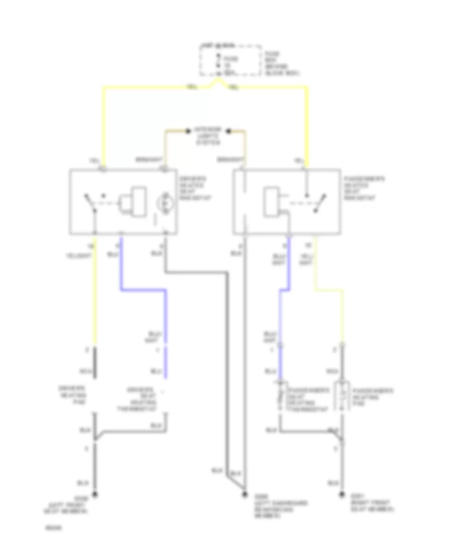
Heated Seats Wiring Diagram for Saab Aero 1994 9000
List of elements for Heated Seats Wiring Diagram for Saab Aero 1994 9000:
- (left front
- Driver's
- Driver's heated seat rheostat
- Fuse 25a
- Fuse box (behind glove box)
- G200 (left dashboard reinforcing member)
- G300
- G301 (right front seat member)
- Heating
- Hot in run
- Interior lights system
- Nca
- Pad
- Passenger's heated seat rheostat
- Passenger's heating pad
- Passenger's seat heating thermostat
- Seat
- Seat member)
- Thermostat
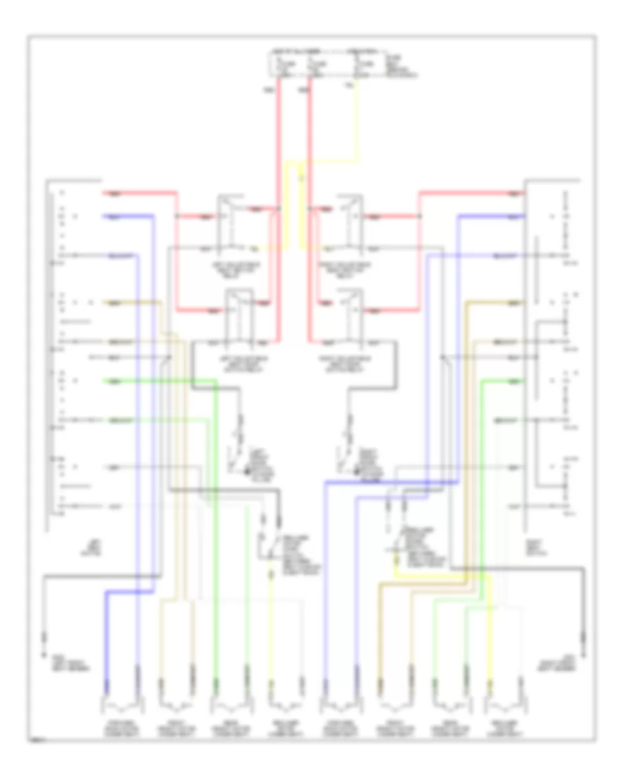
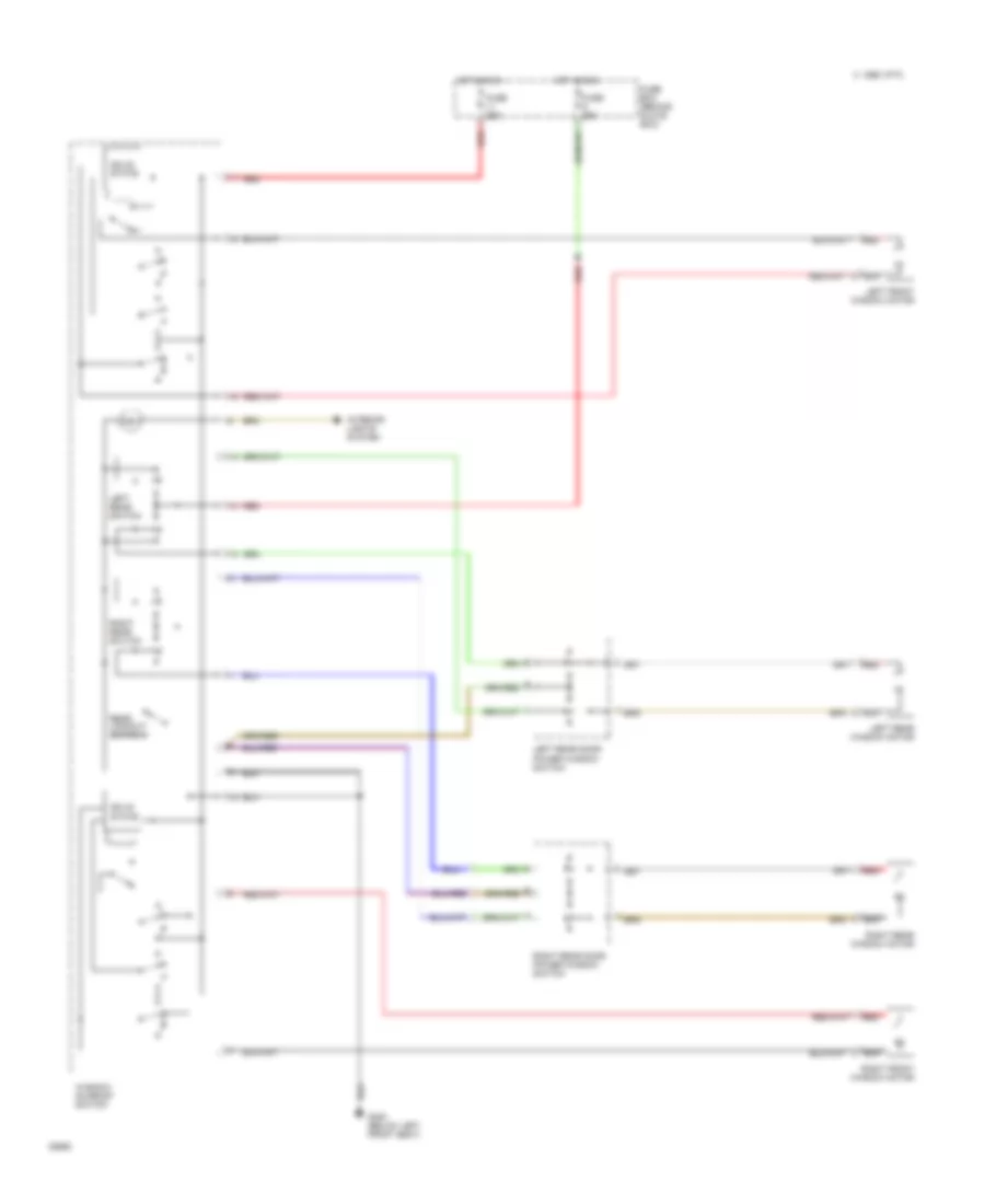
Power Seats Wiring Diagram for Saab Aero 1994 9000
List of elements for Power Seats Wiring Diagram for Saab Aero 1994 9000:
- Forward/ back motor (under seat)
- Front height motor (under seat)
- Fuse 10a
- Fuse 30a
- Fuse box (behind glove box)
- G300 (left front seat member)
- G301 (right front seat member)
- Hot at all times
- Hot in run
- Left adjustable seat door switch relay
- Left adjustable seat ignition
- Left front door switch (in door pillar)
- Left seat switch
- Rear height motor (under seat)
- Recliner motor (under seat)
- Recliner motor micro switch (between seat cushion & seat back)
- Red
- Relay
- Right adjustable seat door switch relay
- Right adjustable seat ignition relay
- Right front door switch (in door pillar)
- Right seat switch
POWER TOP/SUNROOF
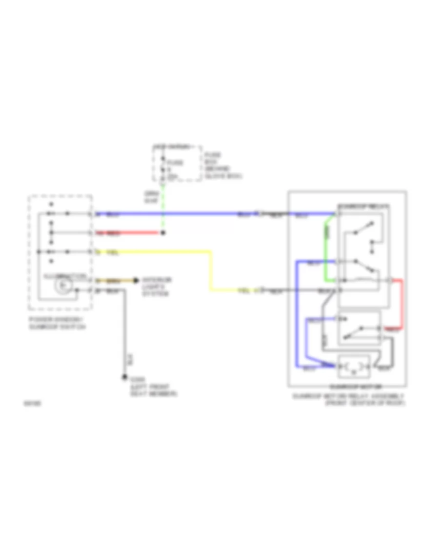
Sunroof Wiring Diagram for Saab Aero 1994 9000
List of elements for Sunroof Wiring Diagram for Saab Aero 1994 9000:
- Fuse 25a
- Fuse box (behind glove box)
- G300 (left front seat member)
- Hot in run
- Illumination
- Interior lights system
- Nca
- Power window/ sunroof switch
- Red
- Sunroof motor
- Sunroof motor/ relay assembly (front center of roof)
- Sunroof relay
POWER WINDOWS
Power Window Wiring Diagram for Saab Aero 1994 9000
List of elements for Power Window Wiring Diagram for Saab Aero 1994 9000:
- C 1995 vftc
- Fuse 25a
- Fuse box (behind glove box)
- G300 (below left front seat)
- Hot in run
- Interior lights system
- Left front window motor
- Left rear door power window switch
- Left rear switch
- Left rear window motor
- Rear lockout switch
- Red
- Right front window motor
- Right rear door power window switch
- Right rear switch
- Right rear window motor
- Solid state
- Window/ sunroof switch
RADIO
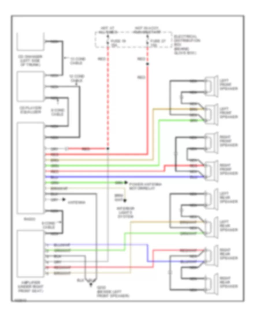
Radio Wiring Diagrams for Saab Aero 1994 9000
List of elements for Radio Wiring Diagrams for Saab Aero 1994 9000:
- 12 cond cable
- 13 cond cable
- 8 cond cable
- Amplifier (under right front seat)
- Antenna
- Cd changer (left side of trunk)
- Cd player/ equalizer
- Electrical distribution box (behind glove box)
- Fuse 19 15a
- Fuse 27 10a
- G202 (beside left front speaker)
- Hot at all times
- Hot in accy, run or start
- Interior lights system
- Left front speaker
- Left rear speaker
- Nca
- Power antenna motor/relay
- Radio
- Red
- Right front speaker
- Right rear speaker
SHIFT INTERLOCKS
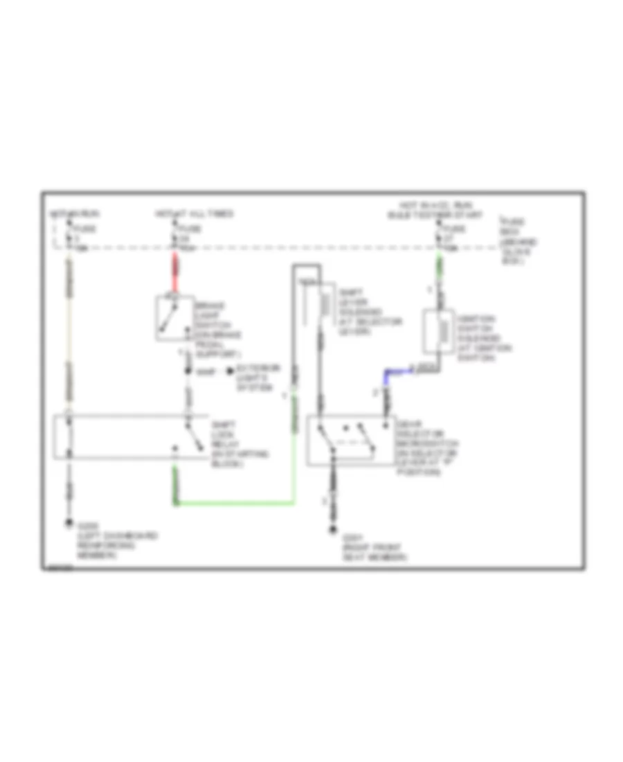
Shift Interlock Wiring Diagram for Saab Aero 1994 9000
List of elements for Shift Interlock Wiring Diagram for Saab Aero 1994 9000:
- Exterior lights system
- Fuse 10a
- Fuse 15a
- Fuse box (behind glove box)
- G200 (left dashboard reinforcing member)
- G301 (right front seat member)
- Gear selector microswitch (in selector lever at "p" position)
- Hot at all times
- Hot in acc, run bulb test or start
- Hot in run
- Ignition switch solenoid (at ignition switch)
- Nca
- Red
- Shift lever solenoid (at selector lever)
- Shift lock relay (in starting block)
STARTING/CHARGING
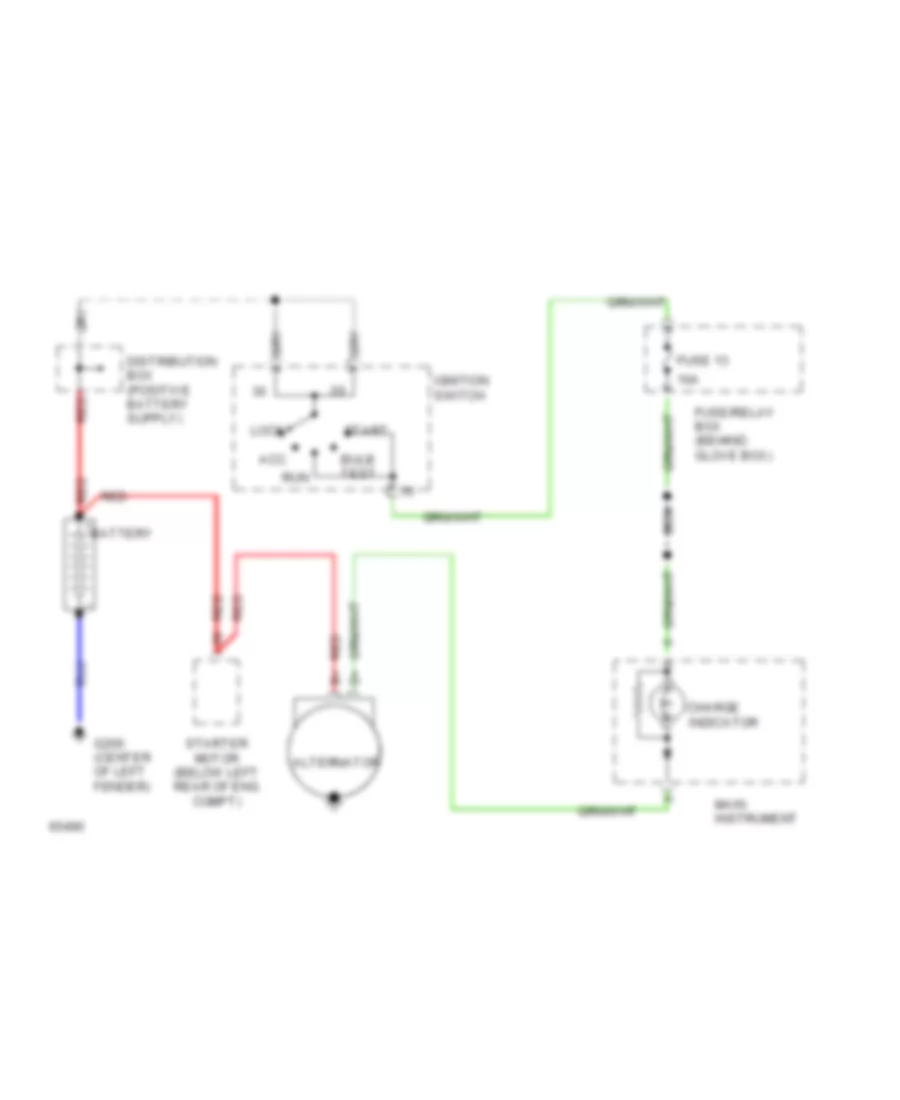
Charging Wiring Diagram for Saab Aero 1994 9000
List of elements for Charging Wiring Diagram for Saab Aero 1994 9000:
- 10a
- Acc
- Alternator
- Battery
- Bulb test
- Charge indicator
- Fuse 13
- Fuse/relay box (behind glove box)
- G200 (center of left fender)
- Ignition switch
- Lock
- Main instrument
- Red
- Run
- Start
- Starter motor (below left rear of eng compt)
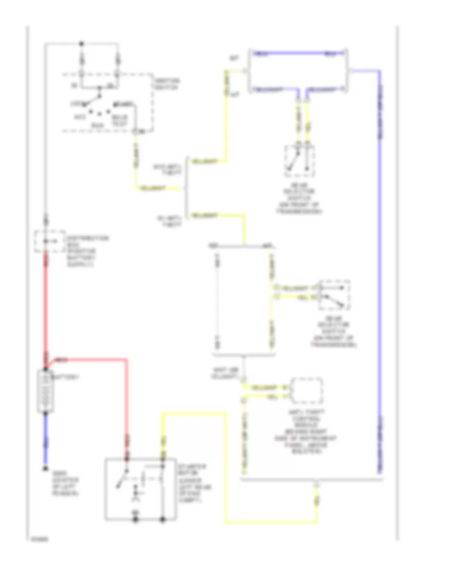
Starting Wiring Diagram for Saab Aero 1994 9000
List of elements for Starting Wiring Diagram for Saab Aero 1994 9000:
- (lower left rear of eng compt)
- A/t
- Acc
- Anti- theft control module (behind right side of instrument panel, above bolster)
- Battery
- Bulb test
- G200 (center of left fender)
- Gear selector switch (on front of transmission)
- Ignition switch
- Lock
- M/t
- Red
- Run
- Start
- Starter motor
- W/ anti- theft
- W/o anti- theft
SUPPLEMENTAL RESTRAINTS
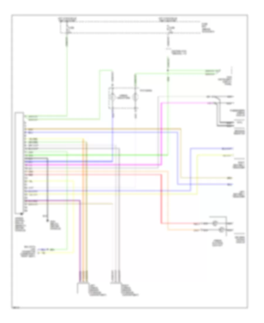
Supplemental Restraint Wiring Diagram for Saab Aero 1994 9000
List of elements for Supplemental Restraint Wiring Diagram for Saab Aero 1994 9000:
- (behind glove box)
- Air bag control module (beneath center console)
- Airbag indicators
- Airbag slip ring contact
- Bridging resistor
- Distribution terminal +15
- Driver's air bag module
- Edu data link connector (under right front seat)
- Fuse 10a
- Fuse 5a
- Fuse box
- G302 (below center console)
- Hot in run bulb test or start
- Left airbag sensor (in engine compartment)
- Left seatbelt tensioner
- Main instrument display panel
- Nca
- Passenger's airbag module
- Pictogram
- Red
- Right airbag sensor (in engine compartment)
- Right seatbelt tensioner
TRUNK, TAILGATE, FUEL DOOR
Trunk & Fuel Door Release Wiring Diagram for Saab Aero 1994 9000
List of elements for Trunk & Fuel Door Release Wiring Diagram for Saab Aero 1994 9000:
- Anti-theft alarm control module (right side of i/p)
- Central locking control module (left side of i/p)
- Door locks system
- Fuel door lock motor
- Fuse 10a
- Fuse 15a
- Fuse box (behind glove box)
- G200 (left dashboard reinforcing member)
- G404 (left side of lugggage compartment)
- Hot at all times
- Luggage compartment lid release switch
- Luggage compartment lock motor (in tailgate)
WARNING SYSTEMS
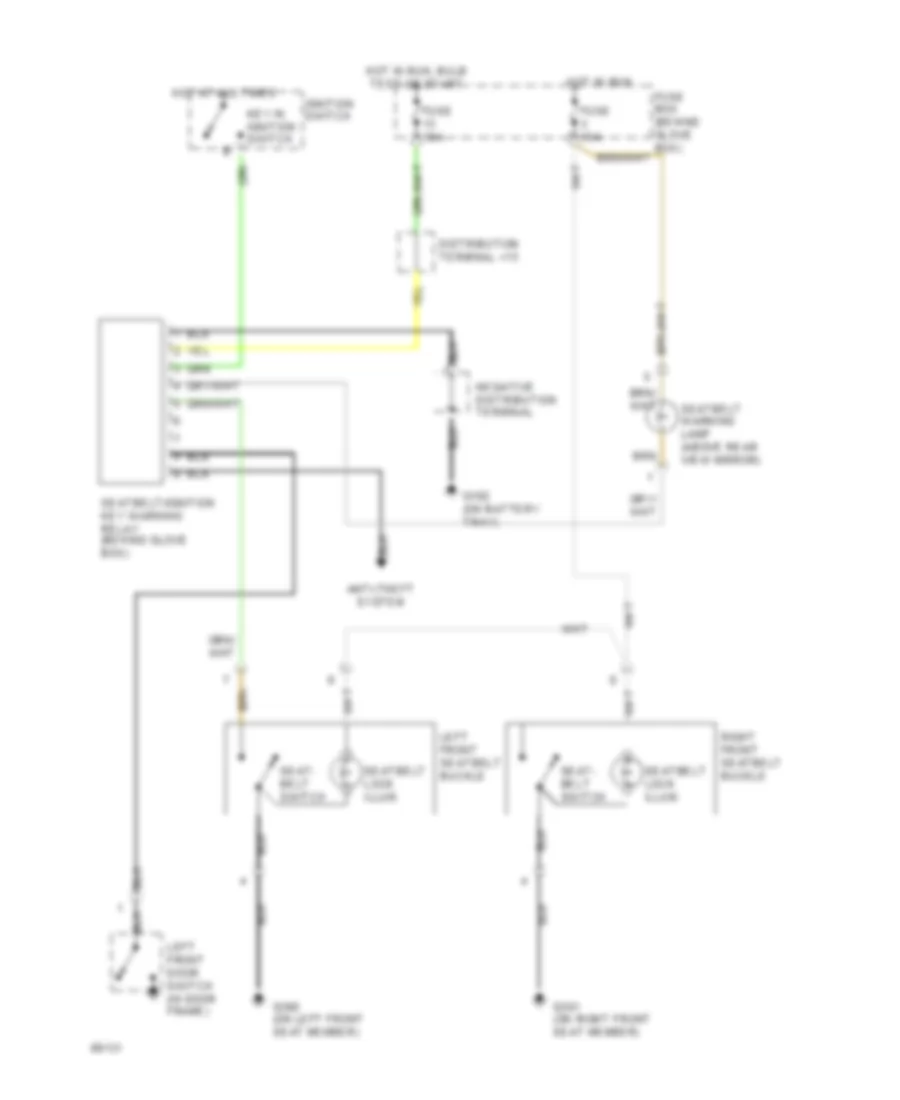
Warning System Wiring Diagrams for Saab Aero 1994 9000
List of elements for Warning System Wiring Diagrams for Saab Aero 1994 9000:
- Anti-theft system
- Distribution terminal +15
- Fuse 10a
- G102 (on battery tray)
- G300 (on left front seat member)
- G301 (on right front seat member)
- Hot at all times
- Hot in run
- Hot in run, bulb test or start
- Ignition switch
- Key in ignition switch
- Left front door switch (in door frame)
- Left front seatbelt buckle
- Right front seatbelt buckle
- Seat- belt switch
- Seatbelt lock illum.
- Seatbelt warning lamp (above rear view mirror)
- Seatbelt/ignition key warning relay (behind glove box)
WIPER/WASHER
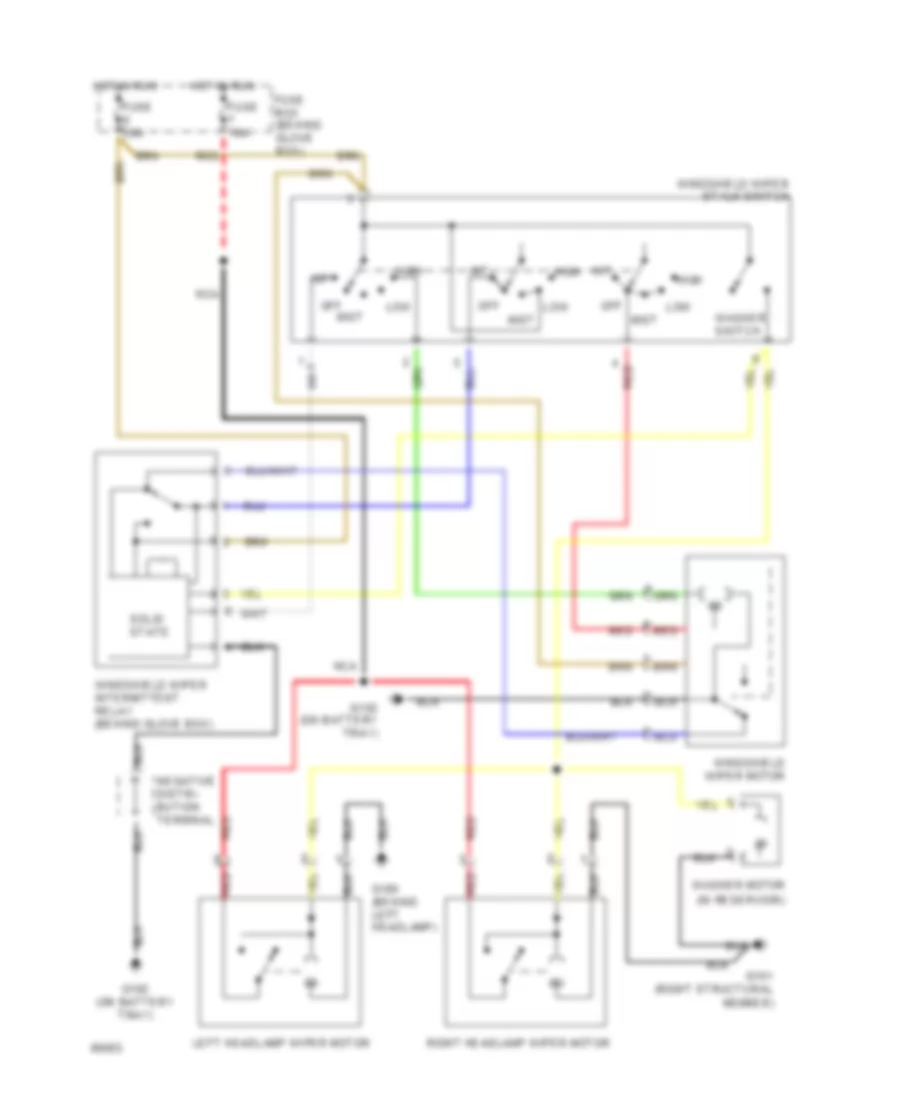
Front Wiper/Washer & Headlamp Washer/Wiper Wiring Diagram for Saab Aero 1994 9000
List of elements for Front Wiper/Washer & Headlamp Washer/Wiper Wiring Diagram for Saab Aero 1994 9000:
- (in reservoir)
- Fuse 10a
- Fuse 20a
- Fuse box (behind glove box)
- G100 (behind left headlamp)
- G101 (right structural member)
- G102 (on battery tray)
- High
- Hot in run
- Int
- Left headlamp wiper motor
- Low
- Mist
- Nca
- Off
- Red
- Right headlamp wiper motor
- Solid state
- Stalk switch
- Washer motor
- Washer switch
- Windshield wiper
- Windshield wiper intermittent relay (behind glove box)
- Windshield wiper motor
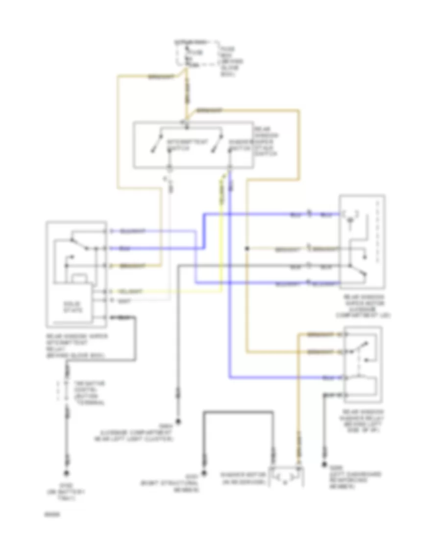
Rear Wiper/Washer Wiring Diagram for Saab Aero 1994 9000
List of elements for Rear Wiper/Washer Wiring Diagram for Saab Aero 1994 9000:
- (behind left side of i/p)
- (in reservoir)
- (luggage compartment lid)
- Fuse 20a
- Fuse box (behind glove box)
- G101 (right structural
- G102 (on battery tray)
- G200 (left dashboard reinforcing member)
- G404 (luggage compartment near left light cluster)
- Hot in run
- Intermittent switch
- Member)
- Rear window washer relay
- Rear window wiper intermittent relay (behind glove box)
- Rear window wiper motor
- Rear window wiper stalk switch
- Solid state
- Washer motor
- Washer switch

 Čeština
 Dansk
Dansk Deutsch
 Ελληνικά
 English
 English
 Español
 Suomi
Suomi Français
 Français
 עברית
עברית Hrvatski
 Magyar
 Italiano
 日本語
日本語 한국어
한국어 Polski
 Português
 Português
 Română
 Русский
 Slovenčina
 Slovenščina
 Svenska
 Türkçe
 中文 (中国)