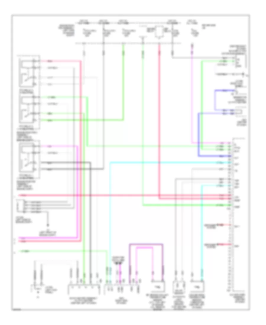
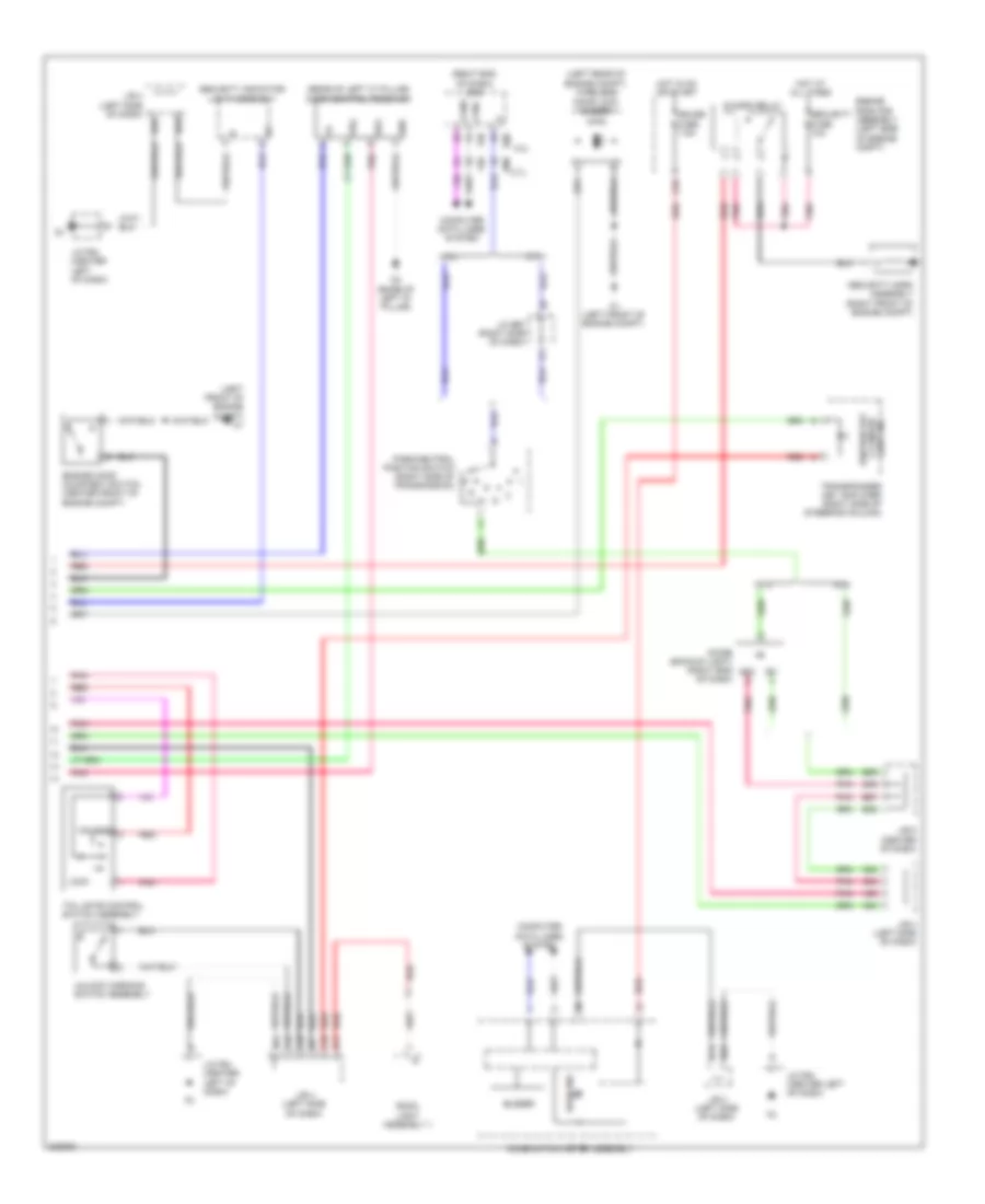
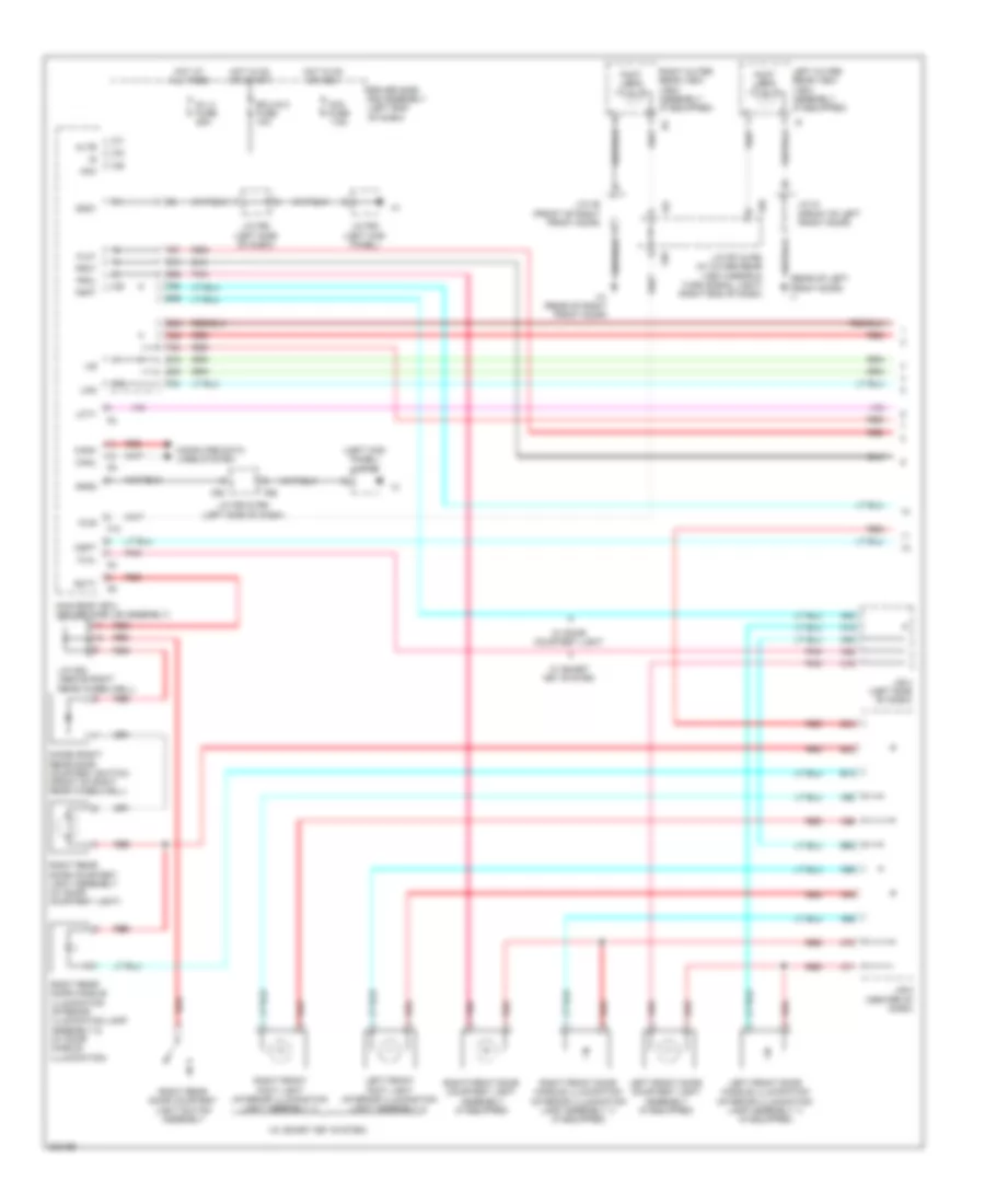
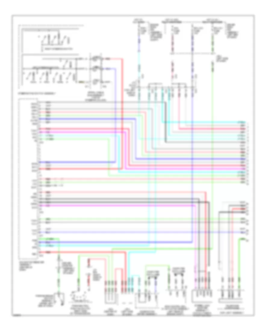
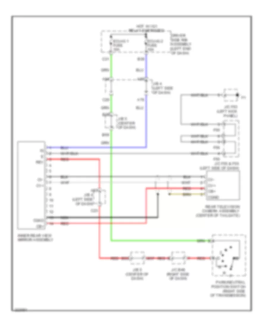
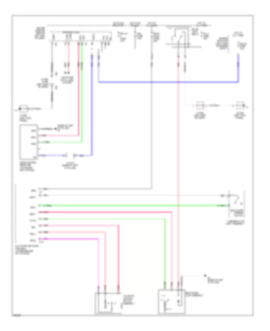
AIR CONDITIONING
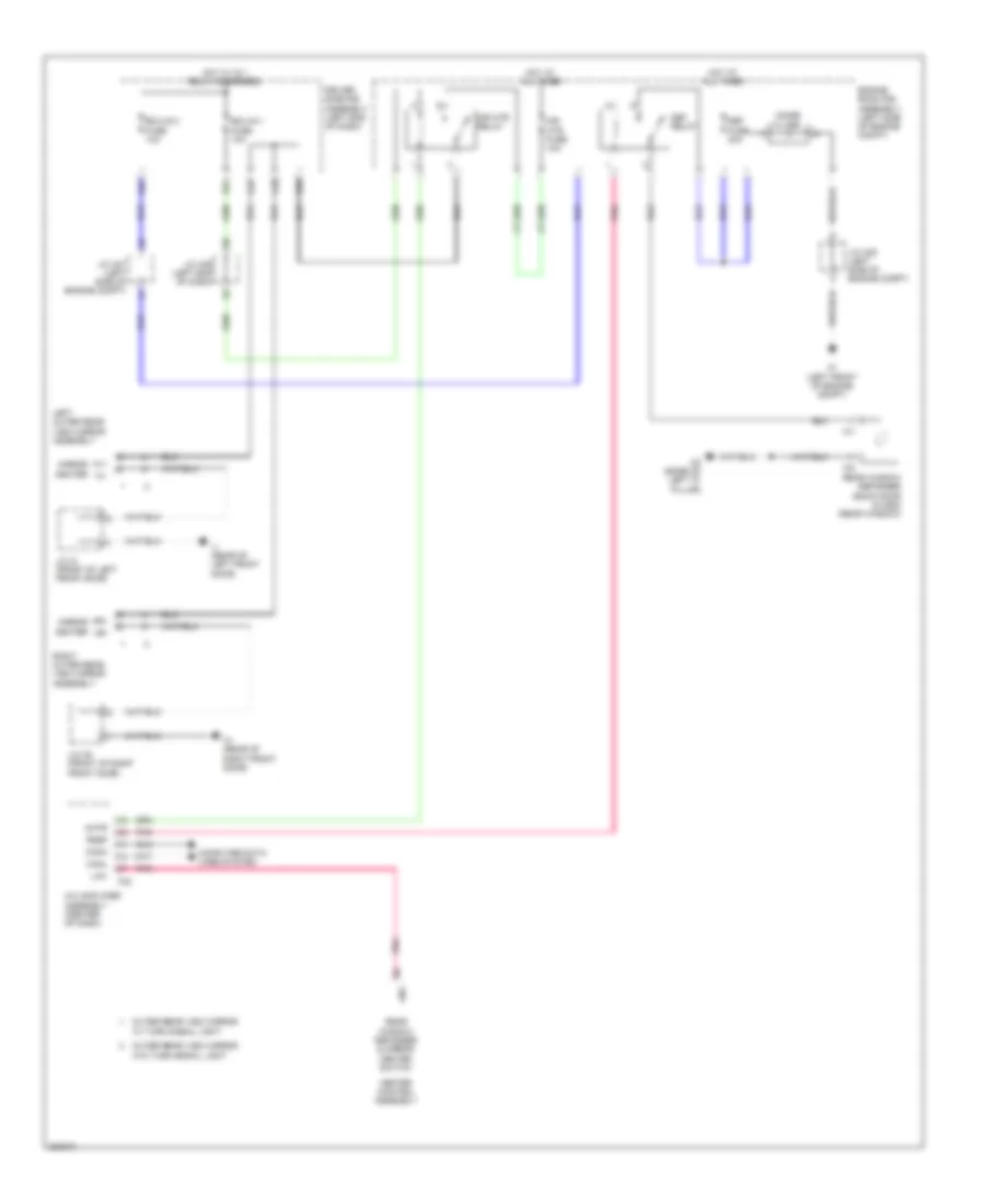
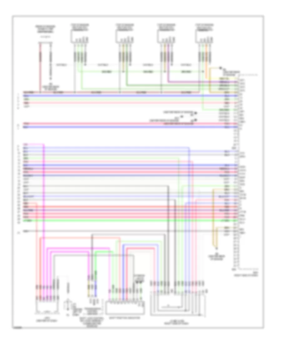
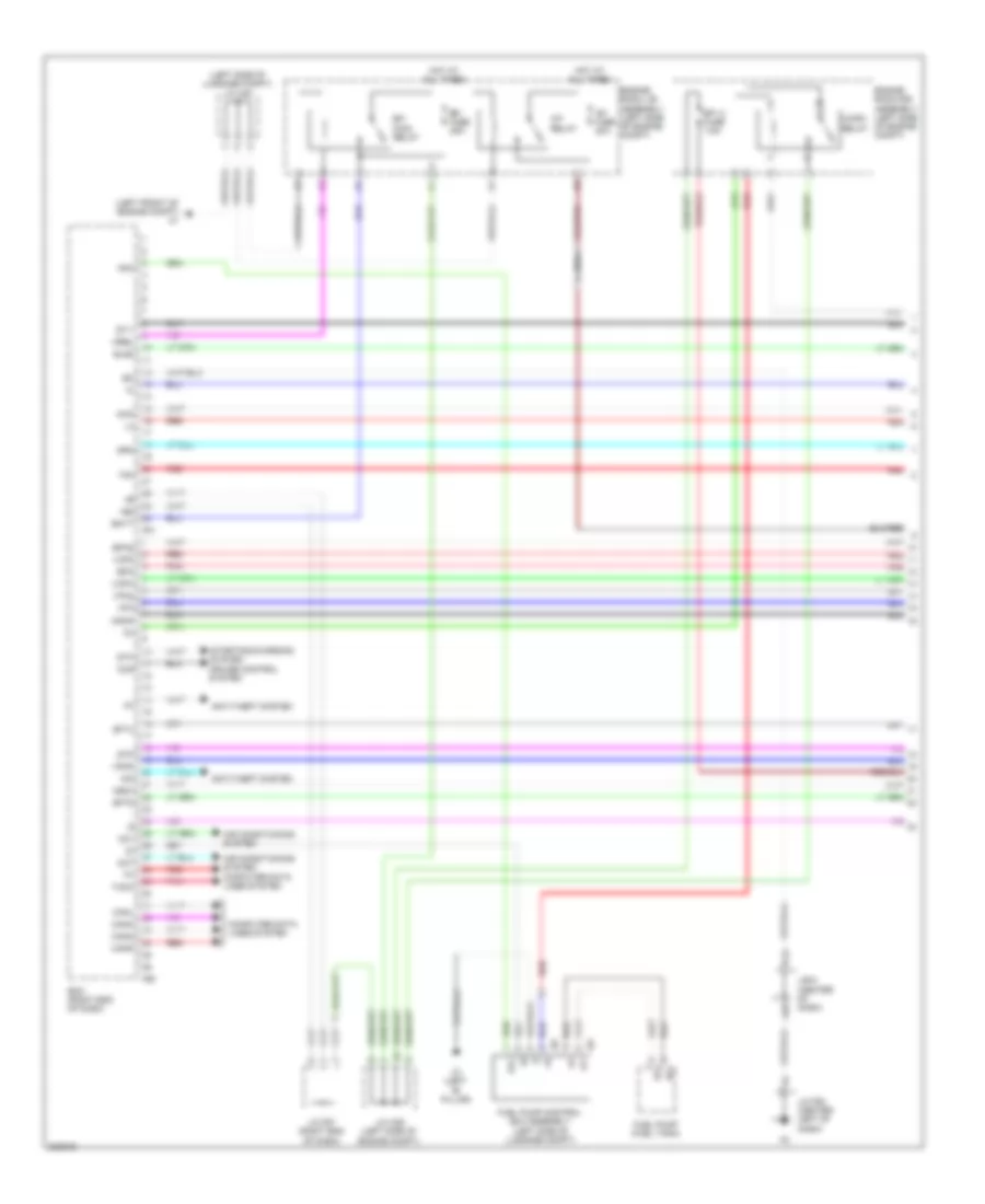
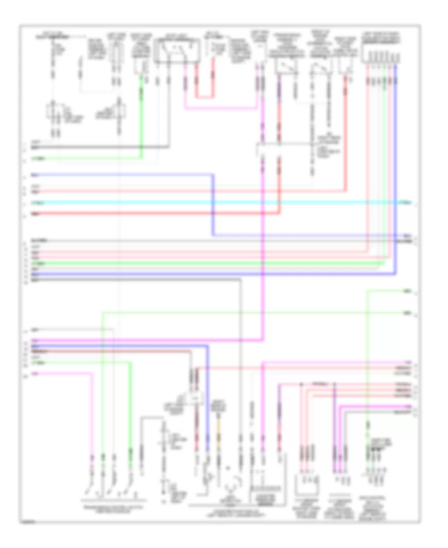
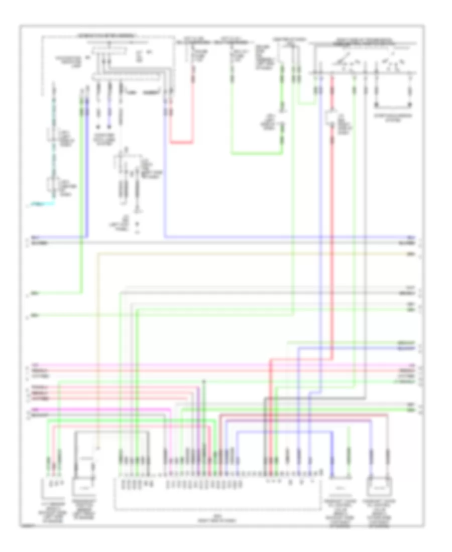
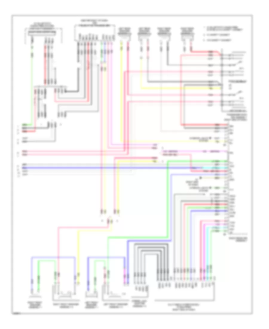
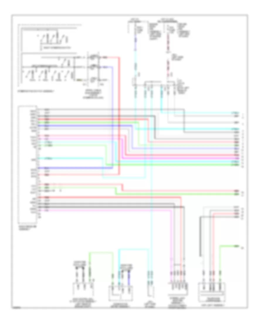
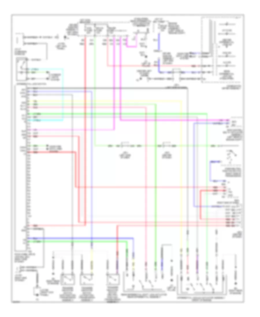
Automatic A/C Wiring Diagram (1 of 2) for Toyota 4Runner Trail 2010
 https://portal-diagnostov.com/license.html
Automotive Electricians Portal FZCO
Automotive Electricians Portal FZCO
https://portal-diagnostov.com/license.html
https://portal-diagnostov.com/license.html
Automotive Electricians Portal FZCO
Automotive Electricians Portal FZCO
List of elements for Automatic A/C Wiring Diagram (1 of 2) for Toyota 4Runner Trail 2010:
- A/c amplifier assembly (center of dash)
- A/c blower assembly (center right of dash)
- A/c comp fuse 10a
- A/c comp relay
- A/c evaporator temperature sensor
- A/c tube & accessory assembly (center front of engine compt)
- A14
- A2 (right front of engine compt)
- A26
- A27
- A32
- A66
- Ac1
- B bus
- B26
- B39
- B49
- B50
- B55
- B63
- Bus
- Bus g
- C19
- Canh
- Canl
- Color (green) connector housing
- Computer data lines system
- Connector housing color (black)
- Connector housing color (red)
- Cooler (ambient temperature sensor) thermistor (behind left side of front grille)
- D11
- Damper servo motor (air inlet)
- Damper servo motor (air mix driver side)
- Damper servo motor (air mix front passenger side)
- Damper servo motor (air vent mode)
- Driver side j/b
- Ecu-ig 2 fuse 10a
- Engine room r/b assembly (left side of engine compt)
- F42
- Gnd
- Heater control assembly
- Hot at all times
- Hot in on or start
- Ig+
- Ig1 fuse 7.5a
- Ill+
- Ill-
- Interior lights system
- J/b 4 (left side of dash)
- J/b 5 (center of dash)
- J/c a37 (left side of engine compt)
- J/c f64 (center left of dash)
- Lin1
- Lock
- Magnet clutch compressor assembly (left front of engine)
- Magnetic clutch
- Mg+
- Mgc
- Mhtr
- Mir htr relay
- Pnk
- Pre
- Pressure switch
- Ptc1
- Ptc3
- Red
- Sensor lock
- Sg-2
- Sg-3
- Ssr+
- Ssr-
- Tam
- Z14
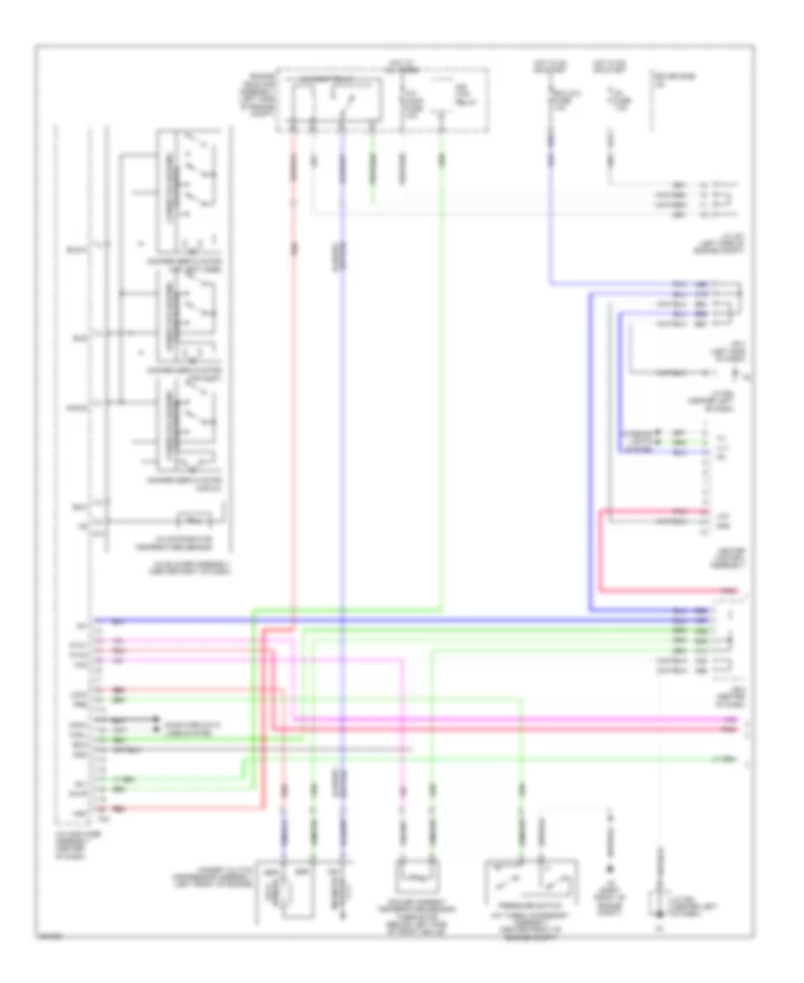
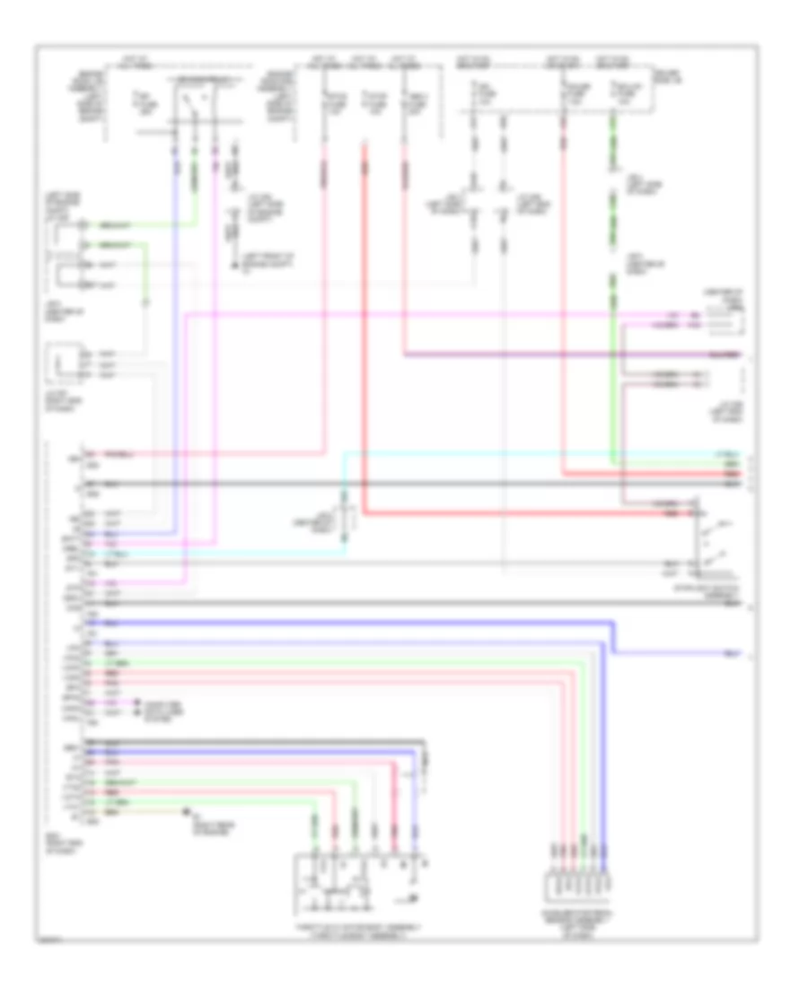
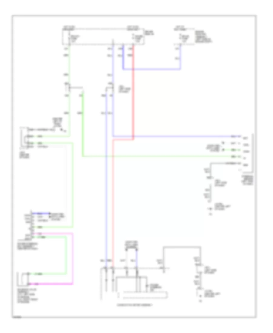
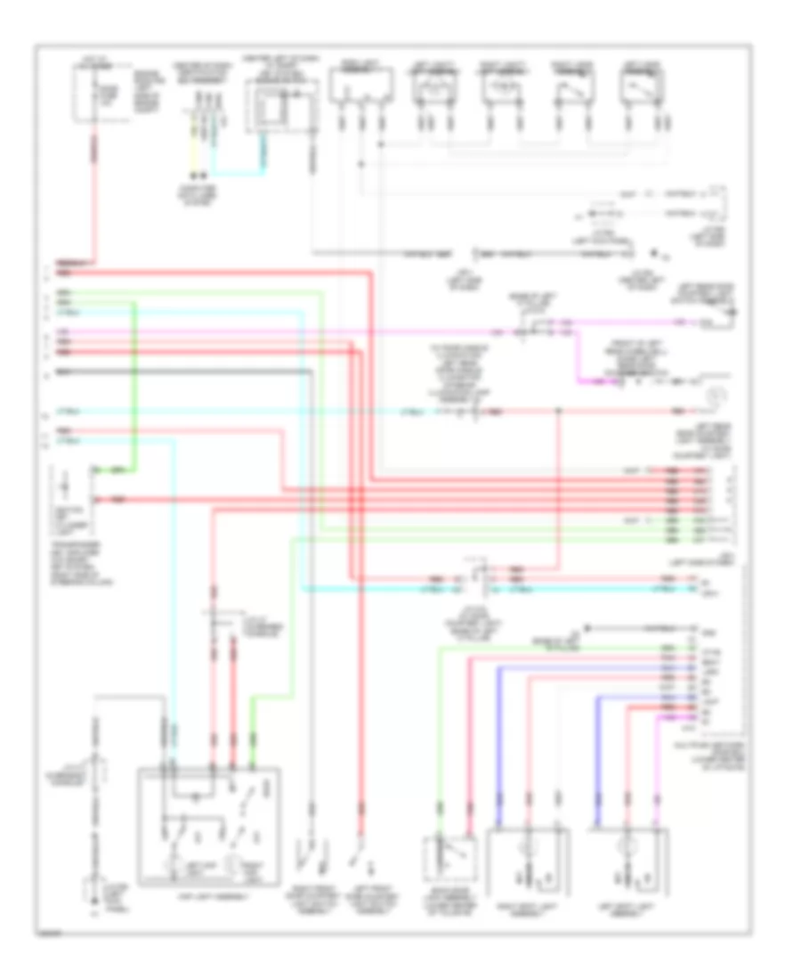
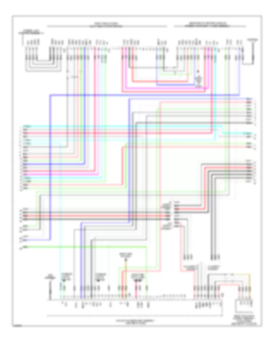
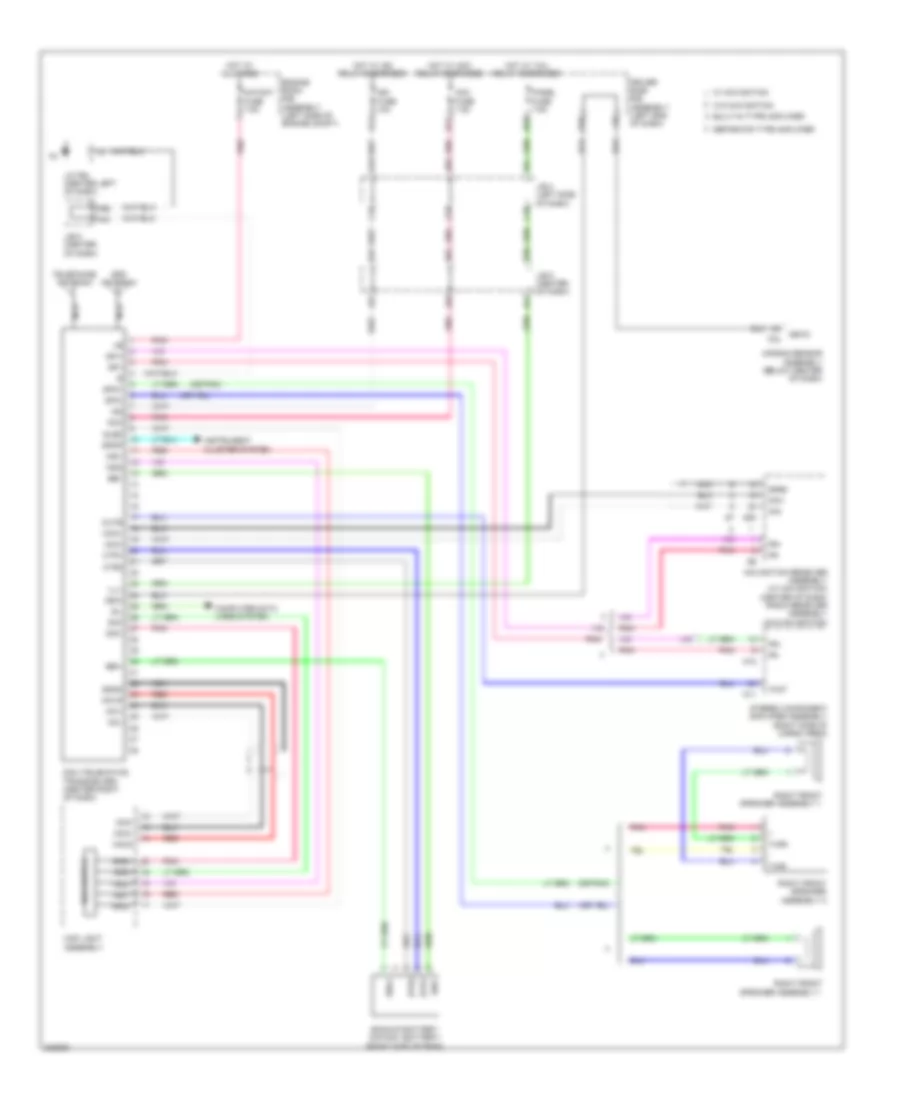
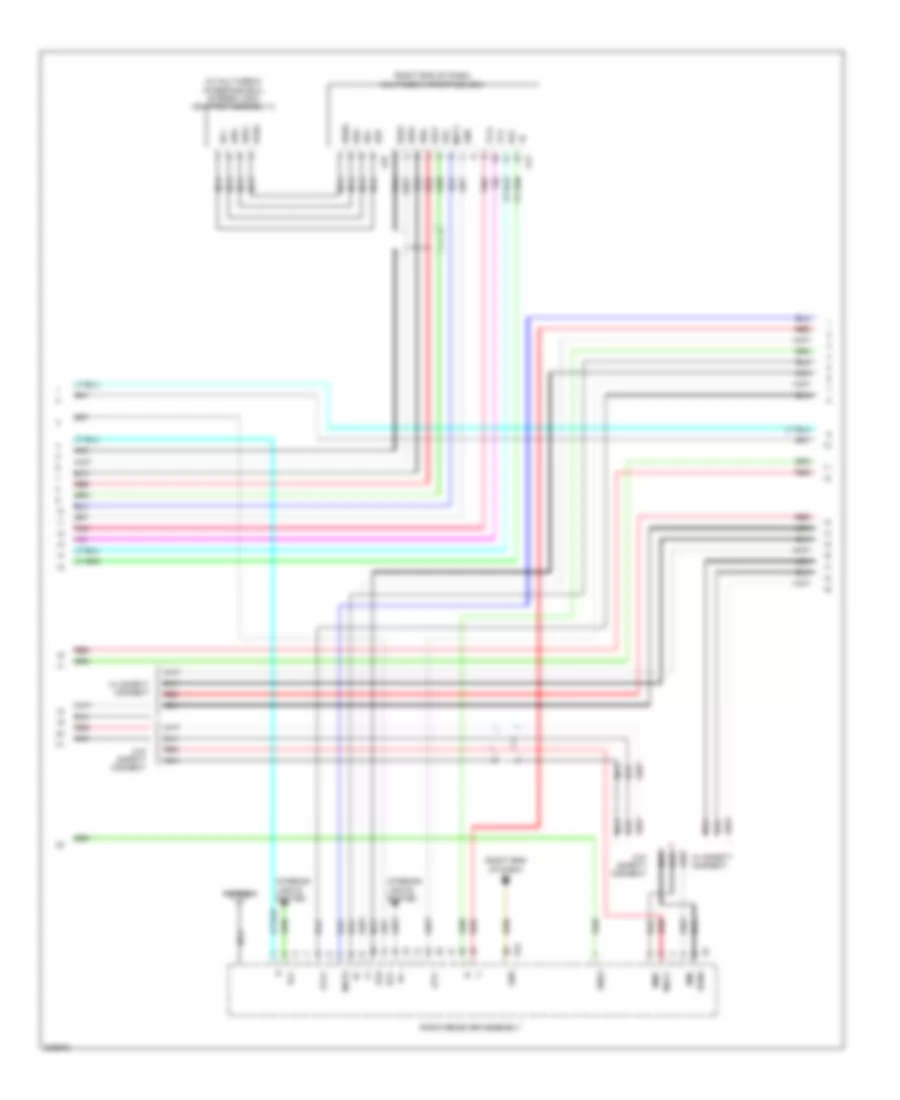
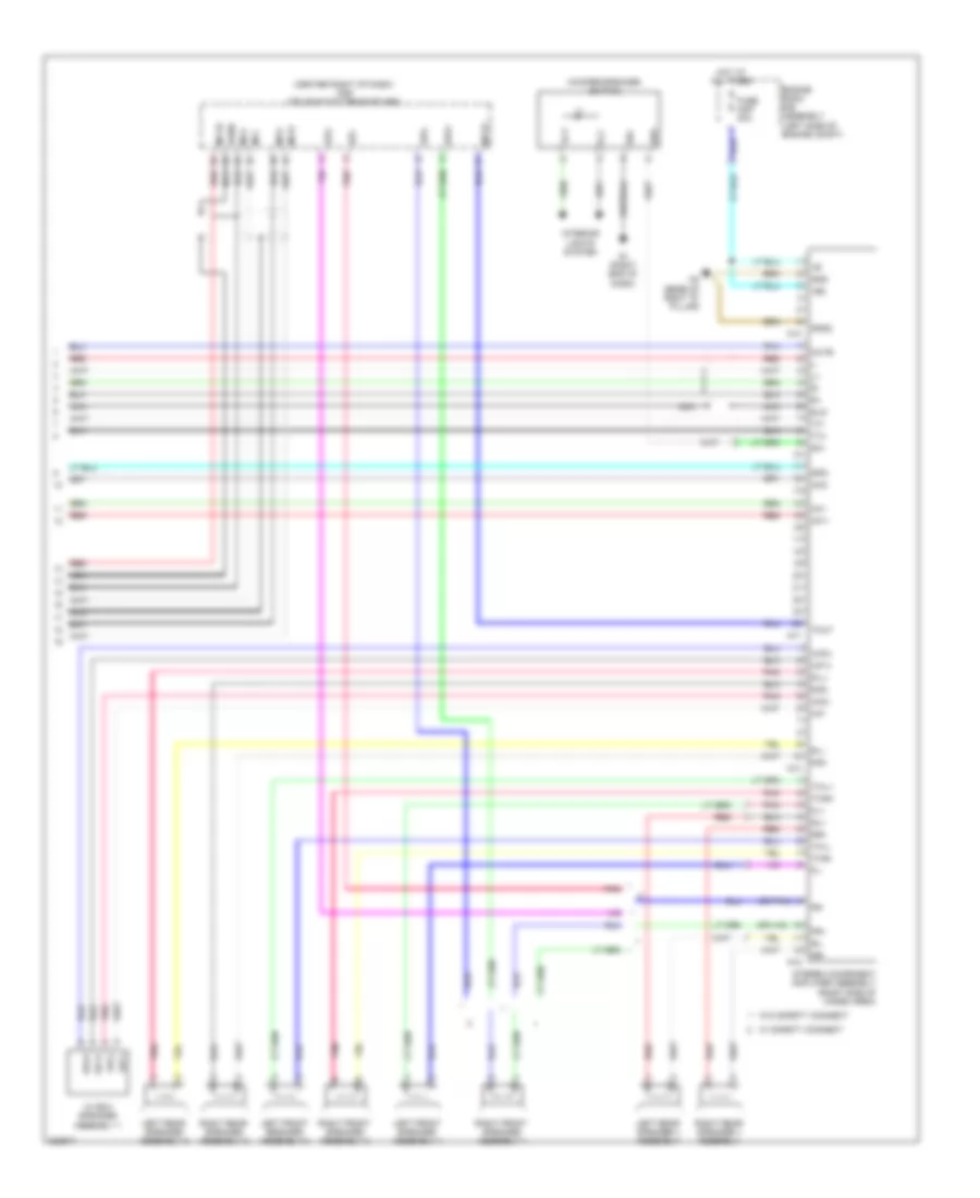
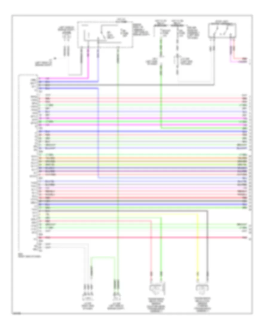
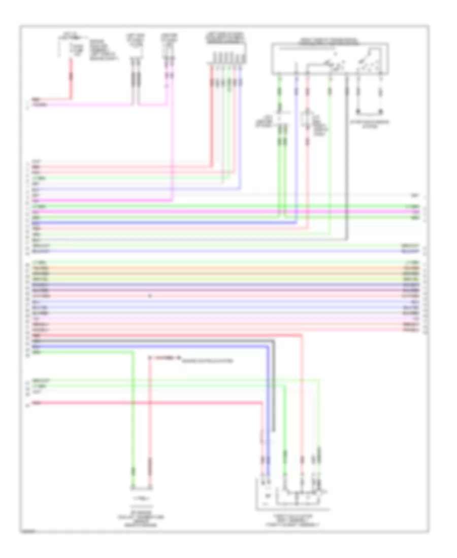
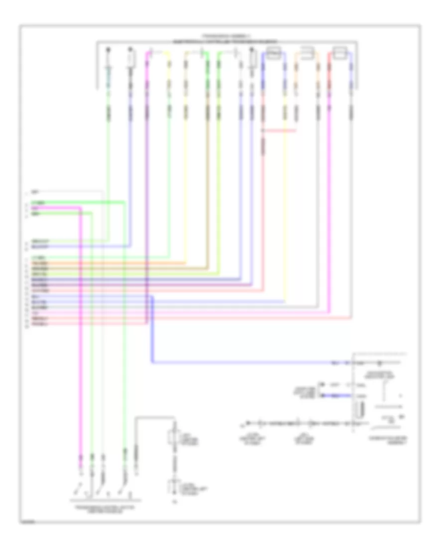
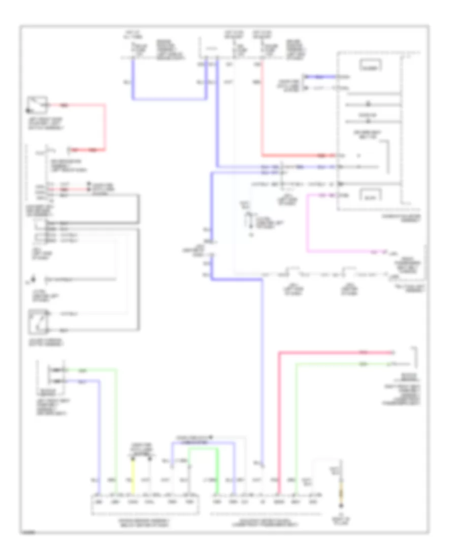
Automatic A/C Wiring Diagram (2 of 2) for Toyota 4Runner Trail 2010
List of elements for Automatic A/C Wiring Diagram (2 of 2) for Toyota 4Runner Trail 2010:
- (center right of dash) blower w/ fan motor sub-assembly
- A/c amplifier assembly (center of dash)
- A/c fuse 7.5a
- A1 (left front of engine compt)
- A24
- A96
- Ac1
- Act
- Alt
- Automatic light control sensor (top center of dash)
- B37
- B38
- Blw
- C38
- Canh
- Canl
- Computer data lines system
- Cooler (room temperature sensor) thermistor (center left of dash)
- Def relay
- Defogger system
- Deicer relay
- Driver side j/b
- Ecm (right end of dash)
- Efi engine coolant temperature sensor (2.7l: top left of engine 4.0l: rear of engine)
- Engine room r/b 3 assembly (left side of engine compt)
- Engine room r/b assembly (left side of engine compt)
- Ethw
- F42
- F50
- F85
- F86
- F87
- Fdef
- Fdfi
- Generator assembly (w/ ptc heater)
- Gnd
- Hot at all times
- Htr fuse 50a
- J/b 5 (center of dash)
- J/c a38 (left side of engine compt)
- J/c f63 (left kick panel)
- J/c f65 (right kick panel)
- Lin1
- Pnk
- Ptc htr 1 fuse 30a
- Ptc htr 2 fuse 30a
- Ptc htr 3 fuse 30a
- Ptc relay 1 (if equipped)
- Ptc relay 2 (if equipped)
- Ptc relay 3 (if equipped)
- Ptc2
- Quick heater assembly (w/ ptc heater) (center left of dash)
- Rdef
- Red
- Sg-1
- Solar sensor
- Sw 1
- Thw
- Tsd
- Tsl
- Tsp
- Tsr
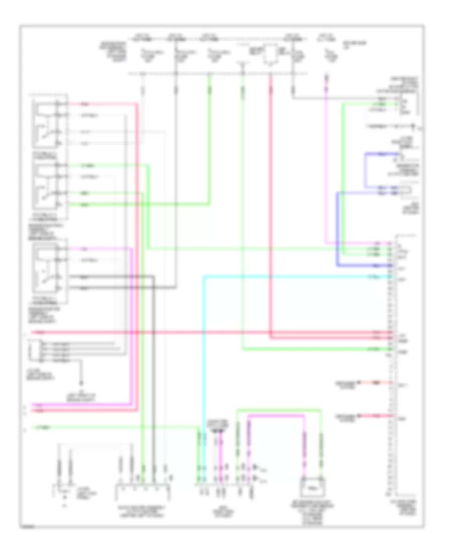
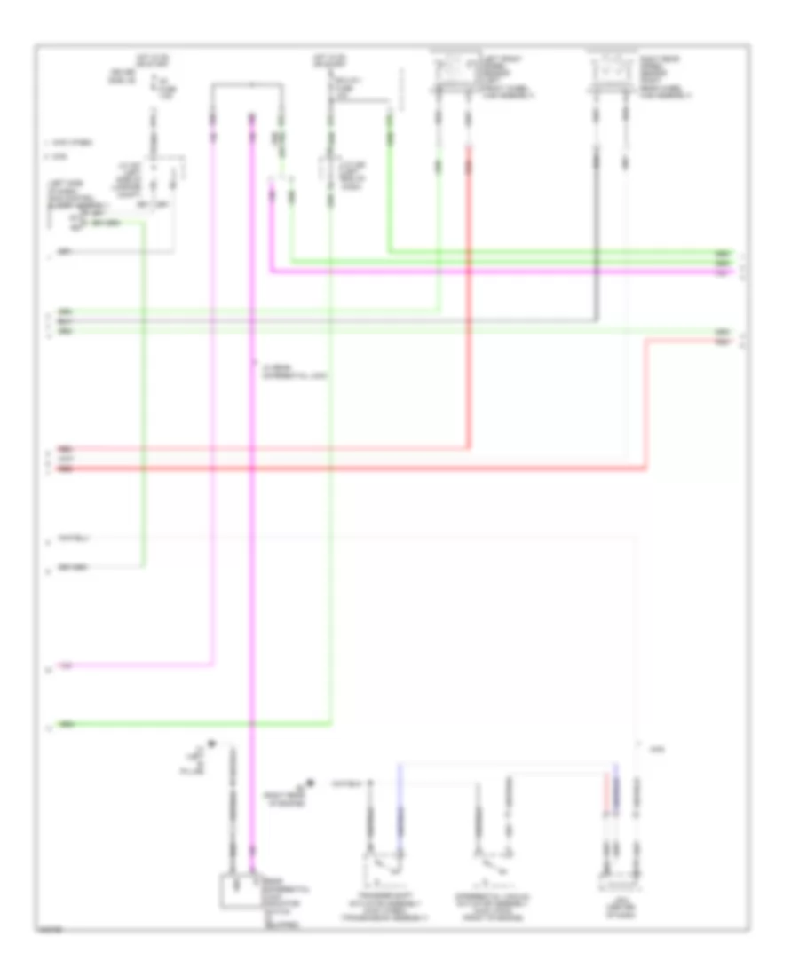
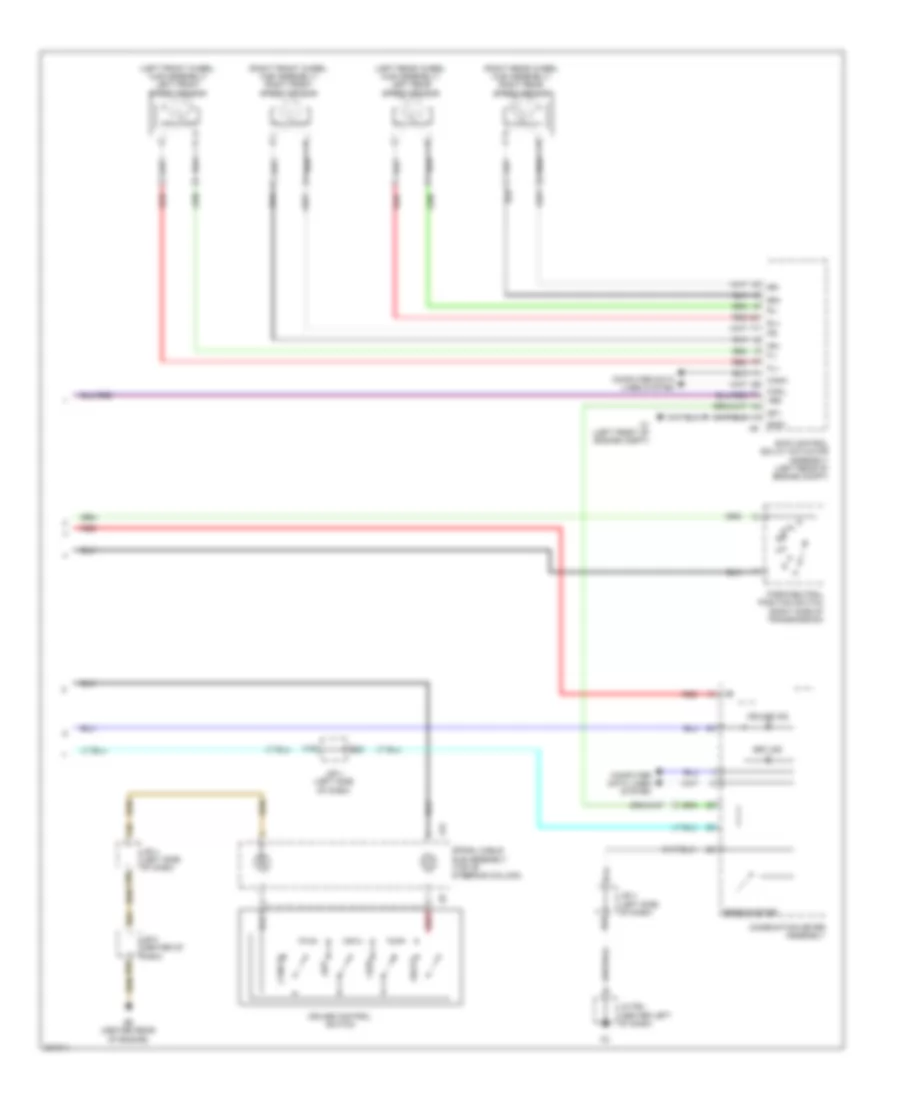
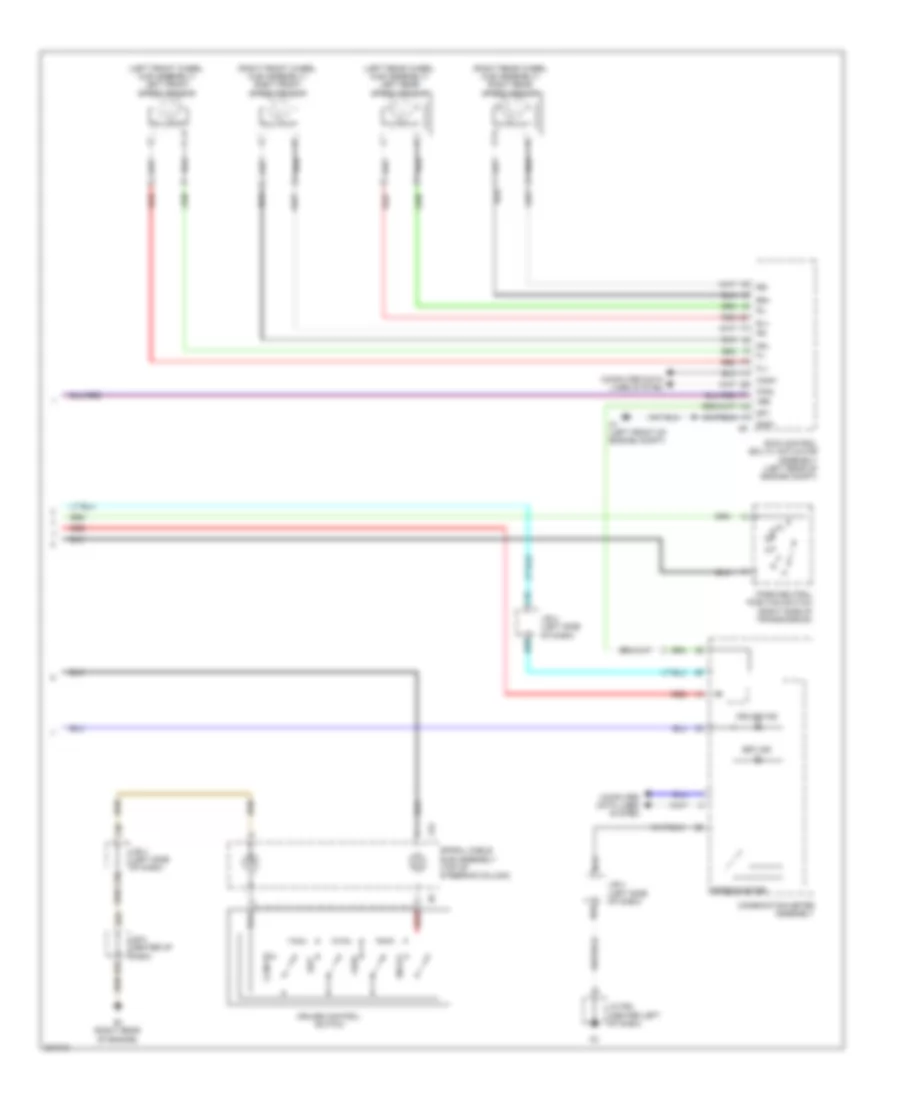
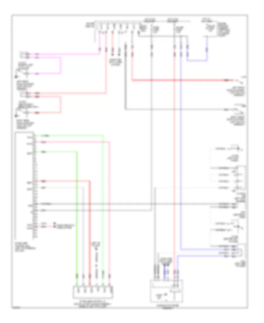
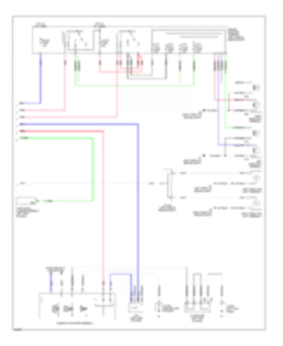
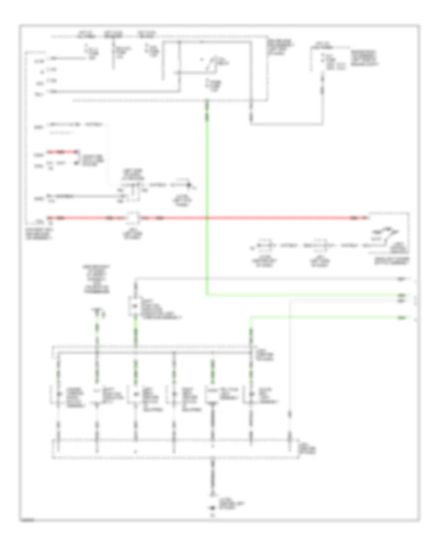
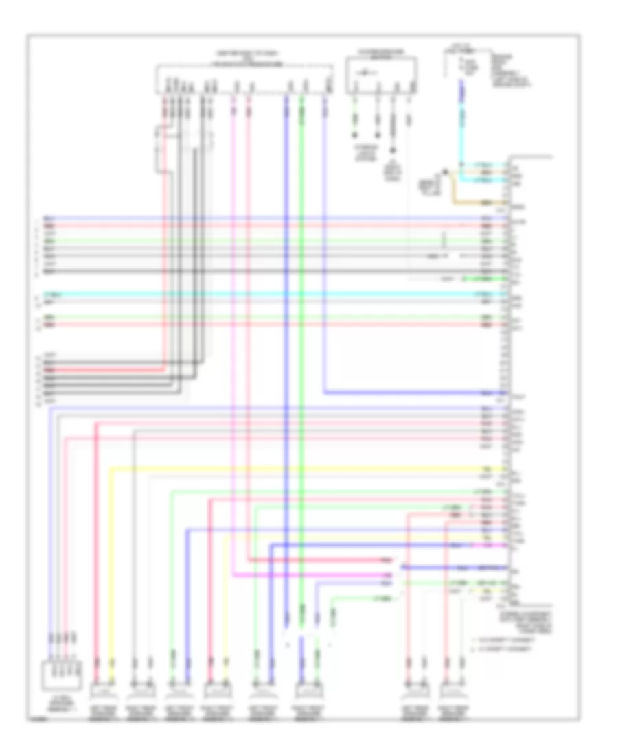
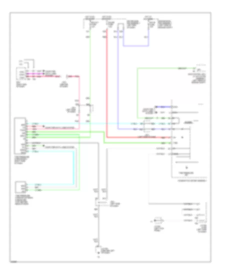
Manual A/C Wiring Diagram (1 of 2) for Toyota 4Runner Trail 2010
List of elements for Manual A/C Wiring Diagram (1 of 2) for Toyota 4Runner Trail 2010:
- A/c amplifier assembly (center of dash)
- A/c blower assembly (center right of dash)
- A/c comp fuse 10a
- A/c comp relay
- A/c evaporator temperature sensor
- A/c tube & accessory assembly (center front of engine compt)
- A14
- A2 (right front of engine compt)
- A26
- A27
- A32
- A66
- Ac1
- B bus
- B26
- B39
- B49
- B50
- B55
- B63
- Bus
- Bus g
- C19
- Canh
- Canl
- Color (green) connector housing
- Computer data lines system
- Connector housing color (black)
- Connector housing color (red)
- Cooler (ambient temperature sensor) thermistor (behind left side of front grille)
- D11
- Damper servo motor (air inlet)
- Damper servo motor (air mix)
- Damper servo motor (air vent mode)
- Driver side j/b
- Ecu-ig 2 fuse 10a
- Engine room r/b assembly (left side of engine compt)
- F42
- Gnd
- Heater control assembly
- Hot at all times
- Hot in on or start
- Ig+
- Ig1 fuse 7.5a
- Ill+
- Ill-
- Interior lights system
- J/b 4 (left side of dash)
- J/b 5 (center of dash)
- J/c a37 (left side of engine compt)
- J/c f64 (center left of dash)
- Lin1
- Lock
- Magnet clutch compressor assembly (left front of engine)
- Magnetic clutch
- Mg+
- Mgc
- Mhtr
- Mir htr relay
- Pnk
- Pre
- Pressure switch
- Ptc1
- Ptc3
- Red
- Sensor lock
- Sg-2
- Sg-3
- Ssr+
- Ssr-
- Tam
- Z14
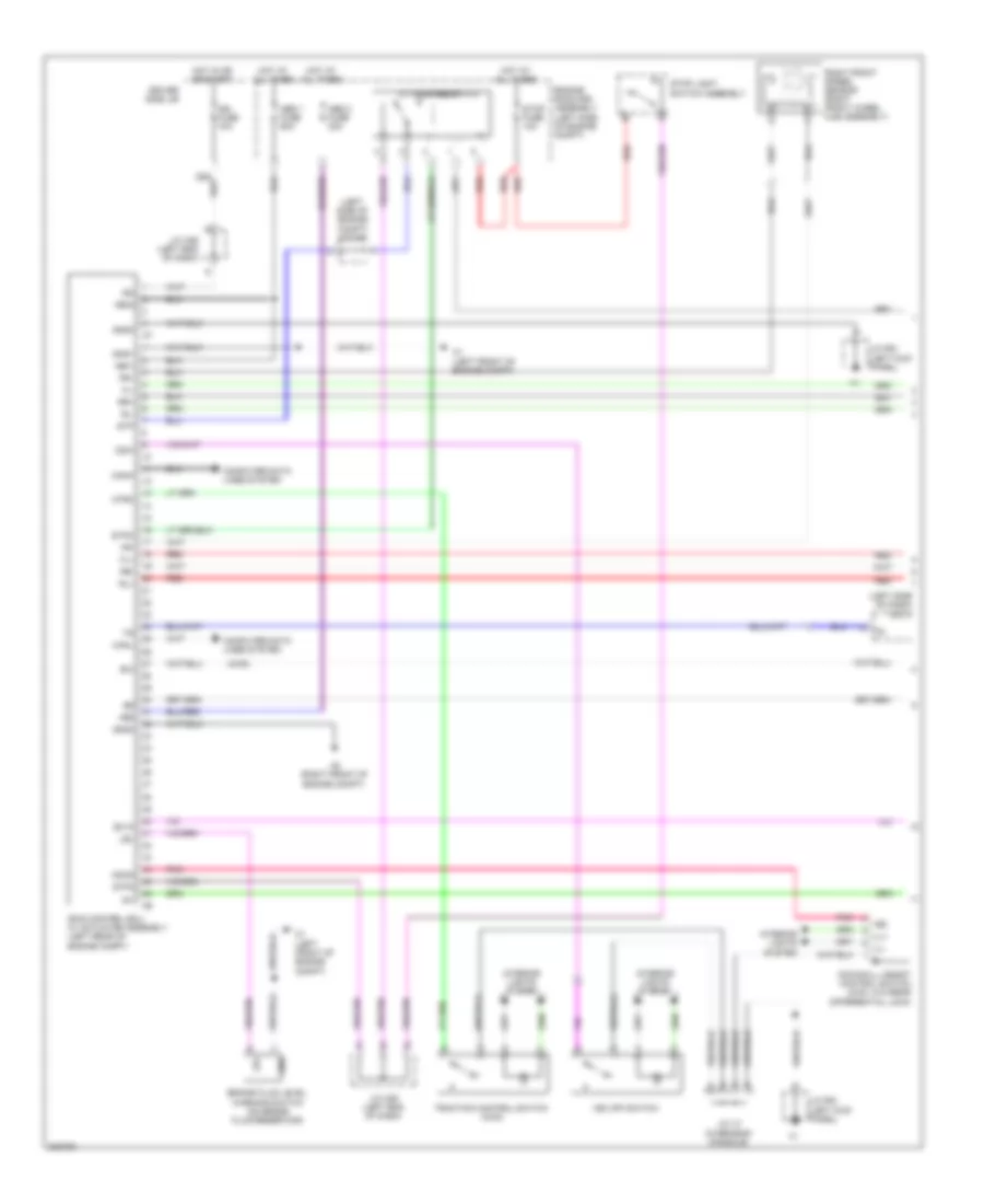
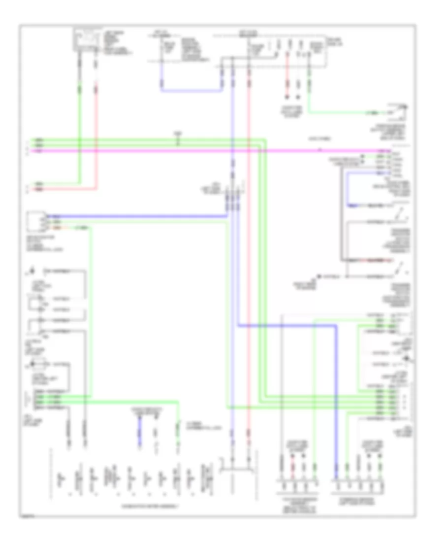
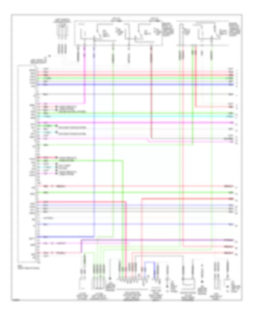
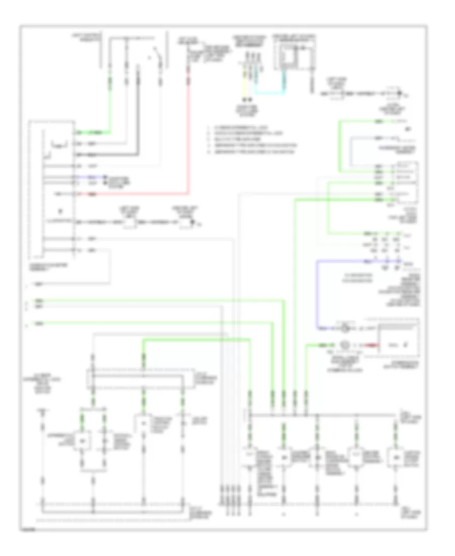
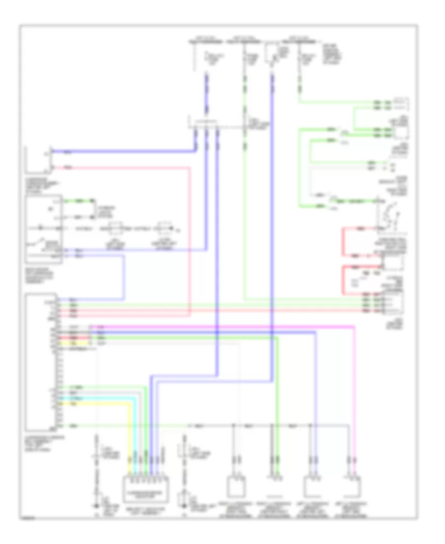
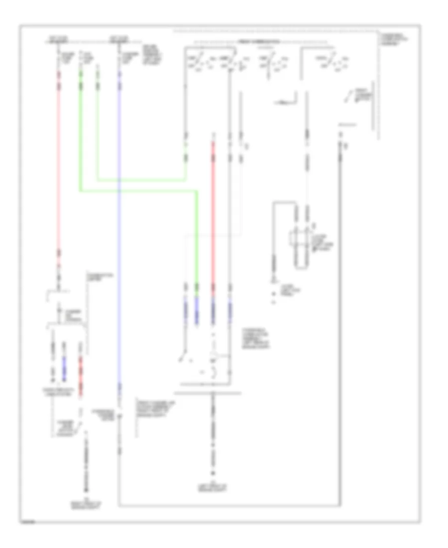
Manual A/C Wiring Diagram (2 of 2) for Toyota 4Runner Trail 2010
List of elements for Manual A/C Wiring Diagram (2 of 2) for Toyota 4Runner Trail 2010:
- (center right of dash) blower w/ fan motor sub-assembly
- 2.7l
- 4.0l
- A/c amplifier assembly (center of dash)
- A/c fuse 7.5a
- A1 (left front of engine compt)
- A24
- A96
- Ac1
- Act
- Alt
- B37
- B38
- Blw
- C38
- Canh
- Canl
- Computer data lines system
- Def relay
- Defogger system
- Deicer relay
- Driver side j/b
- Ecm (right end of dash)
- Efi engine coolant temperature sensor (2.7l: top left of engine) (4.0l: rear of engine)
- Engine room r/b 3 assembly (left side of engine compt)
- Engine room r/b assembly (left side of engine compt)
- Ethw
- F42
- F50
- F85
- F86
- F87
- Fdef
- Fdfi
- Generator assembly (w/ ptc heater)
- Gnd
- Hot at all times
- Htr fuse 50a
- J/b 5 (center of dash)
- J/c a38 (left side of engine compt)
- J/c f63 (left kick panel)
- J/c f65 (right kick panel)
- Lin1
- Pnk
- Ptc htr 1 fuse 30a
- Ptc htr 2 fuse 30a
- Ptc htr 3 fuse 30a
- Ptc relay 1 (if equipped)
- Ptc relay 2 (if equipped)
- Ptc relay 3 (if equipped)
- Ptc2
- Quick heater assembly (w/ ptc heater) (center left of dash)
- Rdef
- Red
- Sw 1
- Thw
ANTI-LOCK BRAKES
Anti-lock Brakes Wiring Diagram (1 of 3) for Toyota 4Runner Trail 2010
List of elements for Anti-lock Brakes Wiring Diagram (1 of 3) for Toyota 4Runner Trail 2010:
- (4wd)
- (left side of dash) dlc 3
- (left side of engine compt) j/c a39
- +b2 ill+ ill- e
- +bm1
- +bm2
- +bs
- A1 (left front of engine compt)
- A2 (right front of engine compt)
- Abs 1 fuse 50a
- Abs 2 fuse 30a
- Atrc
- Brake fluid level warning switch (on brake fluid reservoir)
- Canh
- Canl
- Computer data lines system
- Csw
- Downhill assist control switch (4wd, w/o rear differential lock)
- Driver side j/b
- Engine room r/b assembly (left side of engine compt)
- Ex13
- Exi
- Fl+
- Fl-
- Fr+
- Fr-
- Gnd
- Gnd1
- Gnd2
- Gnd3
- Hdcs
- Hot at all times
- Hot in or or start
- Ig1
- Ig2
- Ign fuse 10a
- Interior lights system
- J/c a36 (left end of dash)
- J/c f63 (left kick panel)
- J/c u7 (overhead console)
- Lbl
- Pnk
- Red
- Right front speed sensor (right front wheel hub assembly)
- Rl+
- Rl-
- Rr+
- Rr-
- Skid control ecu w/ actuator assembly (left rear of engine compt)
- Stop fuse 10a
- Stop light switch assembly
- Stop lp relay
- Stp
- Stp2
- Stpo
- Traction control switch (4wd)
- Vsc off switch
Anti-lock Brakes Wiring Diagram (2 of 3) for Toyota 4Runner Trail 2010
List of elements for Anti-lock Brakes Wiring Diagram (2 of 3) for Toyota 4Runner Trail 2010:
- (left side of dash) skid control buzzer assembly
- 2wd
- 4wd
- 4wd (vf4bm)
- A18
- B2 (right rear of engine)
- B22
- B54
- C31
- D11
- D30
- D31
- Differential vacuum actuator assembly (4wd (vf2a)) (front of engine)
- Driver side j/b
- Ecu-ig 1 fuse 10a
- F20
- Gnd
- Hot in on or start
- Ig1
- Ig1 fuse 7.5a
- J/b 5 (center of dash)
- J/c a36 (left end of dash)
- J/c a37 (left side of luggage compt)
- Left front speed sensor (left front wheel hub assembly)
- O1 (left "b" pillar)
- Rear differential lock indicator switch (if equipped)
- Red
- Right rear speed sensor (right rear wheel hub assembly)
- Transfer shift actuator assembly (4wd (vf4bm)) (transmission assembly)
- W/ rear differential lock
Anti-lock Brakes Wiring Diagram (3 of 3) for Toyota 4Runner Trail 2010
List of elements for Anti-lock Brakes Wiring Diagram (3 of 3) for Toyota 4Runner Trail 2010:
- +b ig
- 2wd
- 4wd (vf4bm)
- A-trac ind
- A52
- A64
- A65
- A68
- A76
- A80
- A82
- Abs ind
- Auto lsd ind
- B14
- B2 (right rear of engine)
- B22
- B23
- B35
- B63
- Bat
- Becu
- Brake ind
- C20
- C55
- Canh
- Canl
- Combination meter assembly
- Computer data lines system
- Control ind assist
- Crawl ind
- D17
- D39
- Down hill
- Drive monitor switch (w/ rear differential lock)
- Driver side j/b
- Ecu-b fuse 10a
- Engine room r/b assembly (left side of engine compartment)
- Ess
- F55
- F56
- Four wheel drive control ecu (right side of dash)
- Gauge fuse 7.5a
- Gnd
- Hot at all times
- Hot in on or start
- Ig1
- J/b 4 (left side of dash)
- J/b 5 (center of dash)
- J/c f55 & f56 (left side of dash)
- J/c f63 (left kick panel)
- J/c f64 (center left of dash)
- Left rear speed sensor (left rear wheel hub assembly)
- Lin
- Main body ecu
- Multi terrain
- Parking brake switch assembly (upper left end of dash)
- Pkb
- Red
- Rlp canh canl 4wd 4wdl f47
- Select ind
- Slip ind
- Steering sensor (left side of dash)
- Trac off ind
- Transfer indicator switch (4wd position) (transmission assembly)
- Transfer indicator switch (l4 position) (transmission assembly)
- Vsc off
- W/ rear differential lock
- Yaw rate sensor assembly (below front of center console)
ANTI-THEFT
Forced Entry Wiring Diagram, with Smart Key System (1 of 5) for Toyota 4Runner Trail 2010
List of elements for Forced Entry Wiring Diagram, with Smart Key System (1 of 5) for Toyota 4Runner Trail 2010:
- (base of left "d" pillar) o2
- A19
- A20
- A21
- A24
- A60
- Acc
- Acc fuse 7.5a
- Act+
- Act-
- Actd
- Altb
- B11
- B14
- B15
- B18
- B29
- B34
- Back door lock assembly (lower center of tailgate)
- Becu
- Bk dr lock relay
- Canh
- Canl
- Computer data lines system
- Courtesy
- D-dr unlock relay
- D/l 2 fuse 25a
- D23
- D24
- D25
- D29
- D39
- D40
- Dash)
- Dim
- Door lock control switch
- Door lock relay
- Dr unlock relay
- Driver side r/b assembly (left end of dash)
- Ecu-ig 2 fuse 10a
- Exterior lights system
- F10
- F19
- F24
- F25
- F27
- F55
- F56
- F58
- Flcy
- Frcy
- Gnd1
- Gnd2
- H1 (rear of right front door)
- Haz
- Hcty
- Headlights system
- Horn
- Hot at all times
- Hot in on or acc
- Hot in on or start
- Hrly
- Ile
- Ind
- Interior lights system
- J/b 4 (left side of dash)
- J/c f55 & f56 (left side of f55
- J/c f55 & f56 (left side of f56
- J/c f57 & f58 (right end of f57
- J/c f63 (left kick panel)
- J/c h8 (front of right front door)
- J/c n22 (above right rear wheelwell)
- J/c o18 (base of left "c" pillar)
- Lcty
- Left front door courtesy light switch assembly
- Left rear door courtesy light switch assembly
- Lin1
- Lin2
- Lock
- Lsfl
- Lsfr
- Lswl
- Lswr
- Main body ecu (driver side j/b assembly)
- Multiplex network master switch assembly (left front door)
- Pnk
- Rcty
- Red
- Right door control switch assembly
- Right front door courtesy light switch assembly
- Right rear door courtesy light switch assembly
- Tr+
- Trly
- Ul1
- Ul3
- Unlock
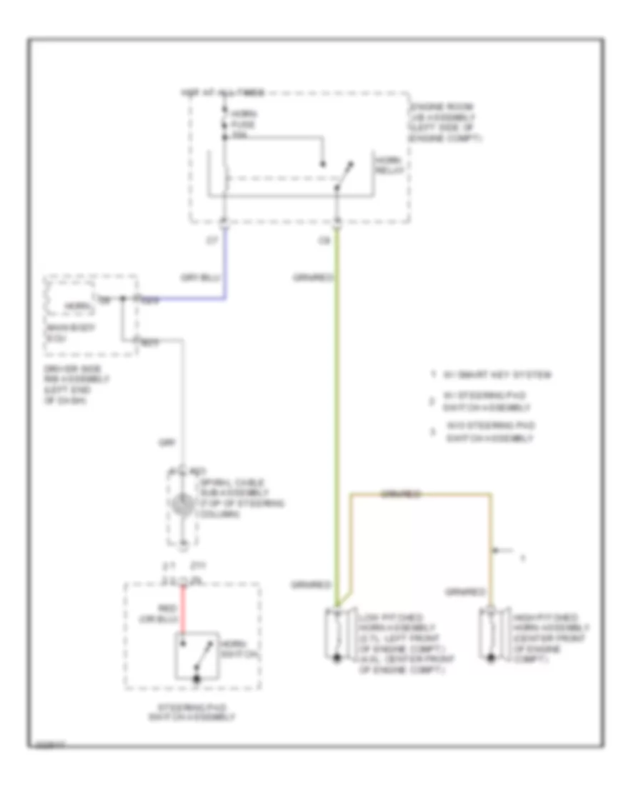
Forced Entry Wiring Diagram, with Smart Key System (2 of 5) for Toyota 4Runner Trail 2010
List of elements for Forced Entry Wiring Diagram, with Smart Key System (2 of 5) for Toyota 4Runner Trail 2010:
- (2.7l: left front of engine compt) (4.0l: center front of engine compt) low pitched horn assembly
- (left "b" pillar) o1
- (lower center of liftgate) multiplex network door ecu
- (rear of left front door)
- (rear of right front door)
- (right "b" pillar) n1
- Back door opener switch
- Bdcy
- Bdr
- Becu
- C31
- Ctye
- D33
- Dome fuse 10a
- Door back fuse 30a
- Driver side r/b assembly (left end of dash)
- Ecu-b fuse 10a
- Ecu-ig fuse 10a
- Engine room j/b assembly (left side of engine compt)
- Engine room r/b assembly (left side of engine compt)
- F11
- F30
- F32
- F57
- F58
- Gnd
- High pitched horn assembly (center front of engine compt)
- Horn fuse 10a
- Horn relay
- Hot at all times
- Hot in on or start
- Hsw+
- Hsw-
- Hswz
- Interior lights system
- J/c f57 & f58 (right end of dash)
- J/c h8 (front of right front door)
- J/c i8 (front of left front door)
- J/c o18 (base of left "c" pillar)
- Left front door w/ motor lock assembly (left front door)
- Left rear door w/
- License plate light assembly
- Lock
- Lock key
- Motor lock assembly (left rear door)
- Motor lock assembly (right rear door)
- Mpx1
- O2 (base of left "d" pillar)
- Pnk
- Red
- Right front door w/ motor lock assembly (right front door)
- Right rear door w/
- Sig
- Sup2
- Tion detec- unlock
- Un- key
- W10
Forced Entry Wiring Diagram, with Smart Key System (3 of 5) for Toyota 4Runner Trail 2010
List of elements for Forced Entry Wiring Diagram, with Smart Key System (3 of 5) for Toyota 4Runner Trail 2010:
- (center left of dash) engine switch
- (left rear of engine compt)
- (right end of dash)
- A12
- A16
- A59
- A64
- A66
- Accd
- Am21
- Am22
- Antenna coil
- Assembly
- B20
- B25
- B35
- B36
- B37
- B59
- B62
- B63
- B69
- C16
- C20
- C56
- Ca1h
- Ca1l
- Ca3n
- Ca3p
- Canh
- Canl
- Computer data lines system
- Ecm
- Engine room r/b assembly (left side of engine compt)
- F50
- F80
- F81
- Gnd
- Gnd2
- Hot at all times
- Ig1d
- Ig2d
- Imi
- Imo
- Inds
- Indw
- J/b 4 (left side of dash)
- J/b 5 (center of dash)
- J/c a36 (left end of dash)
- J/c f64 (center left of dash)
- Lin2
- Neo
- Park/neutral position switch (right side of transmission)
- Pnk
- Power distribution system
- Power management control ecu (center of dash)
- Red
- Shift interlock system
- Shift lock control ecu sub-assembly (under center console)
- Skid control ecu w/ actuator
- Slp
- Slr+
- Sp1
- Spd
- Ss1
- Ss2
- Ssw1
- Ssw2
- Sta
- Star
- Starting/ charging system
- Stop fuse 10a
- Stop light switch assembly
- Stp1
Forced Entry Wiring Diagram, with Smart Key System (4 of 5) for Toyota 4Runner Trail 2010
List of elements for Forced Entry Wiring Diagram, with Smart Key System (4 of 5) for Toyota 4Runner Trail 2010:
- (center left of dash) id code box
- (center of dash) j/b 5
- (left front of engine compt) a1
- (left side of dash) j/b 4
- A48
- A49
- A53
- A57
- A68
- B14
- B22
- B27
- B30
- B63
- B68
- B71
- Buzzer
- C17
- C45
- C51
- C55
- C57
- C60
- Combination meter assembly
- Computer data lines system
- Door ind
- Driver side r/b assembly (left end of dash)
- Efii
- Efio
- Engine hood courtesy switch (center front of engine compt)
- Engine room r/b assembly (left side of engine compt)
- Gauge fuse 7.5a
- Gnd
- Hot at all times
- Hot in on or start
- Ign fuse 10a
- Ind
- J/b 4 (left side of dash)
- J/c f64 (center left of dash)
- Lin1
- Pnk
- Red
- S-horn relay
- Security fuse 10a
- Security horn assembly (right front of engine compt)
- Smart fuse 7.5a
- Smart key
Forced Entry Wiring Diagram, with Smart Key System (5 of 5) for Toyota 4Runner Trail 2010
List of elements for Forced Entry Wiring Diagram, with Smart Key System (5 of 5) for Toyota 4Runner Trail 2010:
- (base of left "c" pillar)
- (center console) front indoor electrical key antenna assembly
- (center of dash) j/b 5
- (center of luggage compt)
- A50
- A51
- A52
- A55
- A60
- A62
- A63
- A64
- A66
- A69
- Agnd
- Ant1
- Ant2
- B35
- B59
- Canh
- Canl
- Certification ecu assembly (center side of dash)
- Cg1b
- Cg2b
- Cg5b
- Cg6b
- Cg7b
- Cg8b
- Clg1
- Clg2
- Clg5
- Clg6
- Clg7
- Clg8
- Clgb
- Code
- Computer data lines system
- Cutb
- Data
- Door control receiver (rear of left "c" pillar)
- F78
- F79
- Gnd
- Ind
- Indoor luggage compartment electrical key antenna assembly
- J/b 4 (left side of dash)
- J/c f64 (center left of dash)
- Left front outside electrical key antenna
- Lin
- O2 (base of left "d" pillar)
- Outside luggage electrical key antenna (center rear of luggage compt)
- Pnk
- Pos1
- Pos2
- Rco
- Rda
- Rear indoor electrical key antenna assembly
- Red
- Right front outside electrical key antenna (top rear of right front door)
- Rssi
- Security indicator light assembly
- Sen1
- Sen2
- Sens
- Swil
- Trg+
- Tsw1
- Tsw2
- Tsw5
- Tsw6
- Txct
- Vc5
Forced Entry Wiring Diagram, without Smart Key System (1 of 3) for Toyota 4Runner Trail 2010
List of elements for Forced Entry Wiring Diagram, without Smart Key System (1 of 3) for Toyota 4Runner Trail 2010:
- (base of left "d" pillar) o2
- A19
- A20
- A21
- A24
- A60
- Acc
- Acc fuse 7.5a
- Act+
- Act-
- Actd
- Altb
- B11
- B15
- B17
- B18
- B33
- B34
- Back door lock assembly (lower center of tailgate)
- Becu
- Bk dr lock relay
- Bzr
- Canh
- Canl
- Computer data lines system
- Courtesy
- D-dr unlock relay
- D/l 2 fuse 25a
- D13
- D23
- D24
- D25
- D29
- D39
- D40
- Dash)
- Dim
- Door lock control switch
- Door lock relay
- Dr unlock relay
- Driver side r/b assembly (left end of dash)
- Ecu-ig 2 fuse 10a
- Exterior lights system
- F10
- F19
- F24
- F25
- F27
- F55
- F56
- F58
- Flcy
- Frcy
- Gnd1
- Gnd2
- H1 (rear of right front door)
- Haz
- Hcty
- Headlights system
- Horn
- Hot at all times
- Hot in on or acc
- Hot in on or start
- Hrly
- Ile
- Ind
- Interior lights system
- J/b 4 (left side of dash)
- J/c f55 & f56 (left side of f55
- J/c f55 & f56 (left side of f56
- J/c f57 & f58 (right end of f57
- J/c f63 (left kick panel)
- J/c h8 (front of right front door)
- J/c n22 (above right rear wheelwell)
- J/c o18 (base of left "c" pillar)
- Ksw
- Lcty
- Left front door courtesy light switch assembly
- Left rear door courtesy light switch assembly
- Lin1
- Lin2
- Lock
- Lsfl
- Lsfr
- Lswl
- Lswr
- Main body ecu (driver side j/b assembly)
- Multiplex network master switch assembly (left front door)
- Pnk
- Prg
- Rcty
- Rda
- Red
- Right door control switch assembly
- Right front door courtesy light switch assembly
- Right rear door courtesy light switch assembly
- Tr+
- Trly
- Ul1
- Ul3
- Unlock
Forced Entry Wiring Diagram, without Smart Key System (2 of 3) for Toyota 4Runner Trail 2010
List of elements for Forced Entry Wiring Diagram, without Smart Key System (2 of 3) for Toyota 4Runner Trail 2010:
- (front of right front door) j/c h8
- (left "b" pillar) o1
- (lower center of liftgate) multiplex network door ecu
- (rear of left front door)
- (rear of right front door)
- (right "b" pillar) n1
- Back door opener switch
- Bdcy
- Bdr
- Becu
- Bkl
- Bkul
- C31
- Ctye
- D33
- Dome fuse 10a
- Door back fuse 30a
- Driver side r/b assembly (left end of dash)
- Ecu-b fuse 10a
- Ecu-ig fuse 10a
- Engine room j/b assembly (left side of engine compt)
- Engine room r/b assembly (left side of engine compt)
- F11
- F30
- F32
- F57
- F58
- Gnd
- Horn fuse 10a
- Horn relay
- Hot at all times
- Hot in on or start
- Hsw+
- Hsw-
- Interior lights system
- J/c f57 & f58 (right end of dash)
- J/c i8 (front of left front door)
- J/c o18 (base of left "c" pillar)
- Keye
- Left front door w/ motor lock assembly (left front door)
- Left rear door w/
- License plate light assembly
- Lock
- Lock key
- Low pitched horn assembly (2.7l: left front of engine compt) (4.0l: center front of engine compt)
- Motor lock assembly (left rear door)
- Motor lock assembly (right rear door)
- Mpx1
- O2 (base of left "d" pillar)
- Pnk
- Red
- Right front door w/ motor lock assembly (right front door)
- Right rear door w/
- Sig
- Tion detec- unlock
- Un- key
- W10
Forced Entry Wiring Diagram, without Smart Key System (3 of 3) for Toyota 4Runner Trail 2010
List of elements for Forced Entry Wiring Diagram, without Smart Key System (3 of 3) for Toyota 4Runner Trail 2010:
- (left front of engine compt) a1
- (left rear of engine compt) wireless door lock buzzer
- (rear of left "c" pillar) door control receiver
- (right end of dash) ecm
- 2.7l
- 4.0l
- A1 (left front of engine compt)
- A50
- A64
- A74
- Acc
- B14
- B35
- B36
- B38
- B56
- B59
- B63
- B67
- Buzzer
- C20
- C28
- C29
- C33
- C53
- C55
- Canh
- Canl
- Combination meter assembly
- Computer data lines system
- Diode (backup light) (right end of dash)
- Door ind
- Engine hood courtesy switch (center front of engine compt)
- Engine room r/b assembly (left side of engine compt)
- F50
- Gauge fuse 7.5a
- Gnd
- Hot at all times
- Hot in on or start
- Ig1
- J/b 4 (left side of dash)
- J/b 5 (center of dash)
- J/c b67 (right side of dash)
- J/c f64 (center left of dash)
- Light ind cylinder ignition key
- Lock
- O2 (base of left "d" pillar)
- Park/neutral position switch (right side of transmission)
- Pnk
- Prg
- Rda
- Red
- Room light assembly 1
- S-horn relay
- Security fuse 10a
- Security horn assembly (right front of engine compt)
- Security indicator light assembly
- Tail gate control switch assembly
- Transponder key amplifier (right side of steering column)
- Unlock
- Unlock warning switch assembly
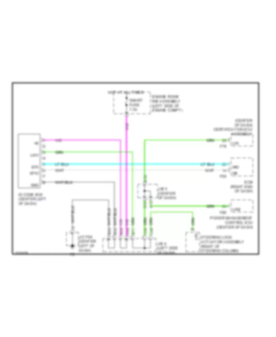
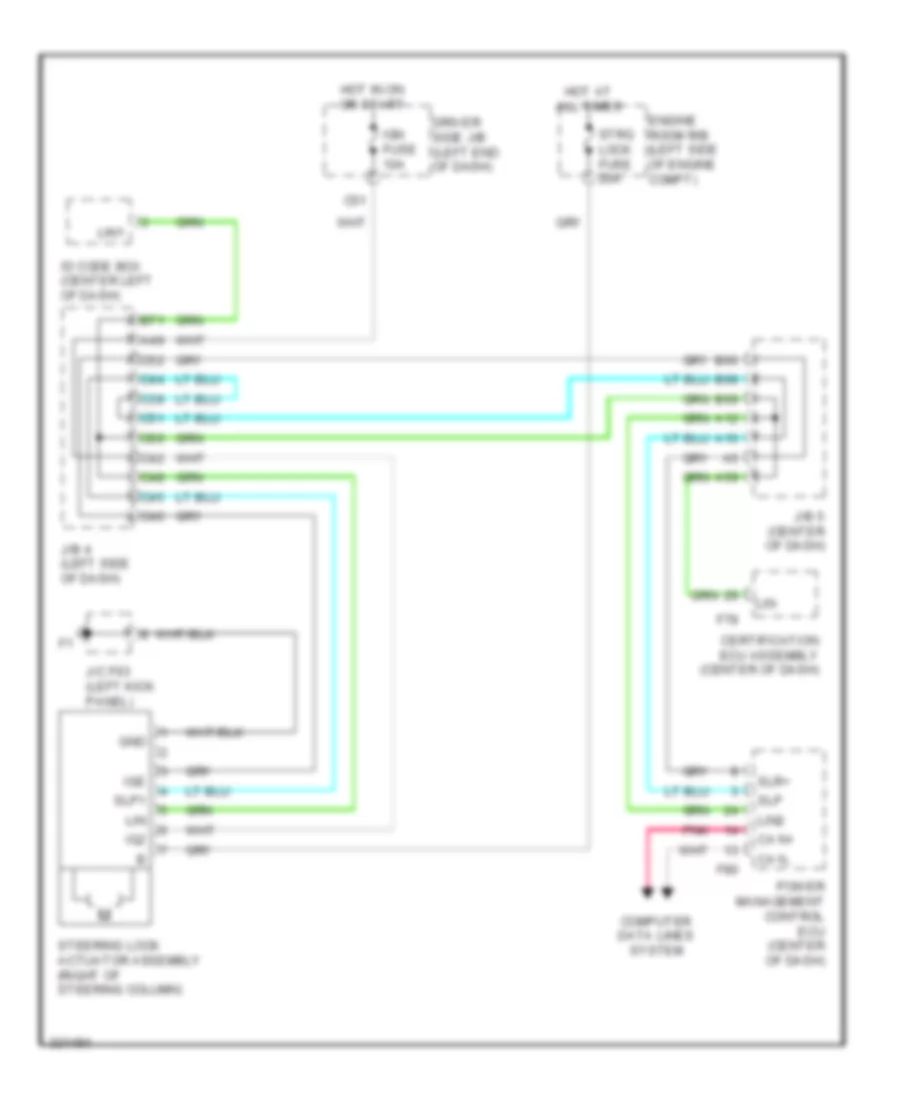
Immobilizer Wiring Diagram, with Smart Key System for Toyota 4Runner Trail 2010
List of elements for Immobilizer Wiring Diagram, with Smart Key System for Toyota 4Runner Trail 2010:
- (center of dash) certification ecu assembly
- A12
- A48
- A59
- B62
- B63
- B68
- B69
- B71
- C48
- C60
- Ecm (right end of dash)
- Efii
- Efio
- Engine room r/b assembly (left side of engine compt)
- F50
- F79
- F80
- Gnd
- Hot at all times
- Id code box (center left of dash)
- Imi
- Imo
- J/b 4 (left side of dash)
- J/b 5 (center of dash)
- J/c f64 (center left of dash)
- Lin
- Lin1
- Lin2
- Power management control ecu (center of dash)
- Smart fuse 7.5a
- Steering lock actuator assembly (right of steering column)
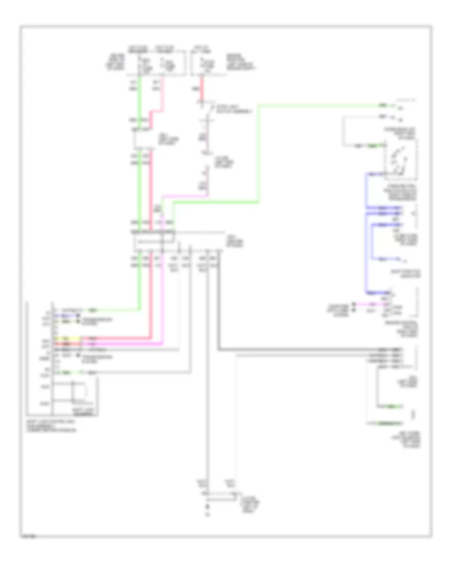
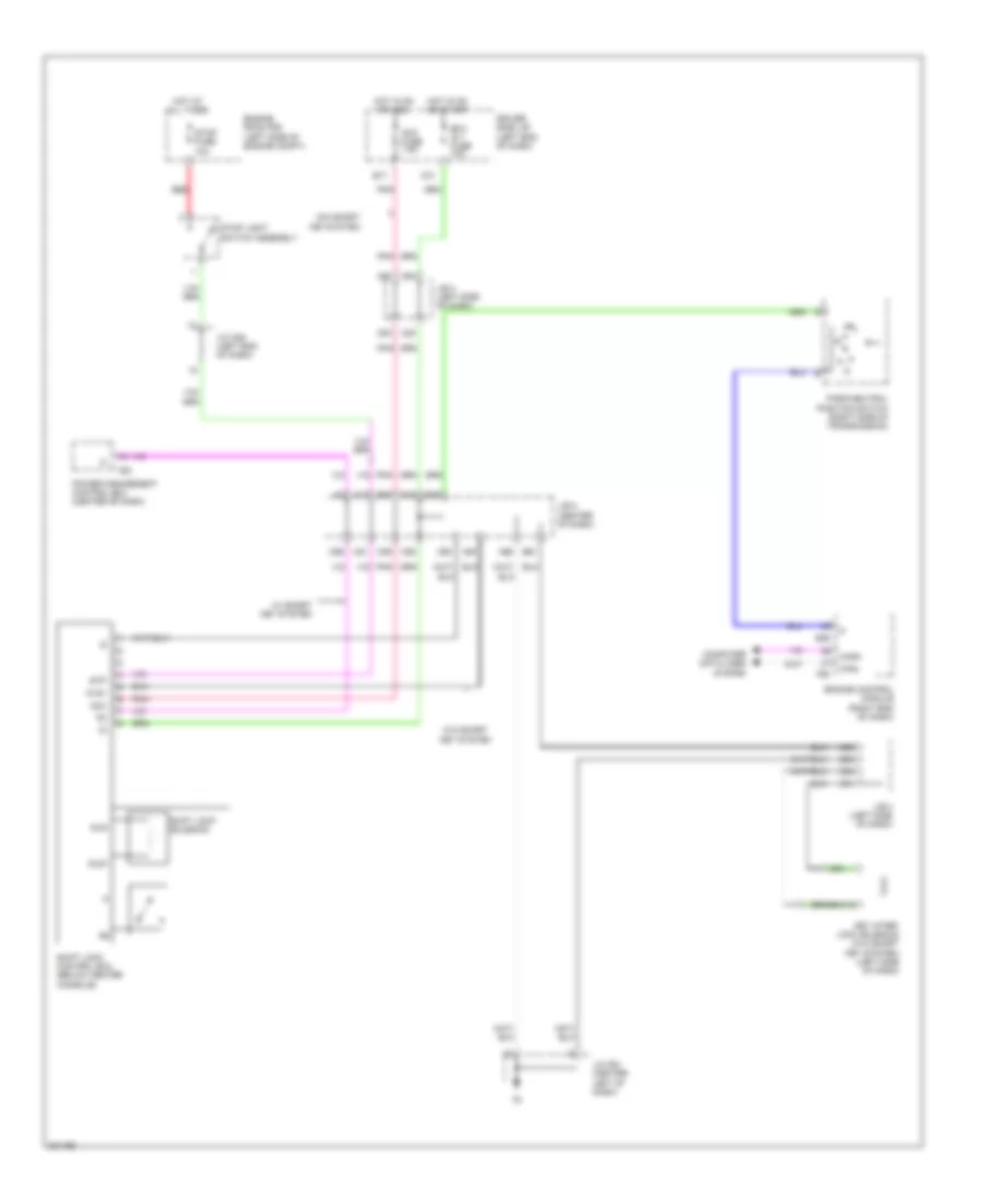
Immobilizer Wiring Diagram, without Smart Key System for Toyota 4Runner Trail 2010
List of elements for Immobilizer Wiring Diagram, without Smart Key System for Toyota 4Runner Trail 2010:
- 2.7l
- 4.0l
- A37
- A49
- Agnd
- Ant1
- Ant2
- B19
- B31
- B34
- B35
- B59
- B61
- B62
- B63
- B65
- B66
- C28
- C33
- C51
- Code
- Computer data lines system
- Cty
- Driver side r/b assembly (left end of dash)
- Ecm (right end of dash)
- Efii
- Efio
- Engine room r/b assembly (left side of engine compt)
- F27
- F50
- Gnd
- Hot at all times
- Hot in on or start
- Ign fuse 10a
- Ignition key cylinder light ind
- Ill+
- Ill-
- Imi
- Imo
- Ind
- Interior lights system
- J/b 4 (left side of dash)
- J/c f64 (center left of dash)
- Ksw
- Left front door courtesy light switch assembly
- Pnk
- Red
- Security fuse 10a
- Security indicator light assembly
- Transponder key amplifier (right side of steering column)
- Transponder key coil
- Transponder key ecu assembly (center left of dash)
- Txct
- Unlock warning switch
- Vc5
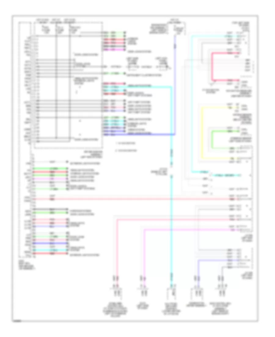
BODY CONTROL MODULES
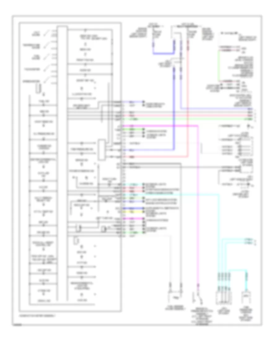
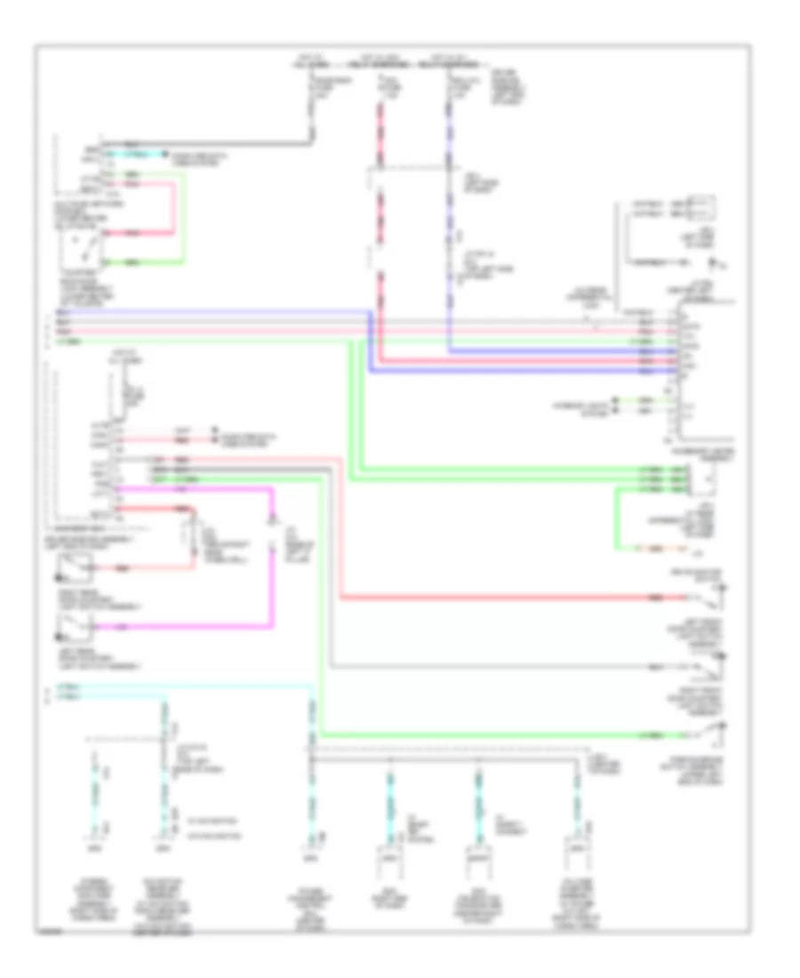
Body Control Modules Wiring Diagram (1 of 2) for Toyota 4Runner Trail 2010
List of elements for Body Control Modules Wiring Diagram (1 of 2) for Toyota 4Runner Trail 2010:
- (left kick panel) j/c f63
- (left side of dash) j/c f55
- (top left side of dash) j/c g13 & g14
- Acc
- Acc fuse 7.5a
- Act+
- Act-
- Actd
- Air bag sensor assembly (below center of dash)
- Altb
- Anti-theft system
- B11
- B15
- B18
- B26
- B33
- B34
- B36
- Becu
- Bzr
- C37
- Canh
- Canl
- Cltb
- Clte
- Clts
- Combination meter assembly
- D/l 2 fuse 25a
- D13
- D17
- D23
- D24
- D25
- D29
- D39
- D40
- Dim
- Dlc3 (left side of dash)
- Door locks & anti-theft systems
- Door locks system
- Driver side r/b assembly (left end of dash)
- Drl
- Ecu-b fuse 10a
- Ecu-ig 2 fuse 10a
- Engine room r/b assembly (left side of engine compt)
- Exterior lights system
- F19
- F24
- F25
- F27
- F33
- F36
- Ff0g
- Ffgo
- Flcy
- Frcl
- Frcy
- Fspt
- G13
- G14
- G20
- Gnd1
- Haz
- Hcty
- Head
- Headlights system
- Headlights system exterior lights system
- Horn
- Horns system
- Hot at all times
- Hot in acc or on
- Hot in on or start
- Hrly
- Ile
- Ind
- Instrument cluster system
- Interior lights system
- J/c a36 (left end of dash)
- J/c f59 (left end of dash)
- J/c o18 (base of left "c" pillar)
- Ksw
- Lin2
- Lsfl
- Lsfr
- Lswl
- Main body ecu (driver side j/b assembly)
- Mpx1
- Multiplex network door ecu (lower center of liftgate)
- Navigation receiver assembly (center of dash)
- Pkb
- Pnk
- Prg
- Rcty
- Rda
- Red
- Skid control ecu w/ actuator assembly (left rear of engine compt)
- Stabilizer control ecu (w/ kinetic dynamic suspension system) (left of steering column)
- Steering sensor (left side of dash)
- Tail
- Tr+
- Trly
- Ul1
- Ul3
- W/ navigation
- W/ navigation system
- W/o navigation
- Warning systems
Body Control Modules Wiring Diagram (2 of 2) for Toyota 4Runner Trail 2010
List of elements for Body Control Modules Wiring Diagram (2 of 2) for Toyota 4Runner Trail 2010:
- 2.7l
- 4.0l
- Ca1h
- Ca1l
- Canh
- Canl
- Canl canh
- Cann
- Canp
- Certification ecu assembly (w/ smart key system) (center of dash)
- Cspt
- Door locks system
- Drive monitor switch
- Ecm (right end of dash)
- F10
- F47
- F50
- F55
- F56
- F79
- F80
- Flcl
- Four wheel drive control ecu (right side of dash)
- Gnd2
- Interior lights system
- J/c f55 & f56 (left side of dash)
- J/c f60 (right end of dash)
- J/c f63 (left kick panel)
- Lcty
- Lswr
- Main body ecu (driver side j/b assembly)
- Mile
- Pnk
- Power management control ecu (center of dash)
- Red
- Rwc1
- Rwls
- Rwsw
- W/ navigation
- W/o navigation
- Wiper/washer system
- Yaw rate sensor assembly (below front of center console)
COMPUTER DATA LINES
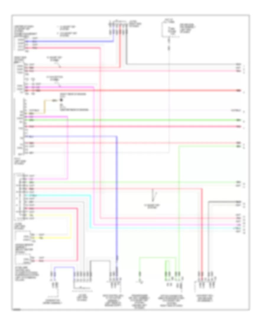
Computer Data Lines Wiring Diagram (1 of 2) for Toyota 4Runner Trail 2010
List of elements for Computer Data Lines Wiring Diagram (1 of 2) for Toyota 4Runner Trail 2010:
- (center of dash) (w/ smart key system) power management control ecu
- (right end of dash) ecm
- (right rear of engine) (4.0l) b1
- 2.7l
- 4.0l
- Air bag sensor assembly (below center of dash)
- B5 (2.7l) (center rear of engine)
- Bat
- C29
- Ca1h
- Ca1l
- Ca3n
- Ca3p
- Canh
- Canl
- Cann
- Canp
- Combination meter assembly
- Dlc 3 (left side of dash)
- Driver side r/b assembly (left end of dash)
- F10
- F33
- F50
- F53
- F80
- F88
- Hot at all times
- J/c a36 (left end of dash)
- J/c f59 (left end of dash)
- J/c f83 (right end of dash)
- Main body ecu (driver side j/b assembly)
- Obd fuse 7.5a
- Option connector (remote engine start) (w/o smart key system) (right end of dash)
- Pnk
- Rdg+
- Rdg-
- Red
- Sil
- Skid control ecu w/ actuator assembly (left rear of engine compt)
- Stabilizer control ecu (w/ kinetic dynamic suspension system) (left of steering column)
- System
- Tac
- Tach
- Transponder key ecu assembly (w/o smart key system) (center left of dash)
- W/ navigation system
- W/ smart key
- W/ smart key system
- W/o smart key
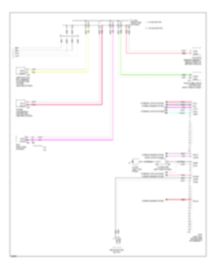
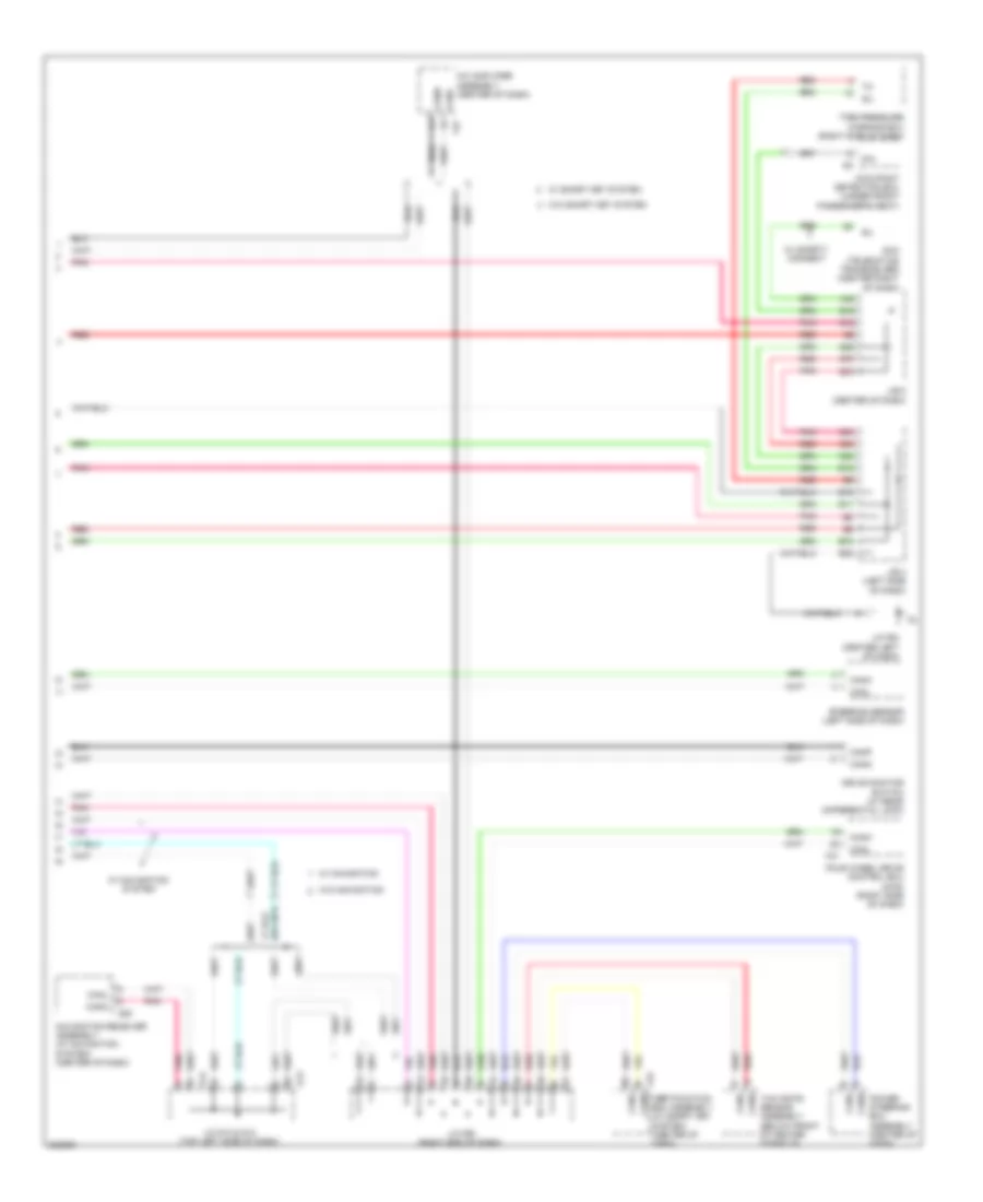
Computer Data Lines Wiring Diagram (2 of 2) for Toyota 4Runner Trail 2010
List of elements for Computer Data Lines Wiring Diagram (2 of 2) for Toyota 4Runner Trail 2010:
- A/c amplifier assembly (center of dash)
- A40
- B10
- B11
- B12
- B16
- B28
- B35
- B70
- B72
- C22
- C54
- C56
- Canh
- Canl
- Cann
- Canp
- Dcm (telematics transceiver) (center right of dash)
- Dia
- Drive monitor switch (w/ rear differential lock)
- F42
- F47
- F79 certification ecu assembly (w/ smart key system) (center of dash)
- Four wheel drive control ecu (4wd) (right side of dash)
- G13
- G14
- G20
- J/b 4 (left side of dash)
- J/b 5 (center of dash)
- J/c f60 (right end of dash)
- J/c f64 (center left of dash)
- J/c g13 & g14 (top left side of dash)
- Navigation receiver assembly (w/ navigation system) (center of dash)
- Occupant detection ecu (under front passenger's seat)
- Pnk
- Power steering ecu assembly (center of dash)
- Red
- Sil
- Steering sensor (left side of dash)
- Tire pressure warning ecu (right side of dash)
- W/ navigation
- W/ navigation system
- W/ safety connect
- W/ smart key system
- W/o navigation
- W/o smart key system
- Yaw rate sensor assembly (below front of center console)
CRUISE CONTROL
2.7L
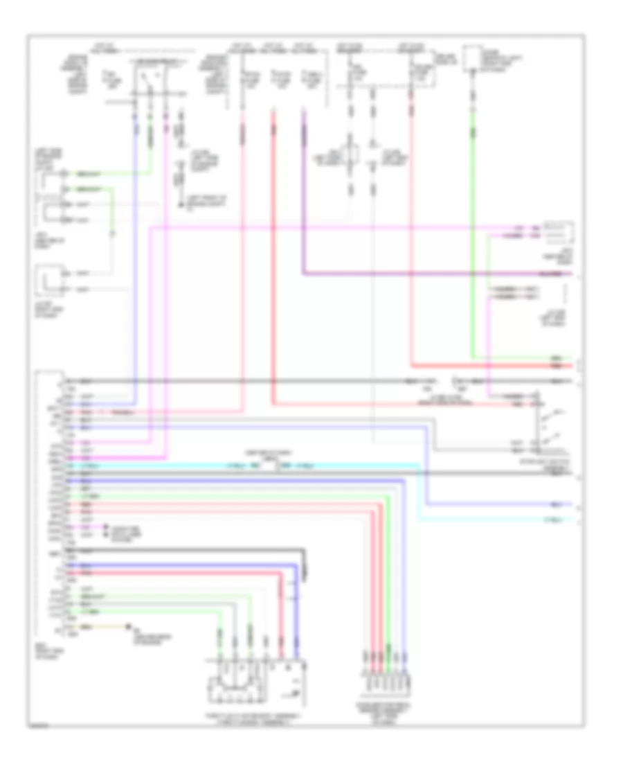
2.7L, Cruise Control Wiring Diagram (1 of 2) for Toyota 4Runner Trail 2010
List of elements for 2.7L, Cruise Control Wiring Diagram (1 of 2) for Toyota 4Runner Trail 2010:
- (center of dash) j/b 5
- (left front of engine compt) a1
- (left side of engine compt) j/c a39
- +bm
- A16
- A49
- Abs 2 fuse 30a
- Accelerator pedal sensor assembly (left side of dash)
- B25
- B27
- B36
- B38
- B39
- B5 (center rear of engine)
- B67
- Batt
- C15
- C51
- C55
- Canh
- Canl
- Ccs
- Computer data lines system
- D26
- Diode (backup light) (right end of dash)
- Driver side j/b
- Ecm (right end of dash)
- Efi fuse 25a
- Efi main relay
- Engine room j/b assembly (left side of engine compt)
- Engine room r/b assembly (left side of engine compt)
- Epa
- Epa2
- Eta
- Etcs fuse 10a
- F50
- F51
- F89
- Gauge fuse 7.5a
- Ge01
- Hot at all times
- Hot in on or start
- Ign fuse 10a
- Igsw
- J/b 4 (left side of dash)
- J/b 5 (center of dash)
- J/c a36 (left end of dash)
- J/c a38 (left side of engine compt)
- J/c b67 & f89 (right side of dash)
- J/c f57 (right end of dash)
- Mrel
- Nca
- Pnk
- Red
- Spd
- St1-
- Stop fuse 10a
- Stoplight switch assembly
- Stp
- Throttle w/ motor body assembly (throttle body assembly)
- Vcp2
- Vcpa
- Vcta
- Vpa
- Vpa2
- Vta
- Vta1
- Vta2
2.7L, Cruise Control Wiring Diagram (2 of 2) for Toyota 4Runner Trail 2010
List of elements for 2.7L, Cruise Control Wiring Diagram (2 of 2) for Toyota 4Runner Trail 2010:
- (left front wheel hub assembly) left front speed sensor
- (left rear wheel hub assembly) left rear speed sensor
- (right front wheel hub assembly) right front speed sensor
- (right rear wheel hub assembly) right rear speed sensor
- +bs
- +res
- -set
- A1 (left front of engine compt)
- B14
- B20
- B5 (center rear of engine)
- B52
- B63
- B64
- C16
- C36
- C58
- Cancel
- Canh
- Canl
- Combination meter assembly
- Computer data lines system
- Cruise control switch
- Cruise ind
- F23
- Fl+
- Fr+ fl-
- Fr-
- Gnd1
- J/b 4 (left side of dash)
- J/b 5 (center of dash)
- J/c f64 (center left of dash)
- On-off
- Park/neutral position switch (right side of transmission)
- Red
- Rl+
- Rl-
- Rr+
- Rr-
- Set ind
- Skid control ecu w/ actuator assembly (left rear of engine compt)
- Sp1
- Speedometer
- Spiral cable sub assembly (top of steering column)
4.0L
4.0L, Cruise Control Wiring Diagram (1 of 2) for Toyota 4Runner Trail 2010
List of elements for 4.0L, Cruise Control Wiring Diagram (1 of 2) for Toyota 4Runner Trail 2010:
- (center of dash) j/b 5
- (left front of engine compt) a1
- (left side of engine compt) j/c a39
- +b2
- +bm
- A16
- A49
- A64
- Abs 2 fuse 30a
- Accelerator pedal sensor assembly (left side of dash)
- B1 (right rear of engine)
- B25
- B27
- B35
- B36
- B38
- B59
- Batt
- C15
- C20
- C31
- C51
- C55
- Canh
- Canl
- Ccs
- Computer data lines system
- D26
- Driver side j/b
- Ecm (right end of dash)
- Ecu-ig1 fuse 10a
- Efi fuse 25a
- Efi main relay
- Engine room j/b assembly (left side of engine compt)
- Engine room r/b assembly (left side of engine compt)
- Epa
- Epa2
- Eta
- Etcs fuse 10a
- F50
- F51
- Gauge fuse 7.5a
- Ge01
- Hot at all times
- Hot in on or start
- Ign fuse 10a
- Igsw
- J/b 4 (left side of dash)
- J/b 5 (center of dash)
- J/c a36 (left end of dash)
- J/c a38 (left side of engine compt)
- J/c f57 (right end of dash)
- Mrel
- Nca
- Pnk
- Red
- Spd
- St1-
- Stop fuse 10a
- Stp
- Throttle w/ motor body assembly (throttle body assembly)
- Vcp2
- Vcpa
- Vcta
- Vpa
- Vpa2
- Vta
- Vta1
- Vta2
4.0L, Cruise Control Wiring Diagram (2 of 2) for Toyota 4Runner Trail 2010
List of elements for 4.0L, Cruise Control Wiring Diagram (2 of 2) for Toyota 4Runner Trail 2010:
- (left front wheel hub assembly) left front speed sensor
- (left rear wheel hub assembly) left rear speed sensor
- (right front wheel hub assembly) right front speed sensor
- (right rear wheel hub assembly) right rear speed sensor
- +bs
- +res
- -set
- A1 (left front of engine compt)
- B1 (right rear of engine)
- B14
- B20
- B52
- B63
- B64
- C16
- C36
- C58
- Cancel
- Canh
- Canl
- Combination meter assembly
- Computer data lines system
- Cruise control switch
- Cruise ind
- F23
- Fl+
- Fr+ fl-
- Fr-
- Gnd1
- J/b 4 (left side of dash)
- J/b 5 (center of dash)
- J/c f64 (center left of dash)
- On-off
- Park/neutral position switch (right side of transmission)
- Red
- Rl+
- Rl-
- Rr+
- Rr-
- Set ind
- Skid control ecu w/ actuator assembly (left rear of engine compt)
- Sp1
- Speedometer
- Spiral cable sub assembly (top of steering column)
DEFOGGERS
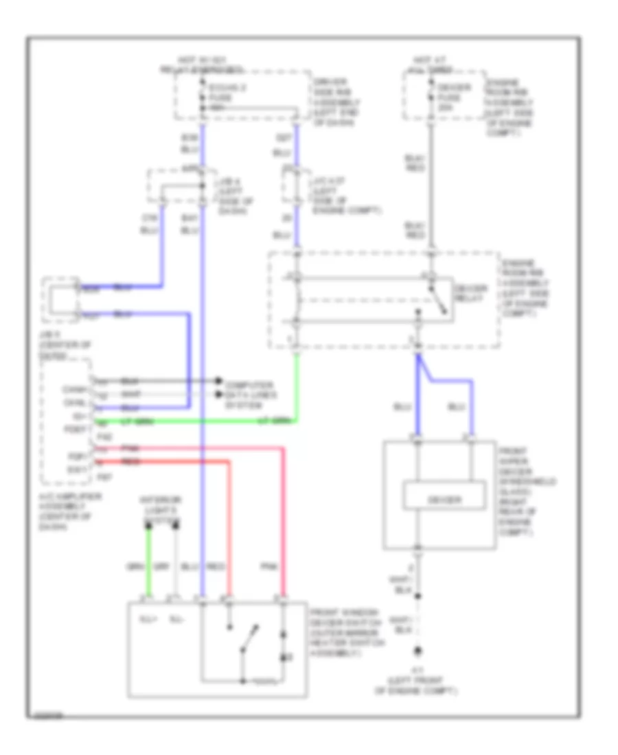
Front Deicer Wiring Diagram for Toyota 4Runner Trail 2010
List of elements for Front Deicer Wiring Diagram for Toyota 4Runner Trail 2010:
- A/c amplifier assembly (center of dash)
- A1 (left front of engine compt)
- A27
- A66
- B26
- B39
- B41
- C19
- Canh
- Canl
- Computer data lines system
- D27
- Deicer
- Deicer fuse 20a
- Deicer relay
- Driver side r/b assembly (left end of dash)
- Ecu-ig 2 fuse 10a
- Engine room r/b assembly (left side of engine compt)
- F42
- F87
- Fdef
- Fdfi
- Front window deicer switch (outer mirror heater switch assembly)
- Front wiper deicer (windshield glass) (right rear of engine compt)
- Hot at all times
- Hot w/ ig1 relay energized
- Ig+
- Ill+
- Ill-
- Interior lights system
- J/b 4 (left side of dash)
- J/b 5 (center of dash)
- J/c a37 (left side of engine compt)
- Pnk
- Red
- Sw1
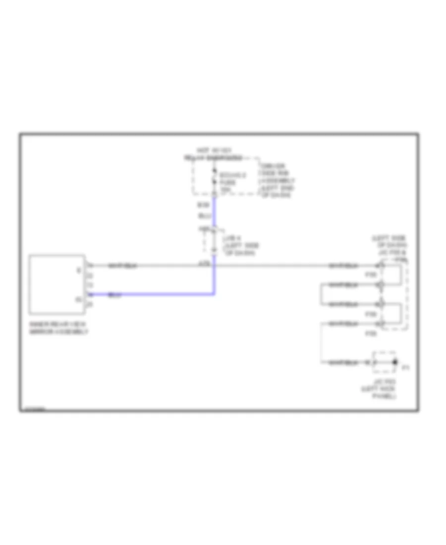
Mirror Heater & Rear Defogger Wiring Diagram for Toyota 4Runner Trail 2010
List of elements for Mirror Heater & Rear Defogger Wiring Diagram for Toyota 4Runner Trail 2010:
- A/c amplifier assembly (center of dash)
- A1 (left front of engine compt)
- C27
- C28
- Canh
- Canl
- Computer data lines system
- D27
- D31
- D32
- Def fuse 30a
- Def relay
- Driver side r/b assembly (left end of dash)
- Ecu-ig 1 fuse 10a
- Ecu-ig 2 fuse 10a
- Engine room r/b assembly (left side of engine compt)
- F42
- H1 (rear of right front door)
- Heater control assembly
- Hl+
- Hl-
- Hot at all times
- Hot w/ ig 1 relay energized
- Hr+
- Hr-
- I1 (rear of left front door)
- J/c a36 (left end of dash)
- J/c a37 (left side of engine compt)
- J/c a38 (left side of engine compt)
- J/c h8 (front of right front door)
- J/c i8 (front of left front door)
- Left outer rear view mirror assembly
- Lin1
- Mhtr
- Mir htr fuse 10a
- Mir htr relay
- Mirror heater
- Noise filter
- O2 (base of left "d" pillar)
- Outer rear view mirror
- Pnk
- Rdef
- Rear window defogger & mirror heater switch
- Rear window defogger (back door glass) (rear window)
- Right outer rear view mirror assembly
- W/ turn signal light
- W/o turn signal light
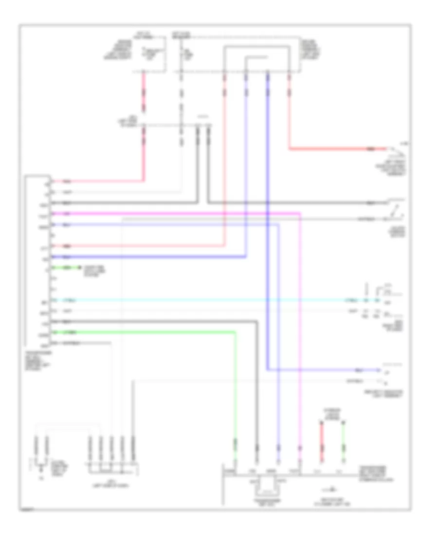
ELECTRONIC POWER STEERING
Electronic Power Steering Wiring Diagram for Toyota 4Runner Trail 2010
List of elements for Electronic Power Steering Wiring Diagram for Toyota 4Runner Trail 2010:
- (center left of dash)
- (center left of dash) j/c f64
- A30
- A36
- A64
- A66
- A68
- B14
- B22
- B35
- B63
- Bat
- C20
- C31
- C55
- Canh
- Canl
- Combination meter assembly
- Computer data lines system
- D39
- Driver side j/b
- Ecu-b fuse 10a
- Ecu-ig 1 fuse 10a
- Engine room r/b assembly (left side of engine compt)
- Ess
- Gauge fuse 7.5a
- Gnd
- Hot at all times
- Hot in on or start
- Ig+
- J/b 4 (left side of dash)
- J/b 5 (center of dash)
- J/c f64
- J/c f64 (center left of dash)
- Power steering ecu assembly (center of dash)
- Power steering ind
- Red
- Sof+
- Sof-
- Solenoid valve assembly (2.7l: left side of engine) (4.0l: right front of engine)
- Steering sensor (left side of dash)
ELECTRONIC SUSPENSION
Electronic Suspension Wiring Diagram for Toyota 4Runner Trail 2010
List of elements for Electronic Suspension Wiring Diagram for Toyota 4Runner Trail 2010:
- (left "b" pillar) o1
- A33
- A66
- A68
- Accumulator housing assembly (base of left "b" pillar)
- Aug
- B14
- B15
- B20
- B22
- B63
- Becu
- C55
- Canh
- Canl
- Combination meter assembly
- Computer data lines system
- D39
- Driver side j/b
- Ecu-b fuse 10a
- Engine room r/b assembly (left side of engine compt)
- F27
- F55
- F56
- Flcy
- Frcy
- Gauge fuse 7.5a
- Gnd
- Hot at all times
- Hot in on or start
- J/b 4 (left side of dash)
- J/b 5 (center of dash)
- J/c f55 & f56 (left side of dash)
- J/c f63 (left kick panel)
- J/c f64 (center left of dash)
- J/c n22 (above right rear wheelwell)
- J/c o18 (base of left "c" pillar)
- Kdss fuse 10a
- Kdss ind
- Lcty
- Left front door courtesy light switch assembly
- Left rear door courtesy light switch assembly
- Main body ecu
- Pnk
- Rcty
- Red
- Right front door courtesy light switch assembly
- Right rear door courtesy light switch assembly
- Sbp1
- Sgp1
- Slal
- Slau
- Sop1
- Stabilizer control ecu (left of steering column)
- Stabilizer control w/
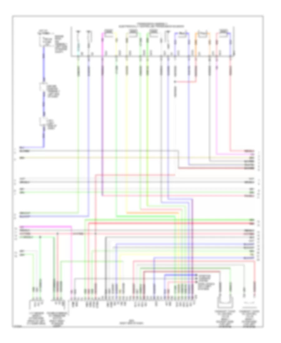
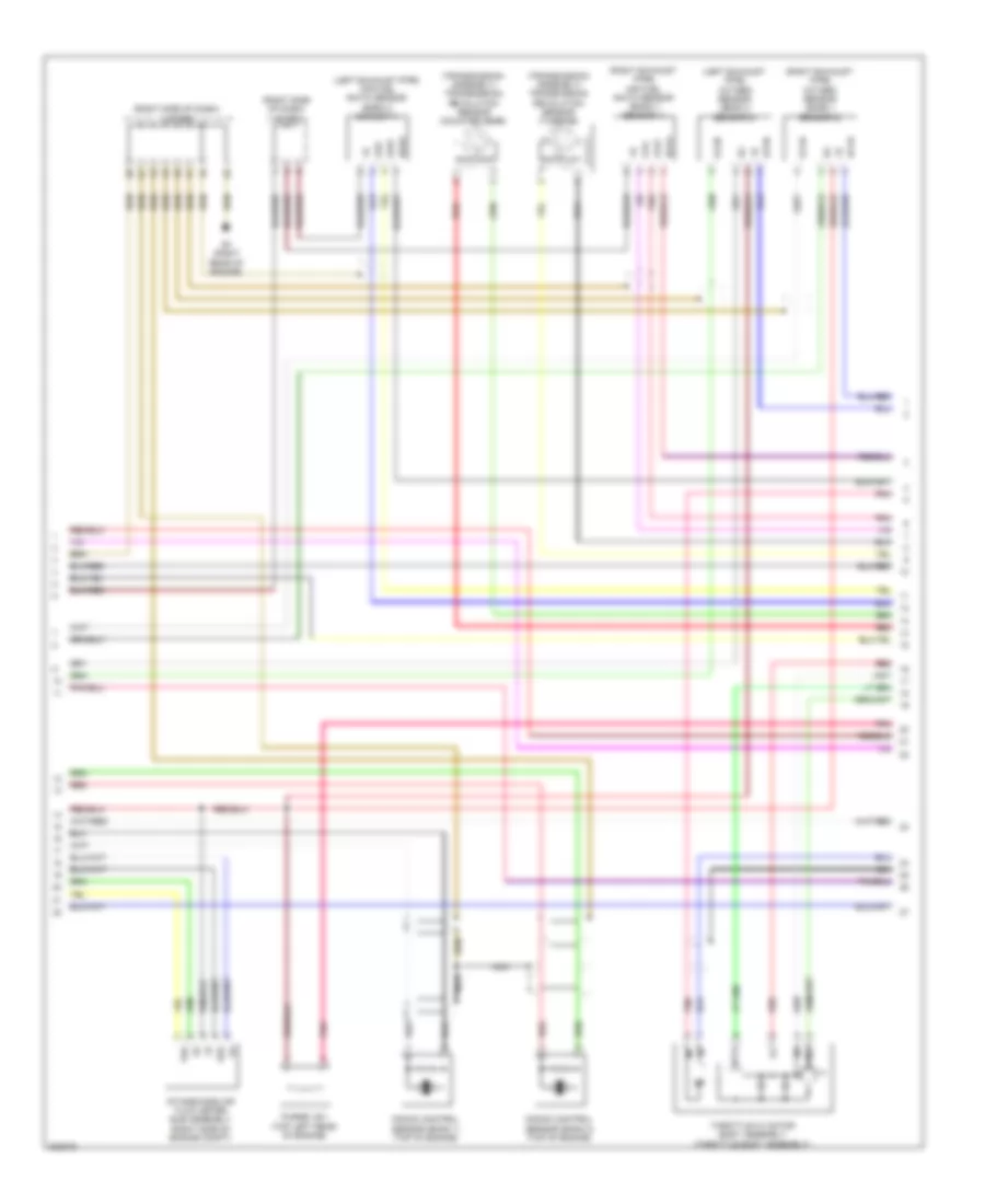
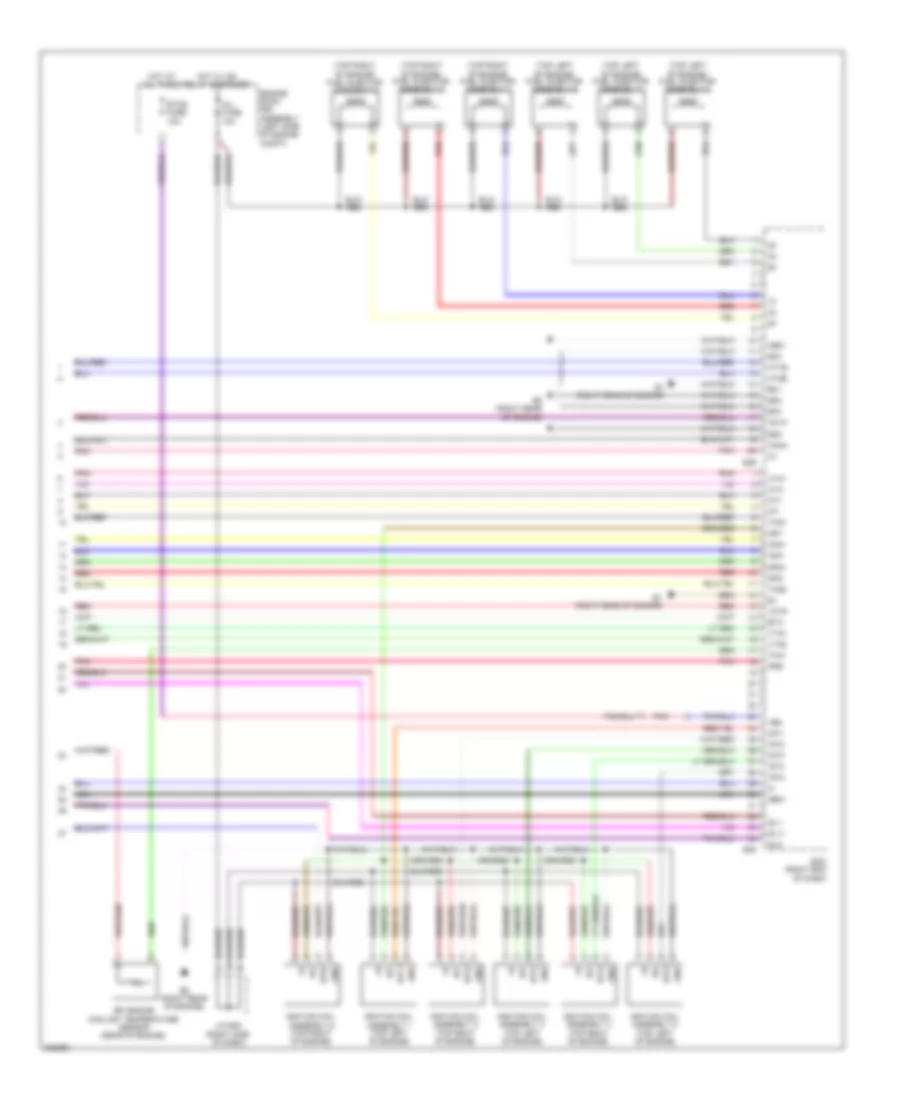
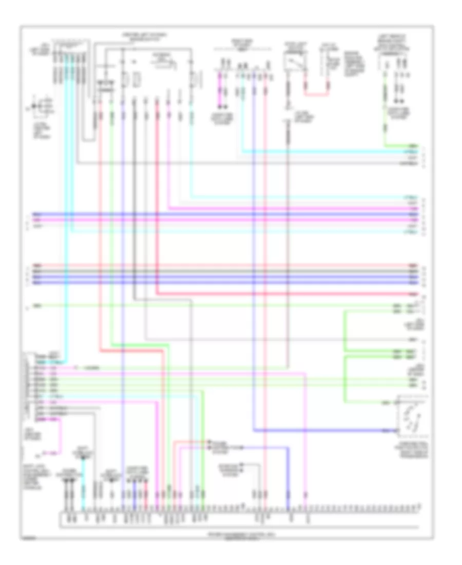
ENGINE PERFORMANCE
2.7L
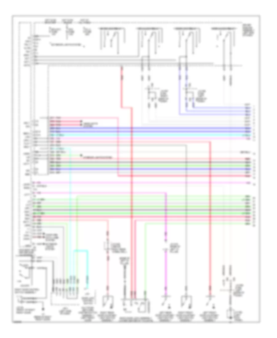
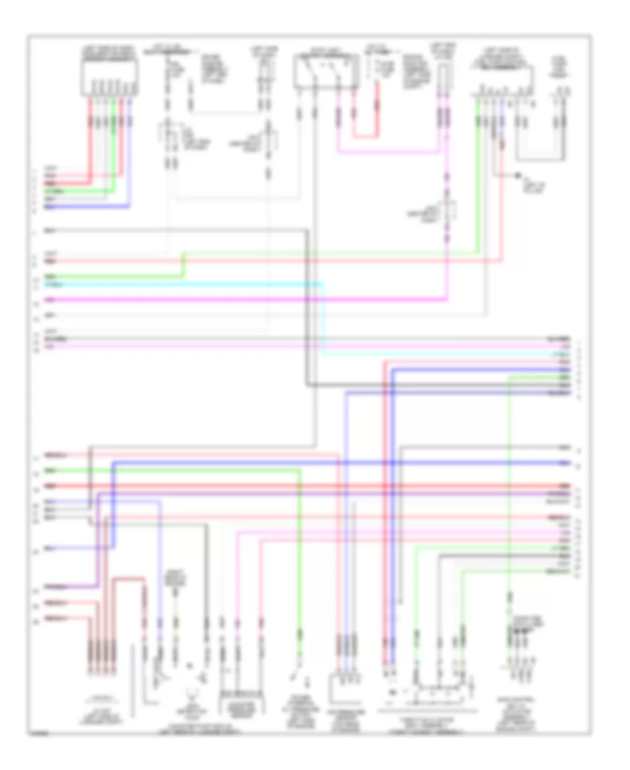
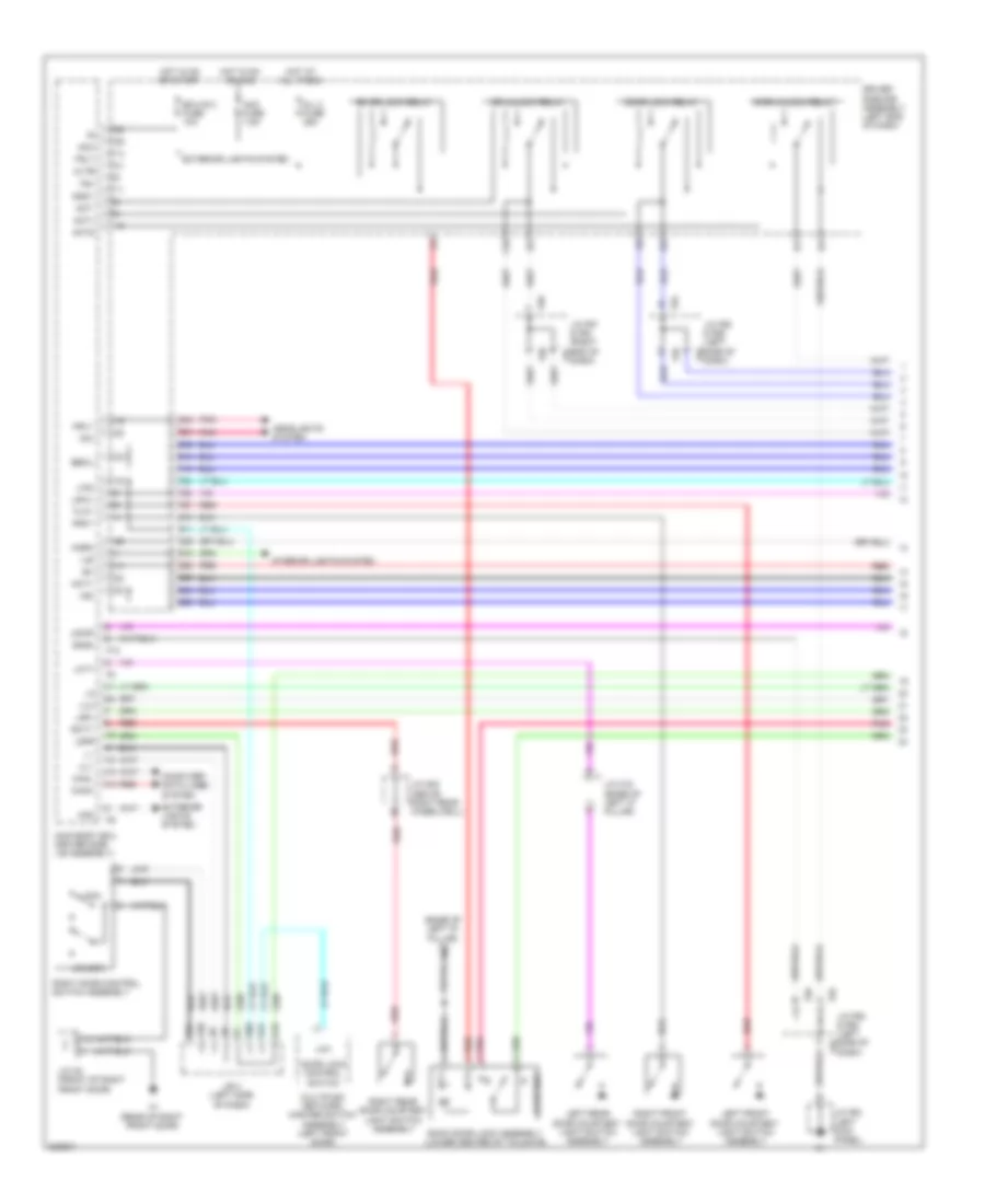
2.7L, Engine Performance Wiring Diagram (1 of 6) for Toyota 4Runner Trail 2010
List of elements for 2.7L, Engine Performance Wiring Diagram (1 of 6) for Toyota 4Runner Trail 2010:
- (left side of luggage compt) j/c a38
- +bm
- A/f fuse 20a
- A/f relay
- A1 (left front of engine compt)
- A10
- A66
- Ac1
- Act
- Aidi
- Aip
- Air conditioning system
- Air injection control driver (left side of engine compt)
- Air switching valve (right rear of engine)
- Airp
- Airv
- Anti-theft system
- B10
- B10 (center rear of engine)
- B9 (center rear of engine)
- Batt
- C/opn relay
- Canh
- Canl
- Ccs
- Computer data lines system
- Computer data lines system cruise control system
- Ecm (right end of dash)
- Ef1 2 fuse 7.5a
- Efi fuse 25a
- Efi main relay
- Engine room j/b assembly (left side of engine compt)
- Engine room r/b assembly (left side of engine compt)
- Epa
- Epa2
- F50
- F51
- Fpc
- Gnd
- Hot at all times
- Igsw
- Imi
- Imo
- Inlet air pump (right front of engine compt)
- J/b 5 (center of dash)
- J/c a39 (left side of luggage compt)
- J/c f57 (right end of dash)
- J/c f64 (center left of dash)
- J/c f65 (right kick panel)
- Mpmp
- Mrel
- Pnk
- Psw
- Red
- Sip
- Siv
- Spd
- St1-
- Stp
- Tach
- Vcp2
- Vcpa
- Vpa
- Vpa2
- Vpmp
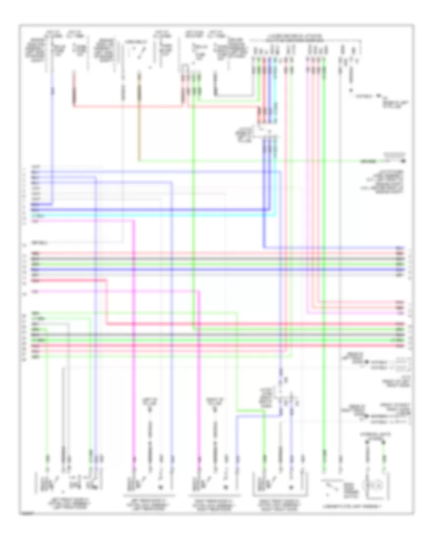
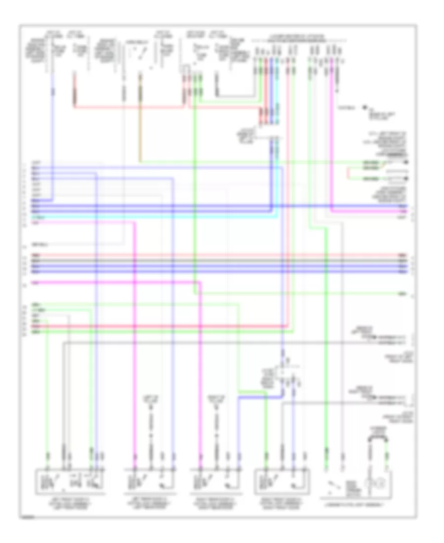
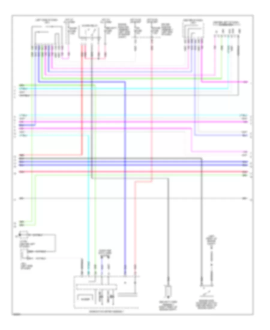
2.7L, Engine Performance Wiring Diagram (2 of 6) for Toyota 4Runner Trail 2010
List of elements for 2.7L, Engine Performance Wiring Diagram (2 of 6) for Toyota 4Runner Trail 2010:
- (fuel tank) fuel pump
- (left end of dash) j/c a36
- (left side of dash) accelerator pedal sensor assembly
- (left side of dash) j/b 4
- (left side of luggage compt) fuel pump control ecu assembly
- (right rear of engine) b1
- A16
- A49
- Aip
- Air pressure sensor (top rear of engine)
- B27
- C15
- C51
- Canh
- Canister pressure sensor
- Canister pump module (left rear of luggage compt)
- Canl
- Computer data lines system
- D26
- Driver side r/b assembly (left end of dash)
- Engine room r/b assembly (left side of engine compt)
- Epa
- Epa2
- Fp-
- Fpc
- Hot at all times
- Hot w/ ig2 relay energized
- Ign fuse 10a
- J/b 5 (center of dash)
- J/c a36 (left end of dash)
- J/c a37 (left side of luggage compt)
- Leak detection pump
- Mgnd
- Mtrb
- Nca
- O1 (left "b" pillar)
- Pnk
- Power steering oil pressure switch (left side of engine)
- Red
- Sgnd
- Skid control ecu w/ actuator assembly (left rear of engine compt)
- Sp1
- Stop fuse 10a
- Stop light switch assembly
- Throttle w/ motor body assembly (throttle body assembly)
- Vcc
- Vcp2
- Vcpa
- Vent valve
- Vgnd
- Vlvb
- Vout
- Vpa
- Vpa2
- Vta
- Vta2
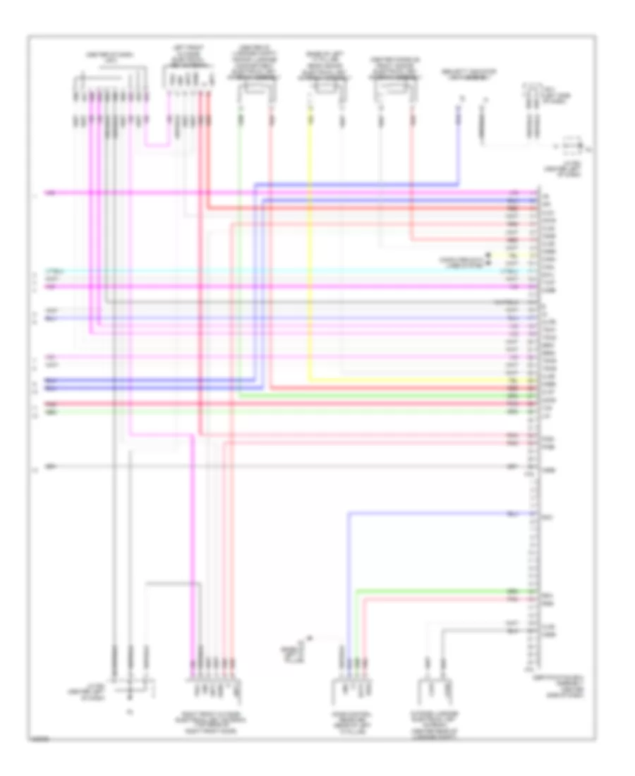
2.7L, Engine Performance Wiring Diagram (3 of 6) for Toyota 4Runner Trail 2010
List of elements for 2.7L, Engine Performance Wiring Diagram (3 of 6) for Toyota 4Runner Trail 2010:
- A/t oil ind
- A68
- Air pmp fuse 50a
- Alt
- B14
- B20
- B22
- B25
- B36
- Buzzer
- C16
- C55
- Canh
- Canl
- Chk
- Combination meter assembly
- Computer data lines system
- D39
- Driver side r/b assembly (left end of dash)
- E2g
- Ecm (right end of dash)
- Ecu-b fuse 10a
- Efi engine coolant temperature sensor (top left of engine)
- Eknk
- Engine room r/b assembly (left side of engine compt)
- Eppm
- Eta
- Etcs fuse 10a
- Etha
- Ethw
- F56
- Gauge fuse 7.5a
- Hot at all times
- Hot w/ ig2 relay energized
- Ig+
- Intake mass air flow meter sub assembly (right side of luggage compt)
- J/b 4 (left side of dash)
- J/b 5 (center of dash)
- J/c f55 & f56 (left side f55 of dash)
- J/c f63 (left kick panel)
- Knk1
- Knock control sensor (bank 1)
- Lcd
- Malfunction indicator lamp
- Mgnd
- Nca
- Pnk
- Ppmp
- Red
- Starting/ charging system
- Tha
- Thoc
- Thw
- Vcpp
- Vcta
- Vta1
- Vta2
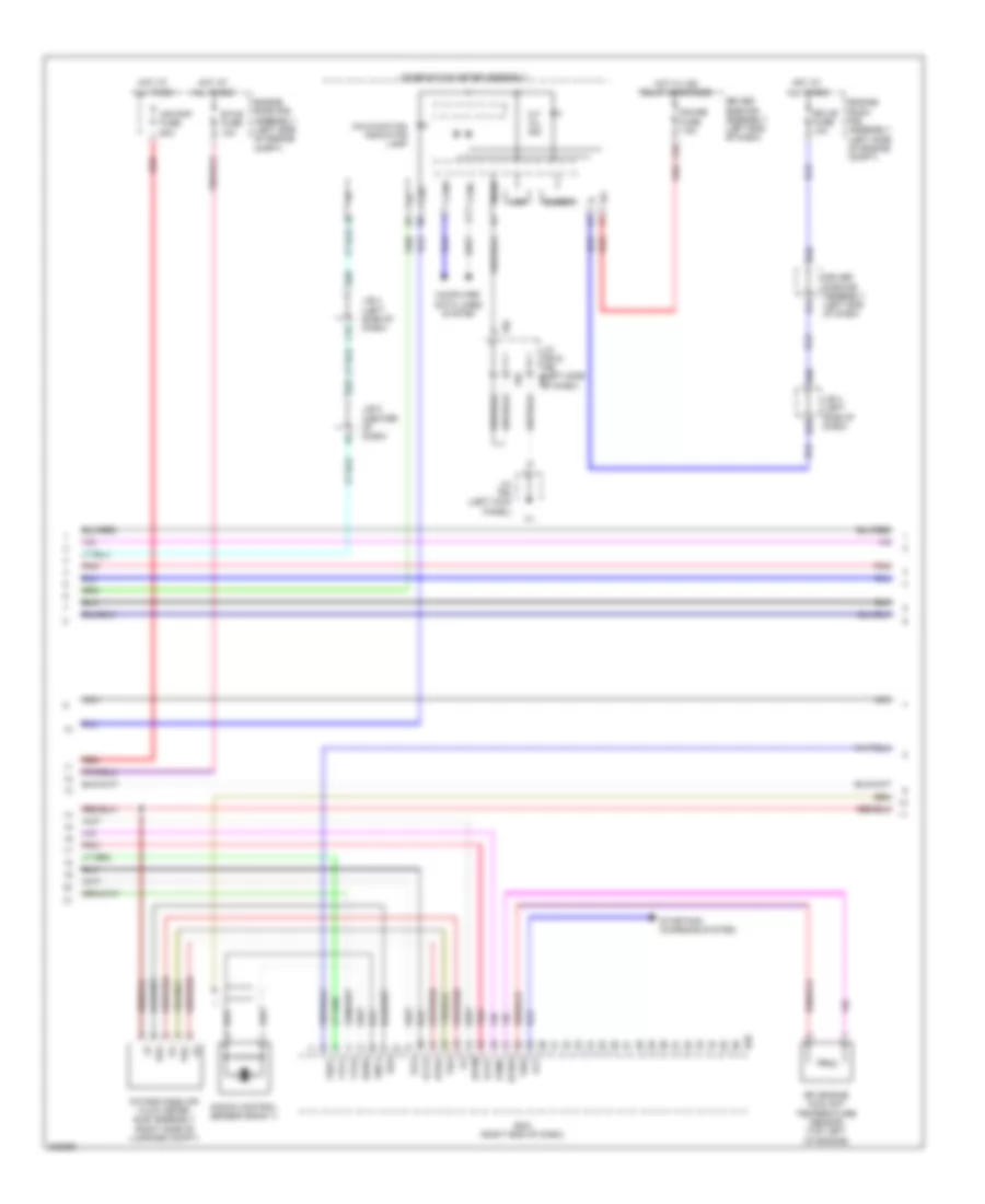
2.7L, Engine Performance Wiring Diagram (4 of 6) for Toyota 4Runner Trail 2010
List of elements for 2.7L, Engine Performance Wiring Diagram (4 of 6) for Toyota 4Runner Trail 2010:
- (left side of dash) j/b 4
- (right end of dash) diode (backup light)
- (right side of dash) j/c b66
- (right side of transmission) park/neutral position switch
- A50
- A64
- Acc
- Acc fuse 7.5a
- B17
- B35
- B37
- B56
- B59
- B67
- C20
- C31
- C53
- Cam timing oil control valve (left front of engine)
- Camshaft position sensor (front of cylinder head)
- Crankshaft position sensor (left front of engine)
- Driver side r/b assembly (left end of dash)
- Ecm (right end of dash)
- Ecu ig 1 fuse 10a
- Etho
- Gnd
- Hot w/ ig 1 relay energized
- Ig1
- J/b 5 (center of dash)
- Nca
- Ne+
- Ne-
- Oc1+
- Oc1-
- Pnk
- Red
- Slt+
- Slt-
- Starting/charging system
- Temperature sensor (left rear of engine)
- Tho1
- Vcap
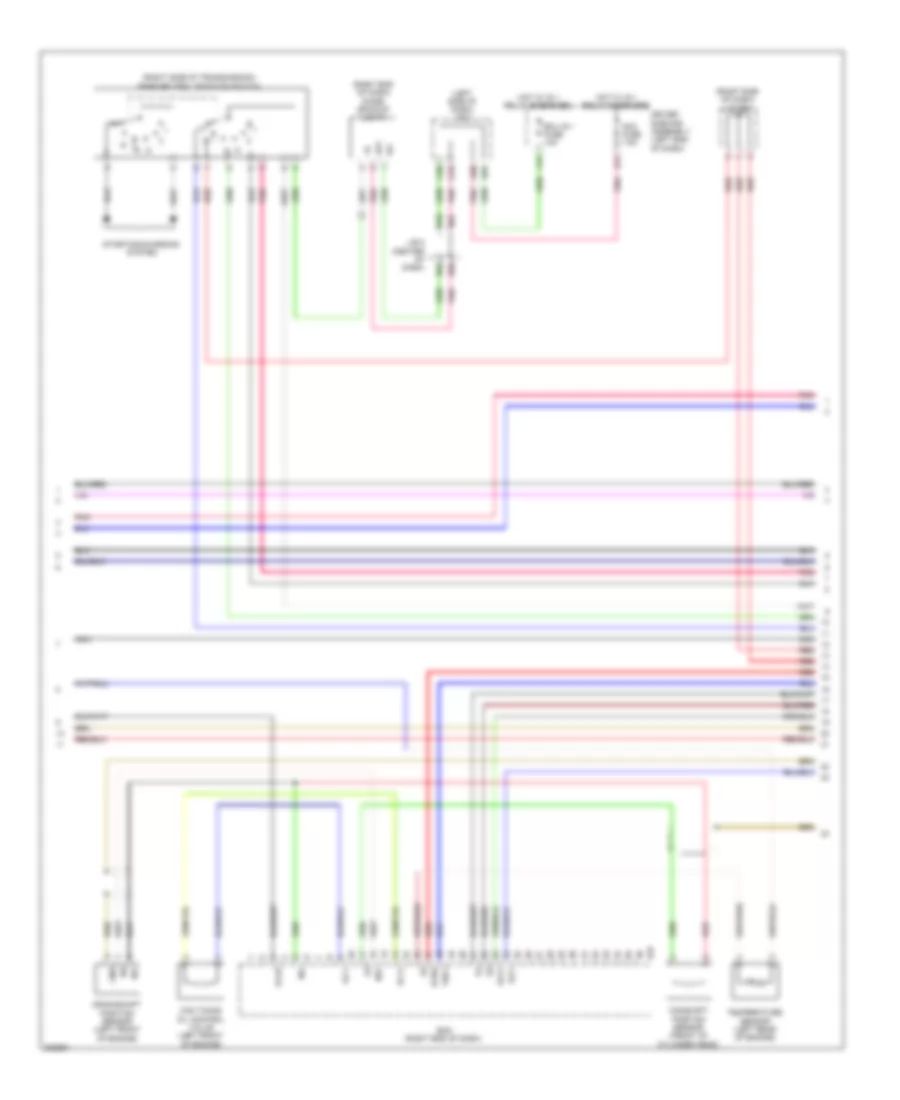
2.7L, Engine Performance Wiring Diagram (5 of 6) for Toyota 4Runner Trail 2010
List of elements for 2.7L, Engine Performance Wiring Diagram (5 of 6) for Toyota 4Runner Trail 2010:
- (center rear of engine) b5
- (on exhaust pipe) air fuel ratio sensor (bank 1 sensor 1)
- (top left of engine) fuel injector assembly 1
- (top left of engine) fuel injector assembly 2
- (top left of engine) fuel injector assembly 3
- (top left of engine) fuel injector assembly 4
- A1a+
- A1a-
- Electronically controlled transmission solenoid (transmission assembly)
- Engine room r/b assembly (left side of engine compt)
- Ha1a
- Hot w/ ig2 relay energized
- Ht1b
- Inj fuse 10a
- J/c b66 (right side of dash)
- Nca
- Ot2+
- Ot2-
- Ox1b
- Oxygen sensor (bank 1 sensor 2) (on exhaust pipe)
- Pnk
- Purge vsv (top left side of engine)
- Red
- Slt+
- Slt-
- Slu+
- Slu-
- Transmission revolution sensor (counter gear) (transmission assembly)
- Transmission revolution sensor (turbine) (transmission assembly)
2.7L, Engine Performance Wiring Diagram (6 of 6) for Toyota 4Runner Trail 2010
List of elements for 2.7L, Engine Performance Wiring Diagram (6 of 6) for Toyota 4Runner Trail 2010:
- (center rear of engine) b9
- (rear of engine) noise filter (ignition coil)
- (top of engine) ignition coil assembly 1
- (top of engine) ignition coil assembly 2
- (top of engine) ignition coil assembly 3
- (top of engine) ignition coil assembly 4
- A1a+
- A1a-
- A65
- At3
- Atd
- B10 (center rear of engine)
- B38
- B39
- B5 (center rear of engine)
- B57
- B6 (center rear of engine)
- B67
- B9 (center rear of engine)
- C29
- C32
- C52
- C58
- E01
- E02
- E04
- Eaip
- Ecm (right end of dash)
- Ex1b
- F89
- Ge01
- Gnd
- Ha1a
- Ht1b
- Igf
- Igf1
- Igt1
- Igt2
- Igt3
- Igt4
- Ill+
- Ill-
- Interior lights system
- J/b 5 (center of dash)
- J/c b67 & f89 (right side of dash)
- J/c f64 (center left of dash)
- Me01
- Nca
- Nco+
- Nco-
- Nssd
- Ox1b
- Pnk
- Prg
- Red
- Shift lock control ecu sub assembly (under center console)
- Shift position indicator
- Slu+
- Slu-
- Sp2+
- Sp2-
- Transmission control switch
4.0L
4.0L, Engine Performance Wiring Diagram (1 of 6) for Toyota 4Runner Trail 2010
List of elements for 4.0L, Engine Performance Wiring Diagram (1 of 6) for Toyota 4Runner Trail 2010:
- (left front of engine compt) a1
- (left side of luggage compt) j/c a38
- +b2
- 4wd
- A/f fuse 20a
- A/f relay
- A66
- Ac1
- Act
- Air conditioning system
- Air conditioning system computer data lines system
- Anti-theft system
- B10
- Batt
- C/opn relay
- Canh
- Canl
- Cann
- Canp
- Ccs
- Computer data lines system
- Cruise control system
- Ecm (right end of dash)
- Ef1 2 fuse 7.5a
- Efi fuse 25a
- Efi main relay
- Els2
- Engine room j/b assembly (left side of engine compt)
- Engine room r/b assembly (left side of engine compt)
- Epa
- Epa2
- F50
- F51
- Fp-
- Fpc
- Fuel pump (fuel tank)
- Fuel pump control ecu assembly (left side of luggage compt)
- Hot at all times
- Igsw
- Imi
- Imo
- J/b 5 (center of dash)
- J/c a39 (left side of engine compt)
- J/c f57 (right end of dash)
- J/c f64 (center left of dash)
- Mpmp
- Mrel
- O1 (left "b" pillar)
- Pnk
- Red
- Sftd
- Sftu
- Spd
- St1-
- Sta
- Starting/charging system
- Stp
- Tach
- Tfn
- Vcp2
- Vcpa
- Vpa
- Vpa2
- Vpmp
4.0L, Engine Performance Wiring Diagram (2 of 6) for Toyota 4Runner Trail 2010
List of elements for 4.0L, Engine Performance Wiring Diagram (2 of 6) for Toyota 4Runner Trail 2010:
- (front of engine) (4wd) differential vacuum actuator assembly
- (left end of dash) j/c a36
- (left side of dash) accelerator pedal sensor assembly
- (left side of dash) j/b 4
- (right rear of engine) b1
- (right side of cargo area) voltage inverter assembly
- (right side of dash) four wheel drive control ecu
- (transmission assembly) (4wd) transfer indicator switch (neutral position)
- A16
- A49
- A65
- B2 (right rear of engine)
- B27
- B50
- B54
- C15
- C51
- C54
- Canh
- Canister pressure sensor
- Canister pump module (left rear of luggage compt)
- Canl
- Computer data lines system
- D26
- Driver side r/b assembly (left end of dash)
- Engine room r/b assembly (left side of engine compt)
- Epa
- Epa2
- Ex+
- Ex-
- Excd
- F47
- Hot at all times
- Hot w/ ig2 relay energized
- Ign fuse 10a
- J/b 5 (center of dash)
- J/c a36 (left end of dash)
- J/c a37 (left side of engine compt)
- J/c f64 (center left of dash)
- Leak detection pump
- Mgnd
- Mtrb
- N19
- Pnk
- Red
- Sftd
- Sftu
- Sgnd
- Skid control ecu w/ actuator assembly (left rear of engine compt)
- Sp1
- Stop fuse 10a
- Stop light switch assembly
- Transmission control switch (center console)
- Vc2
- Vcc
- Vcp2
- Vcpa
- Vent valve
- Vgnd
- Vlvb
- Vout
- Vpa
- Vpa2
- Vvr+
- Vvr-
- Vvt sensor (bank1 exhaust side) (right side of engine)
- Vvt sensor (bank1 intake side) (front of right cylinder head)
4.0L, Engine Performance Wiring Diagram (3 of 6) for Toyota 4Runner Trail 2010
List of elements for 4.0L, Engine Performance Wiring Diagram (3 of 6) for Toyota 4Runner Trail 2010:
- (center of dash) j/b 5
- (right side of transmission) park/neutral position switch
- A/t oil ind
- A64
- B20
- B25
- B35
- B36
- B59
- Buzzer
- C16
- C20
- C31
- C55
- C57
- Camshaft timing oil control valve (bank 2 exhaust side) (top right of engine)
- Camshaft timing oil control valve (bank 2 intake side) (top right of engine)
- Canh
- Canl
- Chk
- Combination meter assembly
- Computer data lines system
- Crankshaft position sensor (left front of engine)
- Driver side r/b assembly (left end of dash)
- Ecm (right end of dash)
- Ecu ig 1 fuse 10a
- Ev1+
- Ev1-
- Ev2+
- Ev2-
- Ex+
- Ex-
- Ex1b
- Ex2b
- F56
- Gauge fuse 7.5a
- Hot w/ ig 1 relay energized
- Hot w/ ig2 relay energized
- Ig+
- J/b 4 (left side of dash)
- J/b 5 (center of dash)
- J/c b48 (right side of dash)
- J/c f55 & f56 (left side f55 of dash)
- J/c f63 (left kick panel)
- Lcd
- Malfunction indicator lamp
- Mgnd
- Ne+
- Ne-
- Oc2+
- Oc2-
- Oe2+
- Oe2-
- Ox1b
- Ox2b
- Pnk
- Red
- Starting/charging system
- Vcv1
- Vcv2
- Vv1+
- Vv1-
- Vv2+
- Vv2-
- Vvt sensor (bank 2 exhaust side) (left side of engine)
4.0L, Engine Performance Wiring Diagram (4 of 6) for Toyota 4Runner Trail 2010
List of elements for 4.0L, Engine Performance Wiring Diagram (4 of 6) for Toyota 4Runner Trail 2010:
- (transmission assembly) electronically controlled transmission solenoid
- A68
- Alt
- B14
- B22
- B37
- Camshaft timing oil control valve (bank 1 exhaust side) (top left of engine)
- Camshaft timing oil control valve (bank 1 intake side) (top left of engine)
- D39
- Door locks & anti-theft systems
- Driver side r/b assembly (left end of dash)
- E2g
- Ecm (right end of dash)
- Ecu-b fuse 10a
- Ekn2
- Eknk
- Engine room r/b assembly (left side of engine compt)
- Etha
- Ethw
- Hot at all times
- Igt6
- J/b 4 (left side of dash)
- Knk1
- Knk2
- Neo
- Nsw
- Oc1+
- Oc1-
- Oe1+
- Oe1-
- Ot+
- Ot-
- Ot2+
- Ot2-
- Pnk
- Power steering oil pressure switch (right front of engine compt)
- Ppmp
- Psp
- Red
- Sl1+
- Sl1-
- Sl2+
- Sl2-
- Slt+
- Slt-
- Slu+
- Slu-
- Starting/ charging system
- Tha
- Vvl+
- Vvl-
- Vvt sensor (bank 2 intake side) (front of left cylinder head)
4.0L, Engine Performance Wiring Diagram (5 of 6) for Toyota 4Runner Trail 2010
List of elements for 4.0L, Engine Performance Wiring Diagram (5 of 6) for Toyota 4Runner Trail 2010:
- (left exhaust pipe) air fuel ratio sensor (bank 2 sensor 1)
- (left exhaust pipe) oxygen sensor (bank 2 sensor 2)
- (right exhaust pipe) air fuel ratio sensor (bank 1 sensor 1)
- (right exhaust pipe) oxygen sensor (bank 1 sensor 2)
- (right side of dash) j/c b48
- (right side of dash) j/c b49
- (transmission assembly) transmission revolution sensor (counter gear)
- (transmission assembly) transmission revolution sensor (turbine)
- A1a+
- A1a-
- A2a+
- A2a-
- B1 (right rear of engine)
- E2g
- Ha1a
- Ha2a
- Ht1b
- Ht2b
- Intake mass air flow meter sub assembly (right side of engine compt)
- Knock control sensor (bank 1) (top of engine)
- Knock control sensor (bank 2) (top of engine)
- Nca
- Ox1b
- Ox2b
- Pnk
- Purge vsv (top left rear of engine)
- Red
- Tha
- Throttle w/ motor body assembly (throttle body assembly)
- Vta
- Vta2
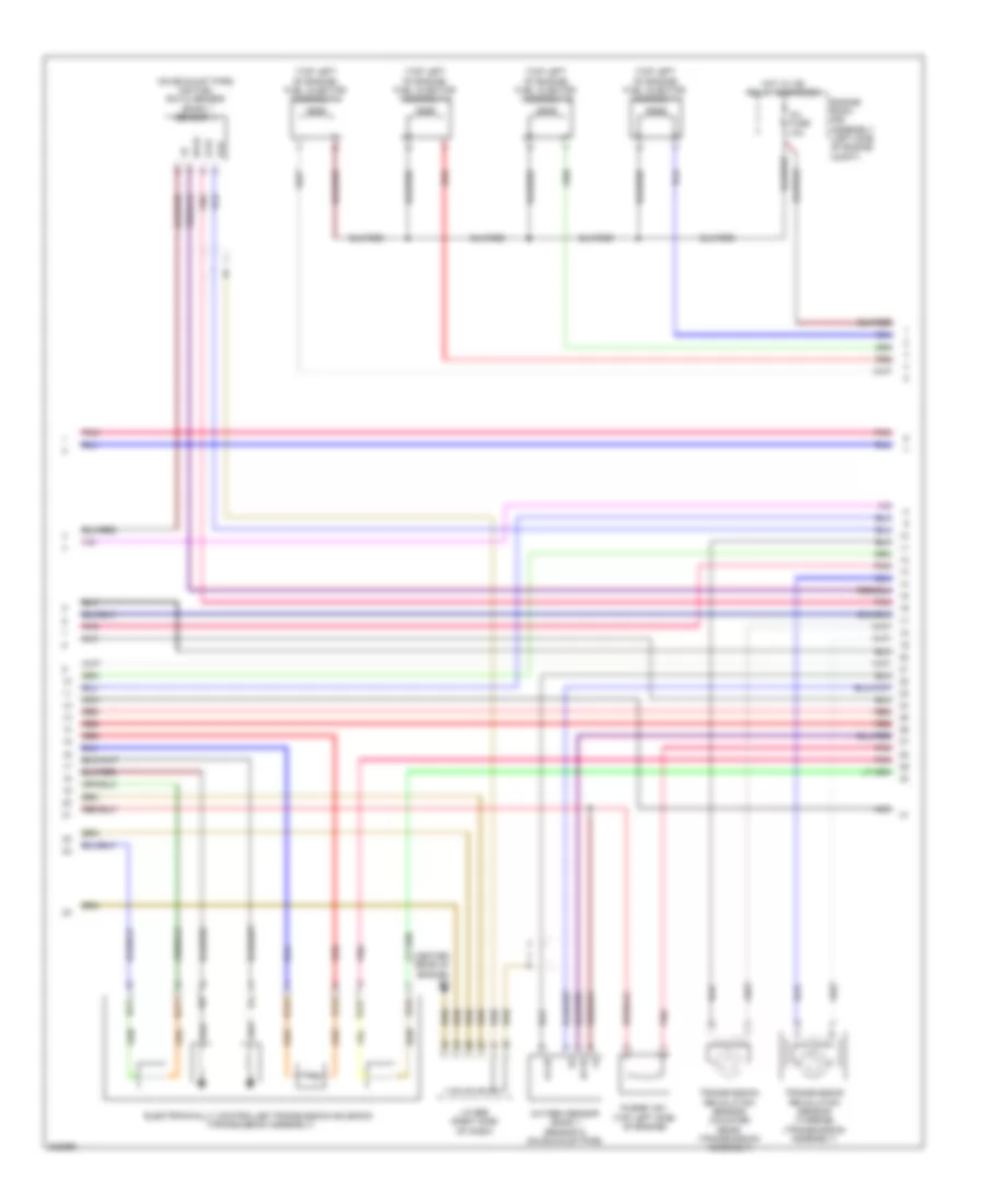
4.0L, Engine Performance Wiring Diagram (6 of 6) for Toyota 4Runner Trail 2010
List of elements for 4.0L, Engine Performance Wiring Diagram (6 of 6) for Toyota 4Runner Trail 2010:
- (top left of engine) fuel injector assembly 2
- (top left of engine) fuel injector assembly 4
- (top left of engine) fuel injector assembly 6
- (top right of engine) fuel injector assembly 1
- (top right of engine) fuel injector assembly 3
- (top right of engine) fuel injector assembly 5
- +bm
- A1a+
- A1a-
- A2a+
- A2a-
- B1 (right rear of engine)
- B2 (right rear of engine)
- B38
- B39
- E01
- E02
- E03
- E04
- E05
- Ecm (right end of dash)
- Efi engine coolant temperature sensor (rear of engine)
- Engine room r/b assembly (left side of engine compt)
- Eta
- Etcs fuse 10a
- Ge01
- Gnd
- Ha1a
- Ha2a
- Hot at all times
- Hot w/ ig2 relay energized
- Ht1b
- Ht2b
- Igf
- Igf1
- Ignition coil assembly 1 (top left of engine)
- Ignition coil assembly 2 (top right of engine)
- Ignition coil assembly 3 (top left of engine)
- Ignition coil assembly 4 (top right of engine)
- Ignition coil assembly 5 (top left of engine)
- Ignition coil assembly 6 (top right of engine)
- Igt1
- Igt2
- Igt3
- Igt4
- Igt5
- Igt6
- Inj fuse 10a
- J/c b48 (right side of dash)
- Me01
- Nca
- Nt+
- Nt-
- Pnk
- Prg
- Red
- Sl1+
- Sl1-
- Sl2-
- Sp2+
- Sp2-
- Tho1
- Tho2
- Thw
- Vcta
- Vta1
- Vta2
EXTERIOR LIGHTS
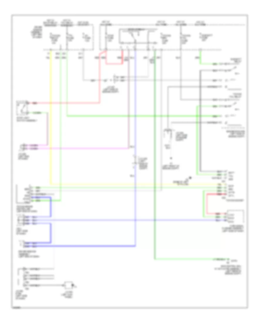
Backup Lamps Wiring Diagram for Toyota 4Runner Trail 2010
List of elements for Backup Lamps Wiring Diagram for Toyota 4Runner Trail 2010:
- 2.7l
- 4.0l
- A1 (left front of engine compt)
- A50
- A64
- A70
- A71
- Acc
- Acc fuse 7.5a
- Alt fuse 120a (2.7l) 140a (4.0l)
- B17
- B33
- B35
- B56
- B57
- B59
- B67
- Backup
- Bkup lp 2 relay (2.7l)
- Bkup lp fuse 10a
- Bkup relay
- C20
- C22
- C23
- C31
- C40
- C53
- D20
- D31
- Diode (backup) (2.7l) (right end of dash)
- Driver side r/b assembly (left end of dash)
- Ecu-ig1 fuse 10a
- Engine room j/b assembly (left side of engine compt)
- Engine room r/b assembly (left side of engine compt)
- Hot at all times
- Hot in on or acc
- Hot in on or start
- Ig1
- J/b 4 (left side of dash)
- J/b 5 (center of dash)
- J/c a36 (left end of dash)
- J/c a38 (2.7l: left side of luggage compt) (4.0l: left side of engine compt)
- J/c b48 (right side of dash)
- J/c b66 (right side of dash)
- J/c f64 (center left of dash)
- J/c o19 (base of left "c" pillar)
- Left rear combination light assembly
- O1 (left "b" pillar)
- Park/neutral position switch assembly (right side of transmission)
- Pnk
- Red
- Right rear combination light assembly
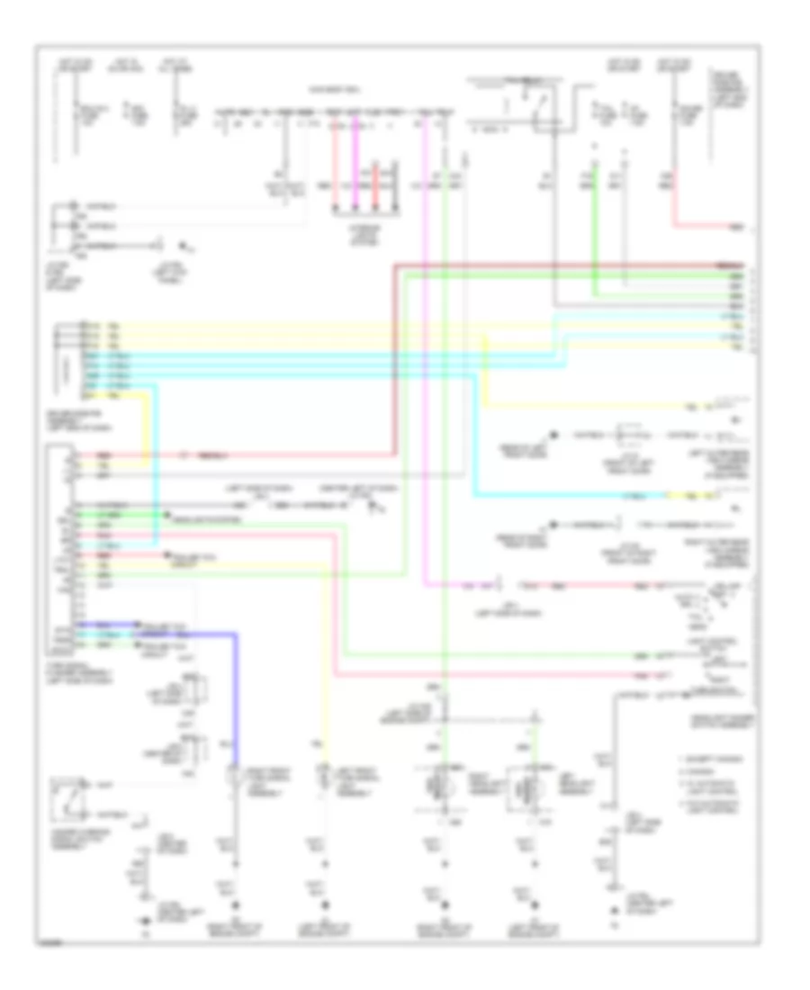
Exterior Lamps Wiring Diagram (1 of 2) for Toyota 4Runner Trail 2010
List of elements for Exterior Lamps Wiring Diagram (1 of 2) for Toyota 4Runner Trail 2010:
- (center left of dash) j/c f64
- (left side of dash) j/b 4
- A1 (left front of engine compt)
- A11
- A16
- A2 (right front of engine compt)
- A26
- A41
- A48
- A61
- A63
- A65
- Acc
- Acc fuse 7.5a
- Altb
- Auto drl
- B15
- B35
- B63
- B71
- C11
- C12
- C18
- C19
- C20
- C21
- C33
- C49
- C55
- Canada
- D/l 2 fuse 25a
- D11
- Driver side r/b assembly (left end of dash)
- Drl
- Drl-off off
- Ecu-ig 2 fuse 10a
- Except canada
- F10
- F14
- F15
- F16
- F27
- F55
- F56
- Flcy
- Frcy
- Gauge fuse 7.5a
- Gnd1
- Gnd2
- H1 (rear of right front door)
- Haz
- Hazard warning signal switch assembly
- Head
- Headlight dimmer switch assembly
- Headlights system
- Hot at all times
- Hot in on or acc
- Hot in on or start
- I1 (rear of left front door)
- Ig1 fuse 7.5a
- Interior lights system
- J/b 4 (left side of dash)
- J/b 5 (center of dash)
- J/c a40 (left side of engine compt)
- J/c f55 & f56 (left side of dash)
- J/c f63 (left kick panel)
- J/c f64 (center left of dash)
- J/c h8 (front of right front door)
- J/c i8 (front of left front door)
- Lcty
- Left
- Left front turn signal light assembly
- Left headlight assembly
- Left outer rear view mirror assembly (if equipped)
- Light control
- Light control switch
- Ltot
- Main body ecu
- Marker side
- Pnk
- Rcty
- Red
- Right
- Right front turn signal light assembly
- Right headlight assembly
- Right outer rear view mirror assembly (if equipped)
- Rtot
- Side marker
- Stin
- Tail
- Tail fuse 10a
- Tail relay
- Trailer tow circuit
- Trly
- Trnl
- Trnr
- Turn signal flasher assembly (left side of dash)
- Turn switch
- W/ automatic
- W/o automatic
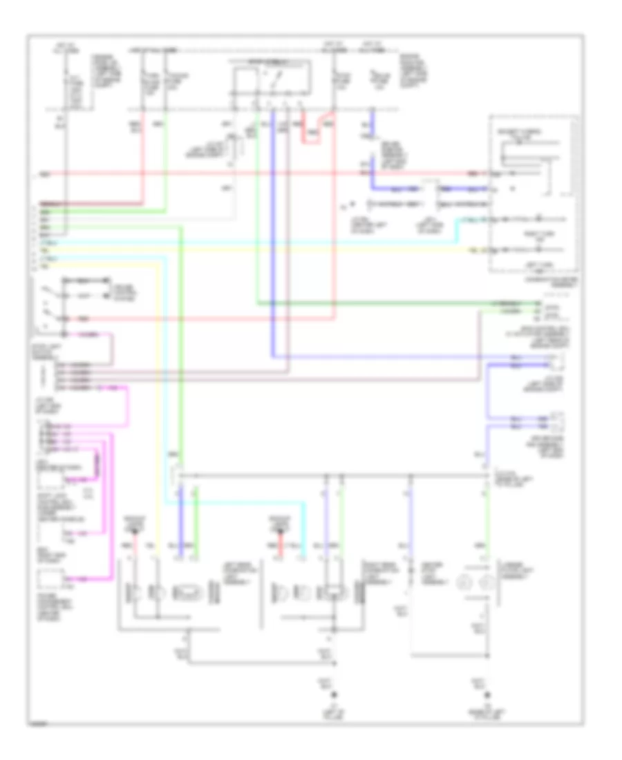
Exterior Lamps Wiring Diagram (2 of 2) for Toyota 4Runner Trail 2010
List of elements for Exterior Lamps Wiring Diagram (2 of 2) for Toyota 4Runner Trail 2010:
- (except hybrid) tail ind
- (or red)
- 2.7l 4.0l
- A16
- A68
- Alt fuse 120a (2.7l) 140a (4.0l)
- B14
- B22
- B63
- Backup
- Backup lamps circuit
- C51
- Center stop light assembly
- Combination meter assembly
- Cruise control system
- D35
- D39
- Driver side r/b assembly (left end of dash)
- Ecm (right end of dash)
- Ecu-b fuse 10a
- Engine room j/b assembly (left side of engine compt)
- Engine room r/b assembly (left side of engine compt)
- F29
- F50
- F81
- Hot at all times
- Ig+
- J/b 4 (left side of dash)
- J/b 5 (center of dash)
- J/c a36 (left end of dash)
- J/c a37 (left side of engine compt)
- J/c a39 (left side of engine compt)
- J/c f64 (center left of dash)
- J/c o19 (base of left "c" pillar)
- Left rear combination light assembly
- Left turn ind
- License plate light assembly
- Marker tail/side
- O1 (left "b" pillar)
- O2 (base of left "d" pillar)
- Power management control ecu (center of dash)
- Red
- Right rear combination light assembly
- Right turn ind
- Shift lock control ecu sub-assembly (under center console)
- Skid control ecu w/ actuator assembly (left rear of engine compt)
- Stop
- Stop fuse 10a
- Stop light switch assembly
- Stop lp relay
- Stp2
- Stpo
- Towing fuse 30a
- Turn
- Turn & haz fuse 15a
Trailer Tow Wiring Diagram for Toyota 4Runner Trail 2010
List of elements for Trailer Tow Wiring Diagram for Toyota 4Runner Trail 2010:
- A1 (left front of engine compt)
- A56
- A57
- A69
- B/up
- B32
- Batt
- Brk
- C49
- D11
- D21
- D35
- Driver side r/b assembly (left end of dash)
- Engine room r/b (left side of engine compt)
- F55
- F56
- Gnd
- Hot at all times
- Hot in on or start
- Hot w/ bk/up relay energized
- Hot w/ tail relay energized
- Ig1 fuse 7.5a
- J/b 4 (left side of dash)
- J/c a36 (left end of dash)
- J/c a37 (left side of engine compt)
- J/c a38 (left side of engine compt)
- J/c a39 (left side of engine compt)
- J/c f55 & f56 (left side of dash)
- J/c f63 (left kick panel)
- Ltot
- O2 (base of left "d" pillar)
- O21
- O22
- Red
- Rtot
- Skid control ecu w/ actuator assembly (left rear of engine compt)
- Stin
- Stop
- Stop fuse 10a
- Stop light switch assembly
- Stop lp relay
- Stpo
- Sttl
- Sttr
- Sub batt fuse 30a
- Sub batt relay
- Tail
- Tail fuse 10a
- Towing bk/up fuse 10a
- Towing brake controller (left end of dash)
- Towing brk fuse 30a
- Towing socket
- Towing tail fuse 30a
- Towing tail relay
- Turn signal flasher assembly (left side of dash)
GROUND DISTRIBUTION
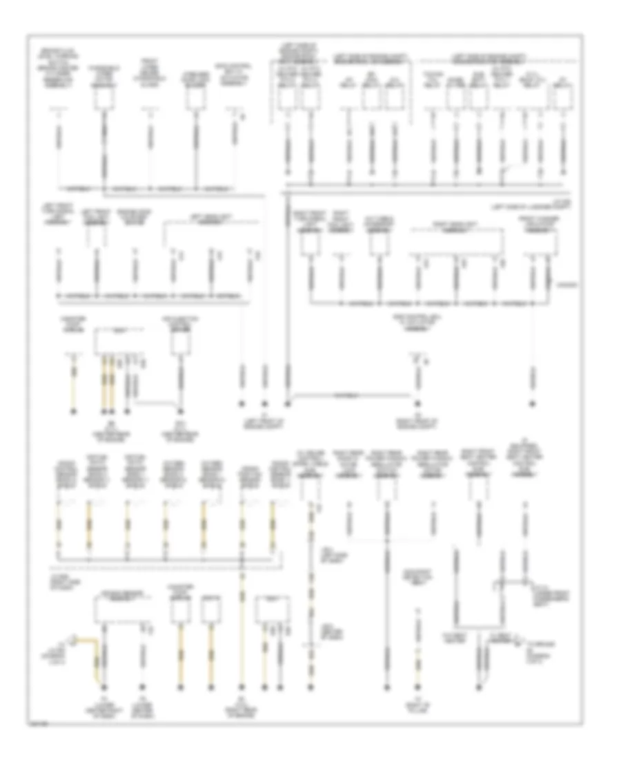
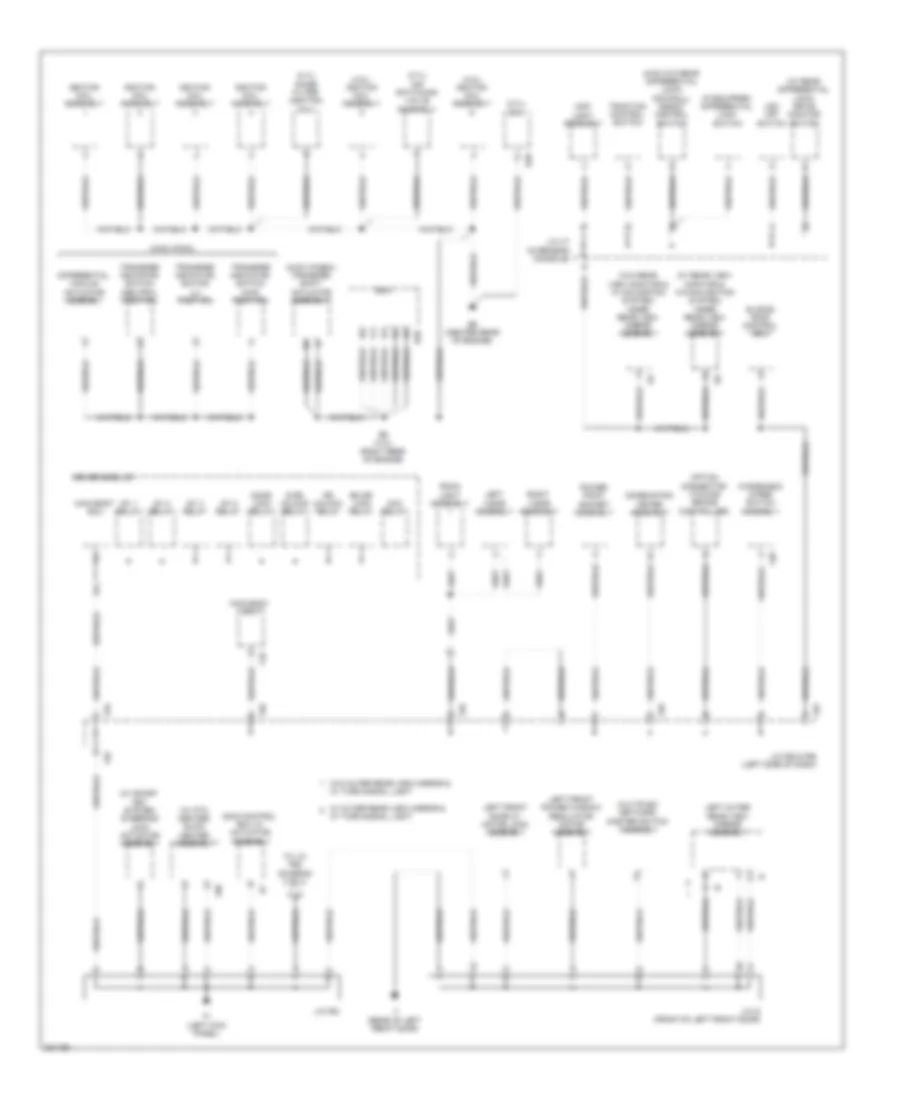
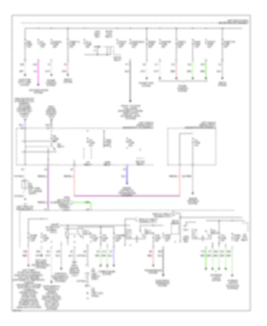
Ground Distribution Wiring Diagram (1 of 4) for Toyota 4Runner Trail 2010
List of elements for Ground Distribution Wiring Diagram (1 of 4) for Toyota 4Runner Trail 2010:
- (2.7l) bkup lp 2 relay
- (if equipped) right front seat heater control sub- assembly
- (left side of engine compt) engine room j/b assembly
- (left side of engine compt) engine room r/b 3 assembly
- (left side of engine compt) engine room r/b assembly
- (w/ cruise control) spiral cable sub- assembly
- (w/ ptc heater) ptc 1 relay
- (w/ ptc heater) ptc 2 relay
- (w/ ptc heater) ptc 3 relay
- A/c tube & accessory assembly
- A/f relay
- A1 (left front of engine compt)
- A14
- A15
- A16
- A2 (right front of engine compt)
- A24
- A25
- A26
- Air bag sensor assembly
- Air fuel ratio sensor (bank 1 sensor 1) shield
- Air fuel ratio sensor (bank 2 sensor 1) shield
- Air injection control driver
- B1 (4.0l) (right rear of engine)
- B10 (2.7l) (center rear of engine)
- B38
- B39
- B52
- B6 (2.7l) (center rear of engine)
- B64
- Brake fluid level warning switch (brake master cylinder reservoir assembly)
- C36
- C58
- Canada
- Canister pump module
- Crank position sensor shield
- Dlc 3
- Ecm
- Efi main relay
- Engine hood courtesy switch
- F to j/c f64 (diagram 4 of 4)
- F23
- F33
- F4 (lower center right of dash)
- F5 (lower center of dash)
- Front fog light assembly
- Front washer jar & pump assembly
- Front wiper deicer (windshield glass)
- Ig 2 relay
- J/b 4 (left side of dash)
- J/b 5 (center of dash)
- J/c a1 (under front passenger's seat)
- J/c a38 (left side of luggage compt)
- J/c b49 (right side of dash)
- Knock control sensor (bank 1) shield
- Knock control sensor (bank 2) shield
- Left front fog light assembly
- Left front turn signal light assembly
- Left headlight assembly
- N1 (right "b" pillar)
- Noise filter
- Occupant detection ecu
- Oxygen sensor (bank 1 sensor 2) shield
- Oxygen sensor (bank 2 sensor 2) shield
- Right
- Right front seat heater control sub- assembly
- Right front turn signal light assembly
- Right headlight assembly
- Right rear door w/ motor lock assembly
- Right rear power window regulator motor assembly
- Right rear power window regulator switch assembly
- Skid control ecu w/ actuator assembly
- St relay
- Sub batt relay
- To ground n2 (diagram 4 of 4)
- Towing tail relay
- W/ seat heater
- W/o seat heater
- Windshield wiper motor assembly
- Wireless door lock buzzer
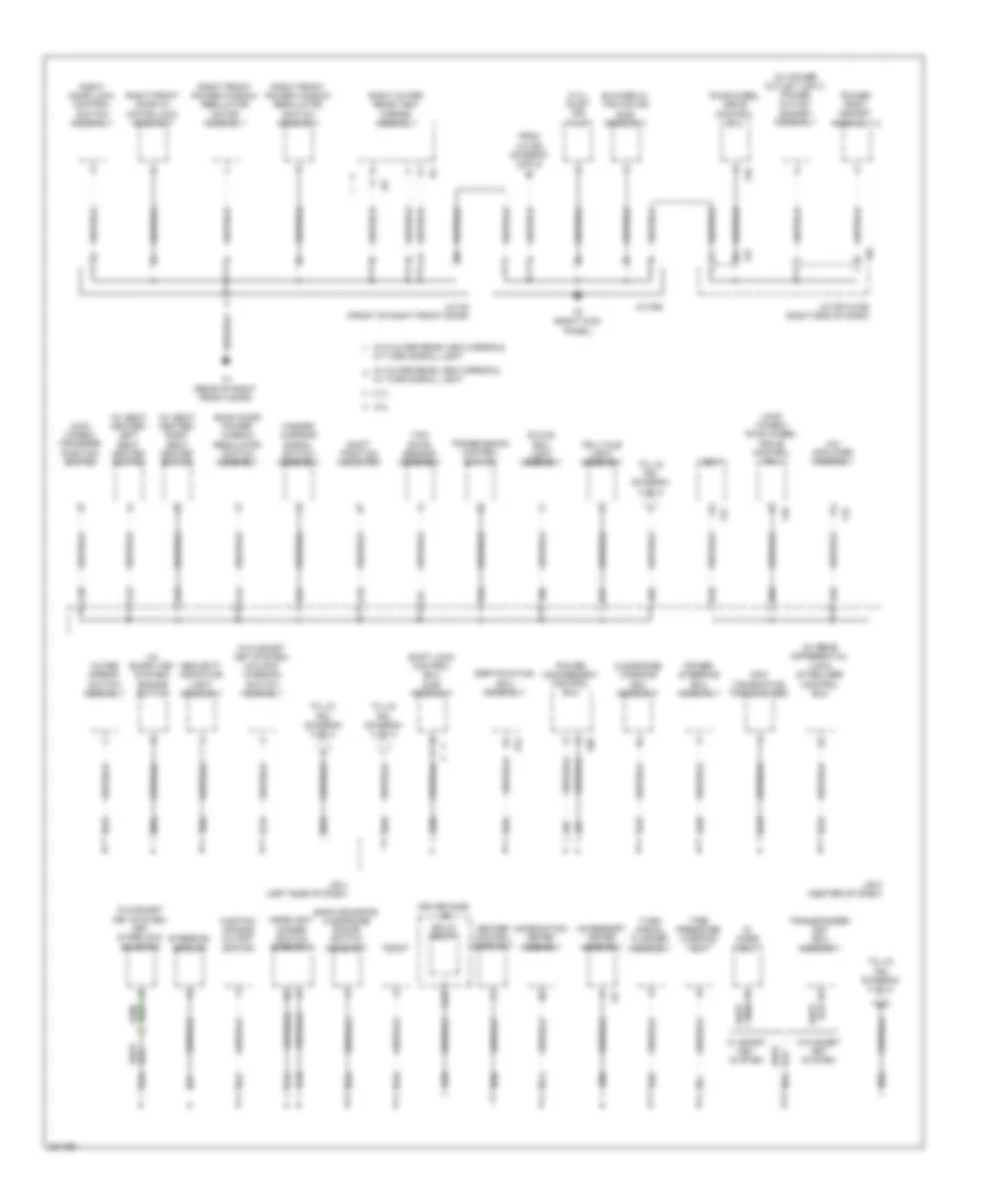
Ground Distribution Wiring Diagram (2 of 4) for Toyota 4Runner Trail 2010
List of elements for Ground Distribution Wiring Diagram (2 of 4) for Toyota 4Runner Trail 2010:
- (2.7l) air switching valve assembly
- (2.7l) ecm
- (2.7l) noise filter (ignition coil)
- (4.0l) ignition coil assembly
- (4wd (vf2a))
- (4wd (vf4bm)) transfer shift actuator assembly
- (4wd w/o rear differential lock) downhill assist control switch
- (if equipped) differential lock switch
- (w/ ptc heater) quick heater assembly
- (w/ rear differential lock) drive monitor switch
- (w/ rear view monitor & w/o navigation system) inner rear view mirror assembly
- (w/ smart key system) steering lock actuator assembly
- (w/o rear view monitor & w/ navigation system) inner rear view mirror assembly
- Acc relay
- B2 (4.0l) (right rear of engine)
- B39
- B9 (center rear of engine)
- Bk dr lock relay
- Combination meter assembly
- D-dr unlock relay
- Differential vacuum actuator assembly
- Door lock relay
- Dr unlock relay
- Driver side j/b
- Ecm
- F1 (left kick panel)
- F10
- F20
- F55
- F56
- F86
- I1 (rear of left front door)
- Ig1 1 relay
- Ig1 2 relay
- Ig1 3 relay
- Ig1 5 relay
- Ignition coil assembly
- J/c f55 & f56 (left side of dash)
- J/c f63
- J/c i8 (front of left front door)
- J/c u7 (overhead console)
- Left front door w/ motor lock assembly
- Left front power window regulator motor assembly
- Left outer rear view mirror assembly
- Left visor assembly
- Main body ecu
- Map light assembly
- Multiplex network master switch assembly
- Option connector (towing brake controller)
- Power point socket assembly
- Right visor assembly
- Room light assembly
- Skid control ecu w/ actuator assembly
- Sliding roof control ecu
- To j/c f65 (diagram 3 of 4)
- Traction control switch
- Transfer indicator switch (4wd position)
- Transfer indicator switch (l4 position)
- Transfer indicator switch (neutral position)
- Vsc off switch
- W/ outer rear view mirror &
- W/ turn signal light
- W/o outer rear view mirror &
- Windshield wiper switch assembly
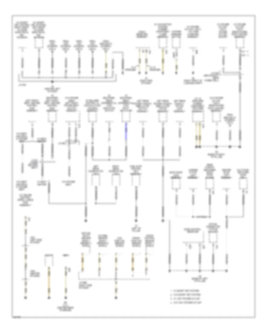
Ground Distribution Wiring Diagram (3 of 4) for Toyota 4Runner Trail 2010
List of elements for Ground Distribution Wiring Diagram (3 of 4) for Toyota 4Runner Trail 2010:
- (2.7l) inlet air pump
- (4wd (vf4bm)) four wheel drive control ecu
- (4wd (vf4bm)) transfer position switch
- (w/ power outlet (120v)) power outlet socket assembly
- (w/ rear differential lock) stabilizer control ecu
- (w/ seat heater) left seat heater switch
- (w/ seat heater) right seat heater switch
- (w/ smart key system) engine switch
- (w/o smart key system) key interlock solenoid
- (w/o smart key system) un-lock warning switch assembly
- 2.7l
- 4.0l
- A/c amplifier assembly
- A30
- A32
- A33
- A41
- A43
- A55
- A63
- A65
- A66
- A70
- A77
- A78
- A86
- A88
- Accessory meter assembly
- B10
- B14
- B33
- B34
- B35
- B47
- B50
- B59
- B60
- B62
- B63
- B69
- Back door power window regulator switch assembly
- Back sonar or clearance sonar switch assembly
- Bk/lp relay
- Blower w/ fan motor sub- assembly
- C10
- C11
- C22
- C30
- C32
- C33
- C34
- C42
- C43
- C44
- C54
- C60
- Certification ecu assembly
- Clearance warning ecu assembly
- Combination meter assembly
- Curtain air bag cutoff switch
- Dcm (telematics transceiver)
- Dlc3
- Driver side j/b
- Ecm
- F3 (right kick panel)
- F42
- F46
- F51
- F57
- F58
- F79
- F80
- Four wheel drive control ecu
- From j/c f63 (diagram 2 of 4)
- Glove box light assembly
- H1 (rear of right front door)
- Hazard warning signal switch assembly
- Headlight dimmer switch assembly
- Heater control assembly
- Id code box
- J/b 4 (left side of dash)
- J/b 5 (center of dash)
- J/c f57 & f58 (right end of dash)
- J/c f65
- J/c h8 (front of right front door)
- Outer mirror switch assembly
- Power management control ecu
- Power point socket assembly 2
- Power steering ecu assembly
- Right door lock control switch assembly
- Right front door w/ motor lock assembly
- Right front power window regulator motor assembly
- Right front power window regulator switch assembly
- Right outer rear view mirror assembly
- Security indicator light assembly
- Shift lock control ecu sub- assembly
- Shift position indicator
- Steering sensor
- Telltale light assembly
- Tire pressure warning ecu
- To j/c f64 (diagram 4 of 4)
- Transmission control switch
- Transponder key ecu assembly
- Turn signal flasher assembly
- W/ outer rear view mirror &
- W/ smart key system
- W/ turn signal light
- W/o outer rear view mirror &
- W/o smart key system
- Yaw rate sensor assembly
Ground Distribution Wiring Diagram (4 of 4) for Toyota 4Runner Trail 2010
List of elements for Ground Distribution Wiring Diagram (4 of 4) for Toyota 4Runner Trail 2010:
- (if equipped) left front seat heater control sub- assembly
- (if equipped) rear differential lock indicator switch
- (if equipped) rear differential lock shift actuator
- (w/ 15 speaker) stereo component amplifier assembly
- (w/ cruise control) spiral cable sub- assembly
- (w/ navigation system) stereo component tuner assembly
- (w/ power outlet (120v)) power outlet socket
- (w/ power outlet (120v)) rear power point socket assembly
- (w/ power outlet (120v)) voltage inverter assembly
- (w/ smart key system) left front outside electrical key antenna
- (w/ smart key system) right front outside electrical key antenna
- (w/o power outlet (120v)) rear power point socket assembly
- (w/o power seat) left front power seat switch assembly
- Air fuel ratio sensor (bank 1 sensor 1) shield
- B13
- B39
- B5 (2.7l) (center rear of engine)
- B52
- B64
- Back door lock assembly
- C36
- C58
- Cam position sensor shield
- Center stop light assembly
- Crank position sensor shield
- Dlc 3
- Door control receiver
- Ecm
- F2 (center left of dash)
- F23
- From ground f4 (diagram 1 of 4)
- From ground n1 (diagram 1 of 4)
- From j/b 4 (diagram 3 of 4)
- From j/b 5 (diagram 3 of 4)
- Fuel pump control ecu assembly
- G1 (right end of dash)
- G21
- G24
- J/b 4 (left side of dash)
- J/b 5 (center of dash)
- J/c b1 (under driver's seat)
- J/c b66 (right side of dash)
- J/c b8
- J/c f64
- J/c n22 (above right rear wheelwell)
- Knock control sensor (bank 1) shield
- Left front seat heater control sub- assembly
- Left rear combination light
- Left rear door w/ motor lock assembly
- Left rear power window regulator motor assembly
- Left rear power window regulator switch assembly
- License plate light assembly
- Multiplex network door ecu
- N14
- N16
- N17
- N2 (base of right "d" pillar)
- N20
- N3 (right front of luggage compt)
- O1 (left "b" pillar)
- O10
- O11
- O2 (base of left "d" pillar)
- O21
- Option connector (towing socket)
- Oxygen sensor (bank 1 sensor 2) shield
- Radio receiver assembly
- Rear window defogger (back door glass)
- Right rear combination light
- Stabilizer control w/ accumulator housing assembly
- W/ 120v power outlet
- W/ 15 speaker
- W/ 8 speaker
- W/ seat heater
- W/ smart key system
- W/o 120v power outlet
- W/o power seat
- W/o seat heater & w/ power seat
- W/o smart key system
- Woofer speaker switch
HEADLIGHTS
Headlights Wiring Diagram (1 of 2) for Toyota 4Runner Trail 2010
List of elements for Headlights Wiring Diagram (1 of 2) for Toyota 4Runner Trail 2010:
- (left kick panel) j/c f63
- (left side of dash) j/c f55 & f56
- A10
- A11
- Acc
- Acc fuse 7.5a
- Air conditioning
- Altb
- Auto drl
- Automatic light control sensor (if equipped) (top center of dash)
- B14
- B15
- B35
- Becu
- C10
- C11
- C12
- C37
- C55
- Canh
- Canl
- Cltb
- Clte
- Clts
- Computer data lines system
- D/l 2 fuse 25a
- D17
- D24
- D39
- D40
- Dim
- Dimmer switch
- Driver side r/b assembly (left end of dash)
- Drl
- Ecu-ig 2 fuse 10a
- Except usa
- F10
- F27
- F55
- F56
- Ffgo
- Ffog
- Flash
- Flcy
- Fog fr fuse 15a
- Fog switch
- Fr fog relay
- Frcy
- Gauge fuse 7.5a
- Gnd1
- Gnd2
- Head
- Headlight dimmer switch assembly
- High
- Hot at all times
- Hot in on or acc
- Hot in on or start
- Hot w/ tail relay energized
- Hrly
- Interior lights system
- J/b 4 (left side of dash)
- J/c f64 (center left of dash)
- Lcty
- Light control
- Light control switch
- Low
- Main body ecu
- Off drl off
- Parking brake switch assembly (upper left end of dash)
- Pkb
- Pnk
- Rcty
- Red
- System
- Tail
- Tail fuse 10a
- Tsl
- Tsr
- Usa
- W/ automatic
- W/o automatic
Headlights Wiring Diagram (2 of 2) for Toyota 4Runner Trail 2010
List of elements for Headlights Wiring Diagram (2 of 2) for Toyota 4Runner Trail 2010:
- A1 (left front of engine compt)
- A12
- A15
- A2 (right front of engine compt)
- A24
- A25
- A68
- B14
- B22
- B63
- Combination meter assembly
- Computer data lines system
- Drl
- Ecu-b fuse 10a
- Engine room r/b assembly (left side of engine compt)
- F55
- F56
- Fog ind front
- H-lp hi fuse 20a
- H-lp hi relay
- H-lp lh-hi fuse 10a
- H-lp lh-lo fuse 10a
- H-lp lo relay
- H-lp rh-hi fuse 10a
- H-lp rh-lo fuse 10a
- High
- Hot at all times
- Ind beam
- Ind head (usa)
- J/b 4 (left side of dash)
- J/c a40 (left side of engine compt)
- J/c f55 & f56 (left side of dash)
- J/c f63 (left kick panel)
- J/c f64 (center left of dash)
- Left front fog light assembly
- Left headlight assembly
- Low
- Pnk
- Red
- Right front fog light assembly
- Right headlight assembly
- Turn signal flasher assembly (left side of dash)
HORN
Horn Wiring Diagram for Toyota 4Runner Trail 2010
List of elements for Horn Wiring Diagram for Toyota 4Runner Trail 2010:
- B25
- D29
- Driver side r/b assembly (left end of dash)
- Engine room j/b assembly (left side of engine compt)
- F23
- High pitched horn assembly (center front of engine compt)
- Horn
- Horn fuse 10a
- Horn relay
- Horn switch
- Hot at all times
- Low pitched horn assembly (2.7l: left front of engine compt) (4.0l: center front of engine compt)
- Main body ecu
- Spiral cable sub-assembly (top of steering column)
- Steering pad switch assembly
- Switch assembly
- W/ smart key system
- W/ steering pad
- W/o steering pad
- Z11
INSTRUMENT CLUSTER
Instrument Cluster Wiring Diagram (1 of 2) for Toyota 4Runner Trail 2010
List of elements for Instrument Cluster Wiring Diagram (1 of 2) for Toyota 4Runner Trail 2010:
- (except usa)
- (usa)
- 4lo ind
- 4wd ind
- A-trac ind
- A/d
- A/t oil temp ind
- A/t p ind
- A1 (left front of engine compt)
- A68
- A90
- A92
- Abs ind
- Anti-lock brakes system
- Auto lsd ind
- B14
- B20
- B22
- B63
- Beam ind
- Blink
- Brake fluid level warning switch (brake master cylinder reservoir assembly) (on brake fluid reservoir)
- Brake ind
- Buzzer
- C16
- C55
- Canh
- Canl
- Center differential lock ind
- Charge ind
- Chg-
- Chk
- Combination meter assembly
- Computer data lines system
- Crawl ind
- Cruise ind
- D39
- Door ind
- Down hill assist control ind
- Driver side r/b assembly (left end of dash)
- Driver's seat belt ind
- Eco ind
- Ecu-b fuse 10a
- Engine controls system
- Engine oil pressure switch assembly (2.7l: left front of engine) (4.0l: right front of engine)
- Engine room r/b (left side of engine compt)
- Exterior lights system
- F55
- F56
- Front fog ind
- Fuel gauge
- Fuel ind
- Fuel sender gauge assembly
- Gauge fuse 7.5a
- Gnd
- Head ind tail ind
- Hot at all times
- Hot w/ ig2 relay energized
- Ig+
- Il2-
- Ill-
- Illumination ind
- Interior lights system
- J/b 4 (left side of dash)
- J/c f55 & f56 (left side of dash)
- J/c f63 (left kick panel)
- J/c f64 (center left of dash)
- Kdss ind
- Lbl
- Lcd
- Left turn ind
- Lint
- Maint reqd ind
- Malfunction ind lamp
- Mgnd
- Multi terrain select ind
- Oil pressure ind
- P/sb
- Pnk
- Power steering ind
- R/o
- Rear differential lock ind (if equipped)
- Red
- Rhig
- Right turn ind
- Rsca off ind
- Rx+
- Set ind
- Skid control ecu w/ actuator assembly (left rear of engine compt)
- Slip ind
- Smart key ind
- Spd
- Speedometer
- Srs ind
- Starting/charging system
- Tachometer
- Temperature gauge
- Tire
- Tire pressure ind
- Tire pressure warning ecu (right side of dash)
- Trac off ind
- Trc off ind
- Tx+
- Volt gauge
- Vsc off ind
- Warning system
- Warning systems
- Washer ind (canada)
- Wiper/washer system
- Wlvl
Instrument Cluster Wiring Diagram (2 of 2) for Toyota 4Runner Trail 2010
List of elements for Instrument Cluster Wiring Diagram (2 of 2) for Toyota 4Runner Trail 2010:
- A38
- A50
- A66
- A82
- A86
- A87
- A91
- A94
- Acc
- Acc fuse 7.5a
- Accessory meter assembly
- Altb
- B14
- B15
- B17
- B23
- B25
- B39
- B63
- Back door lock assembly (lower center of tailgate)
- Bdcy
- Bdr
- Canh
- Canl
- Computer data lines system
- Courtesy
- Ctye
- D/l 2 fuse 25a
- D17
- Dat2
- Data
- Dcm (telematics transceiver) (center right of dash)
- Door back fuse 30a
- Drive monitor switch
- Driver side r/b assembly (left end of dash)
- Ecm (right end of dash)
- Ecu ig 2 fuse 10a
- F11
- F27
- F51
- F80
- Flcy
- Frcy
- G14
- G18
- Hot at all times
- Hot w/ acc relay energized
- Hot w/ ig 1 relay energized
- Ig+
- Ill+
- Ill-
- Interior lights system
- J/b 4 (left side of dash)
- J/b 4 (w/ rear differential lock) (left side of dash)
- J/b 5 (center of dash)
- J/c f64 (center left of dash)
- J/c g13 & g14 (top left side of dash) g13
- J/c n22 (above right rear wheelwell)
- J/c o18 (base of left "c" pillar)
- Lcty
- Left front door courtesy light switch assembly
- Left rear door courtesy light switch assembly
- Lin
- Main body ecu
- Mpx1
- Multiplex network door ecu (lower center of liftgate)
- N11
- N19
- Navigation receiver assembly (w/ navigation) radio receiver assembly (w/o navigation) (center of dash)
- Parking brake switch assembly (upper left end of dash)
- Pkb
- Pnk
- Power management control ecu (center of dash)
- Rcty
- Red
- Right front door courtesy light switch assembly
- Right rear door courtesy light switch assembly
- Spd
- Spdp
- Stereo component amplifier assembly (right side of cargo area)
- Th+
- Voltage inverter assembly (w/ power outlet) (right side of cargo area)
- W/ navigation
- W/ safety connect
- W/ smart key system
- W/o navigation
- W/o rear differential lock
- W10
INTERIOR LIGHTS
Courtesy Lamps Wiring Diagram (1 of 2) for Toyota 4Runner Trail 2010
List of elements for Courtesy Lamps Wiring Diagram (1 of 2) for Toyota 4Runner Trail 2010:
- (left kick panel) j/c f63
- (rear of left front door) i1
- (w/ smart key system)
- A15
- A16
- A28
- A54
- A68
- A71
- A72
- A89
- A92
- A94
- A95
- Acc
- Altb
- B13
- B15
- B18
- B22
- B26
- B33
- B34
- B36
- B62
- C23
- C50
- Canh
- Canl
- Computer data lines system
- Cspt
- D/l 2 fuse 25a
- D33
- Diode (right rear door courtesy switch) (front of right rear wheelwell)
- Driver side r/b assembly (left end of dash)
- Ecu-ig 2 fuse 10a
- F10
- F24
- F27
- F32
- F36
- F55
- F56
- F57
- F58
- Flcl
- Flcy
- Foot light
- Frcl
- Frcy
- Fspt
- Fuse 7.5a
- Gnd1
- Gnd2
- H1 (rear of right front door)
- Hot at all times
- Hot in on or acc
- Hot in on or start
- Ile
- J/b 4 (left side of dash)
- J/b 5 (center of dash)
- J/c f55 & f56 (left side of dash)
- J/c f55 (left side of dash)
- J/c f57 & f58 (w/ outer rear view mirror & turn signal light) (right end of dash)
- J/c f63 (left kick panel)
- J/c h8 (front of right front door)
- J/c i8 (front of left front door)
- J/c n22 (above right rear wheelwell)
- Lcty
- Left front door courtesy light assembly (if equipped)
- Left front door handle illumination (interior illumination lamp assembly 1) (if equipped)
- Left front foot light (interior illumination light assembly 1)
- Left outer rear view view assembly (if equipped)
- Lin2
- Main body ecu (driver side j/b assembly)
- Mile
- Pnk
- Rcty
- Red
- Right front door courtesy light assembly (if equipped)
- Right front door handle illumination (interior illumination lamp assembly 1) (if equipped)
- Right front foot light (interior illumination light assembly 1)
- Right outer rear view view assembly (if equipped)
- Right rear door courtesy light assembly (w/ door courtesy light)
- Right rear door courtesy light switch assembly
- Right rear door handle illumination (interior illumination lamp assembly 2) (w/ door handle illumination)
- W/ door courtesy light
- W/ smart key system
Courtesy Lamps Wiring Diagram (2 of 2) for Toyota 4Runner Trail 2010
List of elements for Courtesy Lamps Wiring Diagram (2 of 2) for Toyota 4Runner Trail 2010:
- (base of left "c" pillar) j/c o18
- (center left of dash) (w/ smart key system) engine switch
- (center of dash) certification ecu assembly
- (front of left rear wheelwell) diode (left rear door courtesy switch)
- (w/ door handle illumination) left rear door handle illumination (interior illumination lamp assembly 2)
- A58
- A62
- A73
- A74
- A77
- A78
- B35
- B69
- Back door lock assembly (lower center of tailgate)
- Bdcy
- C13
- C29
- Canh
- Canl
- Computer data lines system
- Courtesy
- Cty
- Ctye
- Dome fuse 10a
- Door
- Engine room r/b (left side of engine compt)
- F79
- Gnd
- Hot at all times
- Ignition key cylinder light
- J/b 4 (left side of dash)
- J/c f55 (left side of dash)
- J/c f63 (left kick panel)
- J/c f64 (center left of dash)
- J/c o18 (w/ door courtesy light) (base of left "c" pillar)
- J/c u7 (overhead console)
- Left front door courtesy light switch assembly
- Left map light
- Left rear door courtesy light assembly (w/ door courtesy light)
- Left rear door courtesy light switch assembly
- Left spot light assembly
- Left vanity light assembly
- Left visor assembly
- Lglp
- Lgp2
- Map light assembly
- Mpx1
- Multiplex network door ecu (lower center of liftgate)
- O2 (base of left "d" pillar)
- Off
- Pnk
- Red
- Right front door courtesy light switch assembly
- Right map light
- Right spot light assembly
- Right vanity light assembly
- Right visor assembly
- Room light assembly 1
- Swil
- Transponder key amplifier (w/o smart key system) (right side of steering column)
- W10
Instrument Illumination Wiring Diagram (1 of 2) for Toyota 4Runner Trail 2010
List of elements for Instrument Illumination Wiring Diagram (1 of 2) for Toyota 4Runner Trail 2010:
- (2.7l) (4.0l)
- (center right of dash) (w/ safety connect) dcm (telematics transceiver)
- (left side of dash) j/c f55 & f56
- A11
- A42
- A44
- A45
- A65
- A77
- A82
- A88
- A93
- Acan
- Acc
- Acc fuse 7.5a
- Alt fuse 120a 140a
- Altb
- Auto
- B31
- B35
- B36
- B40
- C11
- C12
- C25
- C26
- C40
- C41
- C45
- C46
- C59
- Canh
- Canl
- Computer data lines system
- D/l 2 fuse 25a
- Driver side r/b assembly (left end of dash)
- Ecu-ig 2 fuse 10a
- Engine room j/b assembly (left side of engine compt)
- F10
- F39
- F55
- F56
- Glove box light assembly
- Gnd1
- Gnd2
- Hazard warning signal switch assembly
- Head
- Headlight dimmer switch assembly
- Hot at all times
- Hot in on or acc
- Hot in on or start
- Ill+
- Ill-
- J/b 4 (left side of dash)
- J/b 5 (center of dash)
- J/c f63 (left kick panel)
- J/c f64 (center left of dash)
- Left seat heater switch (if equipped)
- Light control switch
- Main body ecu (driver side j/b assembly)
- Off
- Panel fuse 7.5a
- Red
- Right seat heater switch (if equipped)
- Shift position indicator (2.7l)
- Shift position indicator (indicator light wire sub-assembly)
- Tail
- Tail relay
- Telltale light assembly
- Trly
Instrument Illumination Wiring Diagram (2 of 2) for Toyota 4Runner Trail 2010
List of elements for Instrument Illumination Wiring Diagram (2 of 2) for Toyota 4Runner Trail 2010:
- (center left of dash) engine switch
- (center left of dash) j/c f64
- (center of dash) certification ecu assembly
- (left side of dash) j/b 4
- (w/ rear differential lock) drive monitor switch
- 4wd & w/o rear differential lock
- A/d
- A51
- A75
- A81
- A88
- A93
- Accessory meter assembly
- B14
- B18
- B27
- B30
- B35
- B38
- B39
- B42
- B46
- B51
- B52
- B56
- B57
- B63
- B69
- Back sonar or clearance sonar switch assembly
- Built-in type amplifier
- C18
- C21
- C30
- C55
- Canh
- Canl
- Combination meter assembly
- Computer data lines system
- Curtain air bag cutoff switch
- Differential lock switch
- Downhill assist control switch
- Driver side r/b assembly (left end of dash)
- F23
- F79
- Front window deicer switch (outer mirror heater switch assembly) (if equipped)
- G13
- G14
- G16
- G21
- G28
- Gauge fuse 7.5a
- Heater control assembly
- Hot in on or start
- Ill+
- Ill-
- Illumination
- J/b 4 (left side of dash)
- J/c f64 (center left of dash)
- J/c g13 & g14 (top left side of dash)
- J/c u7 (overhead console)
- Light control rheostat
- Radio receiver assembly (w/o navigation) navigation receiver assembly (w/ navigation) (center of dash)
- Red
- Separate type amplifier w/ navigation
- Separate type amplifier w/o navigation
- Spiral cable sub assembly (top of steering column)
- Steering pad switch assembly
- Swg
- Swil
- Traction control switch (4wd)
- Vsc off switch
- W/ navigation
- W/ rear differential lock
- W/o navigation
- Woofer speaker switch
- Z11
NAVIGATION
Navigation Wiring Diagram (1 of 3) for Toyota 4Runner Trail 2010
List of elements for Navigation Wiring Diagram (1 of 3) for Toyota 4Runner Trail 2010:
- A50
- A64
- A66
- A87
- A90
- A91
- A95
- Acc
- Acc fuse 7.5a
- Agnd
- Ali
- Alo
- Ari
- Aro
- Asgn
- Au1
- Au2
- Auxi
- Auxo
- B17
- B20
- B24
- B33
- B35
- B39
- B57
- B59
- C20
- C23
- C31
- Canh
- Canl
- Cdl+
- Cdl-
- Cdr+
- Cdr-
- Combination meter assembly
- Computer data lines system
- Csld
- D17
- Driver room r/b assembly (left end of dash)
- Driver side r/b assembly (left end of dash)
- Eau
- Ecu ig 1 fuse 10a
- Ecu ig 2 fuse 10a
- Engine room r/b assembly (left side of engine compt)
- F23
- G13
- G14
- G16
- G17
- G18
- G19
- Gnd
- Hot at all times
- Hot w/ acc relay energized
- Hot w/ ig 1 relay energized
- Ivo+
- Ivo-
- J/b 4 (left side of dash)
- J/b 5 (center of dash)
- J/c b48 (right side of dash)
- J/c g13 & g14 (top left side of dash)
- Left steering switch
- Macc
- Map light assembly
- Mco+
- Mco-
- Mode
- Mute
- Navigation receiver assembly (center of dash)
- Nca
- Off hook
- On hook
- Park/neutral position switch (right side of transmission)
- Parking brake switch assembly (upper left end of dash)
- Pkb
- Pnk
- Rad 1 fuse 10a
- Red
- Rev
- Right steering switch
- Seek+
- Seek-
- Skid control ecu w/ actuator assembly (left rear of engine compt)
- Sld1
- Sns2
- Sp1
- Spd
- Spiral cable sub-assembly (top of steering column)
- Steering pad switch assembly
- Stereo jack adapter assembly 1 (w/o multimedia interface ecu)
- Sw1
- Sw2
- Swg
- Telephone microphone
- Tx1+
- Tx1-
- Txm+
- Txm-
- Txo+
- Txo-
- Voice
- Volume+
- Volume-
- Z11
Navigation Wiring Diagram (2 of 3) for Toyota 4Runner Trail 2010
List of elements for Navigation Wiring Diagram (2 of 3) for Toyota 4Runner Trail 2010:
- (rear end of center console) stereo component tuner assembly
- (right end of dash) g1
- (right end of dash) multi-media interface ecu
- Acc
- Antenna
- Atx+
- Atx-
- Ca+
- Canh
- Canl
- Cb+
- Cgnd
- Computer data lines system
- Connect
- Cv+
- Cv-
- Flo+
- Flo-
- Fro+
- Fro-
- G1 (right end of dash)
- G11
- G20
- G23
- G24
- G25
- G27
- G28
- Gnd
- Gps antenna
- Ill+
- Ill-
- Interior lights system
- Macc
- Min+
- Min-
- Mut1
- Mut2
- Mute
- Navigation receiver assembly (center of dash)
- Nca
- Pnk
- Rear television camera assembly (if equipped) (center of tailgate)
- Red
- Red w/o safety nca
- Sgnd
- Sld
- Sns2
- Stereo jack adapter assembly 2
- Tx+
- Tx-
- Tx1+
- Tx1-
- Tx2+
- Tx2-
- Txo+
- Txo-
- Udi+
- Udi-
- Udo+
- Udo-
- Uesg
- Ujsg
- Uli+
- Uli-
- Ulo+
- Ulo-
- Up1
- Upo
- Uri+
- Uri-
- Uro+
- Uro-
- Usd1
- Usd2
- W/ safety connect
- W/o safety connect
Navigation Wiring Diagram (3 of 3) for Toyota 4Runner Trail 2010
List of elements for Navigation Wiring Diagram (3 of 3) for Toyota 4Runner Trail 2010:
- (center right of dash) dcm (telematics transceiver)
- (or pnk)
- +b2
- Acc
- Amp fuse 30a
- Engine room r/b assembly (left side of engine compt)
- Fl+
- Fl-
- Fr+
- Fr-
- G1 (right end of dash)
- Gnd
- Gnd2
- Hot at all times
- Il+2
- Il-2
- Int+
- Int-
- Interior lights system
- Left front speaker assembly 1
- Left front speaker assembly 2
- Left rear speaker assembly 1
- Left rear speaker assembly 2
- Mci+
- Mci-
- Mco+
- Mco-
- Mcvd
- Mute
- N11
- N12
- N13
- N14
- N2 (base of right "d" pillar)
- Nca
- Pnk
- R-l+
- R-l-
- R-r+
- R-r-
- Red
- Right front speaker assembly 1
- Right front speaker assembly 2
- Right rear speaker assembly 1
- Right rear speaker assembly 2
- Rl+
- Rl-
- Rr+
- Rr-
- Sgnd
- Sld
- Spd
- Spi+
- Spi-
- Spo+
- Spo-
- Stereo component amplifier assembly (right side of cargo area)
- Sw+
- Sw-
- Tmut
- Twl+
- Twl-
- Twr+
- Twr-
- Tx+
- Tx-
- W/ box speaker assembly 1
- W/ safety connect
- W/o safety connect
- Wf-
- Wf1+
- Wf1-
- Wf2+
- Wf2-
- Woofer speaker switch
Parking Assistant Wiring Diagram for Toyota 4Runner Trail 2010
List of elements for Parking Assistant Wiring Diagram for Toyota 4Runner Trail 2010:
- 2.7l
- 4.0l
- A51
- A64
- A66
- A78
- A80
- A81
- B31
- B34
- B35
- B36
- B39
- B40
- B48
- B53
- B54
- B57
- B59
- B66
- Back sonar or clearance sonar switch assembly
- Bbz
- C18
- C20
- C31
- Clearance sonar indicator
- Clearance warning buzzer 1 (center left of dash)
- Clearance warning ecu assembly (top left side of dash)
- Clsw
- Diode (backup light) (2.7l) (right end of dash)
- Driver side r/b assembly (left end of dash)
- Ecu
- Ecu ig 1 fuse 10a
- Ecu ig 2 fuse 10a
- Hot w/ ig 1 relay energized
- Hot w/ tail relay energized
- Ig1
- Ill+
- Ill-
- Ind
- Interior lights system
- J/b 4 (left side of dash)
- J/b 5 (center of dash)
- J/c b48 & b66 (right side of dash)
- J/c f64 (center left of dash)
- L10
- Left ultrasonic sensor 1 (center left of rear bumper)
- Left ultrasonic sensor 2 (left end of rear bumper)
- Main body ecu
- Panel fuse 7.5a
- Park/neutral position switch (right side of transmission)
- Pnk
- Red
- Right ultrasonic sensor 1 (center right of rear bumper)
- Right ultrasonic sensor 2 (right end of rear bumper)
- Security indicator light assembly
- Sonar switch
Rear View Camera Wiring Diagram for Toyota 4Runner Trail 2010
List of elements for Rear View Camera Wiring Diagram for Toyota 4Runner Trail 2010:
- A64
- A66
- A79
- A83
- B33
- B35
- B39
- B57 red
- B59
- C20
- C23
- C31
- Cb+
- Cgkd
- Cgnd
- Cv+
- Cv-
- Driver side r/b assembly (left end of dash)
- Ecu-ig 1 fuse 10a
- Ecu-ig 2 fuse 10a
- F55
- F56
- Hot w/ ig1 relay energized
- Inner rear view mirror assembly
- J/b 4 (left side of dash)
- J/b 5 (center of dash)
- J/c b48 (right side of dash)
- J/c f55 & f56 (left side of dash)
- J/c f63 (left kick panel)
- Nca
- Park/neutral position switch (right side of transmission)
- Rear television camera assembly (center of tailgate)
- Red
- Rev
Telematics Wiring Diagram for Toyota 4Runner Trail 2010
List of elements for Telematics Wiring Diagram for Toyota 4Runner Trail 2010:
- (or pnk)
- A37
- A43
- A44
- A46
- A49
- A50
- A51
- A66
- Acc
- Acc fuse 7.5a
- Air bag sensor assembly (below center of dash)
- B17
- B27
- B36
- B40
- B67
- Backup battery (mayday battery) (right side of dash)
- Bbi+
- Bbi-
- Bbo+
- Bbo-
- Btr1
- Btr2
- Built-in type amplifier
- C15
- C18
- C50
- C51
- C53
- Computer data lines system
- Ctr1
- Ctr2
- Dcm (telematics transceiver) (center right of dash)
- Driver side r/b assembly (left end of dash)
- Engine room r/b assembly (left side of engine compt)
- F33
- Fr+
- Fr-
- G20
- Gnd
- Gps antenna
- Gsw
- Gsw3
- Hot at all times
- Hot w/ acc relay energized
- Hot w/ ig2 relay energized
- Hot w/ tail relay energized
- Ig2
- Ign fuse 10a
- Ill+
- Ind1
- Ind2
- Instrument cluster system
- J/b 4 (left side of dash)
- J/b 5 (center of dash)
- J/c f64 (center left of dash)
- Macc
- Map light assembly
- Mayday fuse 7.5a
- Mci+
- Mci-
- Mco+
- Mco-
- Mcvd
- Min+
- Min-
- Mute
- N11
- N12
- Navigation receiver assembly (w/ navigation) (center of dash) radio receiver assembly (w/o navigation)
- Nca
- Panel fuse 7.5a
- Pnk
- Red
- Right front speaker assembly 1
- Right front speaker assembly 2
- Rrid
- Separate type amplifier
- Sgnd
- Sig-
- Sig1
- Sig2
- Sil
- Sled
- Sos switch
- Spdp
- Spi+
- Spi-
- Spo+
- Spo-
- Stereo component amplifier assembly (right side of cargo area)
- Telephone antenna
- Tmut
- Twr+
- Twr-
- W/ navigation
- W/o navigation
POWER DISTRIBUTION
Power Distribution Wiring Diagram (1 of 4) for Toyota 4Runner Trail 2010
List of elements for Power Distribution Wiring Diagram (1 of 4) for Toyota 4Runner Trail 2010:
- (2.7l)
- (4.0l)
- (left side of engine compartment) engine room r/b assembly
- A/c comp fuse 10a
- Abs 1 fuse 50a
- Abs 2 fuse 30a
- Air conditioning system
- Air pmp fuse 50a
- Alt fuse 120a 140a
- Alt-s fuse 7.5a
- Am2 fuse 7.5a
- Amp fuse 30a
- Anti-lock brakes system
- Anti-lock brakes, shift interlock & cruise control systems
- Anti-theft system
- Battery
- Def fuse 30a
- Defogger system
- Deicer fuse 20a
- Dome fuse 10a
- Door locks & anti-theft systems
- Door locks, instrument cluster, wiper/washer, trunk, tailgate, fuel doors, headlights, interior lights, exterior lights, shift interlock, anti-theft, starting/charging & power windows systems
- Ecu-b fuse 10a
- Engine controls system
- Engine room j/b assembly (left side of engine compt)
- Etcs fuse 10a
- Exterior lights system
- H-lp hi fuse 20a
- H-lp hi relay
- H-lp lo relay
- Htr fuse 50a
- Inv fuse 80a
- Key system
- Mayday fuse 7.5a
- Mir htr fuse 10a
- Navigation & sound systems
- Navigation system
- P/i-b fuse 80a
- Pnk
- Ptc htr 1 fuse 50a
- Ptc htr 2 fuse 30a
- Ptc htr 3 fuse 30a
- Rad 1 fuse 10a
- Red
- Security fuse 10a
- Shift interlock system
- Short pin
- Smart fuse 7.5a
- Sound systems
- St fuse 30a
- Starting/ charging system
- Stop fuse 10a
- Strg lock fuse 20a
- Sub batt fuse 30a
- To driver side j/b (diagram 3 of 4)
- To engine room j/b (diagram 3 of 4)
- To engine room r/b 3 (diagram 4 of 4)
- To ignition or starter switch assembly (diagram 2 of 4)
- To j/b 5 (diagram 2 of 4)
- Towing brk fuse 30a
- Towing fuse 30a
- Towing tail fuse 30a
- Turn & haz fuse 15a
- W/ smart
- W/o smart key system
Power Distribution Wiring Diagram (2 of 4) for Toyota 4Runner Trail 2010
List of elements for Power Distribution Wiring Diagram (2 of 4) for Toyota 4Runner Trail 2010:
- (center of dash) j/b 5
- A19
- Acc
- Acc fuse 7.5a
- Acc relay
- Accd
- Air conditioning, anti-lock brakes, exterior lights & starting/ charging systems
- Am1
- Am2
- Am21
- Am22
- B17
- B35
- B39
- B69
- C14
- C31
- C33
- C48
- C52
- D11
- D27
- D31
- Defogger system
- Driver side r/b assembly (left end of dash)
- Ecu-ig 1 fuse 10a
- Ecu-ig 2 fuse 10a
- Engine switch (w/ smart key system)
- Exterior lights system
- Exterior lights, anti-lock brakes & defogger systems
- F30
- F55
- F56
- F57
- F58
- F80
- F81
- From engine room r/b (diagram 1 of 4)
- From st fuse (diagram 1 of 4)
- Ig 1 relay
- Ig1
- Ig1 5 relay
- Ig1 fuse 7.5a
- Ig1d
- Ig2
- Ig2d
- Ignition or starter switch assembly (w/o smart key system)
- Instrument cluster, exterior lights, starting/ charging, headlights, anti-theft, trunk, tailgate, fuel doors, door locks, shift interlock, interior lights, wiper/ washer & power windows systems
- J/b 4 (left side of dash)
- J/c a37 (left side of luggage compt)
- J/c f55 & f56 (left side of dash)
- J/c f56 (left side of dash)
- J/c f57 & f58 (right end of dash)
- J/c f63 (left kick panel)
- J/c f64 (center left of dash)
- J/c f65 (right kick panel)
- J/c n22 (w/ 120v power outlet) (above right rear wheelwell)
- Lock
- Main body ecu
- Mirrors, navigation, shift interlock, exterior lights, instrument cluster, anti-lock brakes, sound & door locks systems
- N16
- N17
- N2 (base of right "d" pillar)
- Off
- P/outlet fuse 15a
- Pnk
- Power management control ecu (w/ smart key system) (center of dash)
- Power point socket assembly
- Power point socket assembly 2
- Rear power point socket assembly
- Red
- S/htr fr fuse 20a
- Seats system
- Ssw1
- Ssw2
- St1
- St2
- Start
- Starting/ charging system
- To driver side j/b (diagram 3 of 4)
- To engine room j/b (diagram 3 of 4)
- To engine room r/b 3 (diagram 4 of 4)
- To ig1 2 relay (diagram 3 of 4)
- To ig1 3 relay (diagram 3 of 4)
- To j/b 4 (diagram 4 of 4)
- Transmissions, exterior lights, anti-lock brakes, instrument cluster, headlights, shift interlock, navigation, cruise control, sound, door locks, electronic power steering, warning & electronic suspension systems
- W/ 120v power outlet
- W/ smart key system
- W/o 120v power outlet
- W/o smart key system
- Wiper/ washer system
Power Distribution Wiring Diagram (3 of 4) for Toyota 4Runner Trail 2010
List of elements for Power Distribution Wiring Diagram (3 of 4) for Toyota 4Runner Trail 2010:
- (left end of dash) driver side r/b assembly
- (left side of engine compt) engine room j/b assembly
- (left side of engine compt) engine room r/b assembly
- 4wd fuse 20a
- A/c fuse 7.5a
- A/f fuse 20a
- A/f relay
- A1 (left front of engine compt)
- Air conditioning system
- Altb
- Am1 fuse 7.5a
- Anti-lock brakes & cruise control systems
- B10
- B20
- B32
- B40
- Bk dr lock relay
- Bk/up relay
- C11
- C12
- C13
- C26
- C29
- C34
- C35
- C38
- C51
- C55
- Computer data lines system
- D/l 2 fuse 25a
- D21
- D26
- Door back fuse 30a
- Door d fuse 25a
- Door fuse 7.5a
- Door p fuse 30a
- Door rl fuse 25a
- Door rr fuse 25a
- Efi fuse 25a
- Efi main relay
- Electronic suspension system
- Engine controls & transmissions systems
- Engine controls system
- Exterior lights system
- F11
- F16
- Fog fr fuse 15a
- Fr fog relay
- From engine room j/b (diagram 1 of 4)
- From engine room r/b (diagram 1 of 4)
- From h ig1 relay (diagram 2 of 4)
- From ig1 5 relay (diagram 2 of 4)
- From ig1 5 relay j (diagram 2 of 4)
- From ignition or starter switch assembly or power management control ecu (diagram 2 of 4)
- From ignition or starter switch f assembly (diagram 2 of 4)
- Gauge fuse 7.5a
- Horn fuse 10a
- Horn relay
- Ig1 2 relay
- Ig1 3 relay
- Ig2 fuse 20a
- Ig2 relay
- Ign fuse 10a
- Inj fuse 10a
- Interior lights & navigation systems
- J/c a38 (left side of luggage compt)
- J/c f55 (left side of dash)
- J/c f63 (left kick panel)
- Kdss fuse 10a
- Main body ecu
- Obd fuse 7.5a
- P/seat fl fuse 30a
- P/seat fr fuse 30a
- Panel fuse 7.5a
- Pnk
- Power tops system
- Power windows system
- Red
- S/roof fuse 25a
- Seats system
- Tail fuse 10a
- Tail relay
- Transmissions system
- Trly
- Trunk, tailgate, fuel doors, instrument cluster, headlights & exterior lights systems
- Washer fuse 20a
- Wip fuse 30a
- Wiper/washer system
Power Distribution Wiring Diagram (4 of 4) for Toyota 4Runner Trail 2010
List of elements for Power Distribution Wiring Diagram (4 of 4) for Toyota 4Runner Trail 2010:
- (diagram 1 of 4)
- 100w
- 400w
- A/c 120v
- A13
- A38
- A66
- A67
- A79
- A91
- Ac1
- Ac2
- Acc1
- Acc2
- Acc3
- Acc4
- Air conditioning & seats systems
- Air conditioning system
- B14
- B17
- B20
- B21
- B25
- B31
- B37
- B41
- B43
- B44
- B53
- B55
- C16
- C19
- Combination meter assembly
- Defogger & navigation systems
- Diode (voltage inverter) (right end of dash)
- Ecm (right end of dash)
- Els2
- Engine room r/b 3 assembly (left side of engine compt)
- Excd
- F51
- F57
- F58
- From driver side j/b (diagram 2 of 4)
- From engine room r/b a
- From j/c a37 l (diagram 2 of 4)
- Gnd
- Ind
- Ind+
- Ind-
- Instrument cluster system
- Inv relay (400w)
- J/b (center of dash)
- J/b (left side of dash)
- J/b 4 (left side of dash)
- J/b 5 (center of dash)
- J/c f57 & f58 (right end of dash)
- J/c f65 (right kick panel)
- J/c n22 (above right rear wheelwell)
- Main switch assembly
- Mirrors & power tops systems
- N19
- N2 (base of right "d" pillar)
- N20
- N3 (right front of luggage compt)
- Navigation & power tops systems
- Navigation system
- Nsw
- Pnk
- Power outlet socket
- Power outlet socket assembly
- Red
- Rly
- Skid control ecu w/ actuator assembly (left rear of engine compt)
- Sound & navigation systems
- Sp1
- Spd
- Starting/charging system
- Voltage inverter assembly
- W/ smart key system
- W/o smart key system
POWER DOOR LOCKS
Power Door Locks Wiring Diagram, with Smart Key System (1 of 5) for Toyota 4Runner Trail 2010
List of elements for Power Door Locks Wiring Diagram, with Smart Key System (1 of 5) for Toyota 4Runner Trail 2010:
- (base of left "d" pillar) o2
- A19
- A20
- A21
- A24
- A60
- Acc
- Acc fuse 7.5a
- Act+
- Act-
- Actd
- Altb
- B11
- B14
- B15
- B18
- B29
- B34
- Back door lock assembly (lower center of tailgate)
- Becu
- Bk dr lock relay
- Canh
- Canl
- Computer data lines system
- Courtesy
- D-dr unlock relay
- D/l 2 fuse 25a
- D23
- D24
- D25
- D29
- D39
- D40
- Dash)
- Dim
- Door lock control switch
- Door lock relay
- Dr unlock relay
- Driver side r/b assembly (left end of dash)
- Ecu-ig 2 fuse 10a
- Exterior lights system
- F10
- F19
- F24
- F25
- F27
- F55
- F56
- F58
- Flcy
- Frcy
- Gnd1
- Gnd2
- H1 (rear of right front door)
- Haz
- Hcty
- Headlights system
- Horn
- Hot at all times
- Hot in on or acc
- Hot in on or start
- Hrly
- Ile
- Ind
- Interior lights system
- J/b 4 (left side of dash)
- J/c f55 & f56 (left side of f55
- J/c f55 & f56 (left side of f56
- J/c f57 & f58 (right end of f57
- J/c f63 (left kick panel)
- J/c h8 (front of right front door)
- J/c n22 (above right rear wheelwell)
- J/c o18 (base of left "c" pillar)
- Lcty
- Left front door courtesy light switch assembly
- Left rear door courtesy light switch assembly
- Lin1
- Lin2
- Lock
- Lsfl
- Lsfr
- Lswl
- Lswr
- Main body ecu (driver side j/b assembly)
- Multiplex network master switch assembly (left front door)
- Pnk
- Rcty
- Red
- Right door control switch assembly
- Right front door courtesy light switch assembly
- Right rear door courtesy light switch assembly
- Tr+
- Trly
- Ul1
- Ul3
- Unlock
Power Door Locks Wiring Diagram, with Smart Key System (2 of 5) for Toyota 4Runner Trail 2010
List of elements for Power Door Locks Wiring Diagram, with Smart Key System (2 of 5) for Toyota 4Runner Trail 2010:
- (2.7l: left front of engine compt) (4.0l: center front of engine compt) low pitched horn assembly
- (left "b" pillar) o1
- (lower center of liftgate) multiplex network door ecu
- (rear of left front door)
- (rear of right front door)
- (right "b" pillar) n1
- Back door opener switch
- Bdcy
- Bdr
- Becu
- C31
- Ctye
- D33
- Dome fuse 10a
- Door back fuse 30a
- Driver side r/b assembly (left end of dash)
- Ecu-b fuse 10a
- Ecu-ig fuse 10a
- Engine room j/b assembly (left side of engine compt)
- Engine room r/b assembly (left side of engine compt)
- F11
- F30
- F32
- F57
- F58
- Gnd
- High pitched horn assembly (center front of engine compt)
- Horn fuse 10a
- Horn relay
- Hot at all times
- Hot in on or start
- Hsw+
- Hsw-
- Hswz
- Interior lights system
- J/c f57 & f58 (right end of dash)
- J/c h8 (front of right front door)
- J/c i8 (front of left front door)
- J/c o18 (base of left "c" pillar)
- Left front door w/ motor lock assembly (left front door)
- Left rear door w/
- License plate light assembly
- Lock
- Lock key
- Motor lock assembly (left rear door)
- Motor lock assembly (right rear door)
- Mpx1
- O2 (base of left "d" pillar)
- Pnk
- Red
- Right front door w/ motor lock assembly (right front door)
- Right rear door w/
- Sig
- Sup2
- Tion detec- unlock
- Un- key
- W10
Power Door Locks Wiring Diagram, with Smart Key System (3 of 5) for Toyota 4Runner Trail 2010
List of elements for Power Door Locks Wiring Diagram, with Smart Key System (3 of 5) for Toyota 4Runner Trail 2010:
- (center left of dash) engine switch
- (left rear of engine compt)
- (right end of dash)
- A12
- A16
- A59
- A64
- A66
- Accd
- Am21
- Am22
- Antenna coil
- Assembly
- B20
- B25
- B35
- B36
- B37
- B59
- B62
- B63
- B69
- C16
- C20
- C56
- Ca1h
- Ca1l
- Ca3n
- Ca3p
- Canh
- Canl
- Computer data lines system
- Ecm
- Engine room r/b assembly (left side of engine compt)
- F50
- F80
- F81
- Gnd
- Gnd2
- Hot at all times
- Ig1d
- Ig2d
- Imi
- Imo
- Inds
- Indw
- J/b 4 (left side of dash)
- J/b 5 (center of dash)
- J/c a36 (left end of dash)
- J/c f64 (center left of dash)
- Lin2
- Neo
- Park/neutral position switch (right side of transmission)
- Pnk
- Power distribution system
- Power management control ecu (center of dash)
- Red
- Shift interlock system
- Shift lock control ecu sub-assembly (under center console)
- Skid control ecu w/ actuator
- Slp
- Slr+
- Sp1
- Spd
- Ss1
- Ss2
- Ssw1
- Ssw2
- Sta
- Star
- Starting/ charging system
- Stop fuse 10a
- Stop light switch assembly
- Stp1
Power Door Locks Wiring Diagram, with Smart Key System (4 of 5) for Toyota 4Runner Trail 2010
List of elements for Power Door Locks Wiring Diagram, with Smart Key System (4 of 5) for Toyota 4Runner Trail 2010:
- (center left of dash) id code box
- (center of dash) j/b 5
- (left front of engine compt) a1
- (left side of dash) j/b 4
- A48
- A49
- A53
- A57
- A68
- B14
- B22
- B27
- B30
- B63
- B68
- B71
- Buzzer
- C17
- C45
- C51
- C55
- C57
- C60
- Combination meter assembly
- Computer data lines system
- Door ind
- Driver side r/b assembly (left end of dash)
- Efii
- Efio
- Engine hood courtesy switch (center front of engine compt)
- Engine room r/b assembly (left side of engine compt)
- Gauge fuse 7.5a
- Gnd
- Hot at all times
- Hot in on or start
- Ign fuse 10a
- Ind
- J/b 4 (left side of dash)
- J/c f64 (center left of dash)
- Lin1
- Pnk
- Red
- S-horn relay
- Security fuse 10a
- Security horn assembly (right front of engine compt)
- Smart fuse 7.5a
- Smart key
Power Door Locks Wiring Diagram, with Smart Key System (5 of 5) for Toyota 4Runner Trail 2010
List of elements for Power Door Locks Wiring Diagram, with Smart Key System (5 of 5) for Toyota 4Runner Trail 2010:
- (base of left "c" pillar)
- (center console) front indoor electrical key antenna assembly
- (center of dash) j/b 5
- (center of luggage compt)
- A50
- A51
- A52
- A55
- A60
- A62
- A63
- A64
- A66
- A69
- Agnd
- Ant1
- Ant2
- B35
- B59
- Canh
- Canl
- Certification ecu assembly (center side of dash)
- Cg1b
- Cg2b
- Cg5b
- Cg6b
- Cg7b
- Cg8b
- Clg1
- Clg2
- Clg5
- Clg6
- Clg7
- Clg8
- Clgb
- Code
- Computer data lines system
- Cutb
- Data
- Door control receiver (rear of left "c" pillar)
- F78
- F79
- Gnd
- Ind
- Indoor luggage compartment electrical key antenna assembly
- J/b 4 (left side of dash)
- J/c f64 (center left of dash)
- Left front outside electrical key antenna
- Lin
- O2 (base of left "d" pillar)
- Outside luggage electrical key antenna (center rear of luggage compt)
- Pnk
- Pos1
- Pos2
- Rco
- Rda
- Rear indoor electrical key antenna assembly
- Red
- Right front outside electrical key antenna (top rear of right front door)
- Rssi
- Security indicator light assembly
- Sen1
- Sen2
- Sens
- Swil
- Trg+
- Tsw1
- Tsw2
- Tsw5
- Tsw6
- Txct
- Vc5
Power Door Locks Wiring Diagram, without Smart Key System (1 of 3) for Toyota 4Runner Trail 2010
List of elements for Power Door Locks Wiring Diagram, without Smart Key System (1 of 3) for Toyota 4Runner Trail 2010:
- (base of left "d" pillar) o2
- A19
- A20
- A21
- A24
- A60
- Acc
- Acc fuse 7.5a
- Act+
- Act-
- Actd
- Altb
- B11
- B15
- B17
- B18
- B33
- B34
- Back door lock assembly (lower center of tailgate)
- Becu
- Bk dr lock relay
- Bzr
- Canh
- Canl
- Computer data lines system
- Courtesy
- D-dr unlock relay
- D/l 2 fuse 25a
- D13
- D23
- D24
- D25
- D29
- D39
- D40
- Dash)
- Dim
- Door lock control switch
- Door lock relay
- Dr unlock relay
- Driver side r/b assembly (left end of dash)
- Ecu-ig 2 fuse 10a
- Exterior lights system
- F10
- F19
- F24
- F25
- F27
- F55
- F56
- F58
- Flcy
- Frcy
- Gnd1
- Gnd2
- H1 (rear of right front door)
- Haz
- Hcty
- Headlights system
- Horn
- Hot at all times
- Hot in on or acc
- Hot in on or start
- Hrly
- Ile
- Ind
- Interior lights system
- J/b 4 (left side of dash)
- J/c f55 & f56 (left side of f55
- J/c f55 & f56 (left side of f56
- J/c f57 & f58 (right end of f57
- J/c f63 (left kick panel)
- J/c h8 (front of right front door)
- J/c n22 (above right rear wheelwell)
- J/c o18 (base of left "c" pillar)
- Ksw
- Lcty
- Left front door courtesy light switch assembly
- Left rear door courtesy light switch assembly
- Lin1
- Lin2
- Lock
- Lsfl
- Lsfr
- Lswl
- Lswr
- Main body ecu (driver side j/b assembly)
- Multiplex network master switch assembly (left front door)
- Pnk
- Prg
- Rcty
- Rda
- Red
- Right door control switch assembly
- Right front door courtesy light switch assembly
- Right rear door courtesy light switch assembly
- Tr+
- Trly
- Ul1
- Ul3
- Unlock
Power Door Locks Wiring Diagram, without Smart Key System (2 of 3) for Toyota 4Runner Trail 2010
List of elements for Power Door Locks Wiring Diagram, without Smart Key System (2 of 3) for Toyota 4Runner Trail 2010:
- (front of right front door) j/c h8
- (left "b" pillar) o1
- (lower center of liftgate) multiplex network door ecu
- (rear of left front door)
- (rear of right front door)
- (right "b" pillar) n1
- Back door opener switch
- Bdcy
- Bdr
- Becu
- Bkl
- Bkul
- C31
- Ctye
- D33
- Dome fuse 10a
- Door back fuse 30a
- Driver side r/b assembly (left end of dash)
- Ecu-b fuse 10a
- Ecu-ig fuse 10a
- Engine room j/b assembly (left side of engine compt)
- Engine room r/b assembly (left side of engine compt)
- F11
- F30
- F32
- F57
- F58
- Gnd
- Horn fuse 10a
- Horn relay
- Hot at all times
- Hot in on or start
- Hsw+
- Hsw-
- Interior lights system
- J/c f57 & f58 (right end of dash)
- J/c i8 (front of left front door)
- J/c o18 (base of left "c" pillar)
- Keye
- Left front door w/ motor lock assembly (left front door)
- Left rear door w/
- License plate light assembly
- Lock
- Lock key
- Low pitched horn assembly (2.7l: left front of engine compt) (4.0l: center front of engine compt)
- Motor lock assembly (left rear door)
- Motor lock assembly (right rear door)
- Mpx1
- O2 (base of left "d" pillar)
- Pnk
- Red
- Right front door w/ motor lock assembly (right front door)
- Right rear door w/
- Sig
- Tion detec- unlock
- Un- key
- W10
Power Door Locks Wiring Diagram, without Smart Key System (3 of 3) for Toyota 4Runner Trail 2010
List of elements for Power Door Locks Wiring Diagram, without Smart Key System (3 of 3) for Toyota 4Runner Trail 2010:
- (left front of engine compt) a1
- (left rear of engine compt) wireless door lock buzzer
- (rear of left "c" pillar) door control receiver
- (right end of dash) ecm
- 2.7l
- 4.0l
- A1 (left front of engine compt)
- A50
- A64
- A74
- Acc
- B14
- B35
- B36
- B38
- B56
- B59
- B63
- B67
- Buzzer
- C20
- C28
- C29
- C33
- C53
- C55
- Canh
- Canl
- Combination meter assembly
- Computer data lines system
- Diode (backup light) (right end of dash)
- Door ind
- Engine hood courtesy switch (center front of engine compt)
- Engine room r/b assembly (left side of engine compt)
- F50
- Gauge fuse 7.5a
- Gnd
- Hot at all times
- Hot in on or start
- Ig1
- J/b 4 (left side of dash)
- J/b 5 (center of dash)
- J/c b67 (right side of dash)
- J/c f64 (center left of dash)
- Light ind cylinder ignition key
- Lock
- O2 (base of left "d" pillar)
- Park/neutral position switch (right side of transmission)
- Pnk
- Prg
- Rda
- Red
- Room light assembly 1
- S-horn relay
- Security fuse 10a
- Security horn assembly (right front of engine compt)
- Security indicator light assembly
- Tail gate control switch assembly
- Transponder key amplifier (right side of steering column)
- Unlock
- Unlock warning switch assembly
POWER MIRRORS
Electrochromic Mirror Wiring Diagram, with Rear View Camera for Toyota 4Runner Trail 2010
List of elements for Electrochromic Mirror Wiring Diagram, with Rear View Camera for Toyota 4Runner Trail 2010:
- A64
- A66
- A79
- A83
- B33
- B35
- B39
- B57 red
- B59
- C20
- C23
- C31
- Cb+
- Cgkd
- Cgnd
- Cv+
- Cv-
- Driver side r/b assembly (left end of dash)
- Ecu-ig 1 fuse 10a
- Ecu-ig 2 fuse 10a
- F55
- F56
- Hot w/ ig1 relay energized
- Inner rear view mirror assembly
- J/b 4 (left side of dash)
- J/b 5 (center of dash)
- J/c b48 (right side of dash)
- J/c f55 & f56 (left side of dash)
- J/c f63 (left kick panel)
- Nca
- Park/neutral position switch (right side of transmission)
- Rear television camera assembly (center of tailgate)
- Red
- Rev
Electrochromic Mirror Wiring Diagram, without Rear View Camera for Toyota 4Runner Trail 2010
List of elements for Electrochromic Mirror Wiring Diagram, without Rear View Camera for Toyota 4Runner Trail 2010:
- (left side of dash) j/c f55 & f56
- A66
- A79
- B39
- Driver side r/b assembly (left end of dash)
- Ecu-ig 2 fuse 10a
- F55
- F56
- Hot w/ ig1 relay energized
- Inner rear view mirror assembly
- J/b 4 (left side of dash)
- J/c f63 (left kick panel)
Power Mirrors Wiring Diagram for Toyota 4Runner Trail 2010
List of elements for Power Mirrors Wiring Diagram for Toyota 4Runner Trail 2010:
- A17
- A18
- A50
- Acc fuse 7.5a
- B17
- B25
- B28
- B33
- B35
- Defogger system
- Down
- Driver side r/b (left end of dash)
- Exterior lights system
- Fog light
- Hl+
- Hl-
- Hot w/ acc relay energized
- Hr+
- Hr-
- Interior lights system
- J/b 4 (left side of dash)
- J/c f64 (center left of dash)
- Left
- Left outer rear view mirror assembly
- Left/ up
- Mirror heater
- Mlh
- Mlp
- Mlp-
- Mlv
- Mrh
- Mrv
- Operation switch
- Outer mirror switch assembly
- Pnk
- Red
- Right
- Right outer rear view mirror assembly
- Right/ down
- Select switch
- W/ outer rear view mirror w/ turn signal light
- W/ outer rear view mirror w/o turn signal light
POWER SEATS
Driver Power Seat Wiring Diagram for Toyota 4Runner Trail 2010
List of elements for Driver Power Seat Wiring Diagram for Toyota 4Runner Trail 2010:
- Down
- Driver side r/b assembly (left end of dash)
- F26
- Front
- Front vertical
- Hot at all times
- J/c b1 (under driver's seat)
- J/c b8 (w/o power seat)
- Left front lumbar support forward & back motor assembly (driver's seat)
- Left front power seat lift position motor assembly (w/ power seat) (driver's seat)
- Left front power seat reclining position motor assembly (w/ power seat) (driver's seat)
- Left front power seat slide position motor assembly (w/ power seat) (driver's seat)
- Left front power seat switch
- Left front power seat switch assembly
- Left front power seat vertical position motor assembly (w/ power seat) (driver's seat)
- Lifter
- Lumbar support
- O1 (left "b" pillar)
- P/seat fl fuse 30a
- Pnk
- Rear
- Reclining
- Red
- Slide
- W/ power seat
- W/ seat heater
- W/o power seat
- W/o seat heater & w/ power seat
- W/o w/ power power seat seat
Heated Seats Wiring Diagram for Toyota 4Runner Trail 2010
List of elements for Heated Seats Wiring Diagram for Toyota 4Runner Trail 2010:
- (left "b" pillar) o1
- (right "b" pillar) n1
- (under front passenger's seat) j/c a1
- A65
- A66
- B26
- B39
- C14
- C19
- C37
- C38
- C42
- C43
- Driver side r/b assembly (left end of dash)
- Ecu ig 2 fuse 10a
- Hot w/ ig1 relay energized
- Hot w/ ig5 relay energized
- Ill+
- Ill-
- Interior lights system
- J/b 4 (left side of dash)
- J/b 5 (center of dash)
- J/c b1 (under driver's seat)
- J/c f64 (center left of dash)
- Left seat heater control sub-assembly (under driver's seat)
- Left seat heater switch
- Red
- Right seat heater control sub-assembly (under front passenger seat)
- Right seat heater switch
- S/htr fr fuse 20a
Passenger Power Seat Wiring Diagram for Toyota 4Runner Trail 2010
List of elements for Passenger Power Seat Wiring Diagram for Toyota 4Runner Trail 2010:
- Driver side r/b assembly (left end of dash)
- Front
- Hot at all times
- J/c a1 (w/ seat heater) (under front passenger's seat)
- N1 (right "b" pillar)
- P/seat fr fuse 30a
- Pnk
- Rear
- Reclining
- Right front power seat reclining position motor assembly (front passenger's seat)
- Right front power seat slide position motor assembly (front passenger's seat)
- Right front power seat switch
- Slide
POWER TOP/SUNROOF
Power Top/Sunroof Wiring Diagram for Toyota 4Runner Trail 2010
List of elements for Power Top/Sunroof Wiring Diagram for Toyota 4Runner Trail 2010:
- (left side of dash) j/b 4
- A66
- A79
- Altb
- Canh
- Canl
- Cls
- Computer data lines system
- D/l 2 fuse 25a
- Down
- Driver r/b assembly (left end of dash)
- Dwn
- Ecu ig 2 fuse 10a
- F10
- F27 red
- F55
- F56
- Flcy
- Gnd
- Gnd2
- Hot at all times
- Hot in on or start
- J/c f55 & f56 (left side of dash)
- J/c f63 (left kick panel)
- J/c u7 (overhead console)
- Left front door courtesy light switch assembly
- Main body ecu
- Map light assembly
- Mpx1
- Opn
- Pnk
- Red
- S/roof fuse 25a
- Sliding roof control ecu (center of windshield header)
- Sliding roof control switch
POWER WINDOWS
Power Windows Wiring Diagram (1 of 2) for Toyota 4Runner Trail 2010
List of elements for Power Windows Wiring Diagram (1 of 2) for Toyota 4Runner Trail 2010:
- (base of left "d" pillar)
- A60
- A65
- Acc
- Acc fuse 7.5a
- Altb
- Aut2
- Auto
- B10
- B11
- Back door lock assembly (lower center of tailgate)
- Back door power window regulator sub-assembly (left side of tailgate)
- Back door power window regulator switch assembly
- Bdcy
- Bdn
- Bdn2
- Bdr
- Bdr2
- Becu
- Bkl
- Bkul
- Bup
- Bup2
- C11
- C12
- C24
- C34
- C44
- Courtesy
- Ctye
- D/l 2 fuse 25a
- D33
- D39
- Dome fuse 10a
- Door back fuse 30a
- Door d fuse 25a
- Door fuse 7.5a
- Door p fuse 30a
- Door rl fuse 25a
- Door rr fuse 25a
- Down
- Driver side r/b assembly (left end of dash)
- Ecu ig 1 fuse 10a
- Ecu-b fuse 10a
- Ecu-ig2 fuse 10a
- Engine room r/b assembly (left side of engine compt)
- F11
- F19
- F24
- F27
- F30
- F32
- F55
- F56
- Flcy
- Gnd
- Gnd1
- Gnd2
- Hot at all times
- Hot w/ acc relay energized
- Hot w/ ig1 relay energized
- Ill+
- J/b (center of dash)
- J/b 4 (left side of dash) a24
- J/c f55 & f56 (left side of dash)
- J/c f63 (left kick panel)
- J/c f64 (center left of dash)
- J/c o18 (base of left "c" pillar)
- Keye
- Led
- Left front door courtesy light switch assembly
- Lin
- Lin1
- Lin2
- Main body ecu (driver side j/b assembly)
- Mpx1
- Mpx2
- Multiplex network door ecu (lower center of liftgate)
- Multiplex network master switch assembly (left front door)
- Pnk
- Power window master switch
- Red
- Sig
- W10
Power Windows Wiring Diagram (2 of 2) for Toyota 4Runner Trail 2010
List of elements for Power Windows Wiring Diagram (2 of 2) for Toyota 4Runner Trail 2010:
- (right rear door) right rear power window regulator motor assembly
- (w/o smart key system) tail gate control switch assembly
- A70
- Auto
- B20
- B32
- Down
- Gnd
- H1 (rear of right front door)
- I1 (rear of left front door)
- J/b 5 (center of dash)
- J/c h8 (front of right front door)
- J/c i8 (front of left front door)
- J/c o18 (base of left "c" pillar)
- Led
- Left front power window regulator motor assembly (left front door)
- Left rear power window regulator motor assembly (left rear door)
- Left rear power window regulator switch assembly
- Lin
- N1 (right "b" pillar)
- O1 (left "b" pillar)
- Pnk
- Red
- Right front power window regulator motor assembly (right front door)
- Right front power window regulator switch assembly
- Right rear power window regulator switch assembly
RADIO
Radio Wiring Diagram, with Built-in Amplifier (1 of 2) for Toyota 4Runner Trail 2010
List of elements for Radio Wiring Diagram, with Built-in Amplifier (1 of 2) for Toyota 4Runner Trail 2010:
- A50
- A87
- A90
- Acc fuse 7.5a
- Agnd
- Ali
- Alo
- Amp fuse 30a
- Ari
- Aro
- Asgn
- Au1
- Au2
- Auxi
- Auxo
- B17
- B20
- Canh
- Canl
- Combination meter assembly
- Computer data lines system
- Driver side r/b assembly (left end of dash)
- Eau
- Engine room r/b assembly (left side of engine compt)
- F23
- G1 (right end of dash)
- G13
- G14
- Hot at all times
- Hot w/ acc relay energized
- Il+2
- Il-2
- Interior lights system
- J/b 4 (left side of dash)
- J/c g13 & g14 (top left g14 side of dash)
- J/c g13 & g14 (top left side of dash)
- Left steering switch
- Macc
- Min+
- Min-
- Mode
- Nca
- Off hook
- On hook
- Pnk
- Radio receiver assembly
- Red
- Right steering switch
- Seek+
- Seek-
- Sgnd
- Skid control ecu w/ actuator assembly (left rear of engine compt)
- Sns2
- Sp1
- Spd
- Spiral cable sub-assembly (top of steering column)
- Steering pad switch assembly (if equipped)
- Stereo jack adapter assembly 1 (w/o multi-media interface)
- Sw+
- Sw-
- Sw1
- Sw2
- Swg
- Voice
- Volume+
- Volume-
- Woofer speaker switch
- Z11
Radio Wiring Diagram, with Built-in Amplifier (2 of 2) for Toyota 4Runner Trail 2010
List of elements for Radio Wiring Diagram, with Built-in Amplifier (2 of 2) for Toyota 4Runner Trail 2010:
- (center right of dash) dcm (telematics transceiver)
- (or pnk)
- Acc
- Cdl+
- Cdl-
- Cdr+
- Cdr-
- Csld
- Fl+
- Fl-
- Fr+
- Fr-
- G1 (right end of dash)
- G11
- G27
- Gnd
- Ill+
- Ill-
- Interior lights system
- Left eq relay
- Left front speaker assembly 1
- Left front speaker assembly 2
- Left rear speaker assembly 1
- Left rear speaker assembly 2
- Macc
- Mci+
- Mci-
- Mco+
- Mco-
- Mcvd
- Multi-media interface ecu (if equipped) (right end of dash)
- Mut1
- Mute
- Nca
- Passenger room r/b assembly (right end of dash)
- Pnk
- Radio receiver assembly
- Red
- Right eq relay
- Right front speaker assembly 1
- Right front speaker assembly 2
- Right rear speaker assembly 1
- Right rear speaker assembly 2
- Rl+
- Rl-
- Rr+
- Rr-
- Sgnd
- Sns2
- Spi+
- Spi-
- Spo+
- Spo-
- Stereo jack adapter assembly 2
- System & w/o safety connect
- Telephone microphone
- Tx1+
- Tx1-
- Txm+
- Txm-
- Ud1+
- Udi-
- Udo+
- Udo-
- Uesg
- Ujsg
- Ulo+
- Ulo-
- Up1
- Upo
- Uro+
- Uro-
- Usd1
- W/ safety connect
- W/o safety connect
Radio Wiring Diagram, with Navigation with Separate Amplifier (1 of 3) for Toyota 4Runner Trail 2010
List of elements for Radio Wiring Diagram, with Navigation with Separate Amplifier (1 of 3) for Toyota 4Runner Trail 2010:
- A50
- A64
- A66
- A87
- A90
- A91
- A95
- Acc
- Acc fuse 7.5a
- Agnd
- Ali
- Alo
- Ari
- Aro
- Asgn
- Au1
- Au2
- Auxi
- Auxo
- B17
- B20
- B24
- B33
- B35
- B39
- B57
- B59
- C20
- C23
- C31
- Canh
- Canl
- Cdl+
- Cdl-
- Cdr+
- Cdr-
- Combination meter assembly
- Computer data lines system
- Csld
- D17
- Driver room r/b assembly (left end of dash)
- Driver side r/b assembly (left end of dash)
- Eau
- Ecu ig 1 fuse 10a
- Ecu ig 2 fuse 10a
- Engine room r/b assembly (left side of engine compt)
- F23
- G13
- G14
- G16
- G17
- G18
- G19
- Gnd
- Hot at all times
- Hot w/ acc relay energized
- Hot w/ ig 1 relay energized
- Ivo+
- Ivo-
- J/b 4 (left side of dash)
- J/b 5 (center of dash)
- J/c b48 (right side of dash)
- J/c g13 & g14 (top left side of dash)
- Left steering switch
- Macc
- Map light assembly
- Mco+
- Mco-
- Mode
- Mute
- Navigation receiver assembly (center of dash)
- Nca
- Off hook
- On hook
- Park/neutral position switch (right side of transmission)
- Parking brake switch assembly (upper left end of dash)
- Pkb
- Pnk
- Rad 1 fuse 10a
- Red
- Rev
- Right steering switch
- Seek+
- Seek-
- Skid control ecu w/ actuator assembly (left rear of engine compt)
- Sld1
- Sns2
- Sp1
- Spd
- Spiral cable sub-assembly (top of steering column)
- Steering pad switch assembly
- Stereo jack adapter assembly 1 (w/o multimedia interface ecu)
- Sw1
- Sw2
- Swg
- Telephone microphone
- Tx1+
- Tx1-
- Txm+
- Txm-
- Txo+
- Txo-
- Voice
- Volume+
- Volume-
- Z11
Radio Wiring Diagram, with Navigation with Separate Amplifier (2 of 3) for Toyota 4Runner Trail 2010
List of elements for Radio Wiring Diagram, with Navigation with Separate Amplifier (2 of 3) for Toyota 4Runner Trail 2010:
- (rear end of center console) stereo component tuner assembly
- (right end of dash) g1
- (right end of dash) multi-media interface ecu
- Acc
- Antenna
- Atx+
- Atx-
- Ca+
- Canh
- Canl
- Cb+
- Cgnd
- Computer data lines system
- Connect
- Cv+
- Cv-
- Flo+
- Flo-
- Fro+
- Fro-
- G1 (right end of dash)
- G11
- G20
- G23
- G24
- G25
- G27
- G28
- Gnd
- Gps antenna
- Ill+
- Ill-
- Interior lights system
- Macc
- Min+
- Min-
- Mut1
- Mut2
- Mute
- Navigation receiver assembly (center of dash)
- Nca
- Pnk
- Rear television camera assembly (if equipped) (center of tailgate)
- Red
- Red w/o safety nca
- Sgnd
- Sld
- Sns2
- Stereo jack adapter assembly 2
- Tx+
- Tx-
- Tx1+
- Tx1-
- Tx2+
- Tx2-
- Txo+
- Txo-
- Udi+
- Udi-
- Udo+
- Udo-
- Uesg
- Ujsg
- Uli+
- Uli-
- Ulo+
- Ulo-
- Up1
- Upo
- Uri+
- Uri-
- Uro+
- Uro-
- Usd1
- Usd2
- W/ safety connect
- W/o safety connect
Radio Wiring Diagram, with Navigation with Separate Amplifier (3 of 3) for Toyota 4Runner Trail 2010
List of elements for Radio Wiring Diagram, with Navigation with Separate Amplifier (3 of 3) for Toyota 4Runner Trail 2010:
- (center right of dash) dcm (telematics transceiver)
- (or pnk)
- +b2
- Acc
- Amp fuse 30a
- Engine room r/b assembly (left side of engine compt)
- Fl+
- Fl-
- Fr+
- Fr-
- G1 (right end of dash)
- Gnd
- Gnd2
- Hot at all times
- Il+2
- Il-2
- Int+
- Int-
- Interior lights system
- Left front speaker assembly 1
- Left front speaker assembly 2
- Left rear speaker assembly 1
- Left rear speaker assembly 2
- Mci+
- Mci-
- Mco+
- Mco-
- Mcvd
- Mute
- N11
- N12
- N13
- N14
- N2 (base of right "d" pillar)
- Nca
- Pnk
- R-l+
- R-l-
- R-r+
- R-r-
- Red
- Right front speaker assembly 1
- Right front speaker assembly 2
- Right rear speaker assembly 1
- Right rear speaker assembly 2
- Rl+
- Rl-
- Rr+
- Rr-
- Sgnd
- Sld
- Spd
- Spi+
- Spi-
- Spo+
- Spo-
- Stereo component amplifier assembly (right side of cargo area)
- Sw+
- Sw-
- Tmut
- Twl+
- Twl-
- Twr+
- Twr-
- Tx+
- Tx-
- W/ box speaker assembly 1
- W/ safety connect
- W/o safety connect
- Wf-
- Wf1+
- Wf1-
- Wf2+
- Wf2-
- Woofer speaker switch
Radio Wiring Diagram, without Navigation with Separate Amplifier (1 of 3) for Toyota 4Runner Trail 2010
List of elements for Radio Wiring Diagram, without Navigation with Separate Amplifier (1 of 3) for Toyota 4Runner Trail 2010:
- A50
- A87
- A90
- Acc
- Acc fuse 7.5a
- Agnd
- Ali
- Alo
- Ari
- Aro
- Asgn
- Au1
- Au2
- Auxi
- Auxo
- B17
- B20
- Canh
- Canl
- Cdl+
- Cdl-
- Cdr+
- Cdr-
- Combination meter assembly
- Computer data lines system
- Csld
- Driver room r/b assembly (left end of dash)
- Eau
- Engine room r/b assembly (left side of engine compt)
- F23
- G13
- G14
- Gnd
- Hot at all times
- Hot w/ acc relay energized
- Ivo+
- Ivo-
- J/b 4 (left side of dash)
- J/c g13 & g14 (top left g13
- Left steering switch
- Macc
- Map light assembly
- Mco+
- Mco-
- Mode
- Mute
- Nca
- Off hook
- On hook
- Pnk
- Rad 1 fuse 10a
- Radio receiver assembly
- Red
- Right steering switch
- Seek+
- Seek-
- Side of dash)
- Skid control ecu w/ actuator assembly (left rear of engine compt)
- Sld1
- Sns2
- Sp1
- Spd
- Spiral cable sub-assembly (top of steering column)
- Steering pad switch assembly
- Stereo jack adapter assembly 1 (w/o multimedia interface ecu)
- Sw1
- Sw2
- Swg
- Telephone microphone
- Txm+
- Txm-
- Voice
- Volume+
- Volume-
- Z11
Radio Wiring Diagram, without Navigation with Separate Amplifier (2 of 3) for Toyota 4Runner Trail 2010
List of elements for Radio Wiring Diagram, without Navigation with Separate Amplifier (2 of 3) for Toyota 4Runner Trail 2010:
- (right end of dash) g1
- (right end of dash) multimedia interface ecu
- (w/ multimedia interface ecu) stereo jack adapter assembly 2
- Acc
- Antenna
- Atx+
- Atx-
- G11
- G21
- G27
- Gnd
- Ill+
- Ill-
- Interior lights system
- Macc
- Min+
- Min-
- Mut1
- Mute
- Nca
- Pnk
- Radio receiver assembly
- Red
- Sgnd
- Sld
- Sns2
- Tx1+
- Tx1-
- Udi+
- Udi-
- Udo+
- Udo-
- Uesg
- Ujsg
- Ulo+
- Ulo-
- Up1
- Upo
- Uro+
- Uro-
- Usd1
- W/ safety connect
- W/o safety connect
Radio Wiring Diagram, without Navigation with Separate Amplifier (3 of 3) for Toyota 4Runner Trail 2010
List of elements for Radio Wiring Diagram, without Navigation with Separate Amplifier (3 of 3) for Toyota 4Runner Trail 2010:
- (center right of dash) dcm (telematics transceiver)
- (or pnk)
- +b2
- Acc
- Engine room r/b assembly (left side of engine compt)
- Fl+
- Fl-
- Fr+
- Fr-
- Fuse amp 30a
- G1 (right end of dash)
- Gnd
- Gnd2
- Hot at all times
- Il+2
- Il-2
- Int+
- Int-
- Interior lights system
- Left front speaker assembly 1
- Left front speaker assembly 2
- Left rear speaker 1 assembly
- Left rear speaker assembly 2
- Mci+
- Mci-
- Mco+
- Mco-
- Mcvd
- Mute
- N11
- N12
- N13
- N14
- N2 (base of right "d" pillar)
- Nca
- Pnk
- R-l+
- R-l-
- R-r+
- R-r-
- Red
- Right front speaker assembly 1
- Right front speaker assembly 2
- Right rear speaker 1 assembly
- Right rear speaker assembly 2
- Rl+
- Rl-
- Rr+
- Rr-
- Sgnd
- Sld
- Spd
- Spi+
- Spi-
- Spo+
- Spo-
- Stereo component amplifier assembly (right side of cargo area)
- Sw+
- Sw-
- Tmut
- Twl+
- Twl-
- Twr+
- Twr-
- Tx+
- Tx-
- W/ box speaker assembly 1
- W/ safety connect
- W/o safety connect
- Wf-
- Wf1+
- Wf1-
- Wf2+
- Wf2-
- Woofer speaker switch
SHIFT INTERLOCK
Steering Column Wiring Diagram for Toyota 4Runner Trail 2010
List of elements for Steering Column Wiring Diagram for Toyota 4Runner Trail 2010:
- A10
- A12
- A49
- A59
- B66
- B68
- B69
- B71
- C39
- C40
- C42
- C44
- C45
- C48
- C51
- C52
- C60
- Ca1h
- Ca1l
- Certification ecu assembly (center of dash)
- Computer data lines system
- Driver side j/b (left end of dash)
- Engine room r/b (left side of engine compt)
- F78
- F80
- Gnd
- Hot at all times
- Hot in on or start
- Id code box (center left of dash)
- Ig2
- Ige
- Ign fuse 10a
- J/b 4 (left side of dash)
- J/b 5 (center of dash)
- J/c f63 (left kick panel)
- Lin
- Lin1
- Lin2
- Pnk
- Power management control ecu (center of dash)
- Slp
- Slp1
- Slr+
- Steering lock actuator assembly (right of steering column)
- Strg lock fuse 20a
2.7L
2.7L, Shift Interlock Wiring Diagram for Toyota 4Runner Trail 2010
List of elements for 2.7L, Shift Interlock Wiring Diagram for Toyota 4Runner Trail 2010:
- A16
- A50
- A64
- A66
- Acc
- Acc fuse 7.5a
- At3
- Atd
- B17
- B35
- B38
- B59
- B61
- B67
- C20
- C31
- C34
- C49
- C51
- C53
- C55
- C58
- C60
- Canh
- Canl
- Computer data lines system
- Diode (back up) (right end of dash)
- Driver side j/b (left end of dash)
- Ecu ig 1 fuse 10a
- Engine control module (right end of dash)
- Engine room r/b (left side of engine compt)
- F50
- F89
- Hot at all times
- Hot in on or acc
- Hot in on or start
- Ig1
- J/b 4 (left side of dash)
- J/b 5 (center of dash)
- J/c a36 (left end of dash)
- J/c b67 & f89 (right side of dash)
- J/c f64 (center left of dash)
- Key inter- lock solenoid (left side of dash)
- Kls+
- Nssd
- Park/neutral position switch (right side of transmission)
- Pnk
- Red
- Shift lock control ecu sub-assembly (under center console)
- Shift lock solenoid
- Shift position indicator
- Sls+
- Sls-
- Stop fuse 10a
- Stop light switch assembly
- Stp
- Transmissions system
4.0L
4.0L, Shift Interlock Wiring Diagram for Toyota 4Runner Trail 2010
List of elements for 4.0L, Shift Interlock Wiring Diagram for Toyota 4Runner Trail 2010:
- A16
- A50
- A64
- A66
- Acc
- Acc fuse 7.5a
- B17
- B35
- B36
- B59
- B61
- B67
- C20
- C31
- C34
- C49
- C51
- C53
- C55
- C56
- C58
- C60
- Canh
- Canl
- Computer data lines system
- Driver side j/b (left end of dash)
- Ecu ig 1 fuse 10a
- Engine control module (right end of dash)
- Engine room r/b (left side of engine compt)
- F50
- F80
- Hot at all times
- Hot in on or acc
- Hot in on or start
- J/b 4 (left side of dash)
- J/b 5 (center of dash)
- J/c a36 (left end of dash)
- J/c f64 (center left of dash)
- Key inter- lock solenoid (w/o smart key system) (left side of dash)
- Kls+
- Park/neutral position switch (right side of transmission)
- Pnk
- Power management control ecu (center of dash)
- Red
- Shift lock control ecu (below center console)
- Shift lock solenoid
- Sls+
- Sls-
- Stop fuse 10a
- Stop light switch assembly
- Stp
- W/ smart key system
- W/o smart key system
STARTING/CHARGING
Charging Wiring Diagram for Toyota 4Runner Trail 2010
List of elements for Charging Wiring Diagram for Toyota 4Runner Trail 2010:
- 2.7l
- 4.0l
- A/c amplifier assembly (center of dash)
- A24
- A84
- A96
- Alt
- Alt fuse 140a (4.0l) 120a (2.7l)
- Alt-s fuse 7.5a
- B36
- B37
- Battery
- C55
- Canh
- Canl
- Charge ind
- Combination meter assembly
- Computer data lines system
- D11
- Driver side j/b
- Ecm (right end of dash)
- Engine room j/b assembly (left side of engine compt)
- Engine room r/b assembly (left side of engine compt)
- F42
- F50
- Gauge fuse 7.5a
- Generator
- Hot in on or start
- Ig+
- Ig1 fuse 7.5a
- J/b 5 (center of dash)
- J/c a37 (left side of engine compt)
- Pnk
- Red
- Starting circuit
Starting Wiring Diagram, with Smart Key System for Toyota 4Runner Trail 2010
List of elements for Starting Wiring Diagram, with Smart Key System for Toyota 4Runner Trail 2010:
- A1 (left front of engine compt)
- A11
- A23
- B37
- B53
- B58
- Battery
- Ca1h
- Ca1l
- Canh
- Canl
- Computer data lines system
- Ecm (right end of dash)
- Engine room j/b assembly (left side of engine compt)
- Engine room r/b assembly (left side of engine compt)
- F50
- F81
- F8o
- J/b 5 (center of dash)
- J/c a38 (left side of engine compt)
- J/c b49 (right side of dash)
- Nsw
- Park/neutral position switch (right side of transmission)
- Pnk
- Power management control ecu (center of dash)
- St fuse 30a
- St relay
- Sta
- Star
- Starter
Starting Wiring Diagram, without Smart Key System for Toyota 4Runner Trail 2010
List of elements for Starting Wiring Diagram, without Smart Key System for Toyota 4Runner Trail 2010:
- 2.7l
- 4.0l
- A1 (left front of engine compt)
- A23
- Acc
- Alt fuse 120a (2.7l) 140a (4.0l)
- Am1
- Am1 fuse 7.5a
- Am2
- B37
- B53
- B58
- B65
- Battery
- C35
- C59
- Driver side j/b
- Ecm (right end of dash)
- Engine room j/b assembly (left side of engine compt)
- Engine room r/b assembly (left side of engine compt)
- F50
- Ignition (or) starter switch assembly
- J/b 4 (left side of dash)
- J/b 5 (center of dash)
- J/c a38 (left side of engine compt)
- J/c b49 (right side of dash)
- Lock
- Nsw
- Off
- Park/neutral position switch (right side of transmission)
- Red
- St fuse 30a
- St relay
- St1
- St2
- Sta
- Start
- Starter
SUPPLEMENTAL RESTRAINTS
Supplemental Restraints Wiring Diagram (1 of 3) for Toyota 4Runner Trail 2010
List of elements for Supplemental Restraints Wiring Diagram (1 of 3) for Toyota 4Runner Trail 2010:
- (center right of dash) dcm (telematics transceiver)
- (left end of dash) curtain air bag cutoff switch
- (left side of dash) lower instrument panel air bag assembly 1
- (right side of dash) front passenger squib circuit
- +sl
- +sr
- -sl
- -sr
- Air bag on/off ind
- Air bag sensor assembly (below center of dash)
- B35
- B47
- Bbl+
- Bbl-
- Bcl+
- Bcl-
- Buckle switch
- C24
- C39
- C41
- C42
- C46
- C47
- C50
- Canh
- Canl
- Computer data lines system
- D2+
- D2-
- Dk+
- Dk-
- Driver side j/b
- Driver side squib circuit (horn button assembly)
- F33
- F39
- F4 (lower center right of dash)
- F5 (lower center of dash)
- First step
- Gsw
- Gsw3
- Icl+
- Icl-
- Ig2
- J/b 4 (left side of dash)
- J/c f64 (center left of dash)
- Lbe+
- Lbe-
- Left curtain shield air bag assembly
- Left door side air bag sensor assembly (lower left front door)
- Left front seat inner belt assembly (driver's seat)
- Left front seat outer belt assembly (base of left "b" pillar)
- Left rear air bag sensor (base of left "c" pillar)
- Left side air bag squib circuit (under driver's seat)
- Lower instrument panel air bag assembly 2 (right side of dash)
- P-ab
- P2+
- P2-
- Paon
- Pk+
- Pk-
- Pl+
- Pl-
- Red
- Rmil
- Rmsw
- Second step
- Sfl+
- Sfl-
- Spiral cable sub- assembly (top of f24 steering column)
- Telltale light assembly
- Z12
- Z13
Supplemental Restraints Wiring Diagram (2 of 3) for Toyota 4Runner Trail 2010
List of elements for Supplemental Restraints Wiring Diagram (2 of 3) for Toyota 4Runner Trail 2010:
- (behind left side of front bumper) left front air bag sensor
- (behind right side of front bumper) right front air bag sensor
- +sl
- +sr
- -sl
- -sr
- A49
- A68
- Air bag sensor assembly (below center of dash)
- B14
- B15
- B18
- B27
- B30
- Bbr+
- Bbr-
- Bcr+
- Bcr-
- Bdr+
- Bdr-
- Ber+
- Ber-
- C15
- C17
- C26
- C51
- C55
- D39
- Driver side j/b
- Ecu-b fuse 10a
- Engine room r/b (left side of engine compt)
- Fsr+
- Fsr-
- Gauge fuse 7.5a
- Hot at all times
- Hot in on or start
- Icr+
- Icr-
- Ign fuse 10a
- J/b 4 (left side of dash)
- J/b 5 (center of dash)
- Pr+
- Pr-
- Rear floor side air bag sensor (front of right rear wheelwell)
- Red
- Right curtain shield air bag assembly (top of right "d" pillar)
- Right door side air bag sensor assembly (lower right front door)
- Right front seat outer belt assembly (base of right "b" pillar)
- Right rear air bag sensor (base of right "c" pillar)
- Right side air bag squib circuit (front passenger's seat)
- Sfr+
- Sfr-
Supplemental Restraints Wiring Diagram (3 of 3) for Toyota 4Runner Trail 2010
List of elements for Supplemental Restraints Wiring Diagram (3 of 3) for Toyota 4Runner Trail 2010:
- A10
- B14
- B63
- Bgnd
- Bsw
- Buckle switch
- C44
- C45
- Combination meter
- Computer data lines system
- Dia
- Driver side j/b
- Fsr+
- Fsr-
- Gnd
- Ig2
- J/b 4 (left side of dash)
- J/c f64 (center left of dash)
- Left front occupant detection sensor (under front passenger's seat)
- Left front seat inner belt assembly (driver's seat)
- Left rear occupant detection sensor (under front passenger's seat)
- N1 (right "b" pillar)
- Occupant detection ecu (under front passenger's seat)
- Pnk
- Red
- Right front occupant detection sensor (under front passenger's seat)
- Right rear occupant detection sensor (under front passenger's seat)
- Rsca off ind
- Sgd1
- Sgd2
- Sgd3
- Sgd4
- Sig1
- Sig2
- Sig3
- Sig4
- Srs ind
- Svc1
- Svc2
- Svc3
- Svc4
TRANSMISSION
2.7L
2.7L, 4WD Wiring Diagram for Toyota 4Runner Trail 2010
List of elements for 2.7L, 4WD Wiring Diagram for Toyota 4Runner Trail 2010:
- (center of dash) j/b 5
- 2-4
- 4lo ind
- 4wd fuse 20a
- A18
- A65
- A66
- A68
- B14
- B2 (right rear of engine)
- B22
- B54
- B55
- B60
- B63
- C30
- C55
- Canh
- Canl
- Cdl
- Center differential lock ind
- Combination meter assembly
- Computer data lines system
- D30
- D39
- Driver side r/b assembly (left end of dash)
- Ecm (right end of dash)
- Ecu-b fuse 10a
- Engine room r/b assembly (left side of engine compt)
- Ex1
- Exi3
- F46
- F47
- F51
- Four wheel drive ecu (right side of dash)
- Gauge fuse 7.5a
- Gnd
- Gnd1
- Hl1
- Hl2
- Hm1
- Hm2
- Hot at all times
- Hot in on or start
- Ig+
- J/b 4 (left side of dash)
- J/b 5 (center of dash)
- J/c f57 (right end of dash)
- J/c f64 (center left of dash)
- J/c f65 (right kick panel)
- Pnk
- Red
- Rlp
- Skid control ecu w/ actuator assembly (left rear of engine compt)
- Tl1
- Tl2
- Tl3
- Tm1
- Tm2
- Transfer position switch (center console)
- Transfer shift actuator assembly (transmission assembly)
2.7L, A/T Wiring Diagram (1 of 2) for Toyota 4Runner Trail 2010
List of elements for 2.7L, A/T Wiring Diagram (1 of 2) for Toyota 4Runner Trail 2010:
- (left side of engine compt) j/c a38
- A1 (left front of engine compt)
- B36
- B37
- B38
- B39
- B6 (center rear of engine)
- Batt
- D26
- Driver side r/b assembly (left end of dash)
- E04
- Ecm (right end of dash)
- Efi engine coolant temperature sensor (top left of engine)
- Efi fuse 25a
- Efi main relay
- Engine room j/b assembly (left side of engine compt)
- Eo3
- Epa
- Epa2
- Eta
- Etho
- Ethw
- F50
- F51
- F57
- Geo1
- Hot at all times
- Hot w/ ig2 relay energized
- Ign fuse 10a
- J/c a36 (left end of dash)
- J/c a39 (left side of engine compt)
- J/c f57 (right end of dash)
- Mrel
- Nca
- Nco+
- Nco-
- Pnk
- Red
- Slt+
- Slt-
- Slu+
- Slu-
- Sp2+
- Sp2-
- St1-
- Stop fuse 10a
- Stop light switch assembly
- Stp
- Temperature sensor (left rear of engine)
- Tho1
- Thoc
- Throttle w/ motor body assembly (throttle body assembly)
- Thw
- Transmission revolution sensor (counter gear) (transmission assembly)
- Transmission revolution sensor (turbine) (transmission assembly)
- Vcp2
- Vcpa
- Vcta
- Vpa
- Vpa2
- Vta
- Vta1
- Vta2
2.7L, A/T Wiring Diagram (2 of 2) for Toyota 4Runner Trail 2010
List of elements for 2.7L, A/T Wiring Diagram (2 of 2) for Toyota 4Runner Trail 2010:
- (center of dash) j/b 5
- (left end of dash) j/c a36
- (left side of dash) accelerator pedal sensor assembly
- (right side of dash) j/c b67 & f89
- (transmission assembly) electronically controlled transmission solenoid
- A/t oil temp ind
- A16
- A65
- At3
- Atd
- B14
- B57
- B63
- B67
- Buzzer
- C28
- C29
- C32
- C52
- Canh
- Canl
- Chk
- Combination meter assembly
- Computer data lines system
- Diode (backup light) (right end of dash)
- Epa
- Epa2
- F89
- J/b 4 (left side of dash)
- J/b 5 (center of dash)
- J/c b66 (right side of dash)
- J/c f64 (center left of dash)
- Malfunction indicator lamp
- Nssd
- Ot2+
- Ot2-
- Park/neutral position switch (right side of transmission)
- Pnk
- Red
- Shift lock control ecu sub assembly (under center console)
- Shift position indicator
- Slt+
- Slt-
- Slu+
- Slu-
- Starting/ charging system
- Transmission control switch
- Vcp2
- Vcpa
- Vpa
- Vpa2
2.7L, Rear Differential Lock Wiring Diagram for Toyota 4Runner Trail 2010
List of elements for 2.7L, Rear Differential Lock Wiring Diagram for Toyota 4Runner Trail 2010:
- (center left of dash) j/c f64
- (if equipped) rear differential lock indicator switch
- 4lo ind
- 4wd
- 4wd fuse 20a
- 4wd ind
- 4wdl
- A/t p ind
- A18
- A64
- A68
- Add
- B14
- B2 (right rear of engine)
- B22
- B35
- B36
- B50
- B51
- B54
- B55
- B59
- B63
- C20
- C31
- C55
- Canh
- Canl
- Center differential lock ind
- Combination meter assembly
- Computer data lines system
- D30
- D39
- Differential lock switch
- Differential vacuum actuator assembly (front of engine)
- Dl1
- Dl2
- Dm1
- Dm2
- Driver side r/b assembly (left end of dash)
- Ecm (right end of dash)
- Ecu-b fuse 10a
- Ecu-ig fuse 10a
- Engine room r/b assembly (left side of engine compt)
- Ex1
- Exi3
- F20
- F46
- F47
- F51
- Four wheel drive control ecu (right side of dash)
- Gauge fuse 7.5a
- Gnd
- Gnd2
- Hot at all times
- Hot in on or start
- Ig+
- Interior lights system
- J/b 4 (left side of dash)
- J/b 5 (center of dash)
- J/c f57 (right end of dash)
- J/c f63 (left kick panel)
- J/c f65 (right kick panel)
- J/c u7 (overhead console)
- O1 (left "b" pillar)
- Park/neutral position switch (right side of transmission)
- Pnk
- Rear differential lock ind (if equipped)
- Rear differential shift lock actuator (rear differential assembly)
- Red
- Rlp
- Rly1
- Rly2
- Skid control ecu w/ actuator assembly (left rear of engine compt)
- Tfn
- Transfer indicator switch (4wd position) (transmission assembly)
- Transfer indicator switch (l4 position) (transmission assembly)
- Transfer indicator switch (neutral position) (transmission assembly)
4.0L
4.0L, 4WD Wiring Diagram for Toyota 4Runner Trail 2010
List of elements for 4.0L, 4WD Wiring Diagram for Toyota 4Runner Trail 2010:
- (center of dash) j/b 5
- 2-4
- 4lo ind
- 4wd fuse 20a
- A18
- A65
- A66
- A68
- B14
- B2 (right rear of engine)
- B22
- B54
- B55
- B60
- B63
- C30
- C55
- Canh
- Canl
- Cdl
- Center differential lock ind
- Combination meter assembly
- Computer data lines system
- D30
- D39
- Driver side r/b assembly (left end of dash)
- Ecm (right end of dash)
- Ecu-b fuse 10a
- Engine room r/b assembly (left side of engine compt)
- Ex1
- Exi3
- F46
- F47
- F51
- Four wheel drive ecu (right side of dash)
- Gauge fuse 7.5a
- Gnd
- Gnd1
- Hl1
- Hl2
- Hm1
- Hm2
- Hot at all times
- Hot in on or start
- Ig+
- J/b 4 (left side of dash)
- J/b 5 (center of dash)
- J/c f57 (right end of dash)
- J/c f64 (center left of dash)
- J/c f65 (right kick panel)
- Pnk
- Red
- Rlp
- Skid control ecu w/ actuator assembly (left rear of engine compt)
- Tl1
- Tl2
- Tl3
- Tm1
- Tm2
- Transfer position switch (center console)
- Transfer shift actuator assembly (transmission assembly)
4.0L, A/T Wiring Diagram (1 of 3) for Toyota 4Runner Trail 2010
List of elements for 4.0L, A/T Wiring Diagram (1 of 3) for Toyota 4Runner Trail 2010:
- (left side of engine compt) j/c a38
- +b2
- A1 (left front of engine compt)
- A64
- B36
- B37
- B38
- B39
- Batt
- C20
- C31
- D26
- Driver side r/b assembly (left end of dash)
- Ecm (right end of dash)
- Ecu-ig1 fuse 10a
- Efi fuse 25a
- Efi main relay
- Engine room j/b assembly (left side of engine compt)
- Epa
- Epa2
- Eta
- Ethw
- F50
- F51
- Geo1
- Hot at all times
- Hot w/ ig1 relay energized
- Hot w/ ig2 relay energized
- Ign fuse 10a
- J/b 4 (left side of dash)
- J/c a36 (left end of dash)
- J/c a39 (left side of engine compt)
- J/c f57 (right end of dash)
- Mrel
- Nca
- Nt+
- Nt-
- Pnk
- Red
- Sftd
- Sftu
- Sl1+
- Sl1-
- Sl2+
- Sl2-
- Slt+
- Slt-
- Slu+
- Slu-
- Sp2+
- Sp2-
- St1-
- Stop light switch assembly
- Stp
- Tho1
- Tho2
- Thw
- Transmission revolution sensor (counter gear) (transmission assembly)
- Transmission revolution sensor (turbine) (transmission assembly)
- Vcp2
- Vcpa
- Vcta
- Vpa
- Vpa2
- Vta1
- Vta2
4.0L, A/T Wiring Diagram (2 of 3) for Toyota 4Runner Trail 2010
List of elements for 4.0L, A/T Wiring Diagram (2 of 3) for Toyota 4Runner Trail 2010:
- (center of dash) j/b 5
- (left end of dash) j/c a36
- (left side of dash) accelerator pedal sensor assembly
- (right side of transmission) park/neutral position switch
- A16
- B35
- B59
- C57
- Efi engine coolant temperature sensor (rear of engine)
- Engine controls system
- Engine room r/b assembly (left side of engine compt)
- Epa
- Epa2
- Hot at all times
- J/b 5 (center of dash)
- J/c b48 (right side of dash)
- Nca
- Pnk
- R n
- Red
- Starting/charging system
- Stop fuse 10a
- Throttle w/ motor body assembly (throttle body assembly)
- Vcp2
- Vcpa
- Vpa
- Vpa2
- Vta
- Vta2
4.0L, A/T Wiring Diagram (3 of 3) for Toyota 4Runner Trail 2010
List of elements for 4.0L, A/T Wiring Diagram (3 of 3) for Toyota 4Runner Trail 2010:
- (transmission assembly)
- A/t oil ind
- A65
- B14
- B63
- Buzzer
- C54
- Canh
- Canl
- Chk
- Combination meter assembly
- Computer data lines system
- Electronically controlled transmission solenoid
- J/b 4 (left side of dash)
- J/b 5 (center of dash)
- J/c f64 (center left of dash)
- Malfunction indicator lamp
- Ot+
- Ot-
- Ot2+
- Ot2-
- Red
- Sftd
- Sftu
- Sl1+
- Sl1-
- Sl2+
- Sl2-
- Slt+
- Slt-
- Slu+
- Slu-
- Transmission control switch (center console)
4.0L, Rear Differential Lock Wiring Diagram for Toyota 4Runner Trail 2010
List of elements for 4.0L, Rear Differential Lock Wiring Diagram for Toyota 4Runner Trail 2010:
- (center left of dash) j/c f64
- (if equipped) rear differential lock indicator switch
- 4lo ind
- 4wd
- 4wd fuse 20a
- 4wd ind
- 4wdl
- A/t p ind
- A18
- A64
- A68
- Add
- B14
- B2 (right rear of engine)
- B22
- B35
- B36
- B50
- B51
- B54
- B55
- B59
- B63
- C20
- C31
- C55
- Canh
- Canl
- Center differential lock ind
- Combination meter assembly
- Computer data lines system
- D30
- D39
- Differential lock switch
- Differential vacuum actuator assembly (front of engine)
- Dl1
- Dl2
- Dm1
- Dm2
- Driver side r/b assembly (left end of dash)
- Ecm (right end of dash)
- Ecu-b fuse 10a
- Ecu-ig fuse 10a
- Engine room r/b assembly (left side of engine compt)
- Ex1
- Exi3
- F20
- F46
- F47
- F51
- Four wheel drive control ecu (right side of dash)
- Gauge fuse 7.5a
- Gnd
- Gnd2
- Hot at all times
- Hot in on or start
- Ig+
- Interior lights system
- J/b 4 (left side of dash)
- J/b 5 (center of dash)
- J/c f57 (right end of dash)
- J/c f63 (left kick panel)
- J/c f65 (right kick panel)
- J/c u7 (overhead console)
- O1 (left "b" pillar)
- Park/neutral position switch (right side of transmission)
- Pnk
- Rear differential lock ind (if equipped)
- Rear differential shift lock actuator (rear differential assembly)
- Red
- Rlp
- Rly1
- Rly2
- Skid control ecu w/ actuator assembly (left rear of engine compt)
- Tfn
- Transfer indicator switch (4wd position) (transmission assembly)
- Transfer indicator switch (l4 position) (transmission assembly)
- Transfer indicator switch (neutral position) (transmission assembly)
TRUNK, TAILGATE, FUEL DOOR
Back Door Opener Wiring Diagram for Toyota 4Runner Trail 2010
List of elements for Back Door Opener Wiring Diagram for Toyota 4Runner Trail 2010:
- (base of left "d" pillar)
- Acc
- Acc fuse 7.5a
- Back door fuse 30a
- Back door lock assembly
- Back door opener switch
- Bdcy
- Bdr
- Becu
- Bk dr lock relay
- Bkl
- Bkul
- Canh
- Canl
- Computer data lines system
- Courtesy
- Ctye
- D/l 2 fuse 25a
- D39
- Door control receiver (w/o smart key system)
- Driver side r/b (behind left end of dash)
- Ecu b fuse 10a
- Ecu ig fuse 10a
- Engine room r/b (left side of engine compt)
- F10
- F11
- F19
- F55
- F56
- Gnd
- Gnd2
- Hot at all times
- Hot in on or acc
- Hot in on or start
- Hsw+
- Hsw-
- J/c f55 & f56 (left side of dash)
- J/c f55 (left side of dash)
- J/c f63 (left kick panel)
- J/c o18 (base of left "c" pillar)
- Keye
- License plate light assembly
- Lock
- Main body ecu
- Multiplex network door ecu (lower center of liftgate)
- Pnk
- Prg
- Rda
- Red
- Tailgate control switch assembly
- Tr+
- Unlock
- W10
WARNING SYSTEMS
Key Reminder & Seat Belt Warning Wiring Diagram for Toyota 4Runner Trail 2010
List of elements for Key Reminder & Seat Belt Warning Wiring Diagram for Toyota 4Runner Trail 2010:
- A49
- A68
- A75
- Air bag sensor assembly (below center of dash)
- B14
- B18
- B22
- B27
- B30
- B35
- B63
- Bgnd
- Blink
- Bsw
- Buckle switch
- Buzzer
- C15
- C17
- C28
- C33
- C51
- C55
- Canh
- Canl
- Combination meter assembly
- Computer data lines system
- D39
- Dia
- Door ind
- Driver side r/b assembly (left end of dash)
- Driver's seat belt ind
- Ecu-b fuse 10a
- Engine room r/b assembly (left side of engine compt)
- F27
- F33
- Flcy
- Front passenger's seat belt warning
- Fsr+
- Fsr-
- Gauge fuse 7.5a
- Gnd
- Hot at all times
- Hot in on or start
- Ig+
- Ign fuse 10a
- J/b 4 (left side of dash)
- J/b 5 (center of dash)
- J/c f64 (center left of dash)
- Ksw
- Lapb
- Lapl
- Lbe+
- Lbe-
- Left front door courtesy light switch assembly
- Left front seat inner belt assembly (driver's seat)
- Main body ecu (driver side j/b assembly)
- N1 (right "b" pillar)
- Occupant detection ecu (under front passenger's seat)
- P/sb
- Pnk
- Red
- Right front seat inner belt assembly (under front passenger's seat)
- Telltale light assembly
- Unlock warning switch assembly
Tire Pressure Monitoring Wiring Diagram for Toyota 4Runner Trail 2010
List of elements for Tire Pressure Monitoring Wiring Diagram for Toyota 4Runner Trail 2010:
- +5v
- 2.7l
- 4.0l
- A68
- B12
- B14
- B20
- B22
- B63
- B64
- B72
- Buzzer
- C31
- C54
- C55
- Canh
- Canl
- Combination meter assembly
- Computer data lines system
- D39
- Driver side r/b assembly (left end of dash)
- Ecm (right end of dash)
- Ecu-b fuse 10a
- Ecu-ig 1 fuse 10a
- Engine room r/b assembly (left side of engine compt)
- F50
- F55
- F56
- Gauge fuse 7.5a
- Gnd
- Gnd2
- Hot at all times
- Hot in on or start
- Ig+
- Ind
- J/b 4 (left side of dash)
- J/b 5 (center of dash)
- J/c f55 & f56 (left side of dash)
- J/c f63 (left kick panel)
- J/c f64 (center left of dash)
- Mgnd
- Pnk
- Rda
- Red
- Rf5v
- Sil
- Skid control ecu w/ actuator assembly (left rear of engine compt)
- Sp1
- Spd
- Tach
- Tire
- Tire pressure ind
- Tire pressure warning antenna & receiver (top center rear of roof)
- Tire pressure warning ecu (right side of dash)
WIPER/WASHER
Front Wiper/Washer Wiring Diagram for Toyota 4Runner Trail 2010
List of elements for Front Wiper/Washer Wiring Diagram for Toyota 4Runner Trail 2010:
- A1 (left front of engine compt)
- A2 (right front of engine compt)
- C13
- C55
- Canh
- Canl
- Combination meter
- Computer data
- Driver side r/b assembly (left end of dash)
- F20
- F21
- F55
- Front washer jar & pump assembly (right front of engine compt)
- Front washer switch
- Front wiper switch
- Gauge fuse 7.5a
- Hot in on or start
- Ig+
- Int
- J/c f55 & f56 (left side f56 of dash)
- J/c f63 (left kick panel)
- Lines system
- Mist
- Off
- Red
- Washer fuse 20a
- Washer ind (canada)
- Washer level switch (canada)
- Windshield washer motor
- Windshield wiper motor assembly (left rear of engine compt)
- Windshield wiper switch assembly
- Wip fuse 30a
- Wlvl
Rear Wiper/Washer Wiring Diagram for Toyota 4Runner Trail 2010
List of elements for Rear Wiper/Washer Wiring Diagram for Toyota 4Runner Trail 2010:
- (base of left "d" pillar)
- (right front of engine compt) a2
- A12
- A25
- A26
- Bracket assembly (top center of liftgate)
- C37
- C41
- C47
- D27
- Driver side r/b assembly (left end of dash)
- Ecu-ig fuse 10a
- Engine room r/b (left side of engine compt)
- F10
- F20
- F21
- F30
- F55
- F56
- Front washer jar & pump assembly (right front of engine compt)
- Gnd
- Hot in on or start
- J/b 4 (left side of dash)
- J/c a37 (left side of luggage compt)
- J/c f55 & f56 (left side of dash)
- J/c f63 (left kick panel)
- Main body ecu (driver side j/b assembly)
- Multiplex network door ecu (lower center of liftgate)
- Off
- On+washer
- Pnk
- Rear washer & wiper switch
- Rear washer relay
- Rear wiper motor & p
- Red
- Rwc1
- Rwls
- Rwsw
- Sgnd
- Sig
- Washer
- Washer fuse 20a
- Windshield wiper switch assembly
- Wip+
- Wip-

 Čeština
 Dansk
Dansk Deutsch
 Ελληνικά
 English
 English
 Español
 Suomi
Suomi Français
 Français
 עברית
עברית Hrvatski
 Magyar
 Italiano
 日本語
日本語 한국어
한국어 Polski
 Português
 Português
 Română
 Русский
 Slovenčina
 Slovenščina
 Svenska
 Türkçe
 中文 (中国)