AIR CONDITIONING
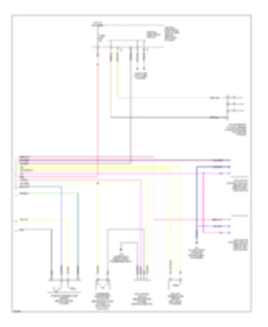
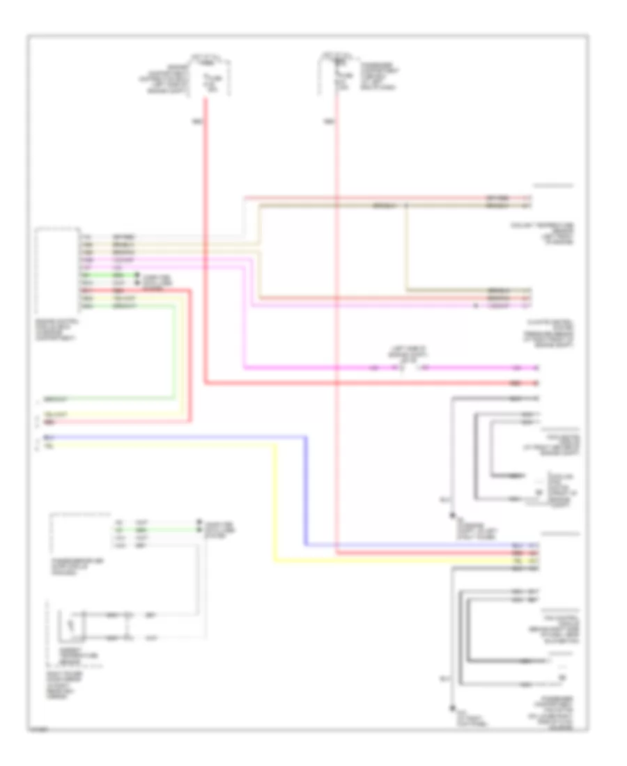
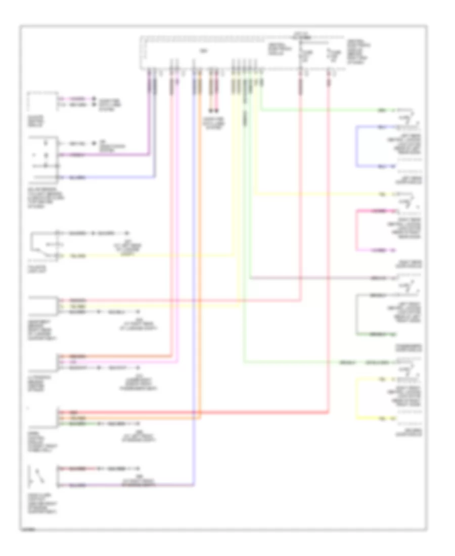
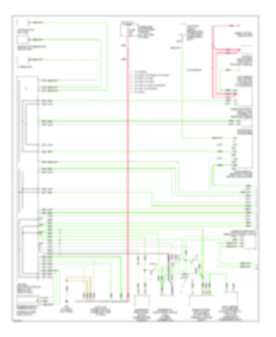
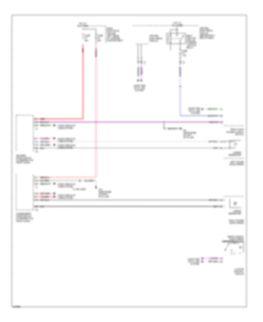
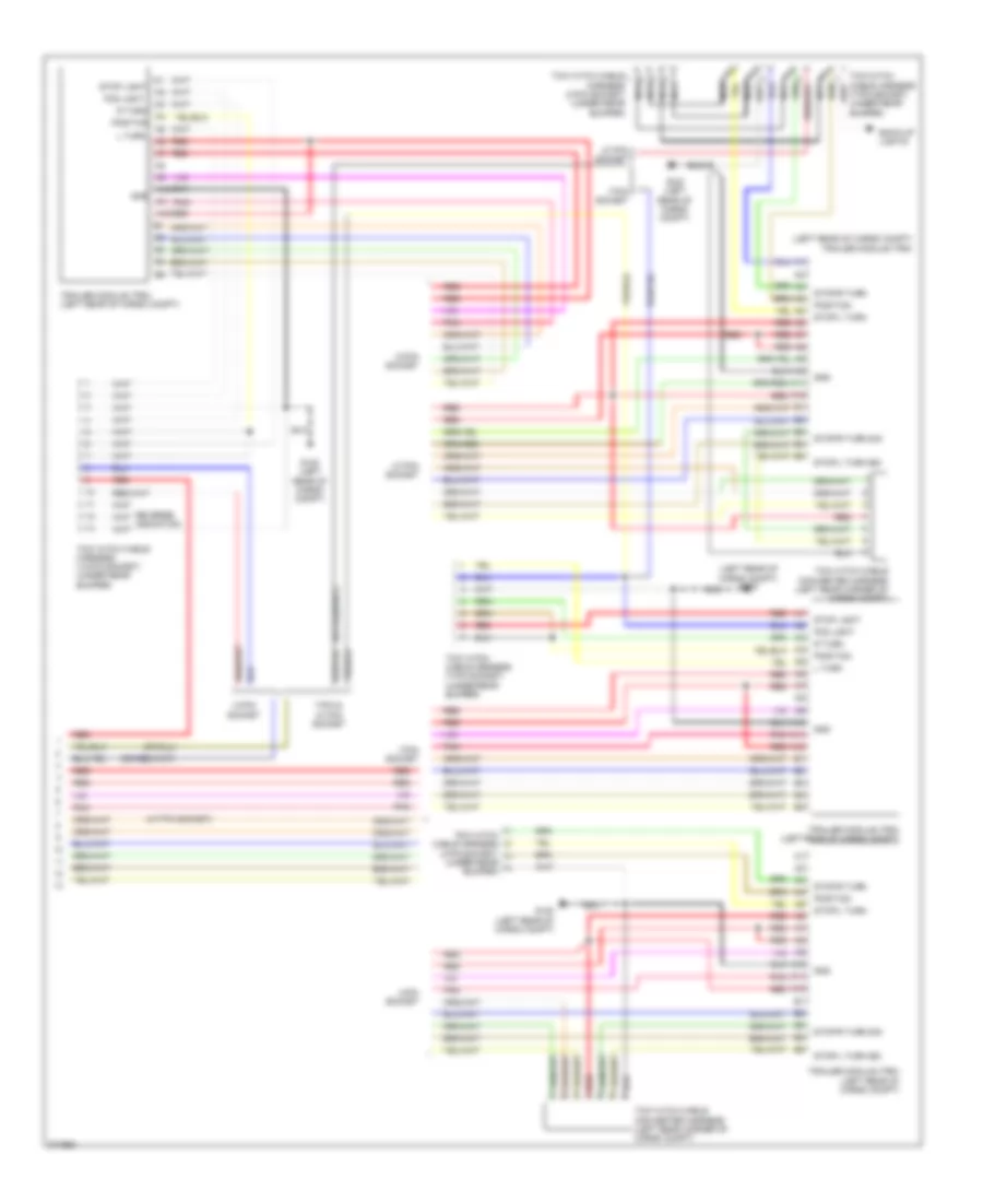
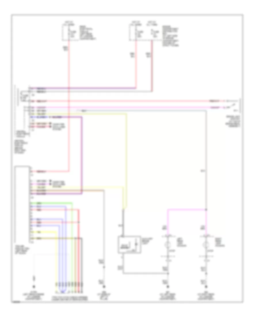
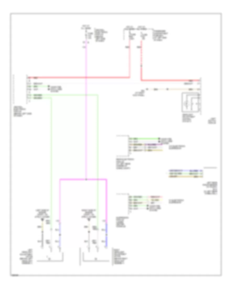
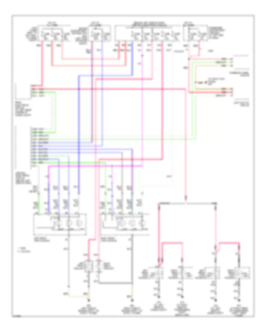
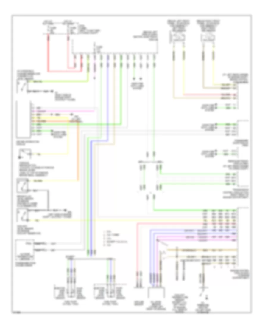
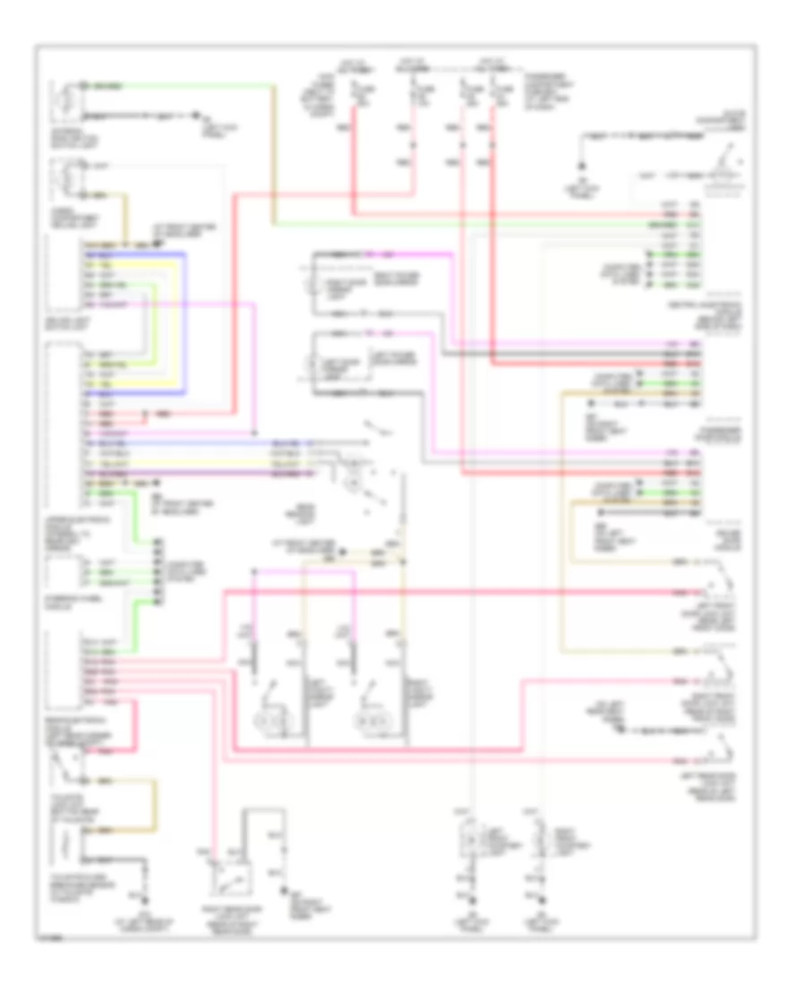
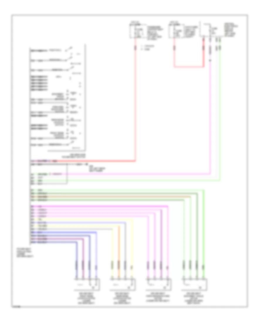
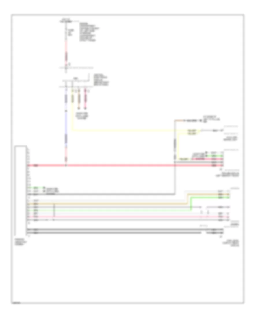
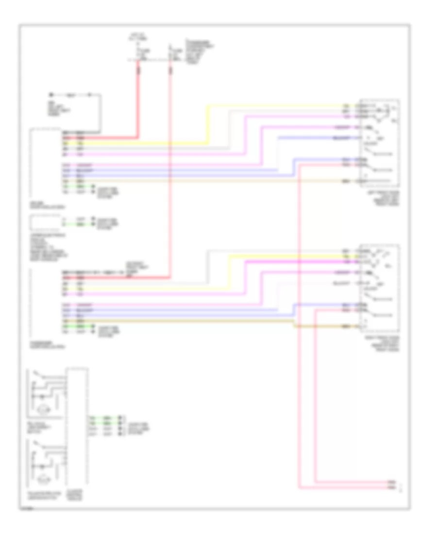
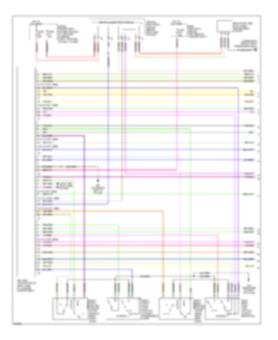
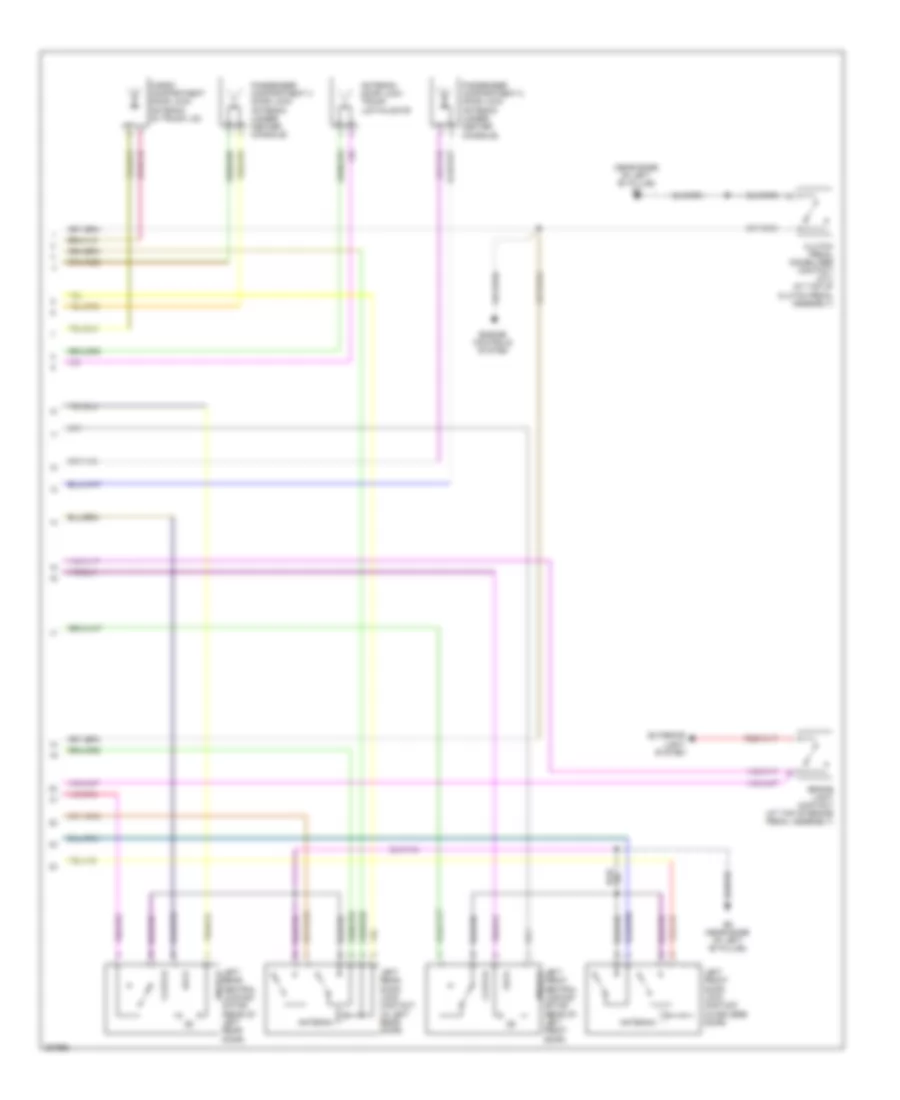
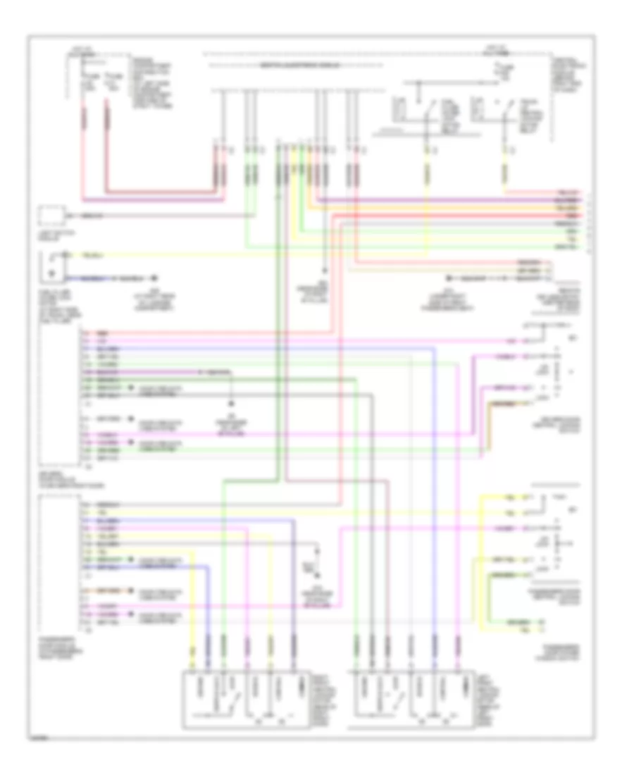
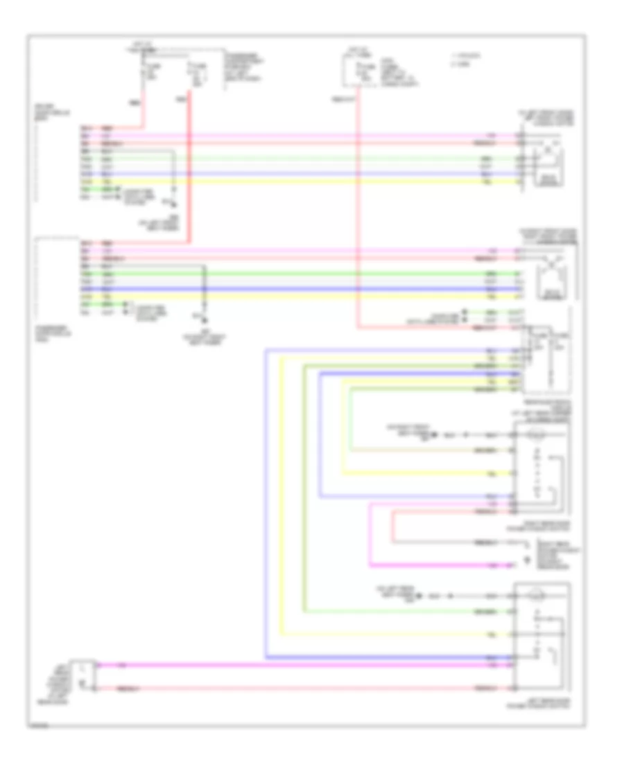
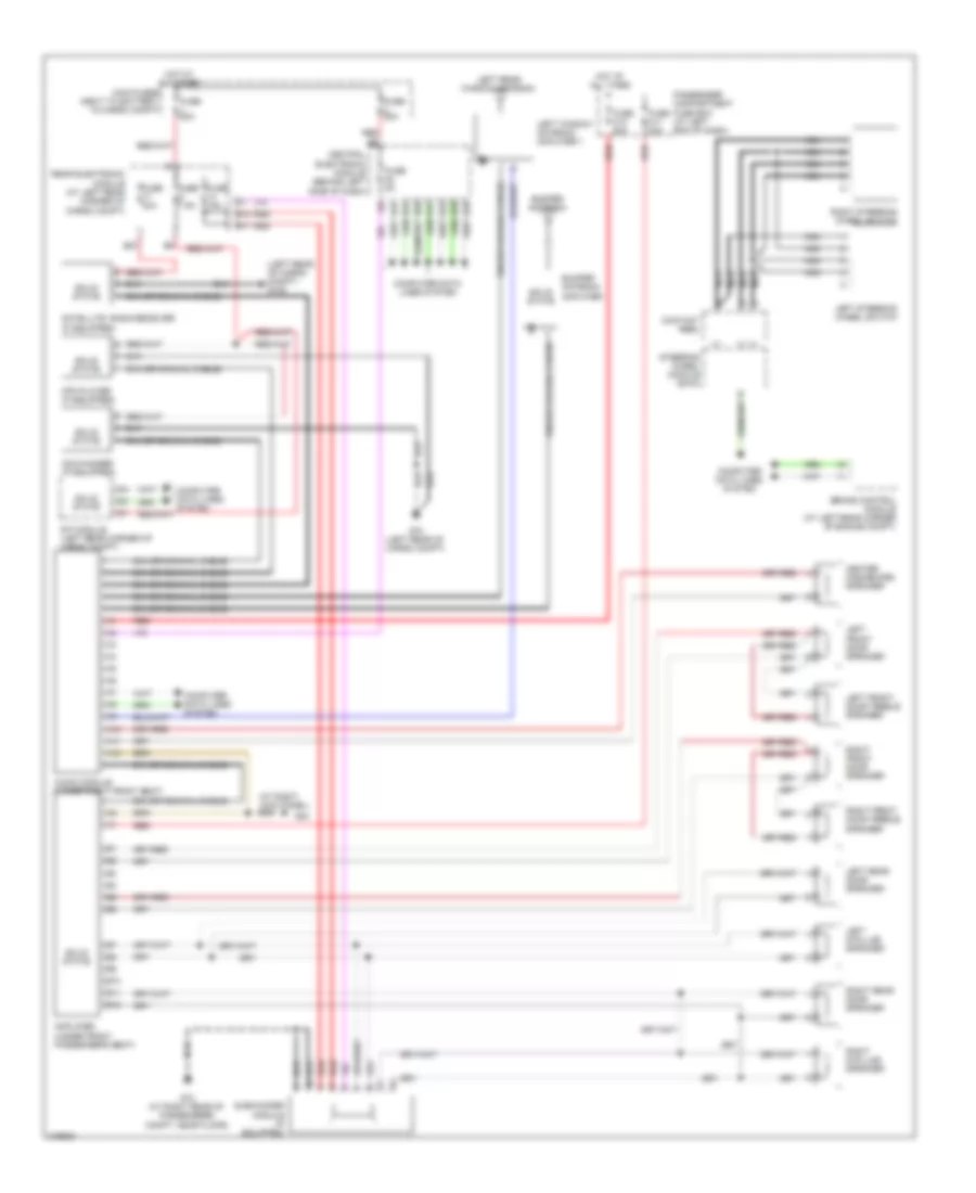
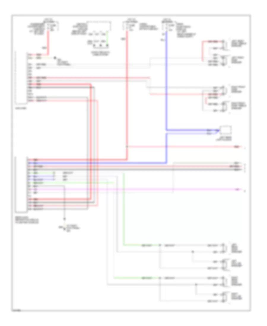
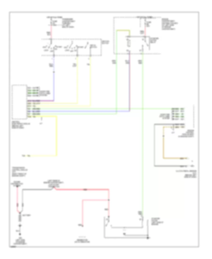
Automatic A/C Wiring Diagram, Late Production (1 of 2) for Volvo V70 2008
 https://portal-diagnostov.com/license.html
Automotive Electricians Portal FZCO
Automotive Electricians Portal FZCO
https://portal-diagnostov.com/license.html
https://portal-diagnostov.com/license.html
Automotive Electricians Portal FZCO
Automotive Electricians Portal FZCO
List of elements for Automatic A/C Wiring Diagram, Late Production (1 of 2) for Volvo V70 2008:
- 3.2l
- 4.4l
- A12
- A13
- A49
- A68
- A85
- Air quality sensor (aqs) (on hvac assembly)
- B10
- B12
- B16
- B19
- B27
- B29
- B31
- B34
- B35
- B49
- B51
- B53
- Climate control module
- Climate control system
- Climate control system electromagnetic clutch (left front of engine)
- Climate control system pressure sensor (on hvac assembly)
- Climate control system relay
- Comfort functions relay
- Computer data lines system
- Defroster damper motor module (dmm) (on hvac assembly)
- Engine compartment distribution box (at left side of engine compartment, forward of strut tower)
- Engine control module (ecm) (left rear of engine compt)
- Engine management system main relay
- Evaporator temperature sensor (behind center of dash, on evaporator assembly)
- Floor/ventilation damper motor module (dmm) (behind center of dash, on right side of hvac unit)
- Fuse a43 50a
- Fuse a44 60a
- Fuse b11 40a
- Fuse b26 10a
- Fuse b30 10a
- Fuse b32 15a
- Fuse b33 5a
- Fuse b38 10a
- G10 (under right side of front passenger's seat)
- G83 (under driver's door sill)
- Hot at all times
- Left power door mirror
- Left temperature damper motor module (dmm) (on hvac assembly)
- Outside temperature sensor
- Pnk
- Recirculation damper motor module (dmm) (bottom of damper motor, under right side of dash)
- Red
- Right temperature damper motor module (dmm) (on hvac assembly)
- Solid state
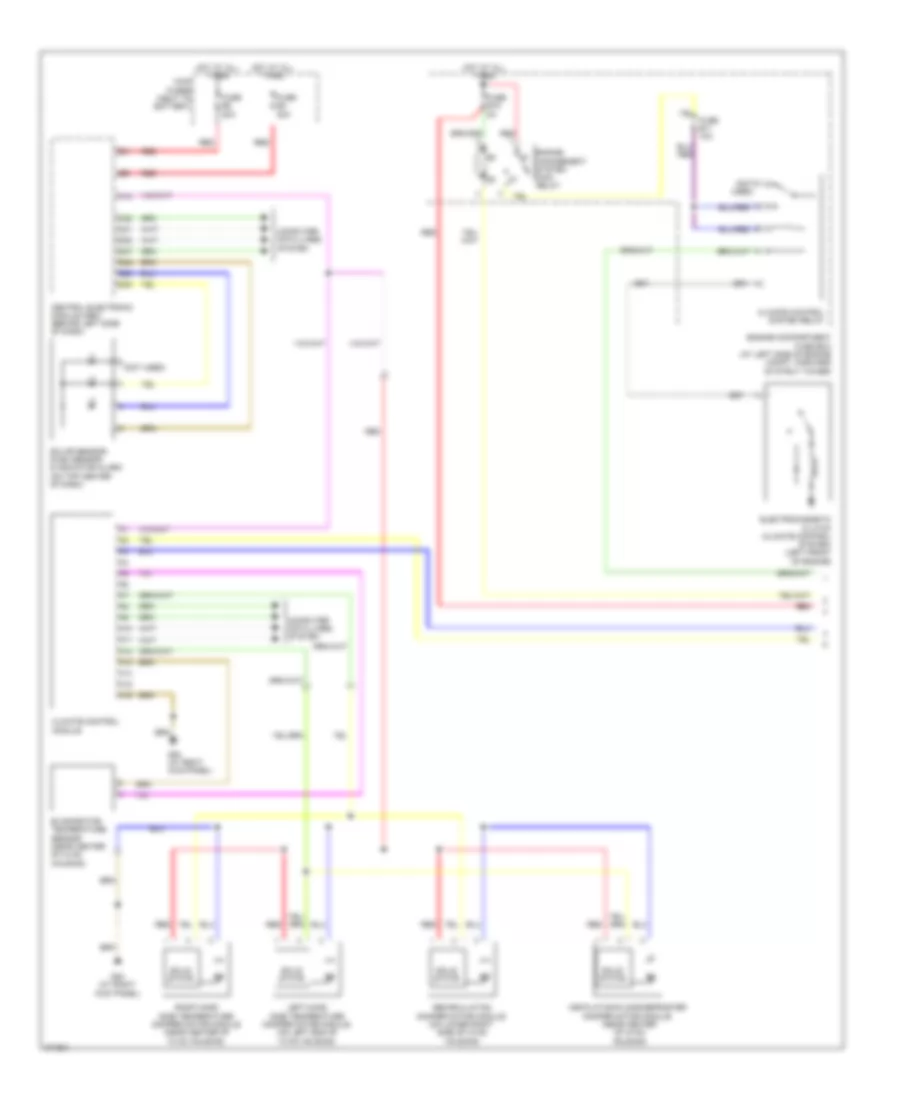
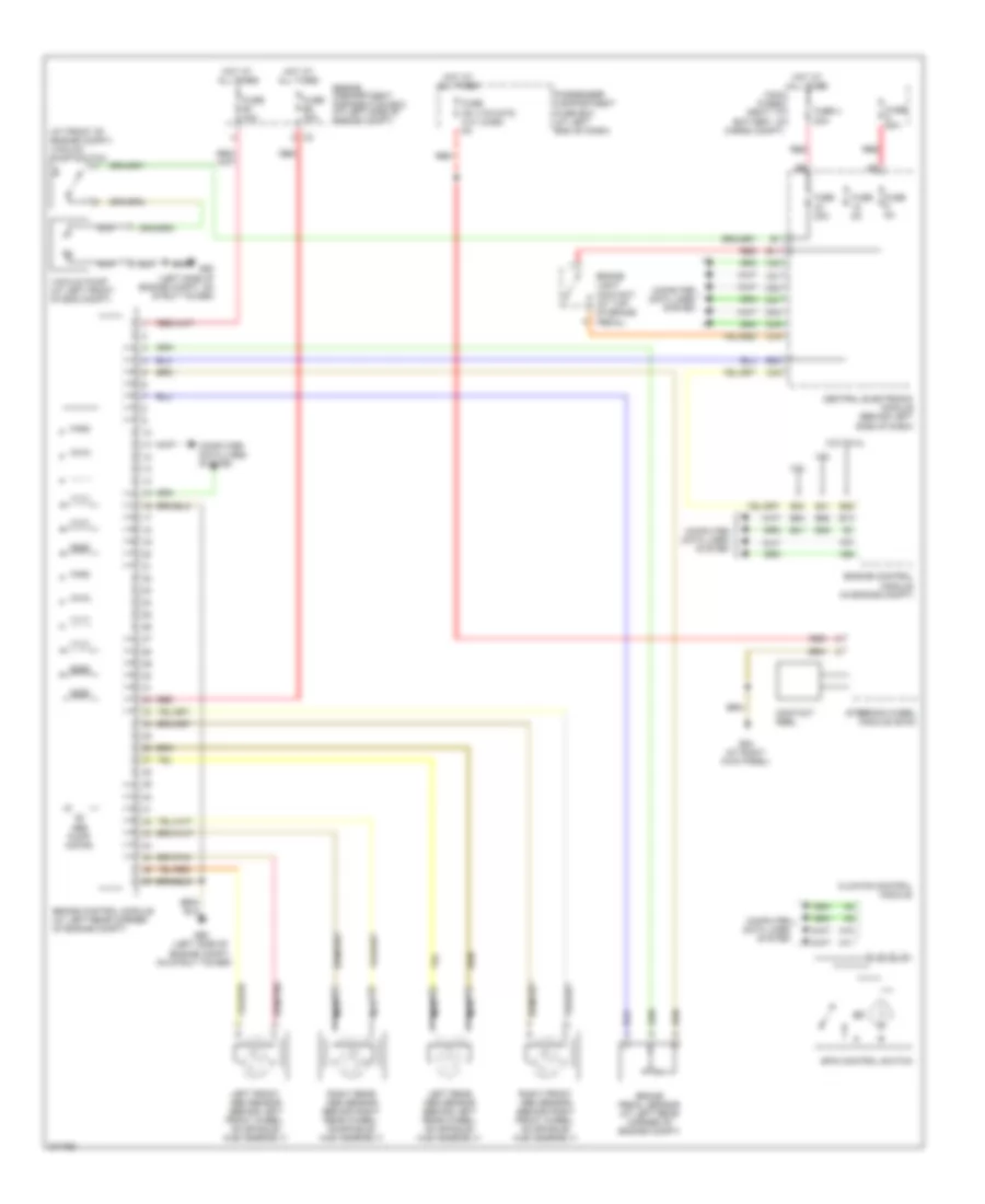
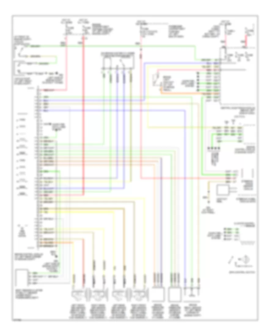
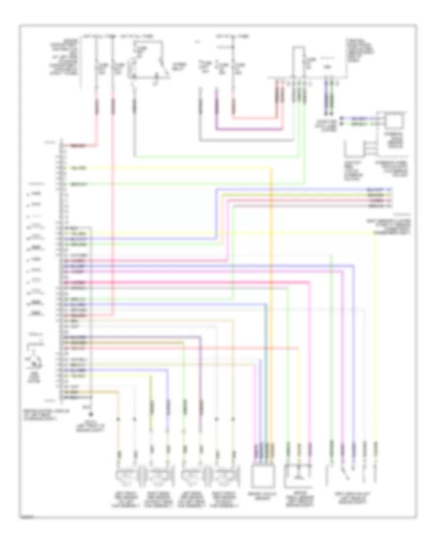
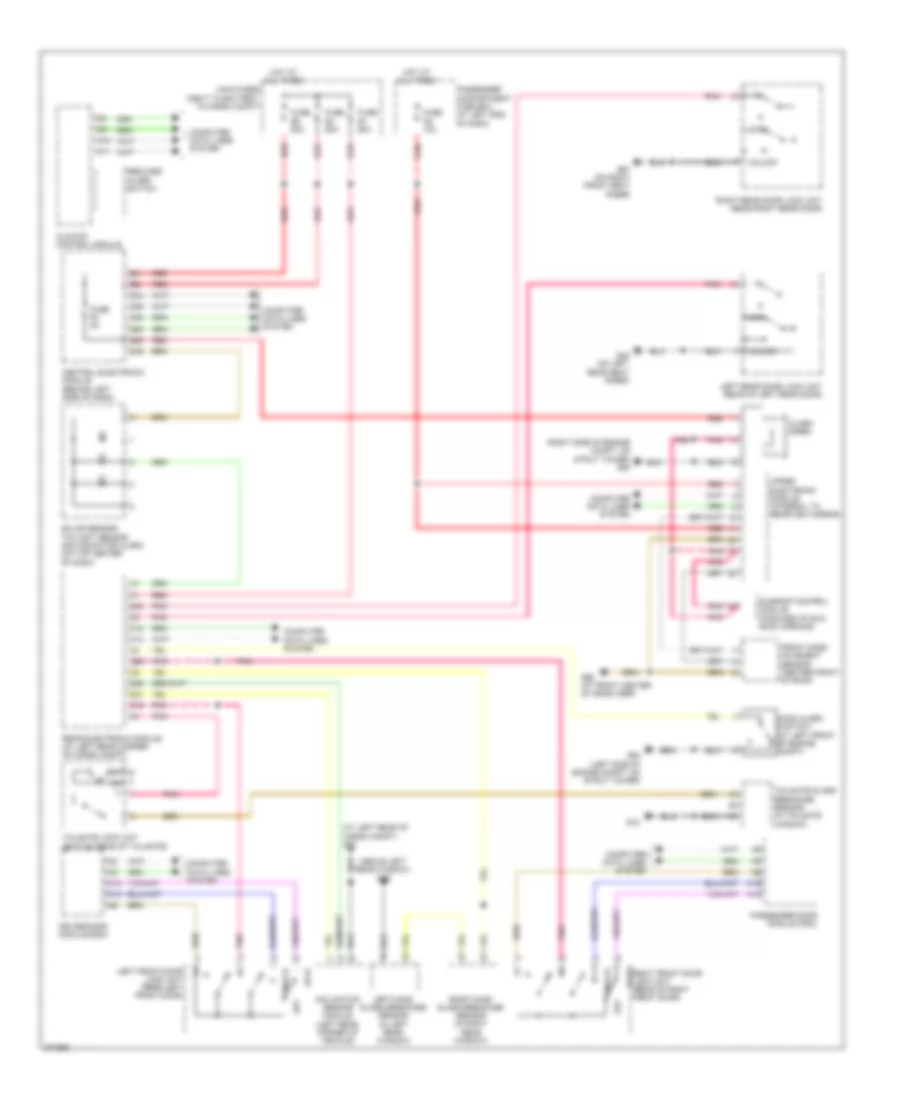
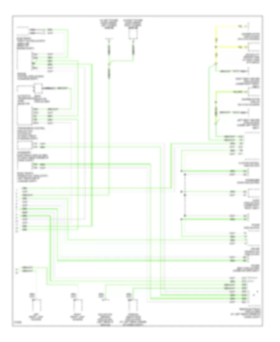
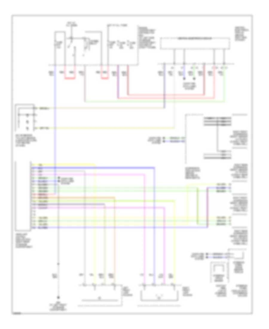
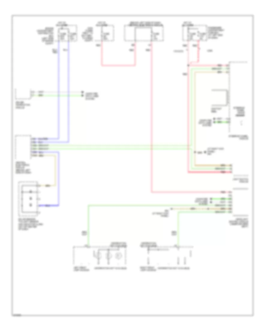
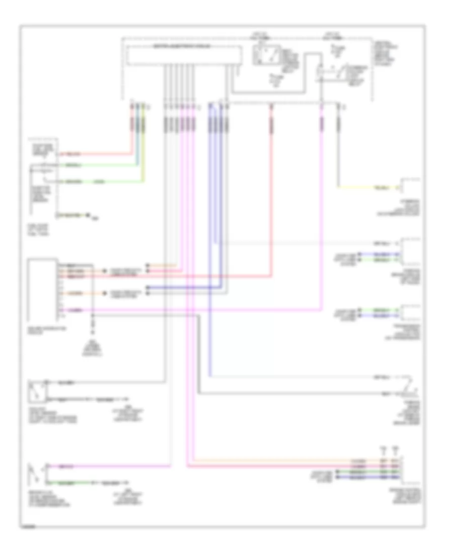
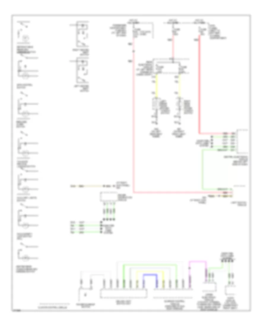
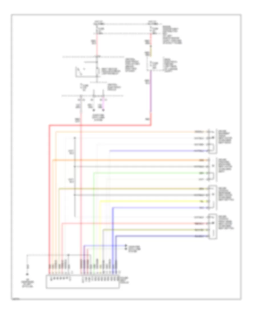
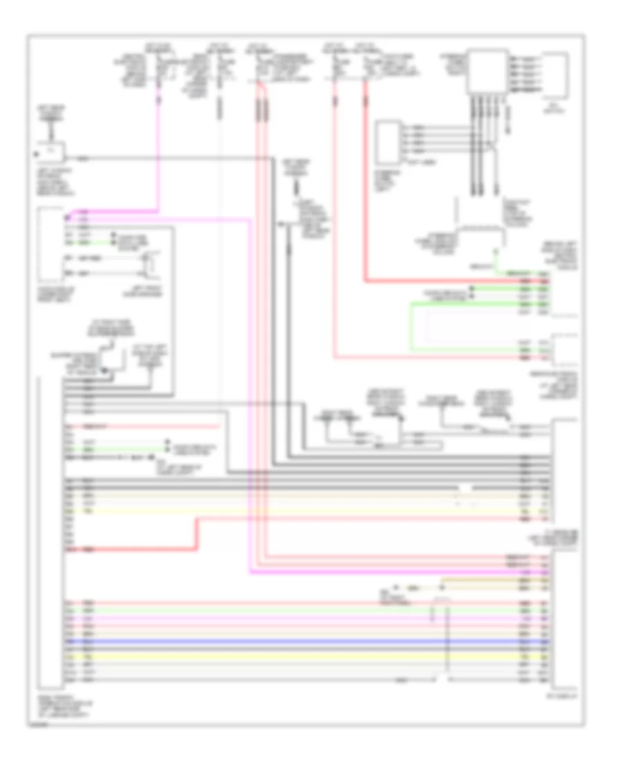
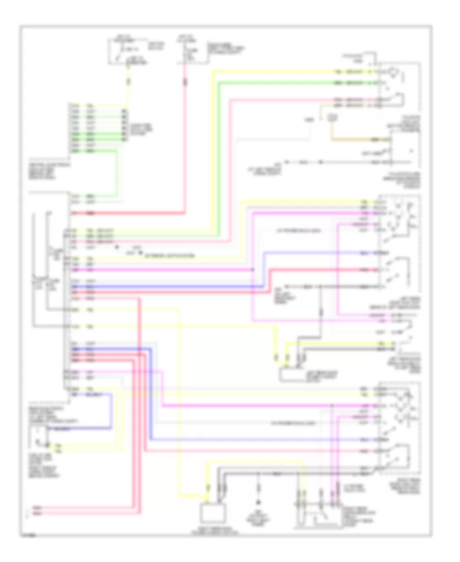
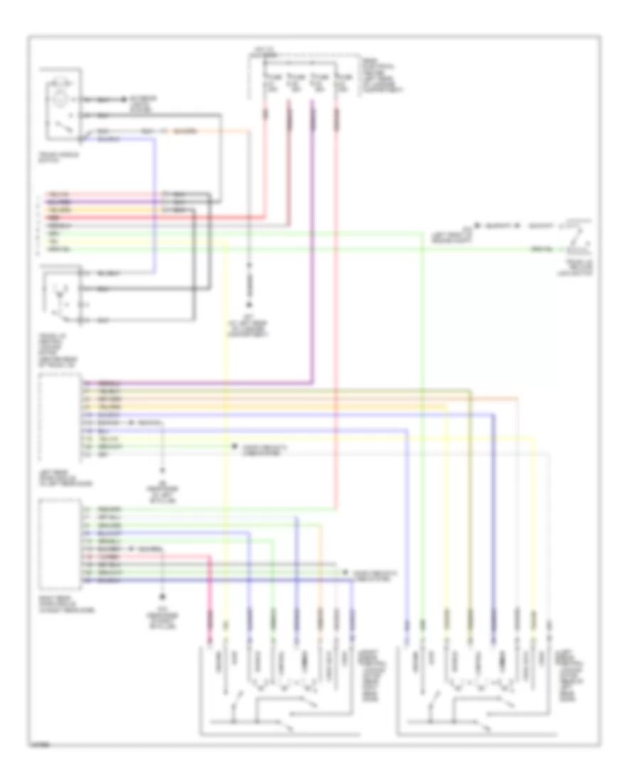
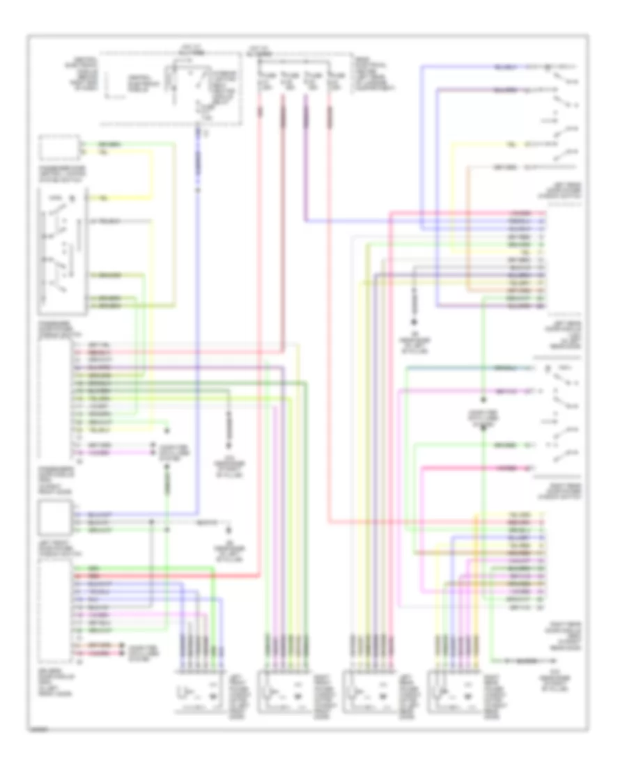
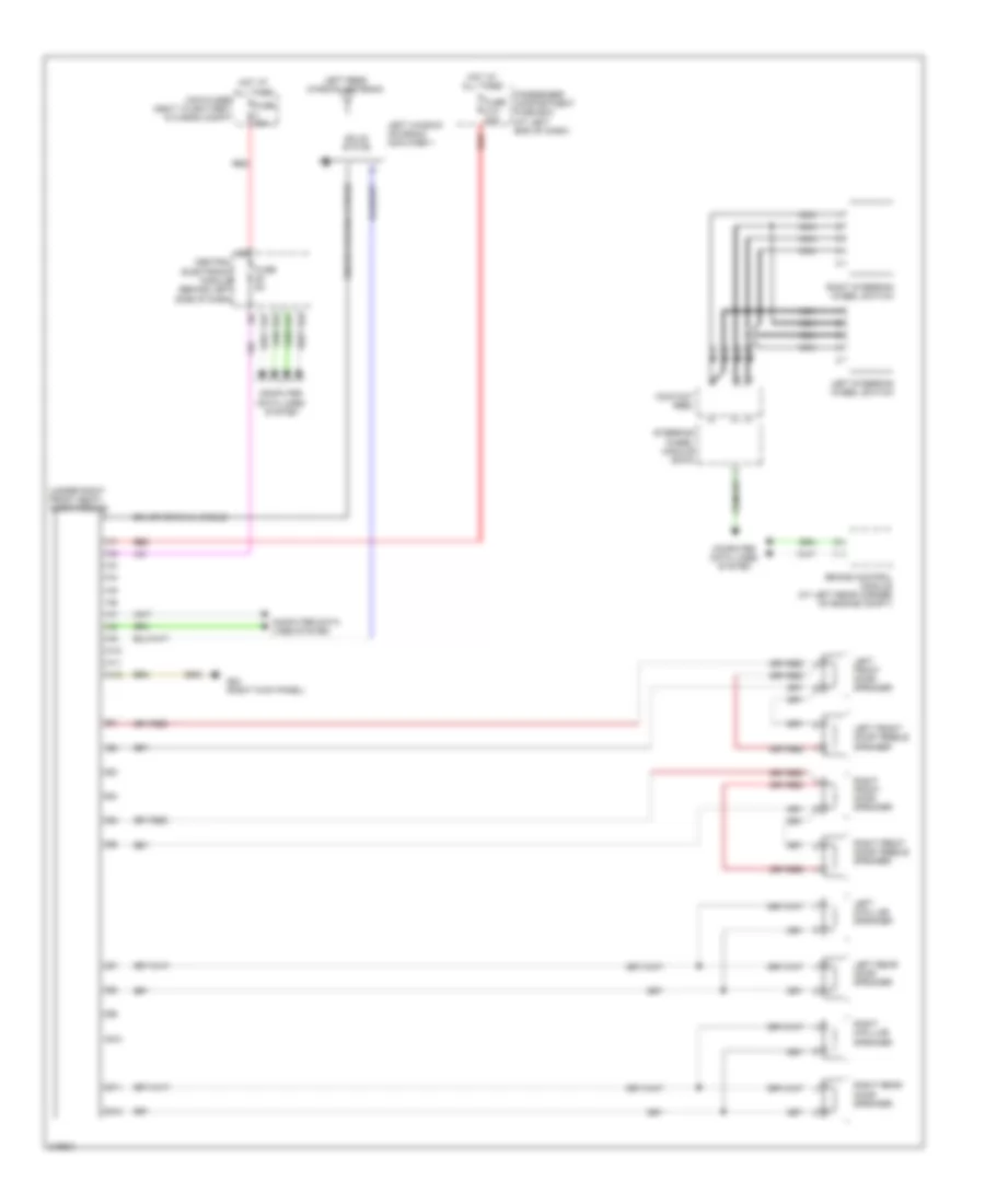
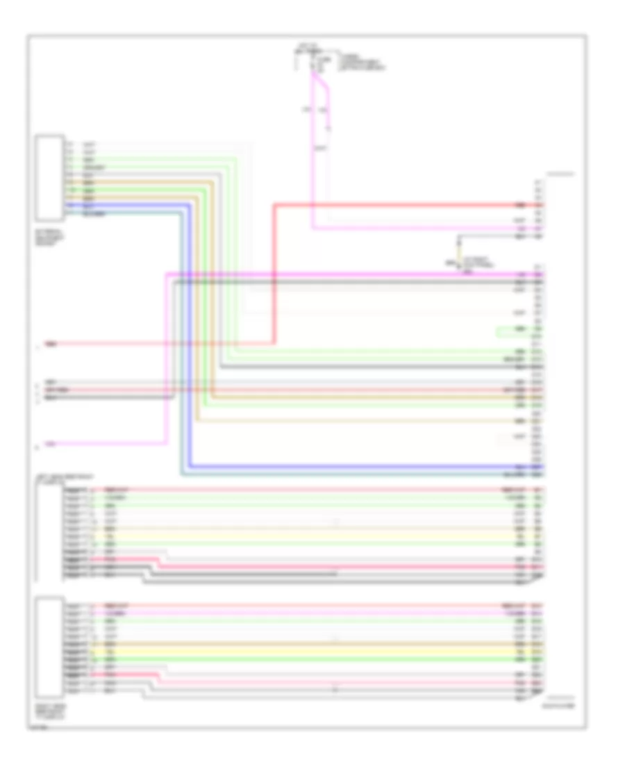
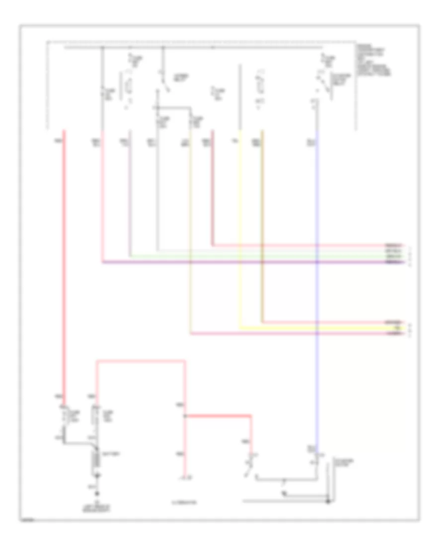
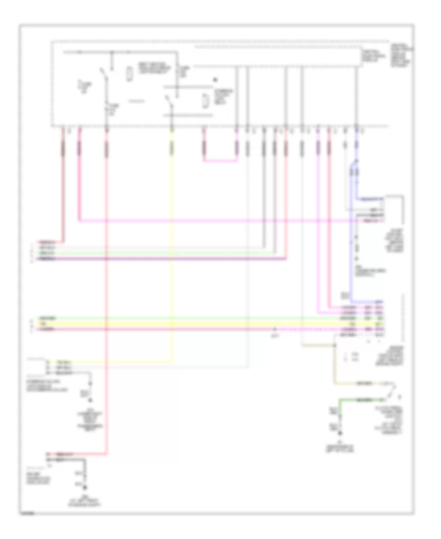
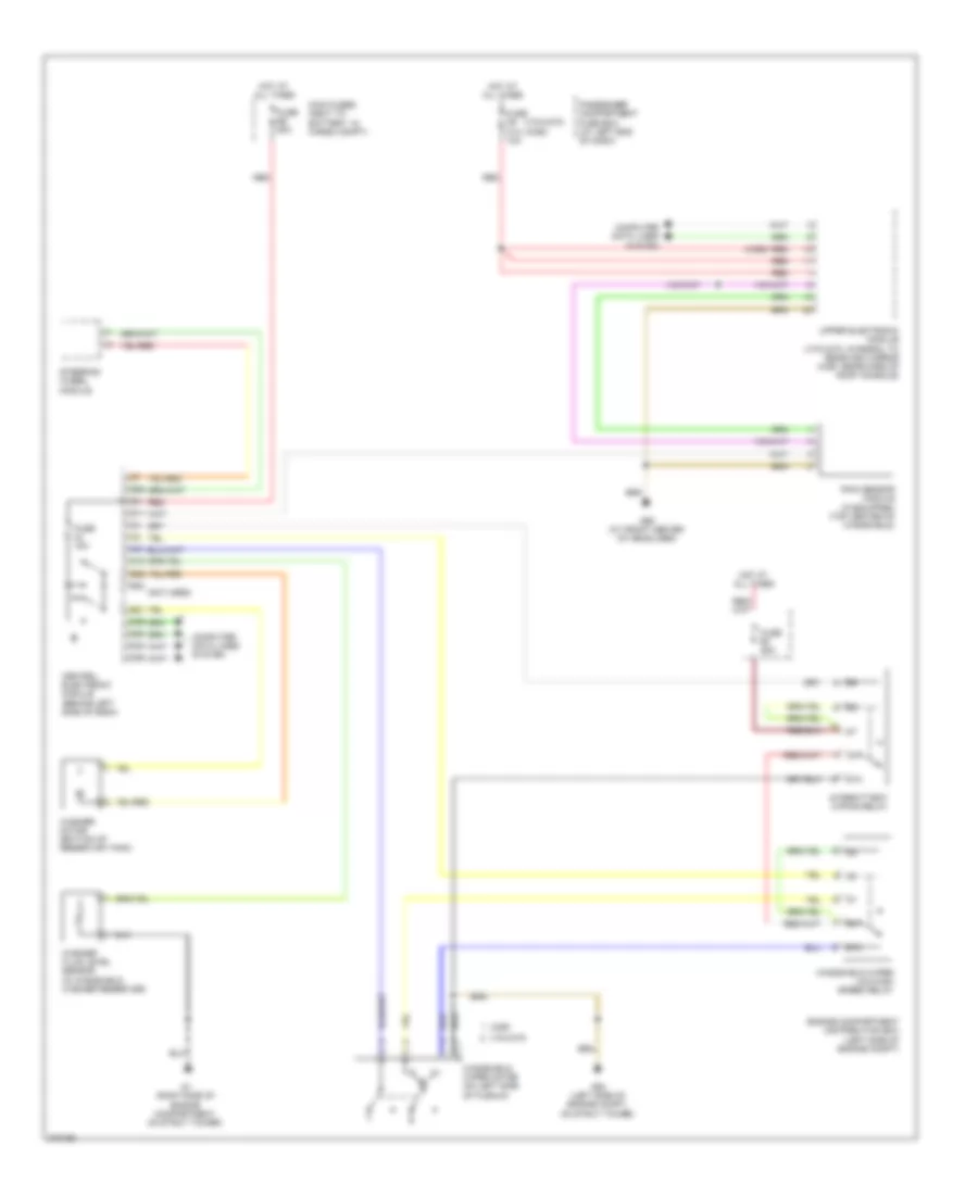
Automatic A/C Wiring Diagram, Late Production (2 of 2) for Volvo V70 2008
List of elements for Automatic A/C Wiring Diagram, Late Production (2 of 2) for Volvo V70 2008:
- Central electronic module
- Central electronic module (cem) (behind right end of dash)
- Computer data lines system
- Coolant temperature sensor (left front of engine)
- Cooling fan control module (behind left side of left cooling fan)
- Cooling fan control module 2 (behind left side of right cooling fan)
- Fan control module (behind center of dash, near blower fan)
- Fuse f26 5a
- G10 (under right side of front passenger's seat)
- G2 (at left front of engine compartment, on fender)
- Hot at all times
- Interior temperature sensor (behind center of dash)
- Passenger compartment fan motor (behind right side of dash, in right end of hvac unit)
- Red
- Solar sensor, twilight sensor & indicator alarm (top center of dash)
2.4L
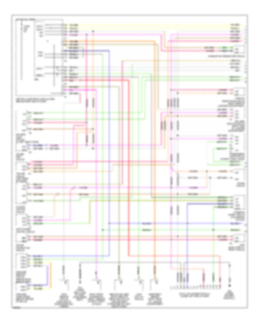
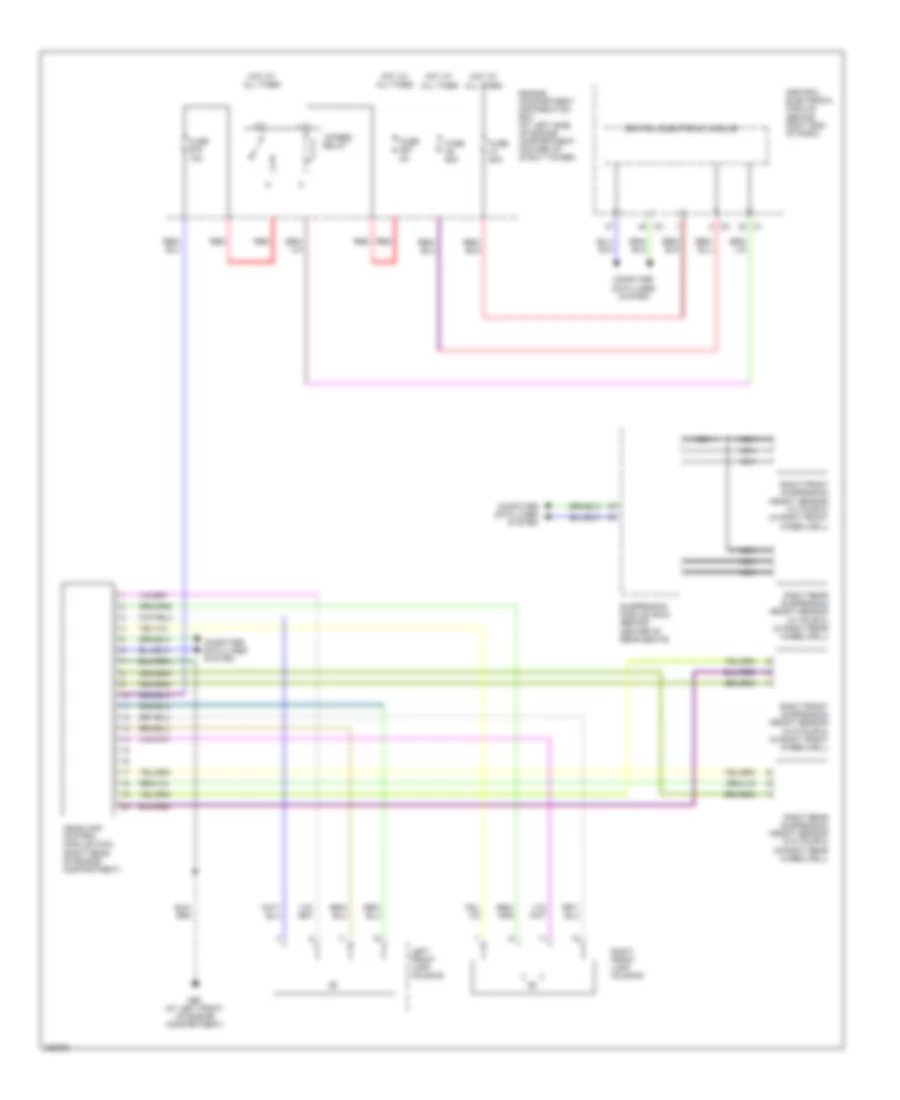
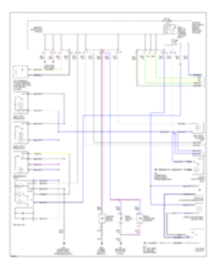
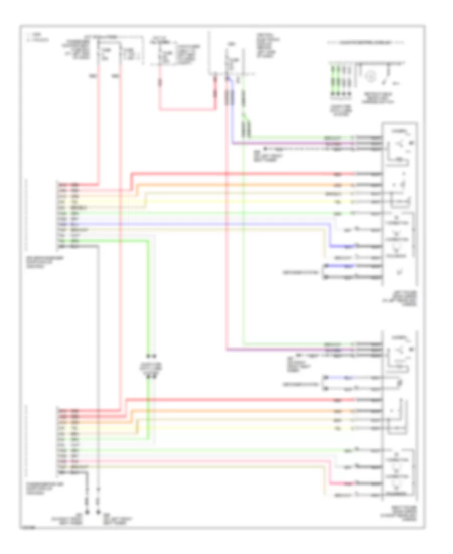
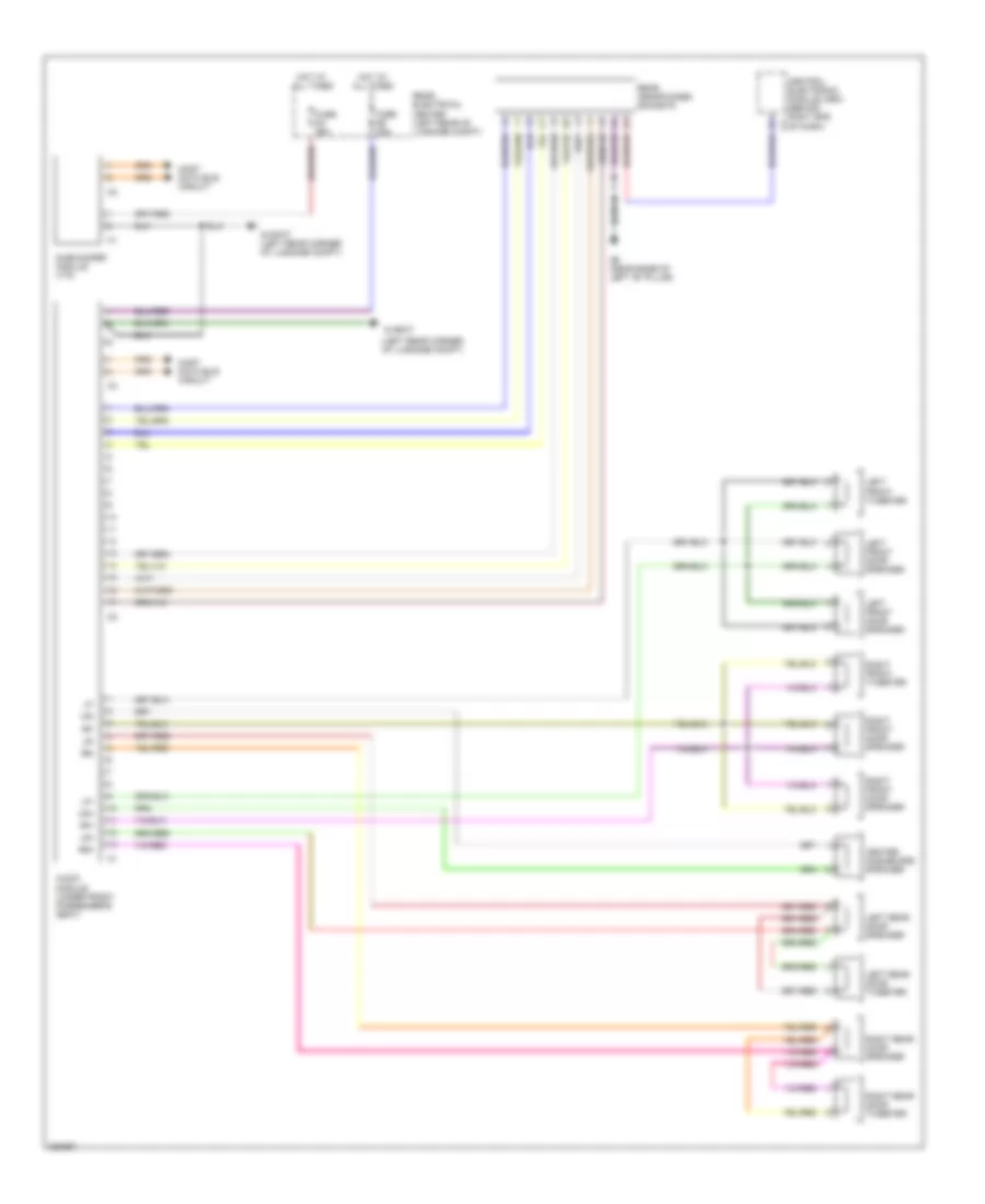
2.4L, Manual A/C Wiring Diagram, Early Production (1 of 2) for Volvo V70 2008
List of elements for 2.4L, Manual A/C Wiring Diagram, Early Production (1 of 2) for Volvo V70 2008:
- (not used)
- A10
- A11
- A12
- A13
- A14
- A15
- A16
- C21
- C22
- Central electronic module (cem) (behind left side of dash)
- Climate control module
- Climate control system relay
- Computer data lines system
- D29
- D30
- D32
- D42
- D47
- Electromagnetic clutch (climate control system) (left front of engine)
- Engine compartment fuse box (at left side of engine compt, forward of strut tower)
- Engine management system main relay
- Evaporator temperature sensor (near center of hvac housing)
- Fuse b11 10a
- Fuse b19 5a
- Fuse e4 50a
- Fuse e5 50a
- G84 (at right kick panel)
- Hot at all times
- Left-hand side temperature damper motor module (on left end of hvac housing)
- Main fuses (next to battery)
- Recirculation damper motor module (on lower right side of hvac housing)
- Red
- Right-hand side temperature damper motor module (near center of hvac housing)
- Solar sensor, dusk sensor & indicator alarm (on top center of dash)
- Solid state
- Ventilation/floor/defroster damper motor module (near center of hvac housing)
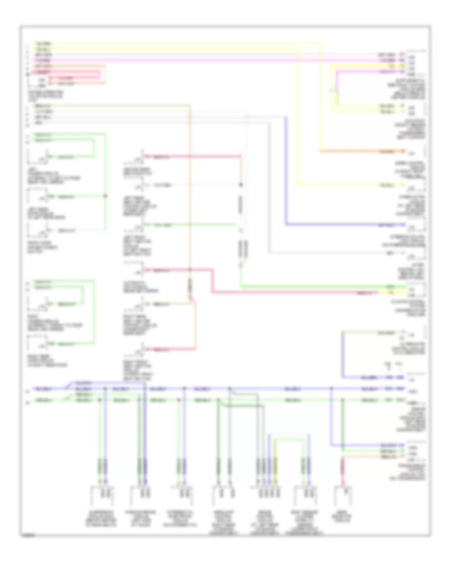
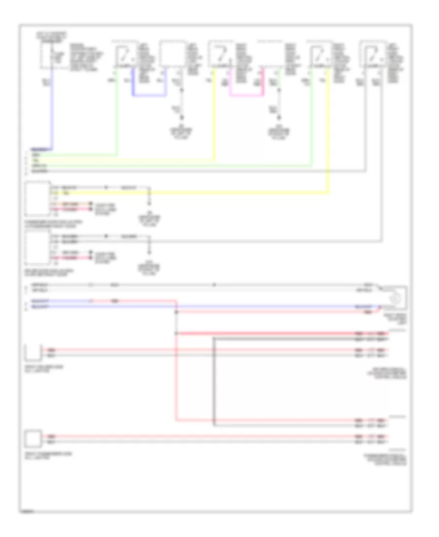
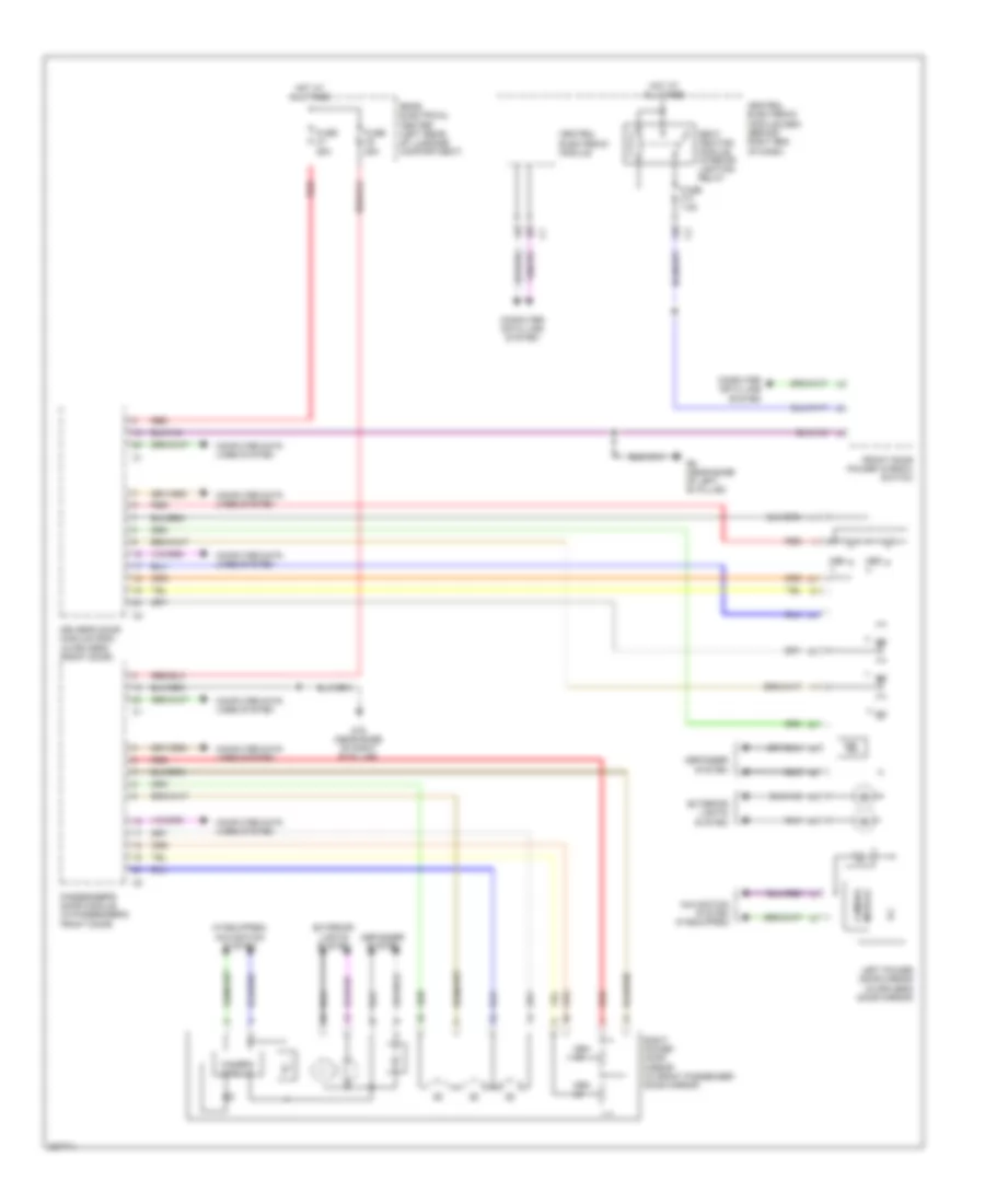
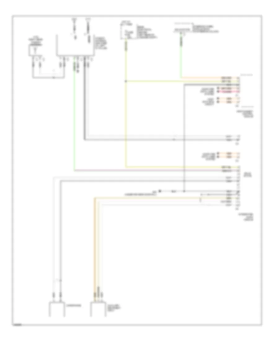
2.4L, Manual A/C Wiring Diagram, Early Production (2 of 2) for Volvo V70 2008
List of elements for 2.4L, Manual A/C Wiring Diagram, Early Production (2 of 2) for Volvo V70 2008:
- (left side of engine compt) 54/1b
- A14
- A18
- A21
- A37
- A40
- A55
- A58
- A61
- Ambient temperature sensor
- B11
- B13
- B38
- B44
- Climate control system pressure sensor (at right front of engine compt)
- Computer data lines system
- Coolant temperature sensor (left front of engine)
- Cooling fan module (at front center of engine compt)
- Cooling fan motor (front of engine compt)
- Engine compartment distribution box (left side of engine compt)
- Engine control module (ecm) (in engine compartment)
- Fan control module (behind right side of dash, near blower fan)
- Fuse a2 60a
- Fuse c3 30a
- G10 (at right kick panel)
- G2 (in engine compt, on left strut tower)
- Hot at all times
- Nca
- Passenger compartment fan motor (on lower right side of hvac housing)
- Passenger compartment fuse box (left end of dash)
- Passenger/driver door module (pdm/ddm)
- Red
- Right power door mirror (in right rearview mirror)
- Solid state
2.5L TURBO
2.5L Turbo, Automatic A/C Wiring Diagram, Early Production (1 of 2) for Volvo V70 2008
List of elements for 2.5L Turbo, Automatic A/C Wiring Diagram, Early Production (1 of 2) for Volvo V70 2008:
- (not used)
- A10
- A11
- A12
- A13
- A14
- A15
- A16
- Air quality sensor (at right side of plenum)
- C21
- C22
- Central electronic module (cem) (behind left side of dash)
- Climate control module
- Climate control system relay
- Computer data lines system
- D29
- D30
- D32
- D42
- D47
- Defroster damper motor module (near center of hvac housing)
- Electromagnetic clutch (climate control system) (left front of engine)
- Engine compartment fuse box (at left side of engine compt, forward of strut tower)
- Engine management system main relay
- Evaporator temperature sensor (near center of hvac housing)
- Floor/ventilation damper motor module (near center of hvac housing)
- Fuse b11 10a
- Fuse b19 5a
- Fuse e4 50a
- Fuse e5 50a
- G84 (at right kick panel)
- Hot at all times
- Left-hand side temperature damper motor module (on left end of hvac housing)
- Main fuses (next to battery)
- Recirculation damper motor module (on lower right side of hvac housing)
- Red
- Right-hand side temperature damper motor module (near center of hvac housing)
- Solar sensor, dusk sensor & indicator alarm (on top center of dash)
- Solid state
2.5L Turbo, Automatic A/C Wiring Diagram, Early Production (2 of 2) for Volvo V70 2008
List of elements for 2.5L Turbo, Automatic A/C Wiring Diagram, Early Production (2 of 2) for Volvo V70 2008:
- (left side of engine compt) 54/1b
- A14
- A18
- A39
- A60
- A68
- Ambient temperature sensor
- B11
- B13
- B38
- B44
- Climate control system pressure sensor (at right front of engine compt)
- Computer data lines system
- Coolant temperature sensor (left front of engine)
- Cooling fan module (at front center of engine compt)
- Cooling fan motor (front of engine compt)
- Engine compartment distribution box (left side of engine compt)
- Engine control module (ecm) (in engine compartment)
- Fan control module (behind right side of dash, near blower fan)
- Fuse a2 60a
- Fuse c3 30a
- G10 (at right kick panel)
- G2 (in engine compt, on left strut tower)
- Hot at all times
- Nca
- Passenger compartment fan motor (on lower right side of hvac housing)
- Passenger compartment fuse box (at left end of dash)
- Passenger/driver door module (pdm/ddm)
- Red
- Right power door mirror (in right rearview mirror)
ANTI-LOCK BRAKES
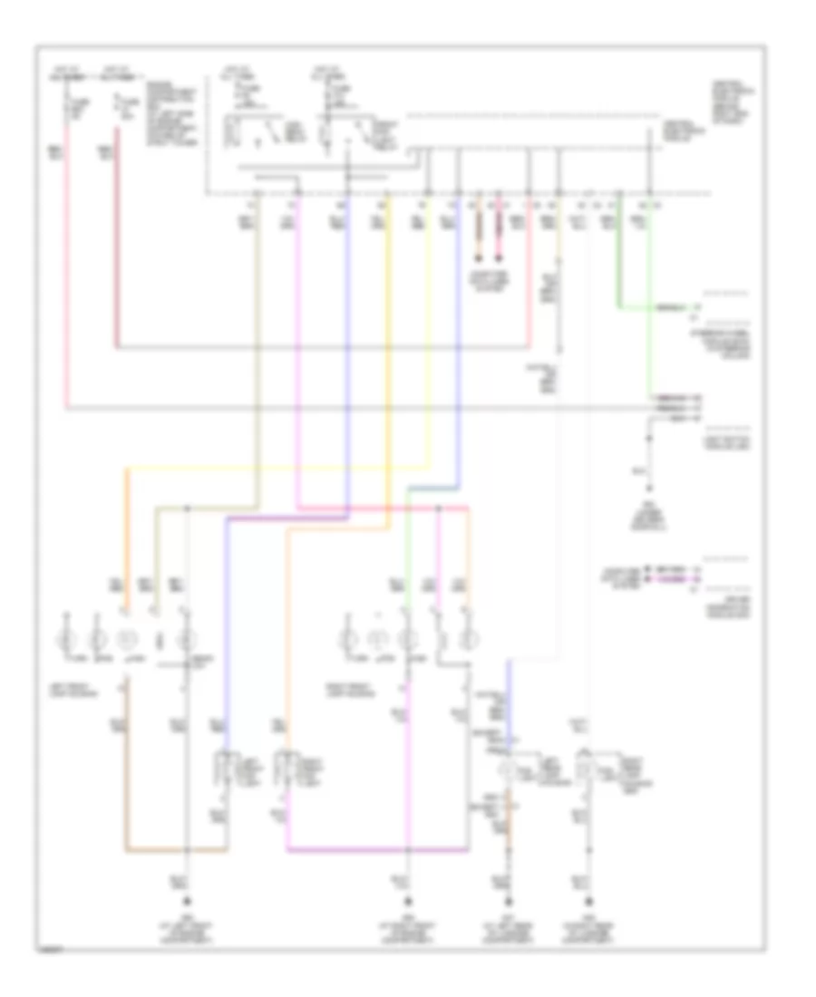
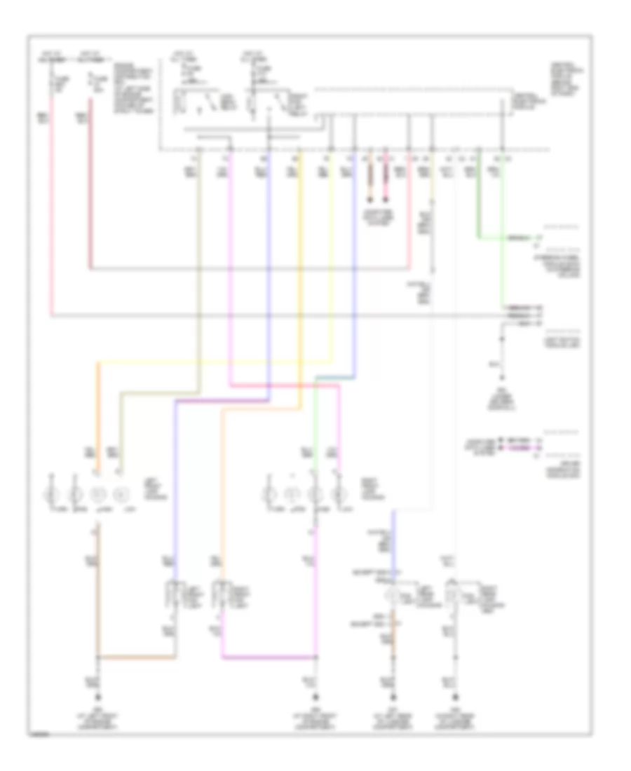
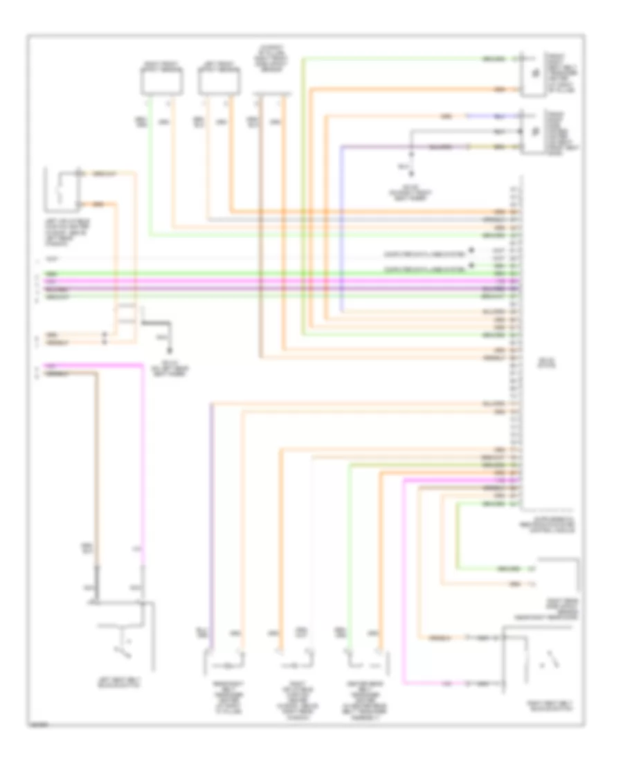
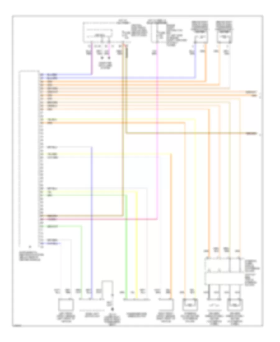
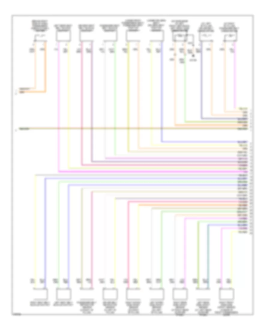
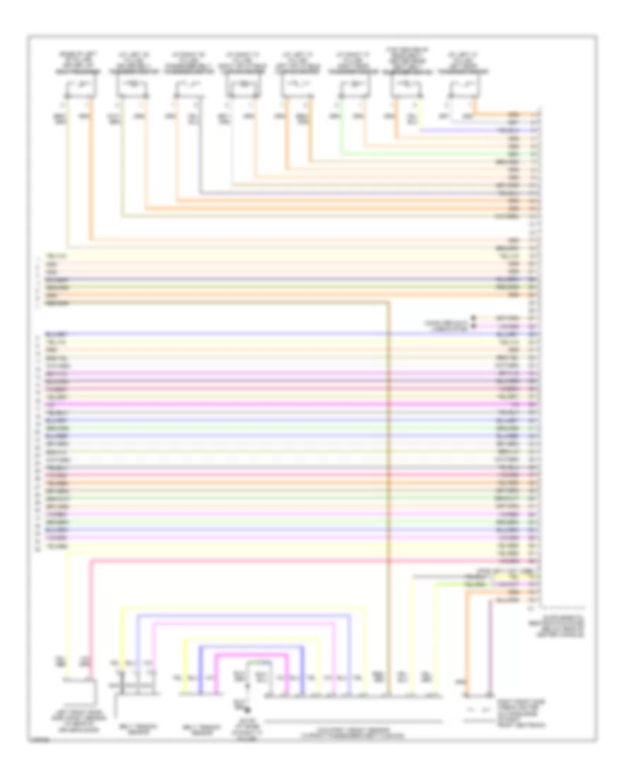
Anti-lock Brakes Wiring Diagram, Early Production with Dynamic Stability Control for Volvo V70 2008
List of elements for Anti-lock Brakes Wiring Diagram, Early Production with Dynamic Stability Control for Volvo V70 2008:
- (at front of engine compt) vacuum pump switch
- (v70/xc70)
- (xc90)
- 2.5lt/2.4l
- 3.2l
- 4.4l
- A10
- A11
- A37
- A55
- Abs pump motor
- B11
- B13
- B22
- B26
- B30
- B41
- B45
- B54
- B58
- Brake control module (at left rear corner of engine compt)
- Brake light contact (at top of brake pedal)
- Brake pedal sensor (at left rear corner of engine compt)
- C21
- C22
- C34
- C35
- Central electronic module (behind left side of dash)
- Climate control module
- Computer data lines system
- Contact reel
- D32
- D34
- D47
- D49
- Engine compartment distribution box (at left side of engine compt)
- Engine control module (in engine compt)
- Fuse 20a
- Fuse 4 50a
- Fuse 50a
- Fuse 5a
- Fuse b1 30a
- Fuse b2 30a
- Fuse c9 c10 5a
- G84 (at right kick panel)
- G93 (left side of engine compt, on strut tower)
- G95 (left side of engine compt,
- Hot at all times
- Left front abs sensor (behind left front wheel, on spindle/ hub assembly)
- Left rear abs sensor (behind left rear wheel, on spindle/ hub assembly)
- Main fuses (next to battery, in cargo compt)
- Nca
- On strut tower)
- Passenger compartment fuse box (at left end of dash)
- Red
- Right front abs sensor (behind right front wheel, on spindle/ hub assembly)
- Right rear abs sensor (behind right rear wheel, on spindle/ hub assembly)
- Spin control switch
- Steering wheel module (swm)
- Vacuum pump (at left front of eng compt)
Anti-lock Brakes Wiring Diagram, Early Production without Dynamic Stability Control for Volvo V70 2008
List of elements for Anti-lock Brakes Wiring Diagram, Early Production without Dynamic Stability Control for Volvo V70 2008:
- (at front of engine compt) vacuum pump switch
- (left side of engine compt,
- (on brake master cylinder) dstc activation unit
- (v70/xc70)
- (xc90)
- 2.5lt/2.4l
- 3.2l
- 4.4l
- A10
- A11
- A37
- A55
- Abs pump motor
- B11
- B13
- B22
- B26
- B30
- B41
- B45
- B54
- B58
- Body sensor cluster stability sensor (under front passenger's seat)
- Brake control module (at left rear corner of engine compt)
- Brake light contact (at top of brake pedal)
- Brake pedal sensor (at left rear corner of engine compt)
- Brake pressure sensor 1 (on brake master cylinder)
- Brake pressure sensor 2 (on brake master cylinder)
- C21
- C22
- C34
- C35
- Central electronic module (behind left side of dash)
- Climate control module
- Computer
- Computer data lines system
- Contact reel
- D31
- D32
- D34
- D46
- D47
- D49
- Data lines system
- Engine compartment distribution box (at left side of engine compt)
- Engine control module (in engine compt)
- Fuse 20a
- Fuse 4 50a
- Fuse 50a
- Fuse 5a
- Fuse b1 30a
- Fuse b2 30a
- Fuse c9 c10 5a
- G84 (at right kick panel)
- G93 (left side of engine compt, on strut tower)
- G95
- Hot at all times
- Left front abs sensor (behind left front wheel, on spindle/ hub assembly)
- Left rear abs sensor (behind left rear wheel, on spindle/ hub assembly)
- Main fuses (next to battery, in cargo compt)
- Nca
- On strut tower)
- Passenger compartment fuse box (at left end of dash)
- Red
- Right front abs sensor (behind right front wheel, on spindle/ hub assembly)
- Right rear abs sensor (behind right rear wheel, on spindle/ hub assembly)
- Spin control switch
- Steering angle sensor module
- Steering wheel module (swm)
- Vacuum pump (at left front of eng compt)
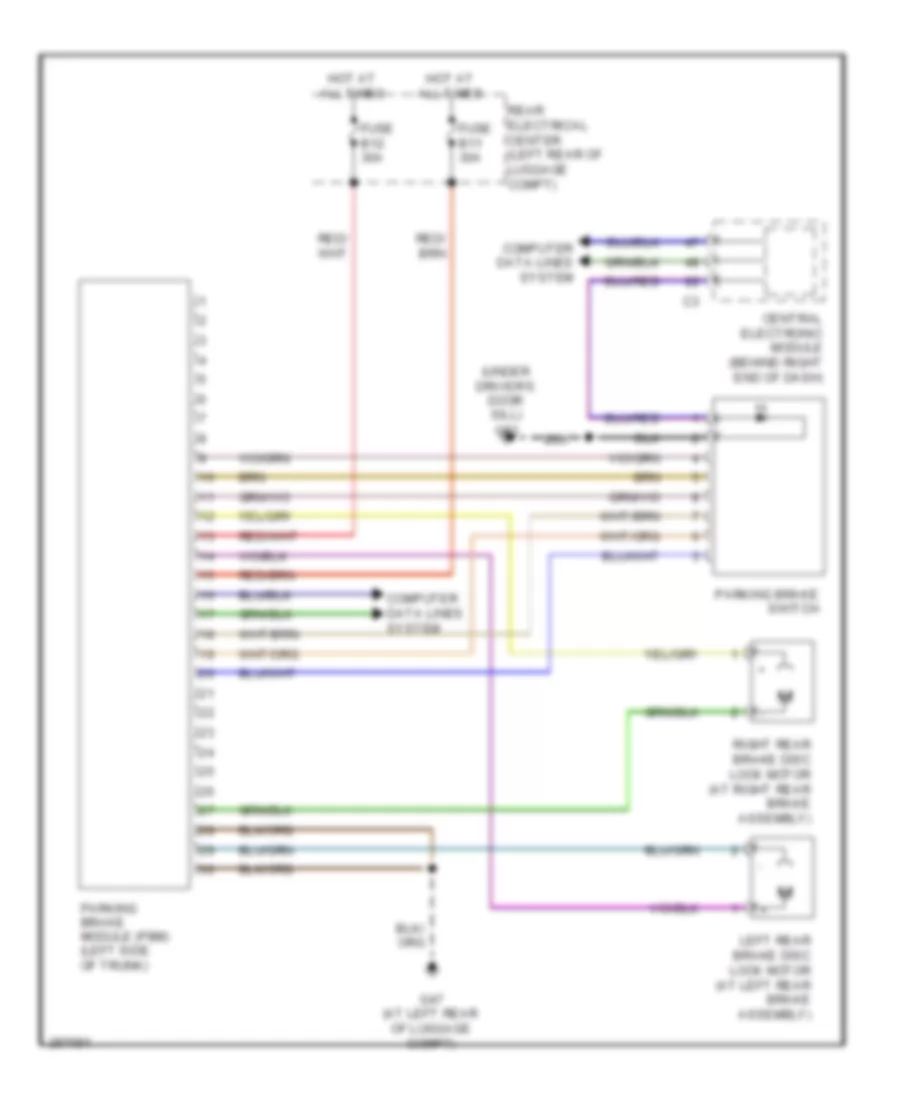
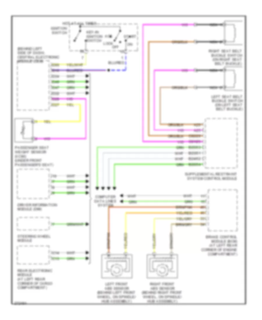
Anti-lock Brakes Wiring Diagram, Late Production for Volvo V70 2008
List of elements for Anti-lock Brakes Wiring Diagram, Late Production for Volvo V70 2008:
- (left rear of engine compt)
- 15-feed relay
- Abs pump motor
- Body sensor cluster stability sensor (under front passenger's seat)
- Brake control module (at left rear of engine compt)
- Brake pedal sensor (left rear of engine compt)
- Brake vacuum sensor
- Cem
- Central electronic module (cem) (behind right end of dash)
- Computer data lines system
- Contact reel (top of steering column)
- Dstc archive unit
- Engine compartment distribution box (at left side of engine compartment, forward of strut tower)
- Fuse a1 50a
- Fuse a2 50a
- Fuse b13 40a
- Fuse b14 20a
- Fuse b17 20a
- Fuse b27 5a
- Fuse f3 5a
- Gxx14 (left front of engine compt)
- Hot at all times
- Left front abs sensor (on left hub assembly)
- Left rear abs sensor (on left rear hub assembly)
- Right front abs sensor (on right hub assembly)
- Right rear abs sensor (on right rear hub assembly)
- Steering angle sensor module
- Steering wheel module (swm) (in steering column)
ANTI-THEFT
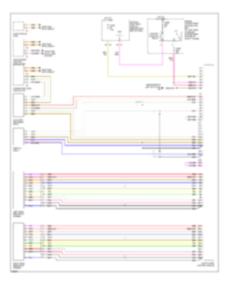
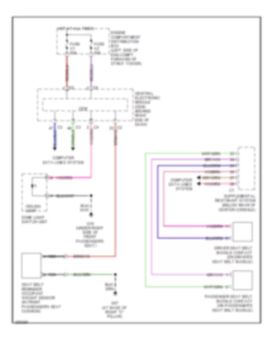
Anti-theft Wiring Diagram, Late Production for Volvo V70 2008
List of elements for Anti-theft Wiring Diagram, Late Production for Volvo V70 2008:
- Air conditioning system
- Ajar
- Cem
- Central electronic module
- Central electronic module (behind right end of dash)
- Climate control module
- Computer data lines system
- Driver's door module
- Fuse f21 5a
- Fuse f26 5a
- G10 (under right side of front passenger's seat)
- G47 (at left rear of luggage compt)
- G48 (at right rear of luggage compt)
- G95 (at left front of engine compt)
- G96 (at right front of engine compt)
- Heartbeat sensor (right rear of luggage compartment)
- Hood alarm contact (center front of engine compartment)
- Hot at all times
- Left front central locking lock motor (rear of left front door)
- Left rear central locking lock motor (rear of left rear door)
- Left rear door module
- Passenger's door module
- Red
- Right front central locking lock motor (rear of right front door)
- Right rear central locking lock motor (rear of right rear door)
- Right rear door module
- Siren control module (in right front wheelwell)
- Solar sensor, twilight sensor & indicator alarm (top center of dash)
- Tailgate lock unit
- Ultrasonic sensor (center of roof)
Forced Entry Wiring Diagram, Early Production for Volvo V70 2008
List of elements for Forced Entry Wiring Diagram, Early Production for Volvo V70 2008:
- (above left rear window) g99
- (at left rear of cargo compt) g72
- (right side of engine compt, on strut tower) g94
- A10
- A11
- A12
- A13
- Alarm siren
- B25
- C12
- C13
- C14
- Central electronic module (behind left side of dash)
- Climate control module
- Computer data lines system
- D26
- D29
- D31
- D33
- D34
- D35
- D42
- D49
- D50
- Driver door module (ddm)
- Front mass movement sensor (center front of roof)
- Fuse c6 10a
- Fuse e1 60a
- Fuse e4 50a
- Fuse e5 50a
- Fuse f8 5a
- G46 (on left rear seat riser)
- G67 (on right front seat riser)
- G72
- G93 (left side of engine compt, on strut tower)
- G98 (at front center of headliner)
- Hood alarm contact (at left front of engine compt)
- Hot at all times
- Inclination sensor module (left rear corner of vehicle)
- Key
- Left front door lock unit (rear left front door)
- Left rear door lock unit (rear of left rear door)
- Left-hand glass breakage sensor (in left rear window)
- Lock
- Lock right front door lock unit (rear of right front door)
- Main fuses (next to battery, in cargo compt)
- Passenger compartment fuse box (at left end of dash)
- Passenger door module (pdm)
- Pnk
- Rear electronic module (at left rear corner of cargo compt)
- Red
- Reduced alarm switch
- Right rear door lock unit (rear right rear door)
- Right-hand glass breakage sensor (in right rear window)
- Solar sensor, twilight sensor and indicator alarm (on top center of dash)
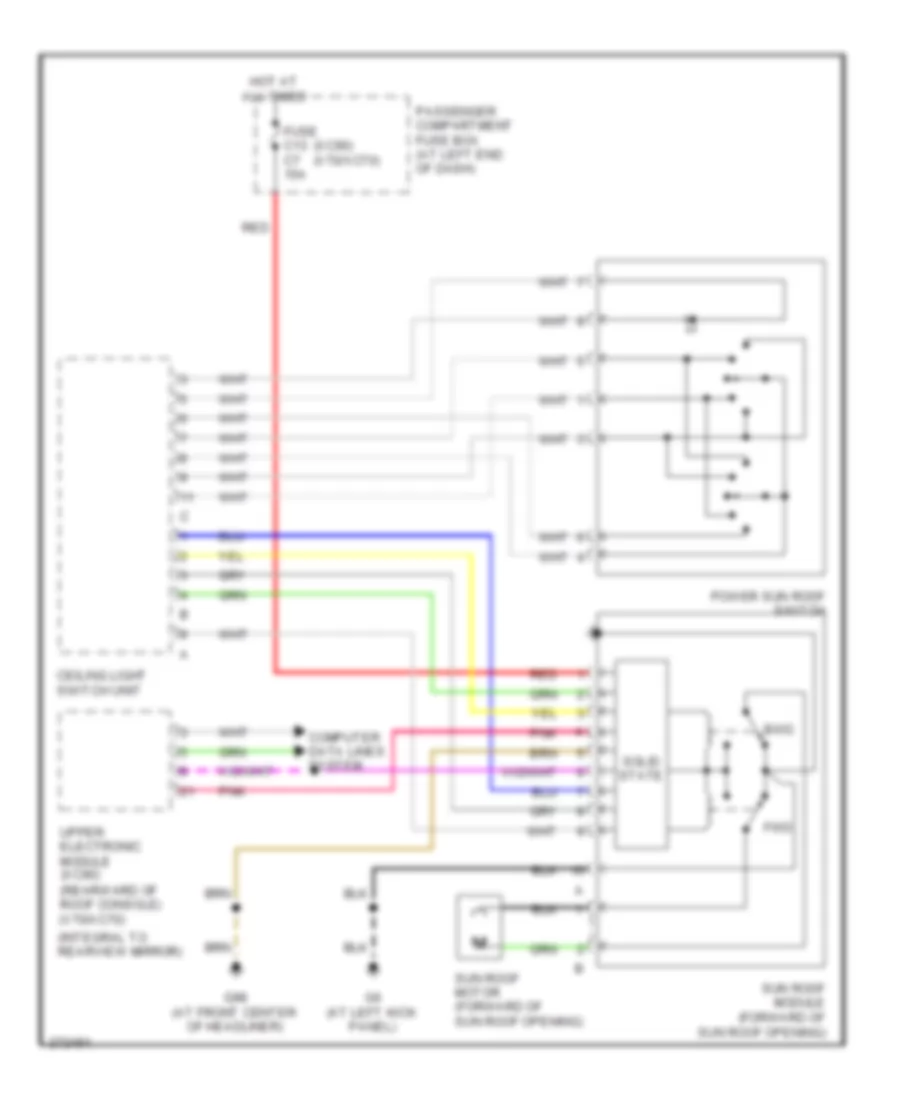
- Sunroof control module (forward of sun roof opening)
- Tailgate glass breakage sensor (in tailgate window)
- Tailgate lock unit (bottom rear of tailgate)
- Unlock
- Upper electronic module (integral to rearview mirror)
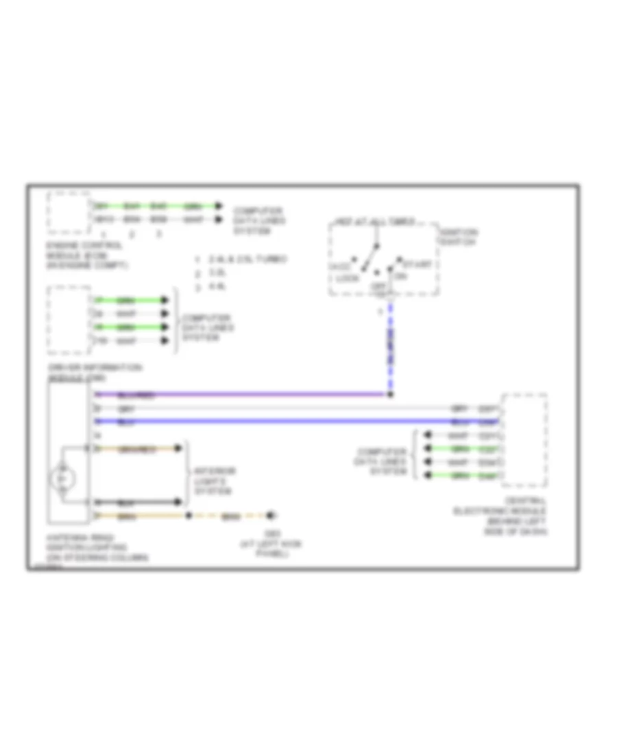
Immobilizer Wiring Diagram, Early Production for Volvo V70 2008
List of elements for Immobilizer Wiring Diagram, Early Production for Volvo V70 2008:
- 2.4l & 2.5l turbo
- 3.2l
- 4.4l
- Acc
- Antenna ring/ ignition lighting (on steering column)
- B13
- B41
- B45
- B54
- B58
- C21
- C22
- Central electronic module (behind left side of dash)
- Computer data lines system
- D34
- D49
- D56
- D57
- Driver information module (dim)
- Engine control module (ecm) (in engine compt)
- G83 (at left kick panel)
- Hot at all times
- Ignition switch
- Interior lights system
- Lock
- Off
- Start
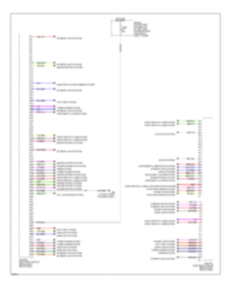
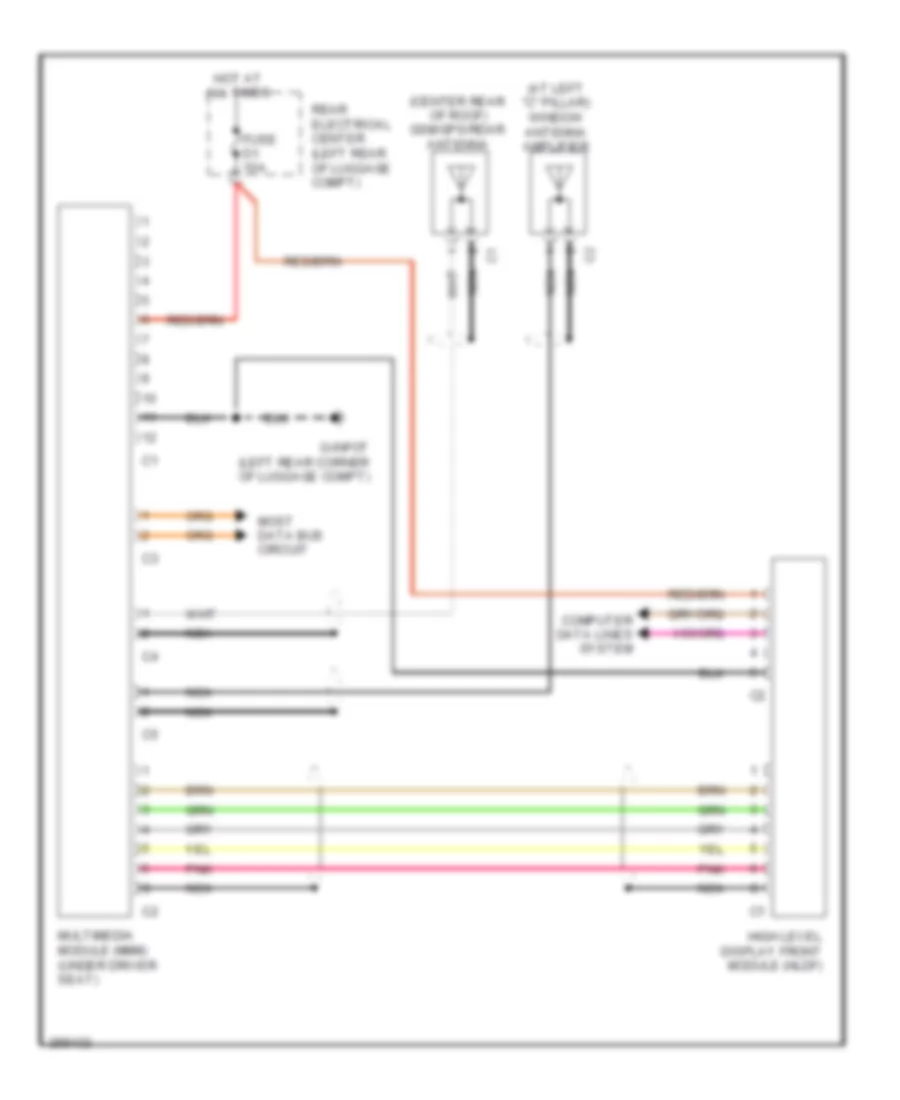
BODY CONTROL MODULES
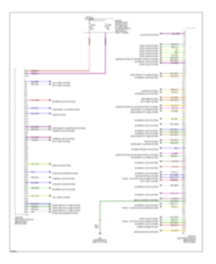
Body Control Modules Wiring Diagram, Late Production (1 of 2) for Volvo V70 2008
List of elements for Body Control Modules Wiring Diagram, Late Production (1 of 2) for Volvo V70 2008:
- Anti-lock brakes system
- Anti-theft system
- Central electronic module (behind right end of dash)
- Computer data lines & air conditioning systems
- Computer data lines system
- Cruise control system
- Door locks system
- Electronic power steering system
- Engine compartment distribution (at left side of engine compt, forward of strut tower)
- Engine controls system
- Exterior lights system
- Fuse b17 20a
- G96 (at right front of engine compt)
- Headlights system
- Horns system
- Hot in on or start
- Instrument cluster system
- Interior lights system
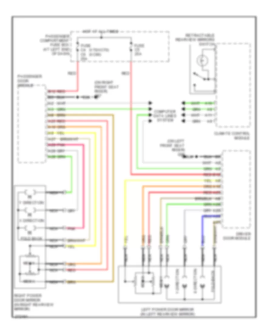
- Mirrors system
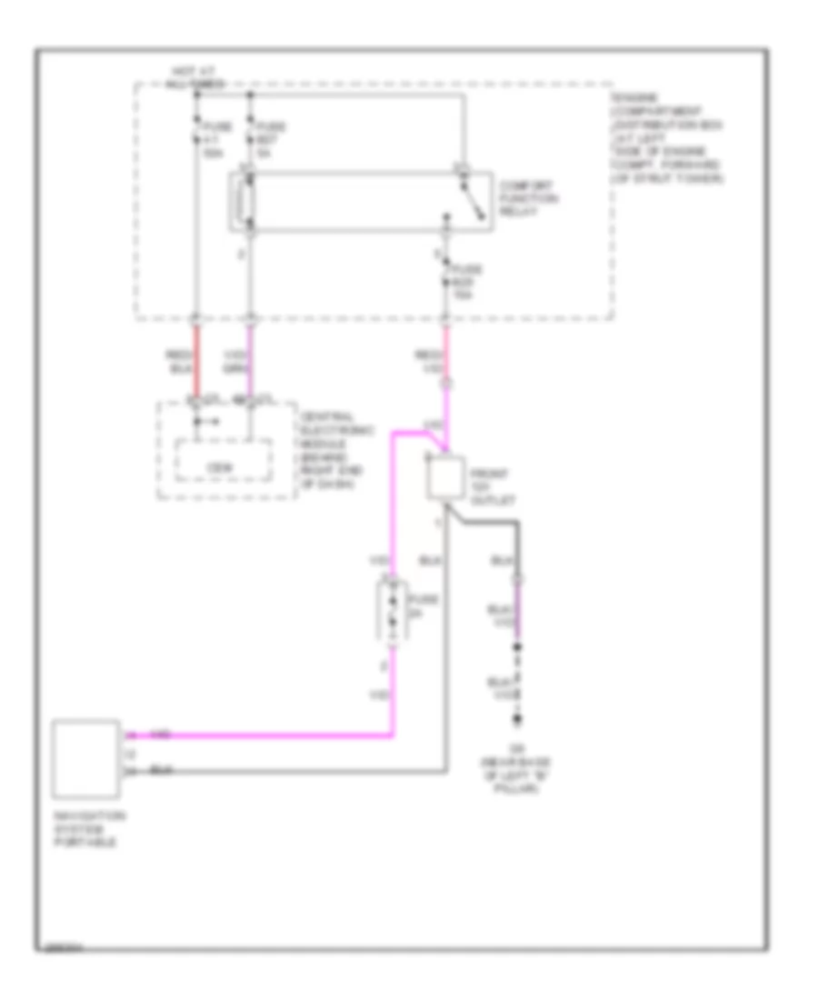
- Navigation system
- Power distribution system
- Power tops system
- Red
- Seats systems
- Sound systems
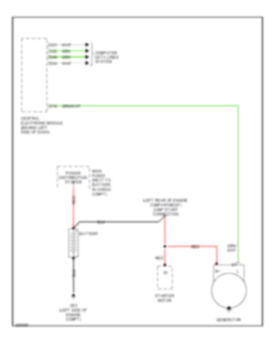
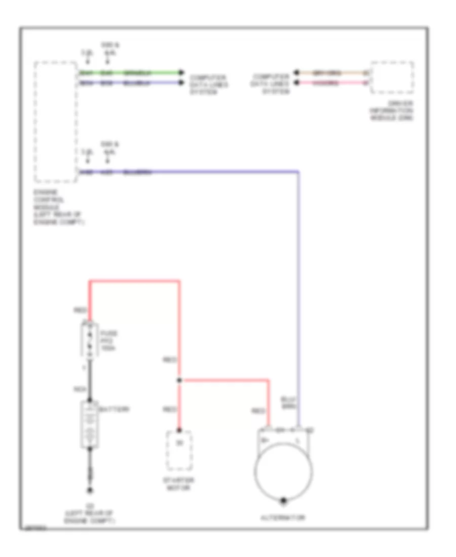
- Starting/charging system
- Wiper/washer system
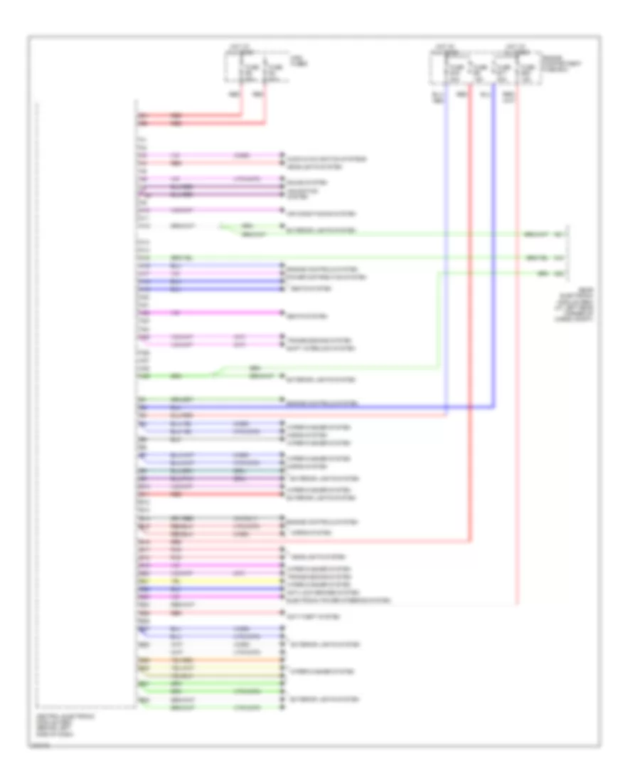
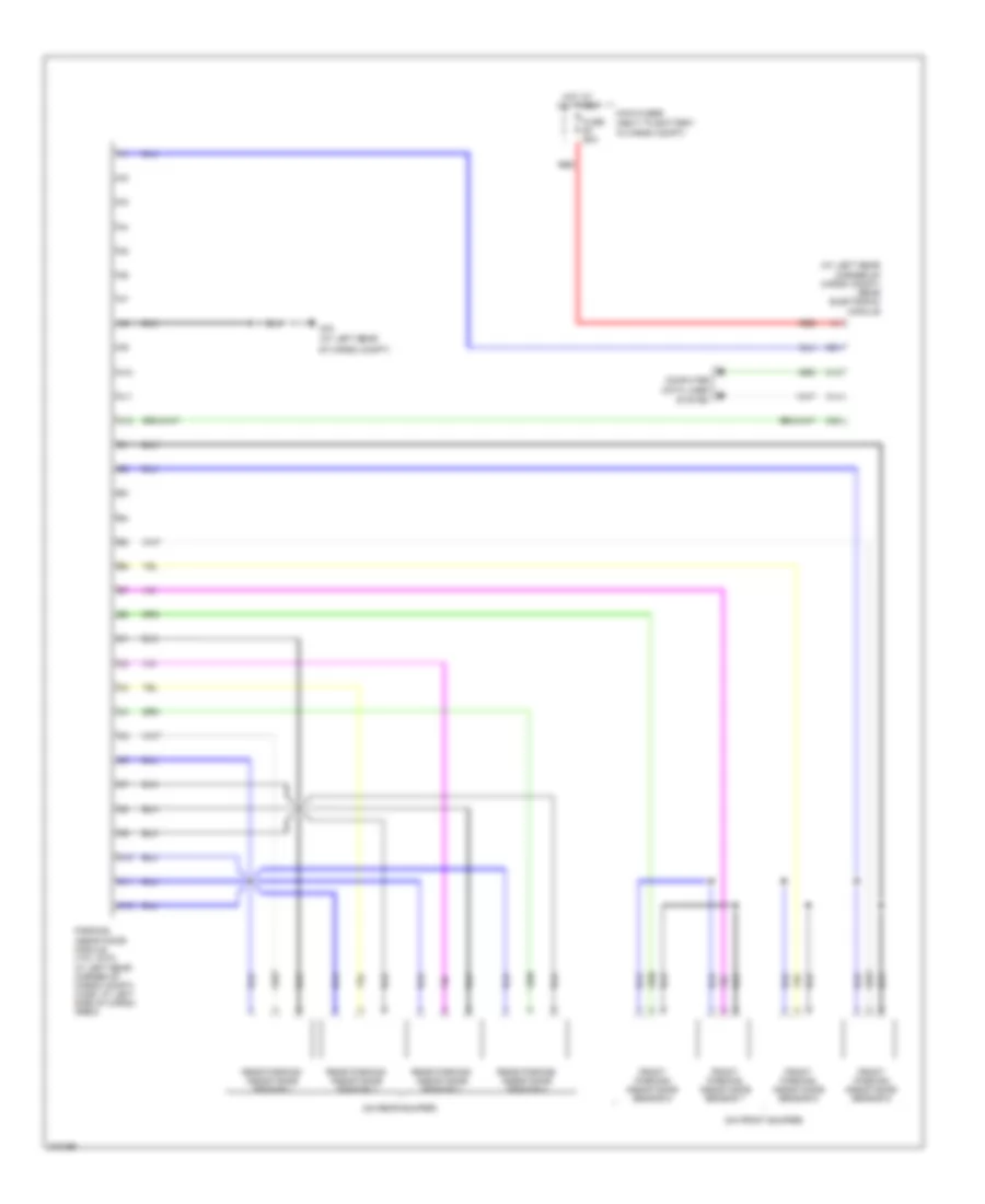
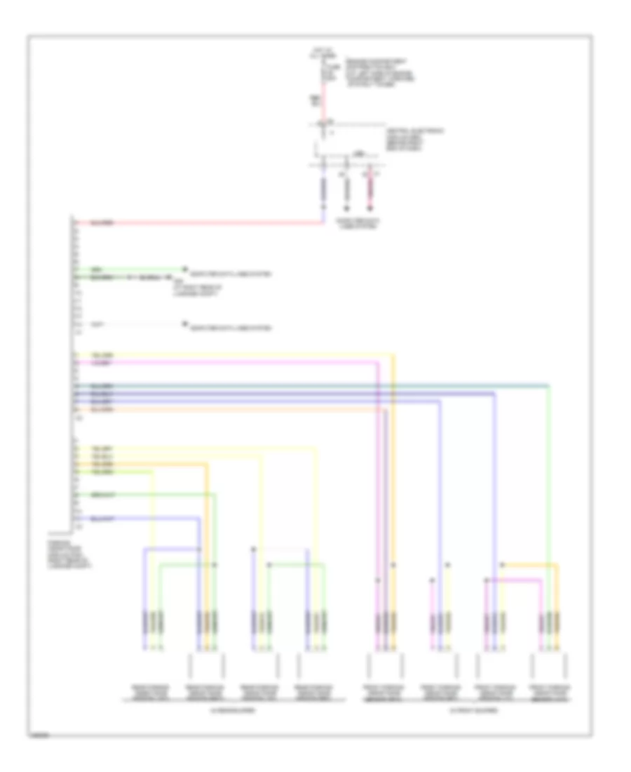
Body Control Modules Wiring Diagram, Late Production (2 of 2) for Volvo V70 2008
List of elements for Body Control Modules Wiring Diagram, Late Production (2 of 2) for Volvo V70 2008:
- Air conditioning system
- Anti-theft system
- Central electronic module (behind right end of dash)
- Computer data lines system
- Cruise control system
- Defogger system
- Door locks system
- Engine compartment distribution (at left side of engine compt, forward of strut tower)
- Engine controls & cruise control systems
- Engine controls system
- Exterior lights system
- Fuse a1 50a
- Fuse a2 50a
- G84 (near base of right "b" pillar)
- Horns system
- Hot at all times
- Instrument cluster system
- Interior lights system
- Navigation system
- Power distribution system
- Seats & memory systems
- Seats system
- Starting/charging system
- Trunk, tailgate & fuel doors system
- Warning systems
- Wiper/washer system
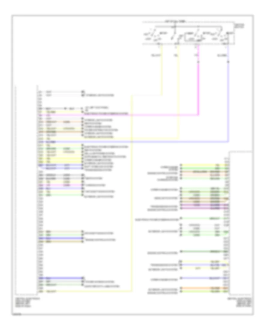
Central Electronic Module Wiring Diagram, Early Production (1 of 2) for Volvo V70 2008
List of elements for Central Electronic Module Wiring Diagram, Early Production (1 of 2) for Volvo V70 2008:
- (a/t)
- (drl)
- (m/t)
- (v70/xc70)
- (v8 only)
- (xc90)
- A10
- A11
- A12
- A13
- A14
- A15
- A16
- A17
- A18
- A19
- A20
- A21
- A22
- A23
- A24
- A25
- A26
- A27
- A28
- A29
- Air conditioning system
- Anti-lock brakes system
- Anti-theft system
- Audio & navigation systems
- B10
- B11
- B12
- B13
- B14
- B15
- B16
- B17
- B18
- B19
- B20
- B21
- B22
- B23
- B24
- B25
- B26
- B27
- B28
- B29
- B30
- B31
- B32
- Central electronic module (cem) (behind left side of dash)
- Electronic power steering system
- Engine compartment fuse box
- Engine controls system
- Exterior lights system
- Fuse b16 20a
- Fuse b17 20a
- Fuse b20 15a
- Fuse b9 15a
- Fuse e4 50a
- Fuse e5 50a
- Headlights system
- Horns system
- Hot at all times
- Main fuses
- Navigation system
- Pnk
- Power distribution system
- Rear electronic module (rem) (at left rear corner of cargo compt)
- Red
- Seats system
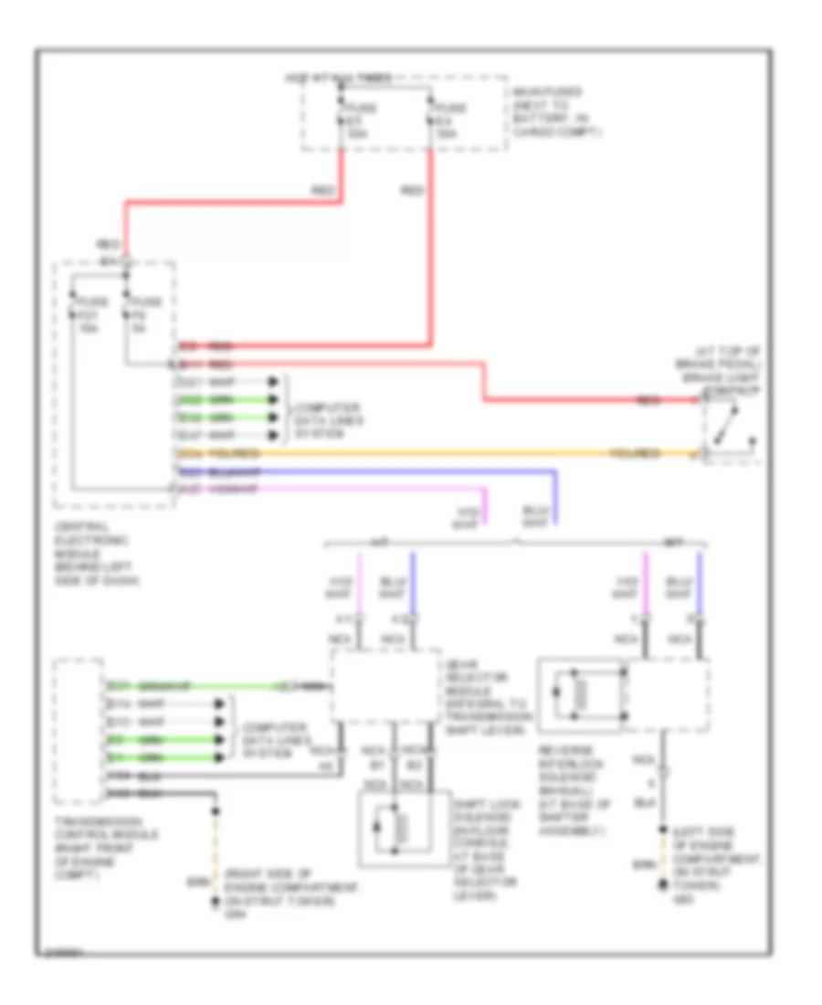
- Shift interlock system
- Sound system
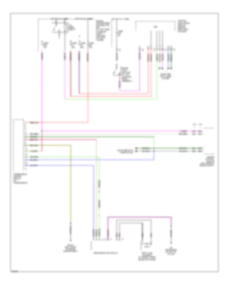
- Transmissions system
- Wiper/washer system
Central Electronic Module Wiring Diagram, Early Production (2 of 2) for Volvo V70 2008
List of elements for Central Electronic Module Wiring Diagram, Early Production (2 of 2) for Volvo V70 2008:
- (4wd)
- (a/t)
- (at left kick panel)
- (m/t)
- (v70/xc70)
- (xc90)
- 15a
- Acc
- Air conditioning system
- C10
- C11
- C12
- C13
- C14
- C15
- C16
- C17
- C18
- C19
- C20
- C21
- C22
- C23
- C24
- C25
- C26
- C27
- C28
- C29
- C30
- C31
- C32
- C33
- C34
- C35
- Cellular phones system
- Central electronic module (cem) (behind left side of dash)
- Computer data lines system
- D10
- D11
- D12
- D13
- D14
- D15
- D16
- D17
- D18
- D19
- D20
- D21
- D22
- D23
- D24
- D25
- D26
- D27
- D28
- D29
- D30
- D31
- D32
- D33
- D34
- D35
- D36
- D37
- D38
- D39
- D40
- D41
- D42
- D43
- D44
- D45
- D46
- D47
- D48
- D49
- D50
- D51
- D52
- D53
- D54
- D55
- D56
- D57
- D58
- D59
- D60
- Electronic power steering system
- Engine controls system
- Exterior lights system
- Headlights system
- Hot at all times
- Ignition switch
- Interior lights system
- Key in
- Lock
- Off
- Power antenna system
- Power distribution system
- Seats system
- Shift interlock system
- Start
- Starting/ charging system
- Transmissions system
- Warning system
- Wiper/washer system
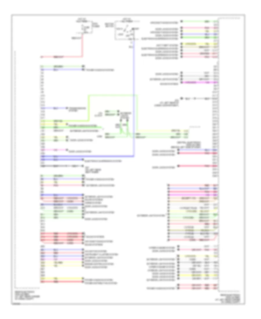
Rear Electronic Module Wiring Diagram, Early Production for Volvo V70 2008
List of elements for Rear Electronic Module Wiring Diagram, Early Production for Volvo V70 2008:
- (13 pole)
- (13 pole/7 pole)
- (7 pole)
- (except v70)
- (v70/xc70)
- (v70/xc90)
- (xc90)
- 15l
- A10
- A11
- A12
- A13
- A14
- A15
- A16
- A17
- A18
- A19
- A20
- A21
- A22
- A23
- A24
- A25
- A26
- A27
- A28
- A29
- A30
- A31
- A32
- Acc
- Air conditioning system
- Anti-theft system
- B10
- B11
- B12
- B13
- B14
- B15
- B16
- B17
- B18
- B19
- B20
- B21
- B22
- B23
- B24
- B25
- B26
- B27
- B28
- B29
- B30
- B31
- C10
- C11
- C12
- Central electronic module (cem) (behind left side of dash)
- D10
- D11
- D12
- D13
- D14
- D15
- D16
- D17
- D18
- D19
- D20
- D21
- D22
- D23
- D24
- D25
- D26
- D27
- D28
- D29
- D3 d1
- D30
- D31
- D32
- D33
- D34
- D35
- D36
- Door locks system
- Electronic suspension system
- Engine controls system
- Exterior lights system
- F10
- Fuse e1 60a
- G47 (on left rear seat riser)
- G72 (at left rear of cargo compartment)
- Horns system
- Hot at all times
- Ignition switch
- Instrument cluster system
- Interior lights system
- Lock
- Main fuses
- Navigation system
- Off
- Pnk
- Power distribution system
- Power windows system
- Rear electronic module (rem) (at left rear corner of cargo compt)
- Red
- Sound systems
- Start
- Transmissions system
- V70 & xc70
- Wiper/washer system
- Xc90
COMPUTER DATA LINES
Computer Data Lines Wiring Diagram, Early Production (1 of 2) for Volvo V70 2008
List of elements for Computer Data Lines Wiring Diagram, Early Production (1 of 2) for Volvo V70 2008:
- (under driver's seat) headlight control module
- (w/ 2wd, w/ hcm)
- (w/ 2wd, w/o hcm)
- (w/ awd)
- (w/ awd, w/o four-c, w/o hcm)
- (w/ four-c)
- (w/ hcm, w/ awd, w/four-c)
- (w/ hcm, w/o four-c)
- A15
- A16
- Alternator
- B23
- B24
- B25
- B26
- Body sensor cluster (bsc) (dynamic stability traction) (under front passenger's seat)
- Brake control module (bcm) (at left rear
- C16
- C21
- C22
- C32
- Central electronic module (behind left side of dash)
- Combustion preheater module (cpm)
- Corner of engine compt)
- D24
- D31
- D32
- D33
- D34
- D35
- D36
- D37
- D38
- D39
- D40
- D41
- D46
- D47
- D48
- D49
- D50
- D51
- D52
- D53
- D54
- D55
- D58
- Data link connector (dlc) (under left side of dash)
- Differential electronic module (awd) (at rear differential)
- Driver door module (ddm)
- Fuse c9 5a
- G84 (at right kick panel)
- Hot at all times
- Lights switch unit (lsm)
- Nca
- Occupant weight sensor (ows) (under front passenger's seat)
- Passenger compartment fuse box (at left end of dash)
- Pnk
- Rain sensor module (rsm) (top center of windshield)
- Red
- Siren control module (scm)
- Steering angle sensor module
- Steering wheel module (swm)
- Sunroof module (srm) (forward of sun roof opening)
- Suspension module (sum) (four-c) (under center console)
- Upper electronic module (uem) (integral to rearview mirror)
- W/o sunroof
Computer Data Lines Wiring Diagram, Early Production (2 of 2) for Volvo V70 2008
List of elements for Computer Data Lines Wiring Diagram, Early Production (2 of 2) for Volvo V70 2008:
- (in left power door mirror) left camera module
- (in right power door mirror) right camera module
- A10
- A11
- A12
- A37
- A55
- Accessory electronic module (aem) (at right rear corner of cargo compt)
- Air quality sensor (aqs) (at right side of plenum)
- Audio module (aum) (under right front seat)
- Automatic transmission mode selector
- B13
- B14
- B21
- C13
- C14
- Climate control module (ccm)
- D19
- D20
- D21
- D26
- D30
- D32
- Damper motor module (dmm) (on hvac housing)
- Damper motor module (on hvac housing)
- Driver information module (dim)
- Electronic throttle module (etm) (gasoline) (front of engine compt)
- Engine control module (ecm) (in engine compt)
- Gear selector module (gsm)
- Inclination sensor module (ism) (left rear of vehicle)
- Left front lamp housing
- Left seat heater module (shm) (under left front seat)
- Nca
- Parking assistance module (pam) (at left rear corner of cargo compt)
- Passenger door module (pdm)
- Phone module (phm)
- Power seat module (psm) (under driver's seat)
- Rear electronic module (rem) (at left rear corner of cargo compt)
- Right front lamp housing
- Right seat heater module (shm) (under right front seat)
- Road traffic information module (rti) (left rear side of luggage compt)
- Transmission control module (tcm) (automatic) (at right front of engine compt)
Computer Data Lines Wiring Diagram, Late Production (1 of 2) for Volvo V70 2008
List of elements for Computer Data Lines Wiring Diagram, Late Production (1 of 2) for Volvo V70 2008:
- Bus 1
- Bus 2
- Bus 3
- Cem
- Central electronic module (cem) (behind right end of dash)
- Climate control module
- Combustion preheater module
- Data link connector (dlc) (under left end of dash)
- Driver information module
- Driver's door module (in left front door)
- Forward aimed radar (behind center of grille)
- Forward sensing module (behind right side of dash)
- Fuse f26 5a
- G10 (under right side of front passnger's seat)
- G83 (under driver's door sill)
- Heartbeat sensor (right rear of luggage compartment)
- High
- High level display front module
- Hot at all times
- Infotainment control module
- Keyless vehicle module (right side of luggage compartment)
- Light switch module
- Lin
- Mid
- Mid mid
- Parking assistance module (right rear of luggage compartment)
- Passenger's door module (in right front door)
- Phone module
- Power seat module
- Rain sensor module (forward of inside rearview mirror)
- Red
- Remote keyless entry/remote receiver module (center rear of roof/behind left side of dash)
- Right front suspension height sensor (in right front of roof)
- Steering wheel module (in steering column)
- Trailer module (left rear of trunk)
Computer Data Lines Wiring Diagram, Late Production (2 of 2) for Volvo V70 2008
List of elements for Computer Data Lines Wiring Diagram, Late Production (2 of 2) for Volvo V70 2008:
- 3.2l
- 4.4l
- A25
- A92
- Alternator control module (in alternator)
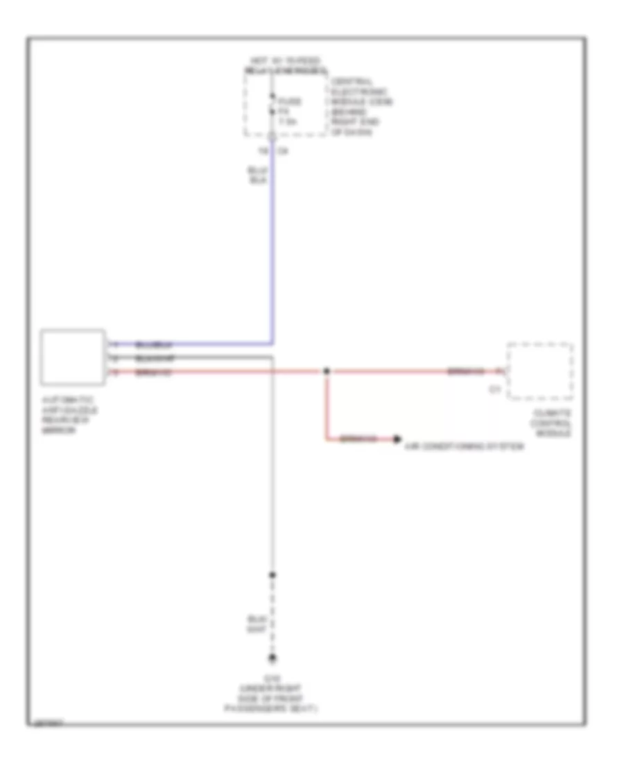
- Automatic anti-dazzle rearview mirror
- B41
- B45
- B54
- B58
- Body sensor cluster stability sensor (under front passenger's seat)
- Brake control module (at left rear of engine compartment)
- Climate control system (damper motor modules)
- Differential electronic module (on differential)
- Engine control module (ecm) (left rear of engine compartment)
- Front door power window switch
- Gear selector module
- Headlamp control module (right rear of engine compartment)
- Heated rear seats switch
- High
- Left camera module (integral to left outside rear view mirror)
- Left front seat heating module (in left front seat bottom)
- Left rear door module (in left rear door)
- Left rear seat heater control module (under left rear seat)
- Lin
- Mid
- Occupant weight sensor (in front passenger's seat cushion)
- Parking brake module (left side of trunk)
- Power operated tailgate module (v70)
- Right camera module (integral to right outside rear view mirror)
- Right front seat heating module (in right front seat bottom)
- Right rear door module (in right rear door)
- Right rear seat heater control module (under right rear seat)
- Siren control module (in right front wheelwell)
- Start control unit (behind left side of dash)
- Steering column lock module (on steering column)
- Suspension module (sum) (behind center of rear seats)
- Transmission control module (tcm) (on transmission)
- Wiper motor module (at left rear of engine compartment)
COOLING FAN
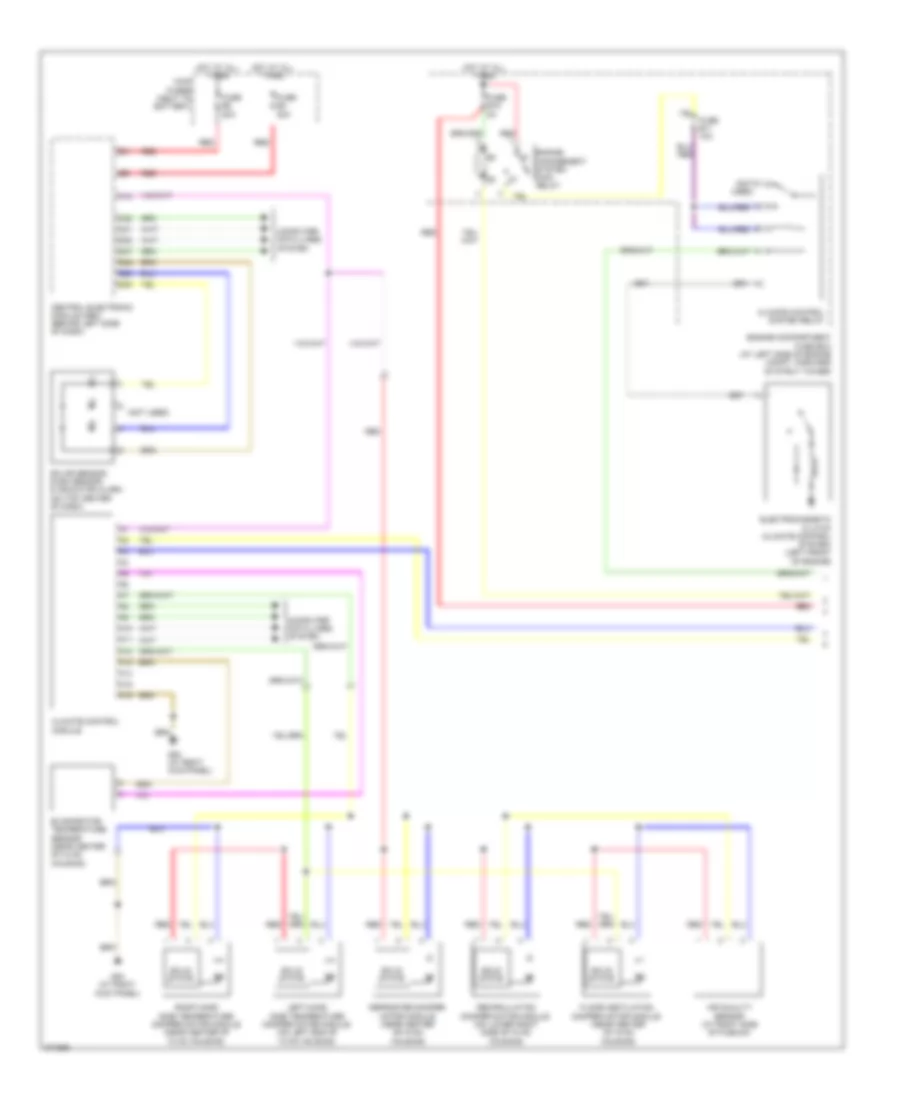
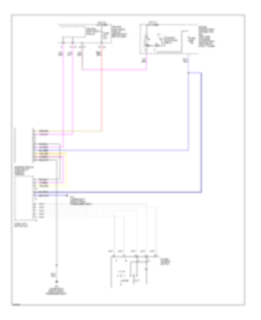
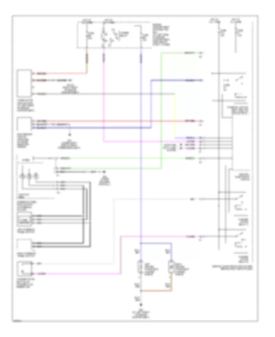
Cooling Fan Wiring Diagram, Early Production for Volvo V70 2008
List of elements for Cooling Fan Wiring Diagram, Early Production for Volvo V70 2008:
- (at front center of engine compt) cooling fan module
- (front of engine compt) cooling fan motor
- (left side of engine compt) c54/1b
- 2.4l
- 2.5l turbo
- A21
- A39
- A40
- A58
- A60
- A61
- A68
- B13
- Climate control system pressure sensor (at right front of engine compt)
- Computer data lines system
- Coolant temperature sensor (left front of engine)
- Engine compartment distribution box (left side of engine compt)
- Engine control module (ecm) (in engine compt)
- Fuse a2 60a
- G2 (in engine compt, on left strut tower)
- Hot at all times
- Nca
- Red
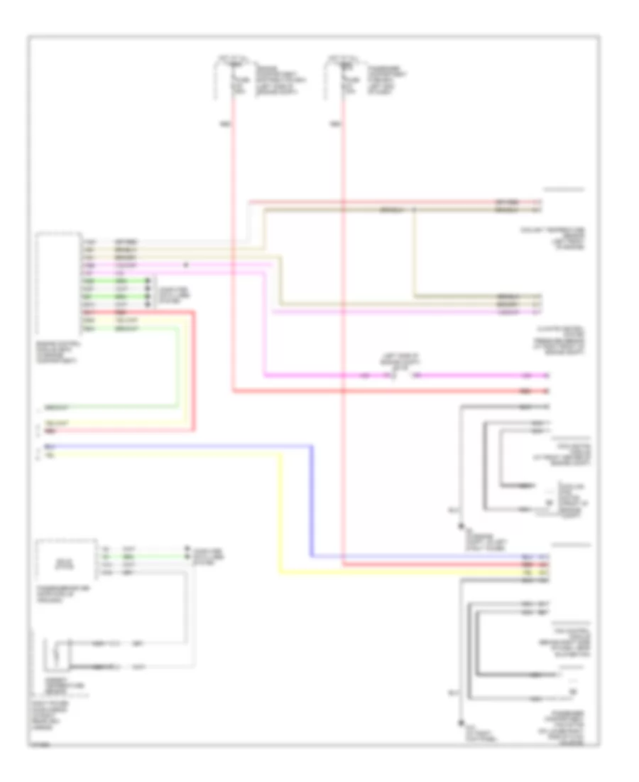
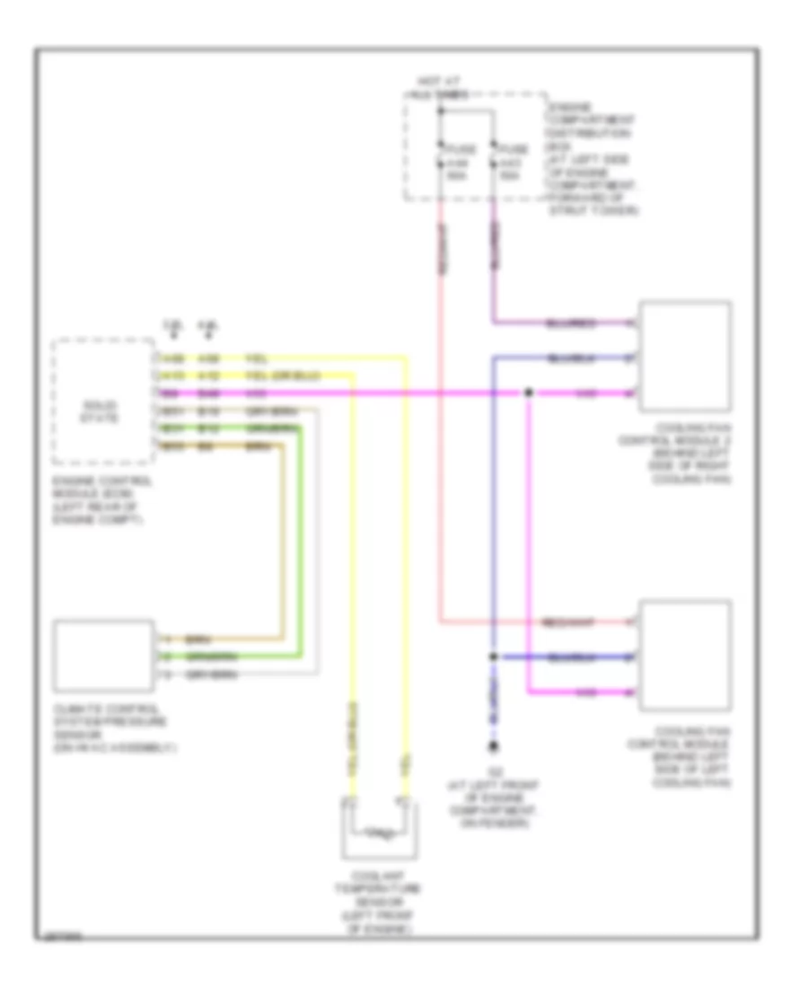
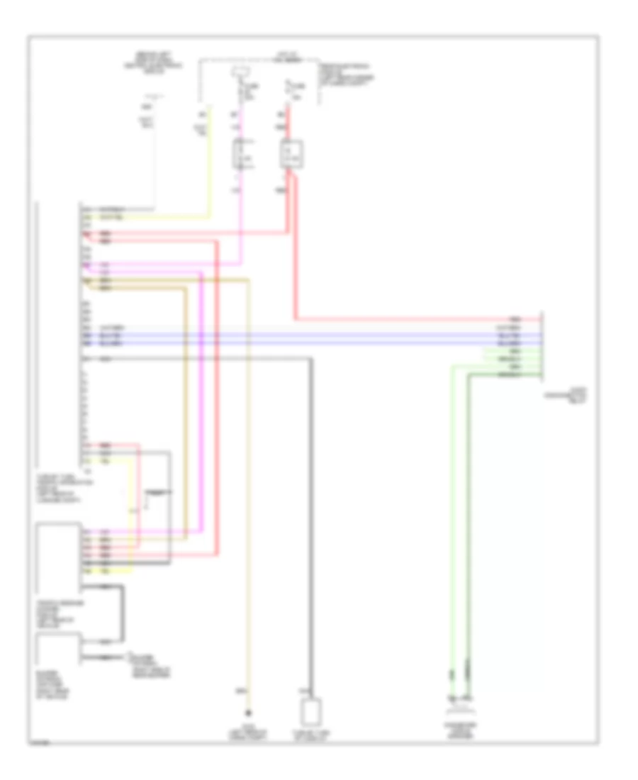
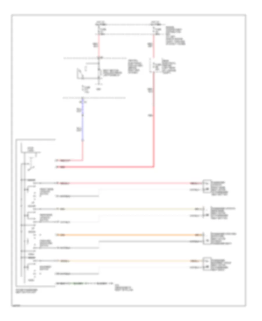
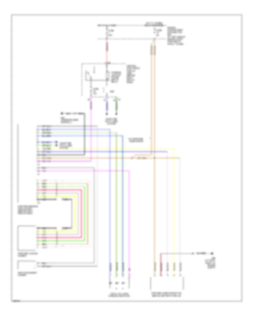
Cooling Fan Wiring Diagram, Late Production for Volvo V70 2008
List of elements for Cooling Fan Wiring Diagram, Late Production for Volvo V70 2008:
- 3.2l
- 4.4l
- A12
- A13
- A68
- B12
- B19
- B31
- B49
- B51
- B53
- Climate control system pressure sensor (on hvac assembly)
- Coolant temperature sensor (left front of engine)
- Cooling fan control module (behind left side of left cooling fan)
- Cooling fan control module 2 (behind left side of right cooling fan)
- Engine compartment distribution box (at left side of engine compartment, forward of strut tower)
- Engine control module (ecm) (left rear of engine compt)
- Fuse a43 50a
- Fuse a44 60a
- G2 (at left front of engine compartment, on fender)
- Hot at all times
- Solid state
CRUISE CONTROL
Cruise Control Wiring Diagram, Early Production for Volvo V70 2008
List of elements for Cruise Control Wiring Diagram, Early Production for Volvo V70 2008:
- (near accelerator pedal) accelerator pedal sensor
- (top of steering column) contact reel
- 2.4l
- 2.5l turbo
- A19
- A20
- A25
- A35
- A36
- A43
- A59
- B11
- B13
- B15
- B17
- B25
- B38
- Brake control module (at left rear corner of engine compt)
- Brake pedal sensor (at left rear corner of engine compt)
- Central electronic module (behind left side of dash)
- Clutch pedal sensor (behind left side of dash)
- Computer data lines system
- D58
- Engine
- Engine compartment distribution box (left side of engine compt)
- Engine control module (in engine compt)
- Engine throttle body
- Fuse b11 10a
- Fuse b19 5a
- G93 (left side of engine compt, on strut tower)
- Hot at all times
- Left front abs sensor (behind left front wheel, on spindle/hub assembly)
- Management system main relay
- Nca
- Red
- Right front abs sensor (behind right front wheel, on spindle/hub assembly)
- Steering wheel module
- Steering wheel switch left
Cruise Control Wiring Diagram, Late Production for Volvo V70 2008
List of elements for Cruise Control Wiring Diagram, Late Production for Volvo V70 2008:
- A14
- A17
- A48
- A65
- A67
- A73
- A74
- A75
- Accelerator pedal sensor (top of accelerator pedal assembly)
- B13
- B16
- B26
- B27
- B41
- B54
- Brake control module (at left rear of engine compt)
- Brake light contact (at top of brake pedal assembly)
- Brake light diagnostic contact (at top of brake pedal assembly)
- Brake pedal sensor (left rear of engine compt)
- Cem
- Central electronic module (cem) (behind right end of dash)
- Clutch pedal sensor (3.2l m/t) (at top of clutch pedal assembly)
- Computer data lines system
- Driver information module
- Electronic throttle actuator (on throttle body)
- Engine compartment distribution box (at left side of engine compartment, forward of strut tower)
- Engine control module (left rear of engine compt)
- Engine management system main relay
- Forward sensing module
- Forward-aimed radar
- Fuse b30 10a
- Fuse b36 10a
- Fuse f28 5a
- Fuse f4 7.5a
- Fuse f7 7.5a
- G7 (near base of left "b" pillar)
- G83 (under driver's door sill)
- Gear selector module
- Hot at all times
- Hot w/ 15-feed relay energized
- Left front abs sensor (on left hub assembly)
- Left steering wheel switch
- Nca
- Right front abs sensor (on right hub assembly)
- Right steering wheel switch
- Steering wheel module (in steering column)
- Transmission control module (on transmission)
- V70
- Xc70
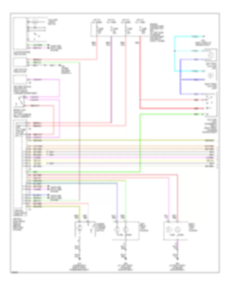
DEFOGGERS
Heated Mirrors Wiring Diagram, Early Production for Volvo V70 2008
List of elements for Heated Mirrors Wiring Diagram, Early Production for Volvo V70 2008:
- (v70/xc70) (xc90)
- A10
- A11
- B10
- B11
- B12
- Climate control module
- Computer data lines system
- Driver door control module (ddm)
- Fuse c4 c6 25a
- Fuse c5 25a
- G66 (on left front seat riser)
- G67 (on right front seat riser)
- Heated rear window/rearview mirrors switch
- Hot at all times
- Interior lights system
- Left power door mirror (in left rearview mirror)
- Mirror heating element
- Nca
- Passenger compartment fuse box (at left end of dash)
- Passenger door control module (pdm)
- Red
- Right power door mirror (in right rearview mirror)
- Xc90
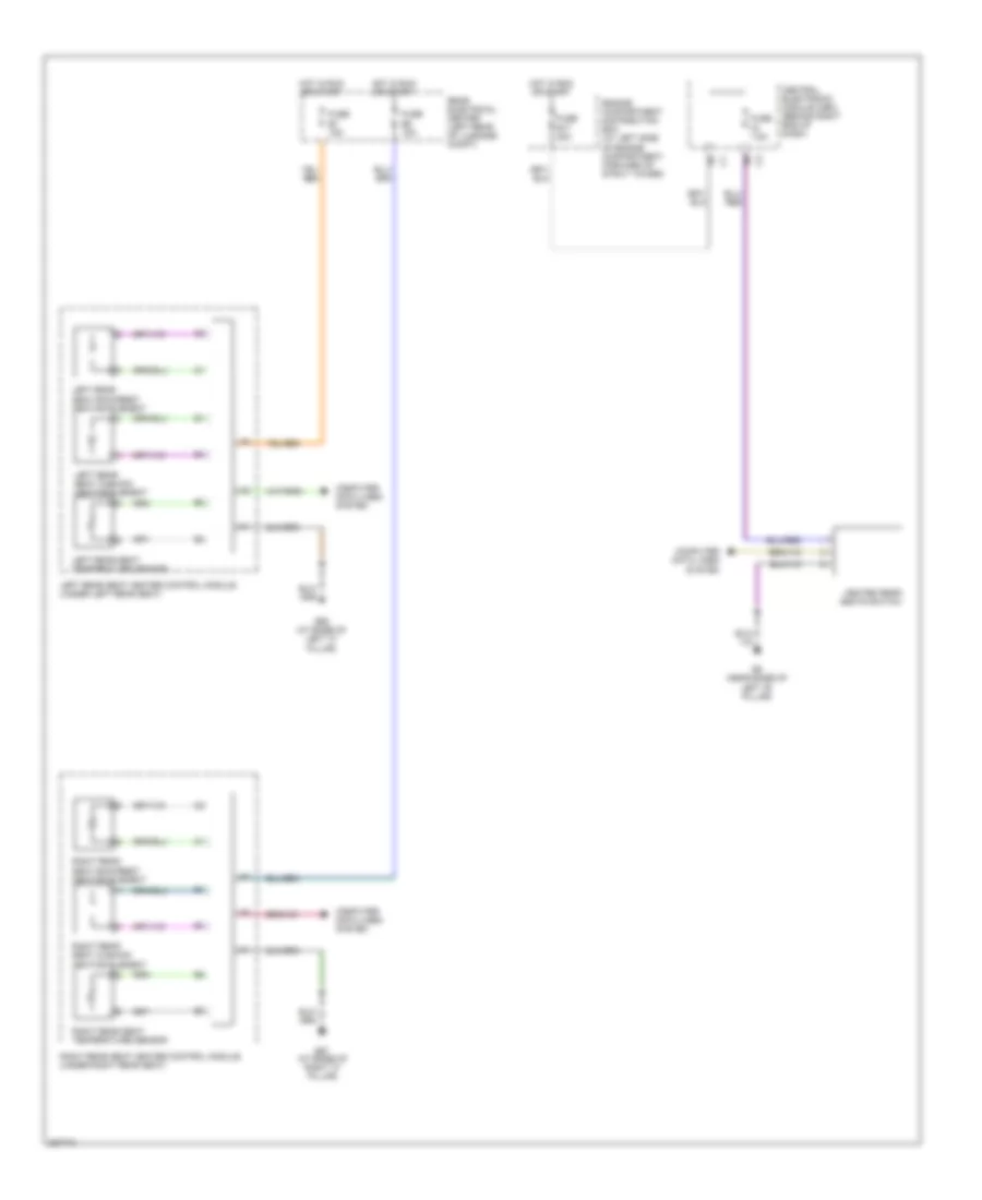
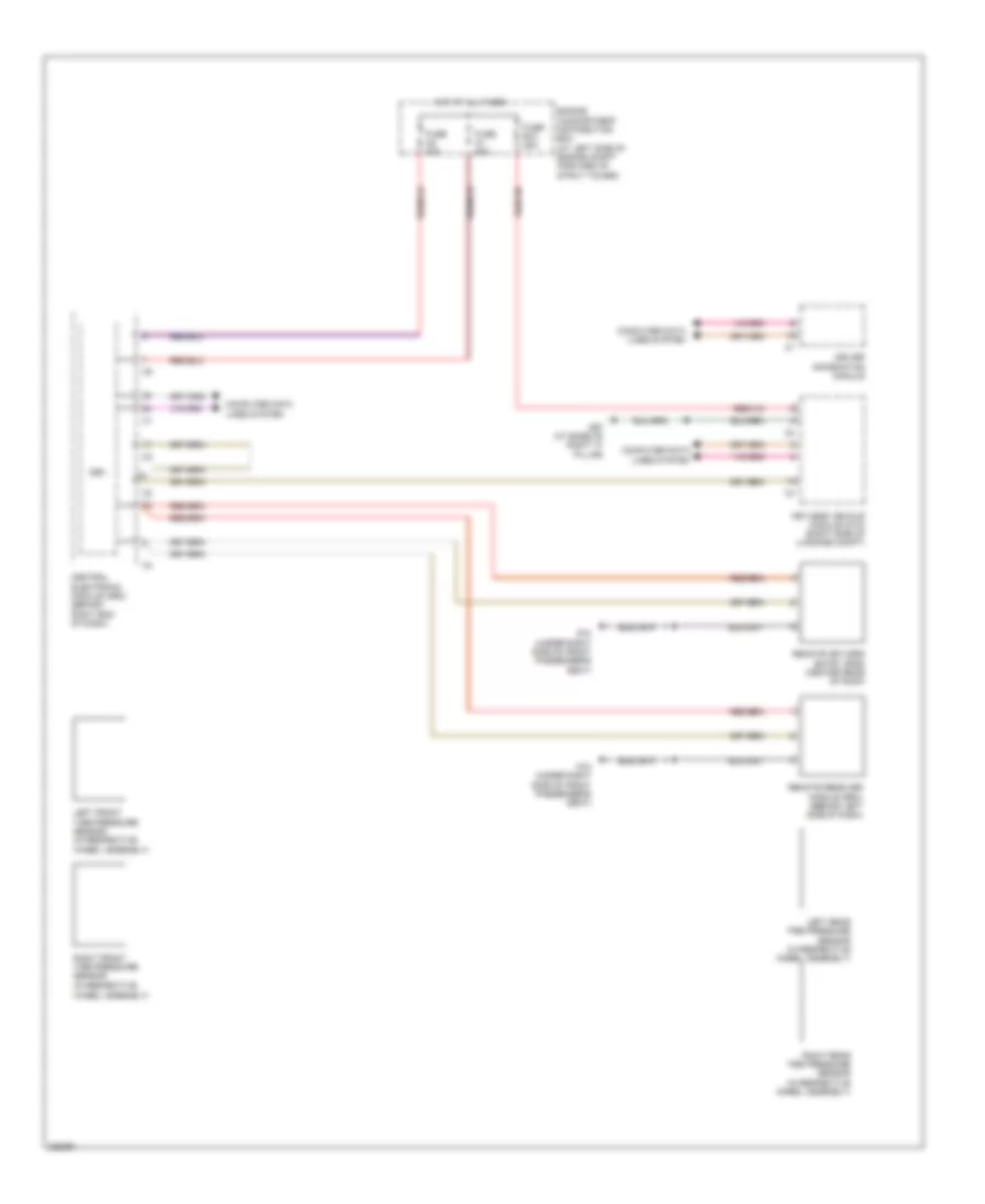
Heated Mirrors Wiring Diagram, Late Production for Volvo V70 2008
List of elements for Heated Mirrors Wiring Diagram, Late Production for Volvo V70 2008:
- Central electronic module
- Central electronic module (behind right end of dash)
- Climate control module
- Computer data line system
- Computer data lines system
- Driver's door module (in respective front door)
- Front door power window switch
- Fuse a1 25a
- Fuse a2 25a
- Fuse f17 7.5a
- G15 (near base of right 'b' pillar)
- G6 (near base of left 'b' pillar)
- Hot at all times
- Left power door mirror
- Mirror defroster
- Passenger's door module (in respective front door)
- Rear electrical center (left rear of luggage compartment)
- Rear window/ door mirror defroster switch
- Red
- Right power door mirror
- Seat heating module, interior lighting relay
- W/ keyless
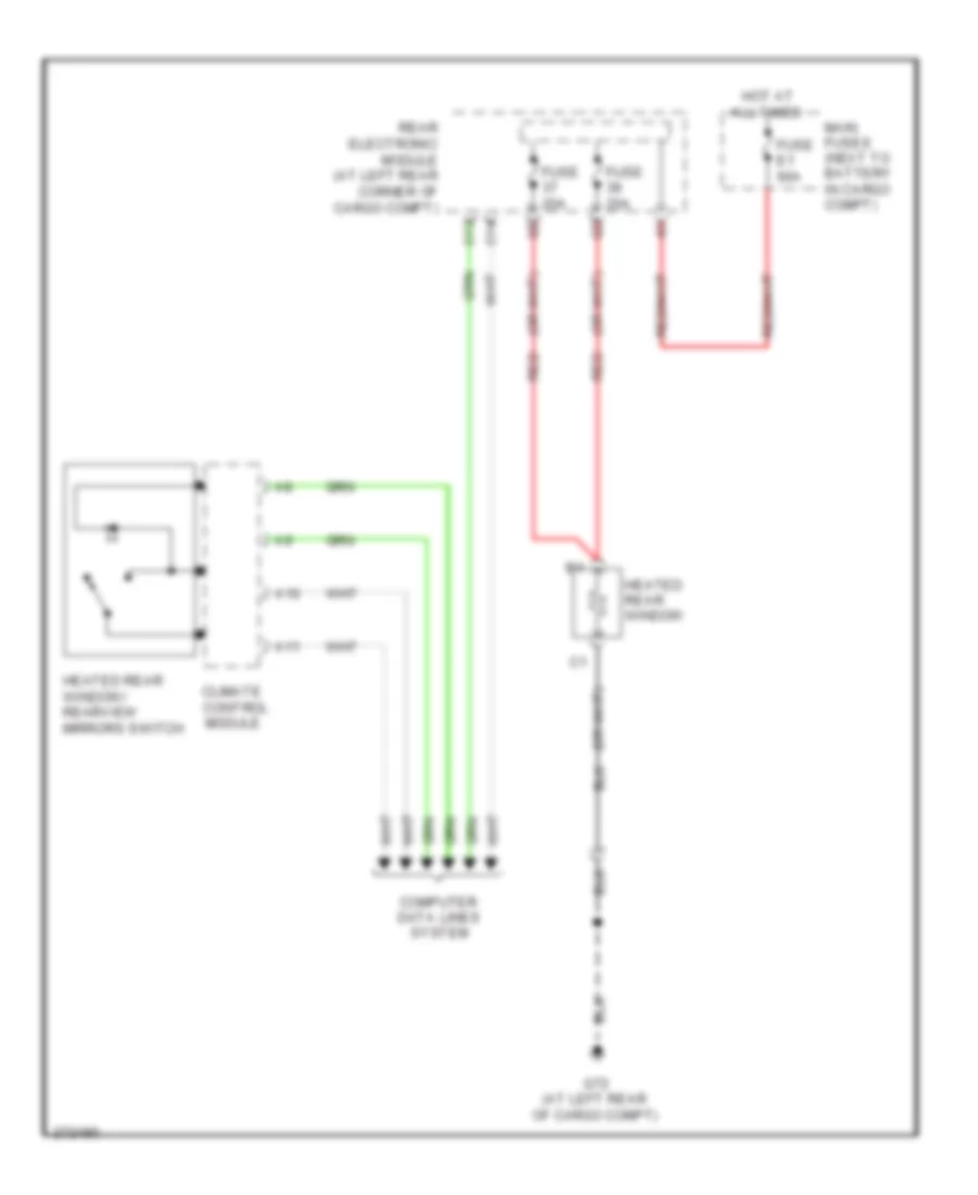
Rear Defogger Wiring Diagram, Early Production for Volvo V70 2008
List of elements for Rear Defogger Wiring Diagram, Early Production for Volvo V70 2008:
- A10
- A11
- C13
- C14
- Climate
- Computer data lines system
- Control
- Fuse 20a
- Fuse e1 60a
- G72 (at left rear of cargo compt)
- Heated rear window
- Heated rear window/ rearview mirrors switch
- Hot at all times
- Main fuses (next to battery in cargo compt)
- Module
- Rear electronic module (at left rear corner of cargo compt)
- Red
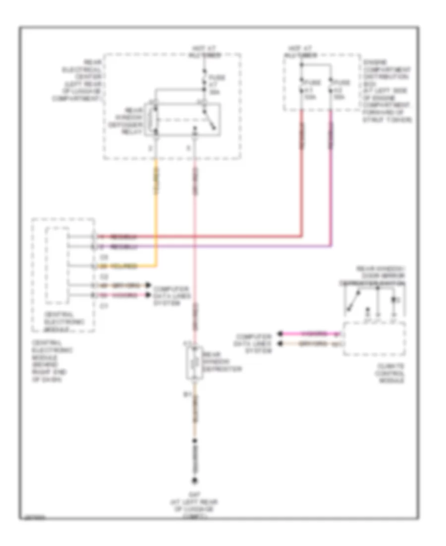
Rear Defogger Wiring Diagram, Late Production for Volvo V70 2008
List of elements for Rear Defogger Wiring Diagram, Late Production for Volvo V70 2008:
- Central electronic module
- Central electronic module (behind right end of dash)
- Climate control module
- Computer data lines system
- Engine compartment distribution box (at left side of engine compartment, forward of strut tower)
- Fuse a1 50a
- Fuse a2 50a
- Fuse a7 30a
- G47 (at left rear of luggage compt)
- Hot at all times
- Rear electrical center (left rear of luggage compartment)
- Rear window defogger relay
- Rear window defroster
- Rear window/ door mirror defroster switch
ELECTRONIC POWER STEERING
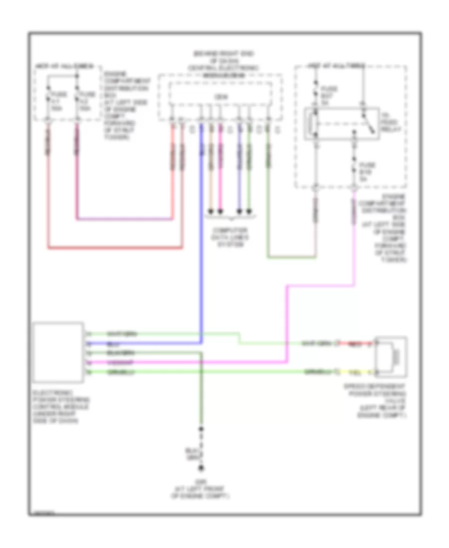
Electronic Power Steering Wiring Diagram, Early Production for Volvo V70 2008
List of elements for Electronic Power Steering Wiring Diagram, Early Production for Volvo V70 2008:
- A37
- A55
- B13
- B23
- Brake control module (bcm) (at left rear corner of engine compt)
- C17
- C21
- C22
- Central electronic module (cem) (behind left side of dash)
- Computer data lines system
- D34
- D49
- Driver information module (dim)
- Electronic power steering control module (left center of dash)
- Engine control module (ecm) (in engine compt)
- Fuse 10a
- Fuse e4 50a
- G93 (left side of engine compt, on strut tower)
- Hot at all times
- Main fuses (next to battery in cargo compartment)
- Nca
- Red
- Speed dependent power steering valve
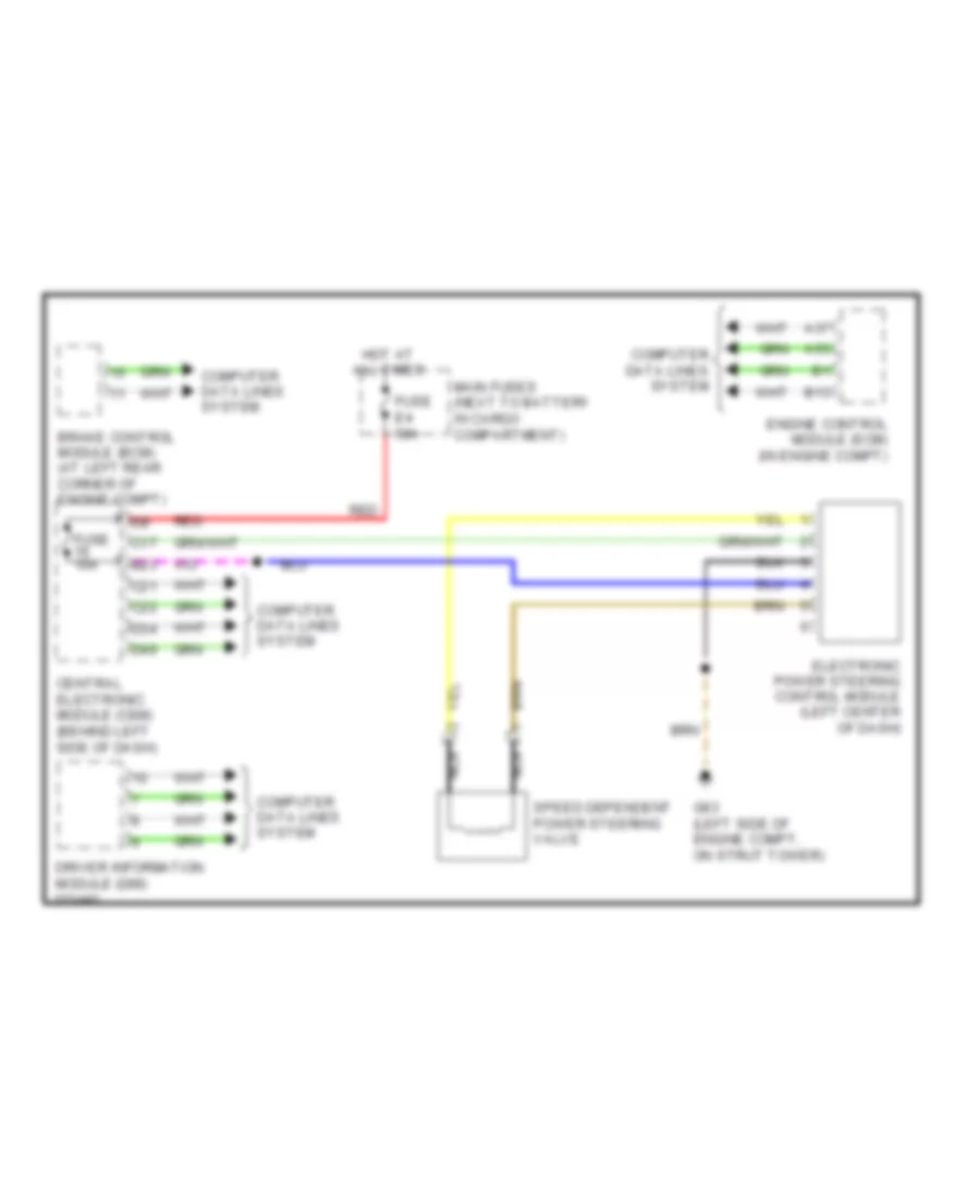
Electronic Power Steering Wiring Diagram, Late Production for Volvo V70 2008
List of elements for Electronic Power Steering Wiring Diagram, Late Production for Volvo V70 2008:
- (behind right end of dash) central electronic module(cem)
- 15- feed relay
- Cem
- Computer data lines system
- Electronic power steering control module (under right side of dash)
- Engine compartment distribution box (at left side of engine compt, forward of strut tower)
- Fuse a1 50a
- Fuse a2 50a
- Fuse b19 5a
- Fuse b27 5a
- G95 (at left front of engine compt)
- Hot at all times
- Red
- Speed dependent power steering valve (left rear of engine compt)
ENGINE PERFORMANCE
2.4L
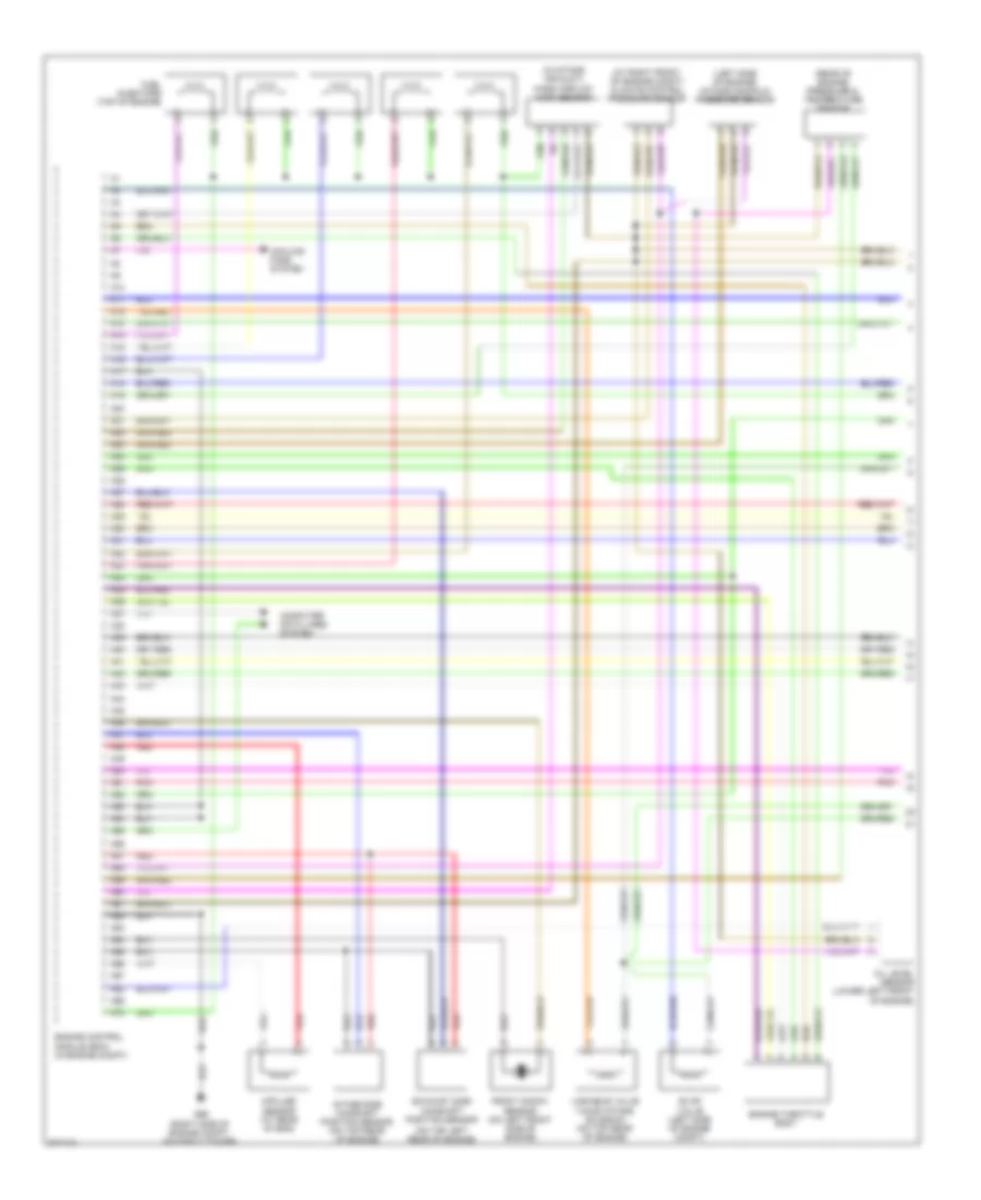
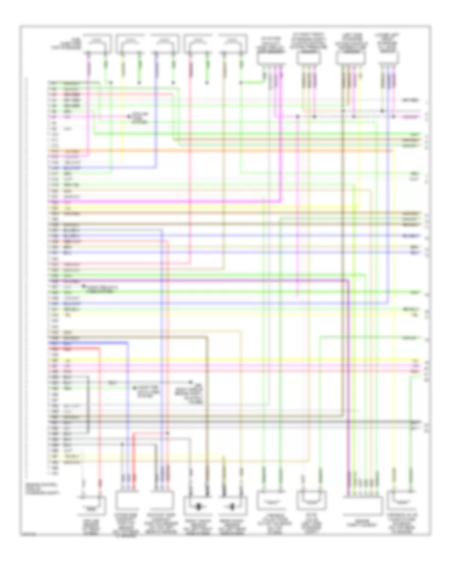
2.4L, Engine Performance Wiring Diagram, Early Production (1 of 3) for Volvo V70 2008
List of elements for 2.4L, Engine Performance Wiring Diagram, Early Production (1 of 3) for Volvo V70 2008:
- (at right front of engine compt) climate control pressure sensor
- (in intake air duct)
- (left side of engine) intake manifold pressure sensor
- (on top left rear of engine)
- (rear of engine) pressure & temperature sensor
- A10
- A11
- A12
- A13
- A14
- A15
- A16
- A17
- A18
- A19
- A20
- A21
- A22
- A23
- A24
- A25
- A26
- A27
- A28
- A29
- A30
- A31
- A32
- A33
- A34
- A35
- A36
- A37
- A38
- A39
- A40
- A41
- A42
- A43
- A44
- A45
- A46
- A47
- A48
- A49
- A50
- A51
- A52
- A53
- A54
- A55
- A56
- A57
- A58
- A59
- A60
- A61
- A62
- A63
- A64
- A65
- A66
- A67
- A68
- A69
- A70
- Computer data lines system
- Cooling fans system
- Engine control module (ecm) (in engine compt)
- Engine throttle body
- Evap valve (left side of engine compt)
- Exhaust side camshaft position sensor
- Front knock sensor (on left front side of engine)
- Fuel injectors (top of engine)
- G96 (right side of engine compt, on strut tower)
- Impulse sensor (at rear of eng)
- Intake side camshaft position sensor (on top rear of engine)
- Mass airflow (maf) sensor
- Oil level sensor (lower left front of engine)
- Pnk
- Red
- Variable valve timing intake solenoid (on top rear of engine)
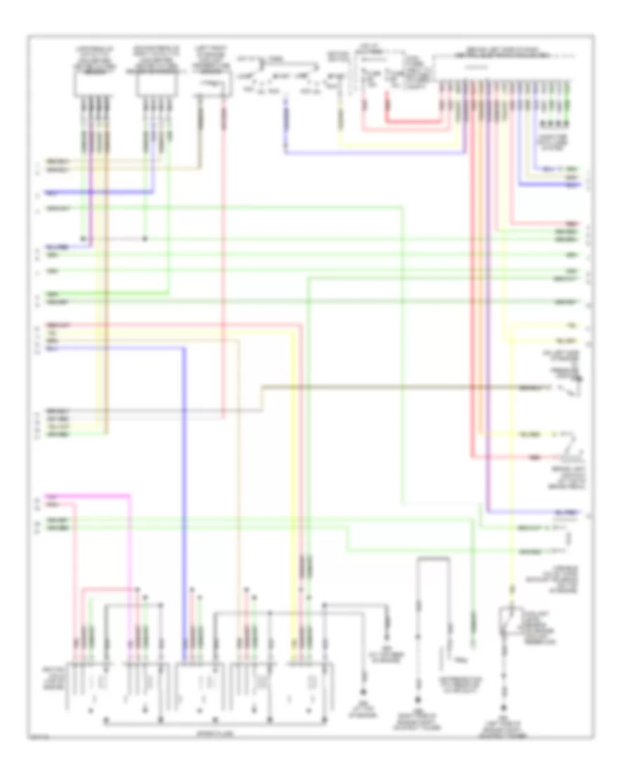
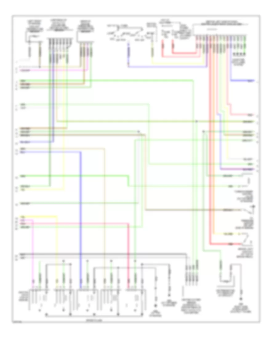
2.4L, Engine Performance Wiring Diagram, Early Production (2 of 3) for Volvo V70 2008
List of elements for 2.4L, Engine Performance Wiring Diagram, Early Production (2 of 3) for Volvo V70 2008:
- (behind left side of dash) central electronic module (cem)
- (downstream of right catalytic converter) heated oxygen sensor (diagnostic 1)
- (left front of engine) coolant temperature sensor
- (on left side of engine) oil pressure monitor
- (upstream of catalytic converter) heated oxygen sensor
- A16
- Acc
- Air preheating ptc resistor (in air duct)
- B11
- B16
- Brake light contact (at top of brake pedal)
- C14
- C21
- C22
- C34
- C35
- Computer data lines system
- Coolant level sensor (on engine coolant reservoir)
- D16
- D34
- D44
- D45
- D49
- D60
- Fuse e4 15a
- Fuse e5 10a
- G88 (at top of engine)
- G89 (at top rear of engine)
- G93 (left side of engine compt, on strut tower)
- G96 (right side of engine compt, on strut tower)
- Hot at all times
- Ignition coils (top of engine)
- Ignition switch
- Lock
- Main fuses (next to battery, in cargo compt)
- Nca
- Pnk
- Red
- Run
- Spark plugs
- Start
- Variable valve timing exhaust solenoid (on top of engine)
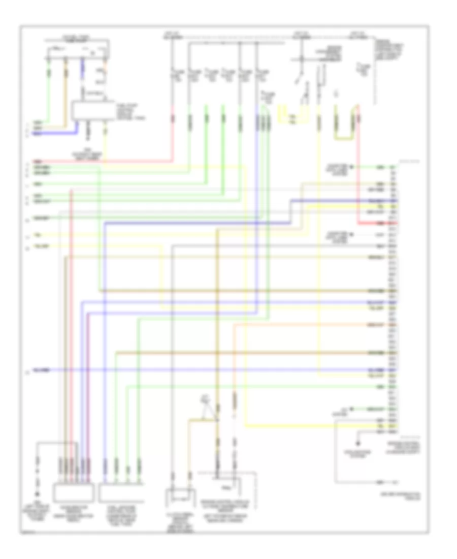
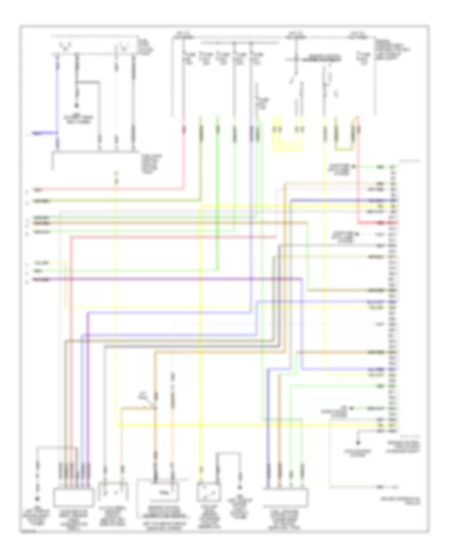
2.4L, Engine Performance Wiring Diagram, Early Production (3 of 3) for Volvo V70 2008
List of elements for 2.4L, Engine Performance Wiring Diagram, Early Production (3 of 3) for Volvo V70 2008:
- (in fuel tank) fuel pump
- A/c system
- Accelerator sensor (near accelerator pedal)
- B10
- B11
- B12
- B13
- B14
- B15
- B16
- B17
- B18
- B19
- B20
- B21
- B22
- B23
- B24
- B25
- B26
- B27
- B28
- B29
- B30
- B31
- B32
- B33
- B34
- B35
- B36
- B37
- B38
- B39
- B40
- B41
- B42
- B43
- B44
- B45
- B46
- B47
- B48
- Clutch pedal sensor (manual) (behind left side of dash)
- Computer data lines system
- Cooling fans system
- Driver information module
- Engine compartment distribution (left side of eng compt)
- Engine control module (ecm) (in engine compt)
- Engine control module outside temperature sensor
- Engine management system main relay
- Fuel leakage control pump (under rear of vehicle, near fuel tank)
- Fuel pump control module (on fuel tank)
- Fuse b10 20a
- Fuse b11 10a
- Fuse b12 15a
- Fuse b13 10a
- Fuse b14 20a
- Fuse b15 10a
- Fuse b23 10a
- Fuse b8 15a
- G48 (on right rear seat riser)
- G93 (left side of engine compt, on strut tower)
- Hot at all times
- Left power exterior rearview mirror)
- M/t only
- Nca
- Red
2.5L TURBO
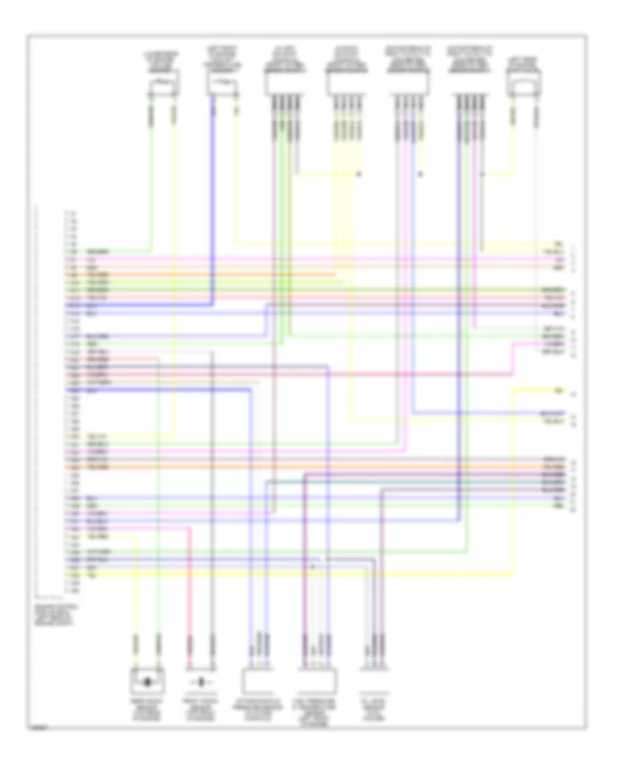
2.5L Turbo, Engine Performance Wiring Diagram, Early Production (1 of 3) for Volvo V70 2008
List of elements for 2.5L Turbo, Engine Performance Wiring Diagram, Early Production (1 of 3) for Volvo V70 2008:
- (at right front of engine compt) climate control system pressure sensor
- (in intake
- (left side of engine) intake manifold temperature sensor
- (lower left front of engine) oil level sensor
- (right side of engine compt, on strut tower)
- A10
- A11
- A12
- A13
- A14
- A15
- A16
- A17
- A18
- A19
- A20
- A21
- A22
- A23
- A24
- A25
- A26
- A27
- A28
- A29
- A30
- A31
- A32
- A33
- A34
- A35
- A36
- A37
- A38
- A39
- A40
- A41
- A42
- A43
- A44
- A45
- A46
- A47
- A48
- A49
- A50
- A51
- A52
- A53
- A54
- A55
- A56
- A57
- A58
- A59
- A60
- A61
- A62
- A63
- A64
- A65
- A66
- A67
- A68
- A69
- A70
- Air duct) mass airflow (maf) sensor
- Computer data lines system
- Cooling fans system
- Engine control module (in engine compt)
- Engine throttle body
- Evap valve (left side of engine compt)
- Exhaust side camshaft position sensor (on top left rear of engine)
- Front knock sensor (on left front side of eng)
- Fuel injectors (top of engine)
- G96
- Impulse sensor (at rear of eng)
- Intake side camshaft position sensor (on top rear of engine)
- Nca
- Pnk
- Rear knock sensor (on left rear side of eng)
- Red
- Variable valve timing intake solenoid (on top rear of engine)
- Variable valve timing outlet solenoid (on top of eng)
2.5L Turbo, Engine Performance Wiring Diagram, Early Production (2 of 3) for Volvo V70 2008
List of elements for 2.5L Turbo, Engine Performance Wiring Diagram, Early Production (2 of 3) for Volvo V70 2008:
- (behind left side of dash) central electronic module (cem)
- (left front of engine)
- (rear of engine) pressure & temperature sensor
- (upstream of catalytic converter) heated oxygen sensor
- A16
- Acc
- Air preheating ptc resistor (in air duct)
- B11
- B16
- Brake light contact (at top of brake pedal)
- C14
- C21
- C22
- C34
- C35
- Computer data lines system
- Coolant temperature sensor
- D16
- D34
- D49
- D60
- Fuse e4 15a
- Fuse e5 10a
- G88 (at top of engine)
- G89 (at top rear of engine)
- G96 (right side of eng compt, on strut tower)
- Heated oxygen sensor (diagnostic 1) (downstream of right catalytic converter)
- Hot at all times
- Ignition coils (top of engine)
- Ignition switch
- Lock
- Main fuses (next to battery, in cargo compt)
- Nca
- Off
- Oil pressure monitor (on left side of engine)
- Pnk
- Red
- Run
- Spark plugs
- Start
- Turbocharger control valve (on top rear of engine)
2.5L Turbo, Engine Performance Wiring Diagram, Early Production (3 of 3) for Volvo V70 2008
List of elements for 2.5L Turbo, Engine Performance Wiring Diagram, Early Production (3 of 3) for Volvo V70 2008:
- Accelerator pedal sensor (near accelerator pedal)
- Air conditioning system
- B10
- B11
- B12
- B13
- B14
- B15
- B16
- B17
- B18
- B19
- B20
- B21
- B22
- B23
- B24
- B25
- B26
- B27
- B28
- B29
- B30
- B31
- B32
- B33
- B34
- B35
- B36
- B37
- B38
- B39
- B40
- B41
- B42
- B43
- B44
- B45
- B46
- B47
- B48
- Clutch pedal sensor (manual) (behind left side of dash)
- Computer data lines system
- Coolant level sensor (on engine coolant reservoir)
- Cooling fans system
- Driver information module
- Engine compartment distribution box (left side of eng compt)
- Engine control module (ecm) (in engine compt)
- Engine control module outside temperature sensor
- Engine control system main relay
- Fuel leakage control pump (under rear of vehicle, near fuel tank)
- Fuel pump (in fuel tank)
- Fuel pump control module (on fuel tank)
- Fuse b10 20a
- Fuse b11 10a
- Fuse b12 15a
- Fuse b14 20a
- Fuse b15 15a
- Fuse b19 10a
- Fuse b8 15a
- G48 (on right rear seat riser)
- G93 (left side of engine compt, on strut tower)
- Hot at all times
- Left power exterior rearview mirror
- M/t only
- Nca
- Red
3.2L
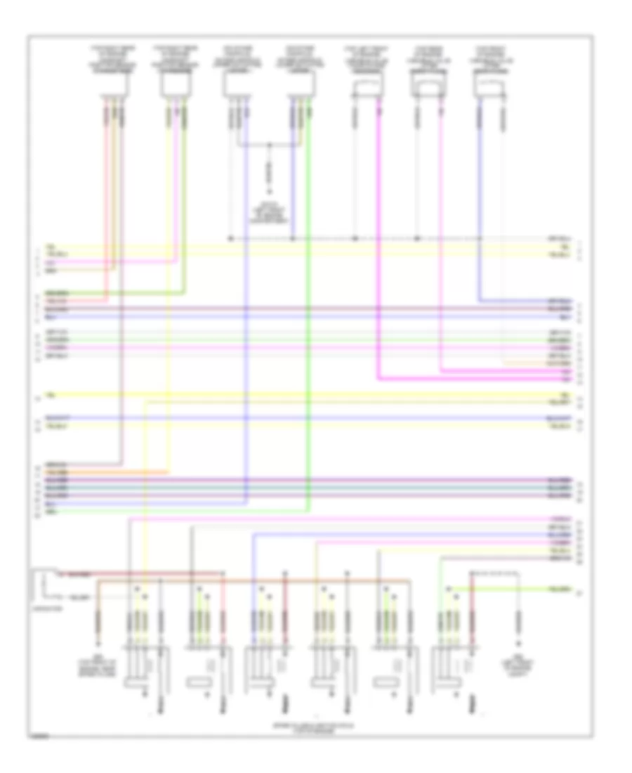
3.2L, Engine Performance Wiring Diagram, Late Production (1 of 5) for Volvo V70 2008
List of elements for 3.2L, Engine Performance Wiring Diagram, Late Production (1 of 5) for Volvo V70 2008:
- (downstream of right catalytic converter) rear oxygen sensor (bank 1)
- (downstream of right catalytic converter) rear oxygen sensor (bank 2)
- (in left exhaust manifold) front oxygen sensor (bank 1)
- (in right exhaust manifold) front oxygen sensor (bank 2)
- (left front of engine) coolant temperature sensor
- (left rear of engine) evap valve
- (lower rear of engine) impulse sensor
- A10
- A11
- A12
- A13
- A14
- A15
- A16
- A17
- A18
- A19
- A20
- A21
- A22
- A23
- A24
- A25
- A26
- A27
- A28
- A29
- A30
- A31
- A32
- A33
- A34
- A35
- A36
- A37
- A38
- A39
- A40
- A41
- A42
- A43
- A44
- A45
- A46
- A47
- A48
- A49
- A50
- Engine control module (ecm) (left rear of engine compt)
- Front knock sensor (top front of engine)
- Fuel pressure & temperature sensor (left front of engine)
- Intake manifold pressure sensor (in intake manifold)
- Nca
- Oil level sensor (in oil cooler)
- Rear knock sensor (top rear of engine)
3.2L, Engine Performance Wiring Diagram, Late Production (2 of 5) for Volvo V70 2008
List of elements for 3.2L, Engine Performance Wiring Diagram, Late Production (2 of 5) for Volvo V70 2008:
- (on intake manifold) intake manifold lower actuating motor
- (on intake manifold) intake manifold upper actuating motor
- (top front of engine) variable valve lifter (rear plane)
- (top left front of engine) variable valve timing intake solenoid
- (top rear of engine) variable valve lifter (front plane)
- (top right rear of engine) camshaft position sensor (exhaust side)
- (top right rear of engine) camshaft position sensor (intake side)
- Capacitor
- G88 (top front of engine, near spark plugs)
- G89 (left front of engine compt)
- Gxx10 (left front of engine compartment)
- Nca
- Spark plugs & ignition coils (top of engine)
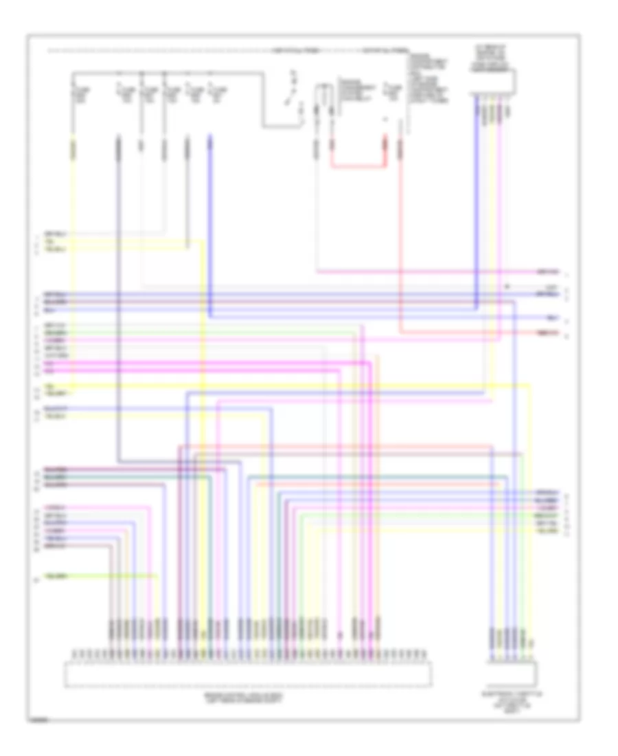
3.2L, Engine Performance Wiring Diagram, Late Production (3 of 5) for Volvo V70 2008
List of elements for 3.2L, Engine Performance Wiring Diagram, Late Production (3 of 5) for Volvo V70 2008:
- (at rear of engine, on air intake) mass airflow (maf) sensor
- A51
- A52
- A53
- A54
- A55
- A56
- A57
- A58
- A59
- A60
- A61
- A62
- A63
- A64
- A65
- A66
- A67
- A68
- A69
- A70
- A71
- A72
- A73
- A74
- A75
- A76
- A77
- A78
- A79
- A80
- A81
- A82
- A83
- A84
- A85
- A86
- A87
- A88
- A89
- A90
- A91
- A92
- A93
- A94
- A95
- A96
- A97
- Electronic throttle actuator (on throttle body)
- Engine compartment distribution box (left side of engine compartment, forward of strut tower)
- Engine control module (ecm) (left rear of engine compt)
- Engine management system main relay
- Fuse b30 10a
- Fuse b35 20a
- Fuse b36 10a
- Fuse b37 15a
- Fuse b38 10a
- Fuse b39 15a
- Fuse b41 5a
- Hot at all times
- Red
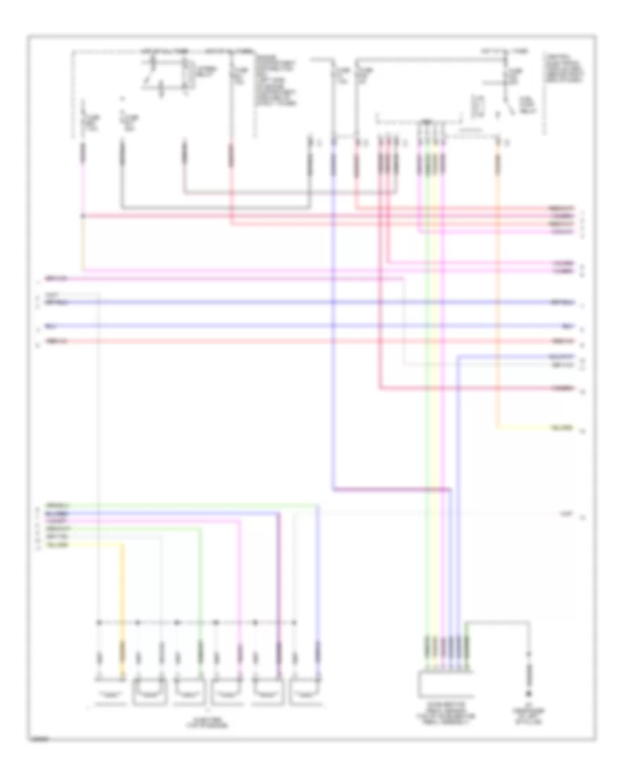
3.2L, Engine Performance Wiring Diagram, Late Production (4 of 5) for Volvo V70 2008
List of elements for 3.2L, Engine Performance Wiring Diagram, Late Production (4 of 5) for Volvo V70 2008:
- 15-feed relay
- Accelerator pedal sensor (top of accelerator pedal assembly)
- Cem
- Central electronic module (cem) (behind right end of dash)
- Engine compartment distribution box (left side of engine compartment, forward of strut tower)
- Fuel pump relay
- Fuse b17 20a
- Fuse b20 7.5a
- Fuse b31 15a
- Fuse f22 20a
- Fuse f28 5a
- Fuse f4 7.5a
- G7 (near base of left "b" pillar)
- Hot at all times
- Injectors (top of engine)
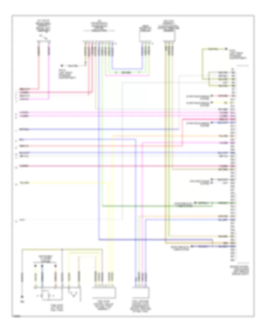
3.2L, Engine Performance Wiring Diagram, Late Production (5 of 5) for Volvo V70 2008
List of elements for 3.2L, Engine Performance Wiring Diagram, Late Production (5 of 5) for Volvo V70 2008:
- (at top of brake pedal assembly) brake light contact
- (on hvac assembly) climate control system pressure sensor
- (on transmission) transmission control module (tcm)
- Air conditioning system
- B10
- B11
- B12
- B13
- B14
- B15
- B16
- B17
- B18
- B19
- B20
- B21
- B22
- B23
- B24
- B25
- B26
- B27
- B28
- B29
- B30
- B31
- B32
- B33
- B34
- B35
- B36
- B37
- B38
- B39
- B40
- B41
- B42
- B43
- B44
- B45
- B46
- B47
- B48
- B49
- B50
- B51
- B52
- B53
- B54
- B55
- B56
- B57
- B58
- Computer data lines system
- Engine control module (ecm) (left rear of engine compt)
- Fuel leakage control pump (under rear of vehicle, forward of fuel tank)
- Fuel pump (at top of fuel tank)
- Fuel pump control module (on fuel tank assembly)
- G66
- Gear selector module
- Gxx10 (left front of engine compartment)
- Gxx5 (left front of engine compartment)
- Instrument cluster system
- Starting/charging system
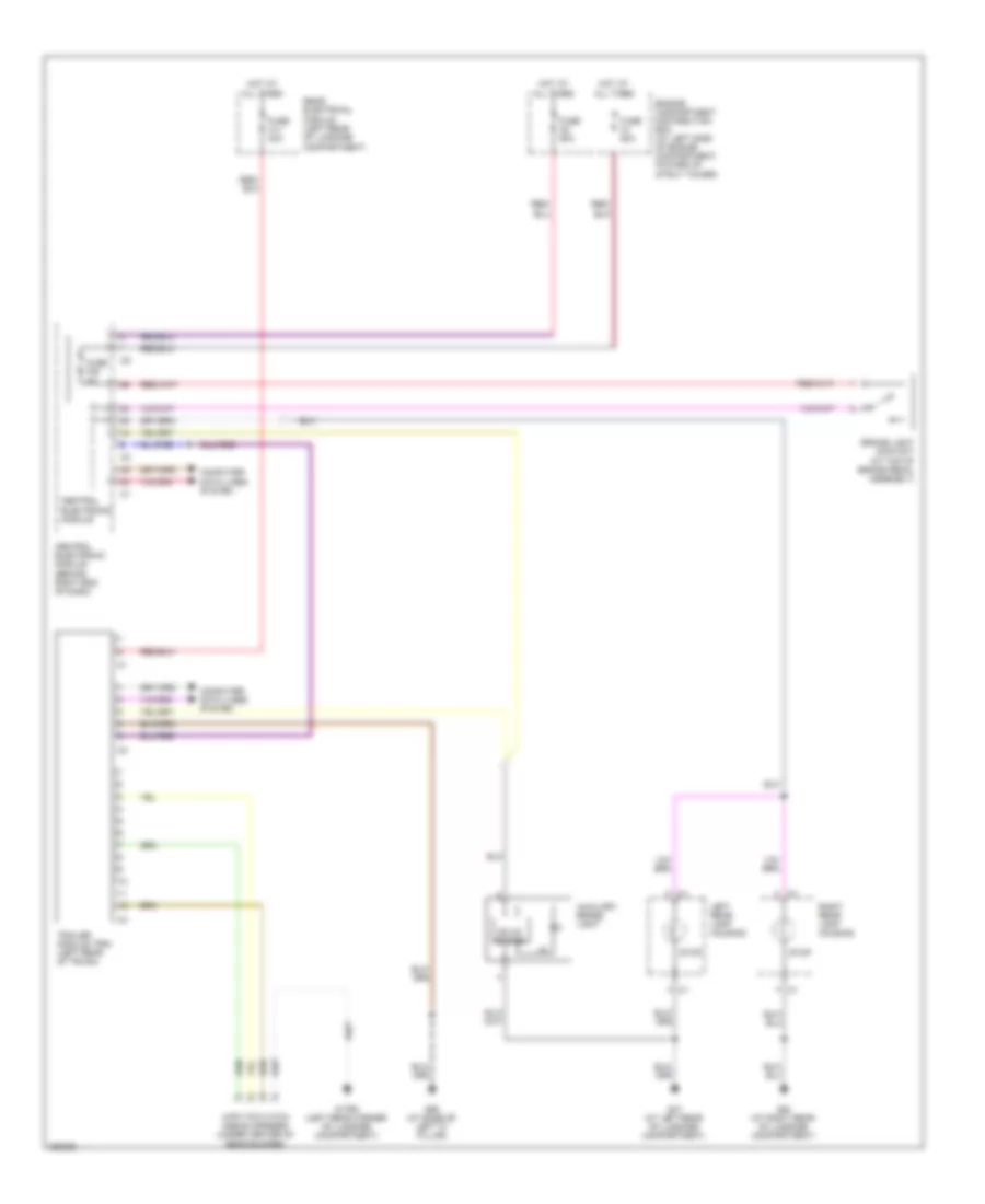
EXTERIOR LIGHTS
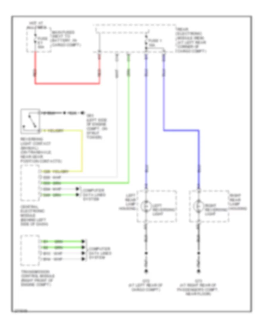
Back-up Lamps Wiring Diagram, Early Production for Volvo V70 2008
List of elements for Back-up Lamps Wiring Diagram, Early Production for Volvo V70 2008:
- B13
- B14
- B23
- C13
- C14
- C28
- Central electronic module (behind left side of dash)
- Computer data lines system
- D34
- D35
- D49
- D50
- Fuse 1 10a
- Fuse e1 60a
- G72 (at left rear of cargo compt)
- G73 (at right rear of passenger's compt, near floor)
- G93 (left side of engine compt, on strut tower)
- Hot at all times
- Left rear lamp housing
- Left reversing light
- Main fuses (next to battery, in cargo compt)
- Rear electronic module (rem) (at left rear corner of cargo compt)
- Red
- Reversing light contact (manual) (on transaxle, near gear position contacts)
- Right rear lamp housing
- Right reversing light
- Transmission control module (right front of engine compt)
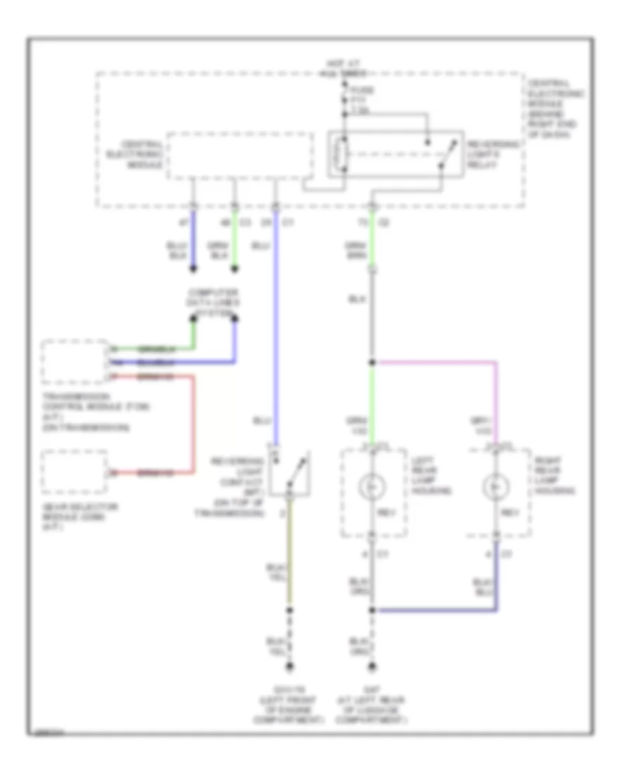
Back-up Lamps Wiring Diagram, Late Production for Volvo V70 2008
List of elements for Back-up Lamps Wiring Diagram, Late Production for Volvo V70 2008:
- Central electronic module
- Central electronic module (behind right end of dash)
- Computer data lines system
- Fuse f11 7.5a
- G47 (at left rear of luggage compartment)
- Gear selector module (gsm) (a/t)
- Gxx/10 (left front of engine compartment)
- Hot at all times
- Left rear lamp housing
- Rev
- Reversing light contact (m/t) (on top of transmission)
- Reversing lights relay
- Right rear lamp housing
- Transmission control module (tcm) (a/t) (on transmission)
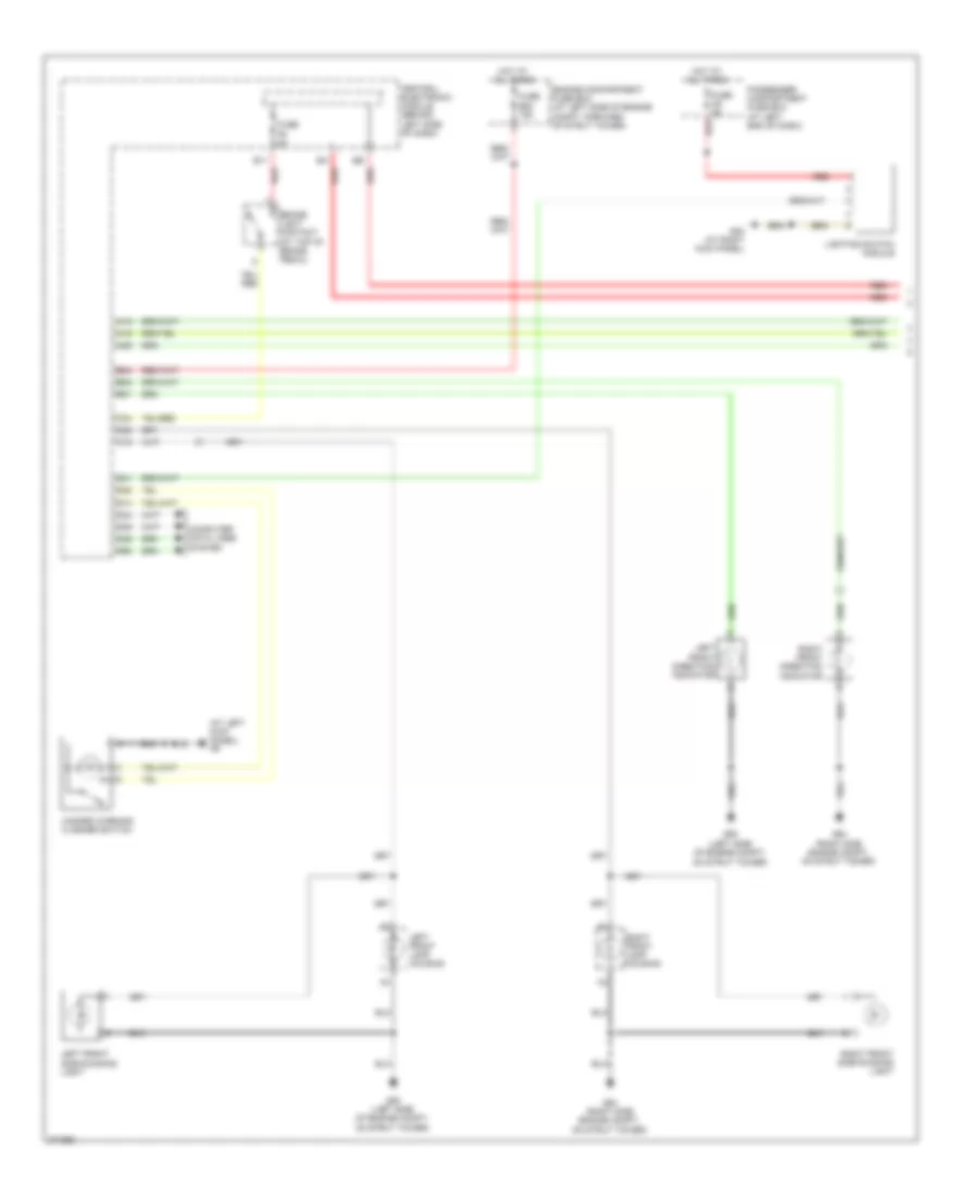
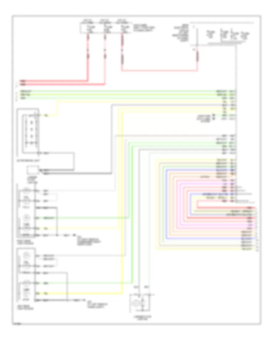
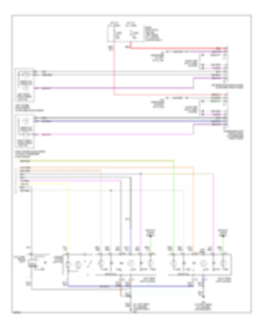
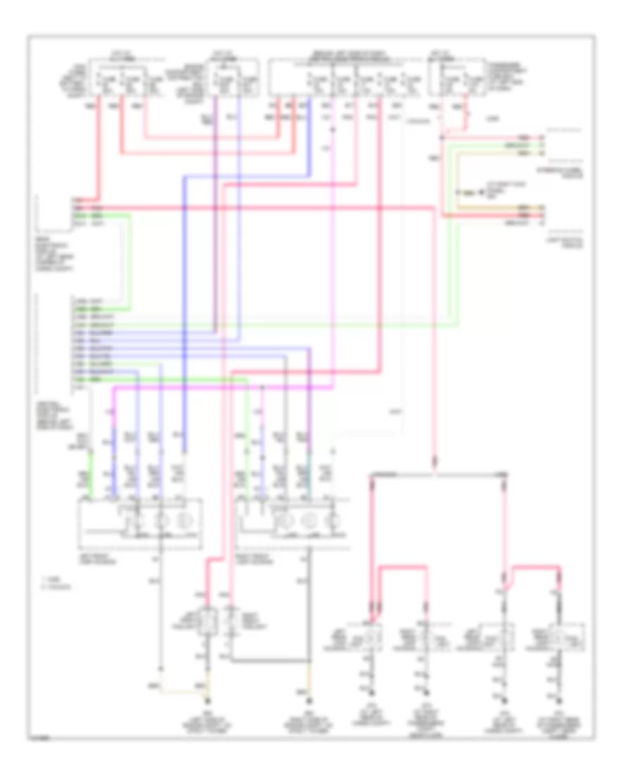
Exterior Lamps Wiring Diagram, Early Production (1 of 3) for Volvo V70 2008
List of elements for Exterior Lamps Wiring Diagram, Early Production (1 of 3) for Volvo V70 2008:
- (at left kick panel) g6
- (left side of engine compt, on strut tower)
- A12
- A15
- A29
- B11
- B24
- B31
- B32
- Brake light contact (at top of brake pedal)
- C19
- C20
- C34
- Central electronic module (behind left side of dash)
- Computer data lines system
- D14
- D22
- D34
- D35
- D41
- D49
- D50
- Engine compartment fuse box (at left side of engine compt, forward of strut tower)
- Fuse b20 15a
- Fuse c9 5a
- Fuse f9 5a
- G84 (at right kick panel)
- G93
- G93 (left side of engine compt, on strut tower)
- G94 (right side engine compt, on strut tower)
- Hazard warning flasher switch
- Hot at all times
- Left front direction indicator
- Left front lamp housing
- Left front side running light
- Lighting switch module
- Passenger compartment fuse box (at left end of dash)
- Red
- Right front direction indicator
- Right front lamp housing
- Right front side running light
Exterior Lamps Wiring Diagram, Early Production (2 of 3) for Volvo V70 2008
List of elements for Exterior Lamps Wiring Diagram, Early Production (2 of 3) for Volvo V70 2008:
- (4/7-pin)
- A18
- A20
- A21
- B10
- B11
- C13
- C14
- Computer data lines system
- Extra brake light
- F10
- Fuse e1 60a
- Fuse e4 50a
- Fuse e5 50a
- Fuse f20 20a
- Fuse f29 25a
- Fuse f30 25a
- Fuse f7 15a
- G72 (at left rear of cargo compt)
- G73 (at right rear of passenger's compt near floor)
- Hot at all times
- Left rear lamp housing
- License plate lighting
- Main fuses (next to battery, in cargo compt)
- Pnk
- Rear electronic module (at left rear corner of cargo compt)
- Red
- Right rear lamp housing
- Stop
- Tail
- Tail 2
- Turn
Exterior Lamps Wiring Diagram, Early Production (3 of 3) for Volvo V70 2008
List of elements for Exterior Lamps Wiring Diagram, Early Production (3 of 3) for Volvo V70 2008:
- (4/7-pin socket)
- (7-pin socket) (under rear bumper)
- (left rear of cargo compt) g120
- (left rear of cargo compt) trailer module (trm)
- 13-pin socket
- 4-pin socket
- 4/7-pin socket
- 7-pin & 4/7-pin socket
- 7-pin socket
- A10
- A11
- A11 pnk
- A12
- Back-up lights
- Fog light
- G120 (left rear of cargo compt)
- Gnd
- L turn
- Nca
- Pnk
- Position
- R turn
- Red
- Reverse indication
- Stop light
- Stop/l turn
- Stop/l turn sig
- Stop/r turn
- Stop/r turn sig
- Tow hitch cable converter harness (left rear corner of cargo compt)
- Tow hitch cable harness (13-pin socket) (under rear bumper)
- Tow hitch cable harness (4-pin socket) (under rear bumper)
- Tow hitch cable harness (7-pin socket) (under rear bumper)
- Trailer module (trm) (left rear of cargo compt)
Exterior Lamps Wiring Diagram, Late Production (1 of 2) for Volvo V70 2008
List of elements for Exterior Lamps Wiring Diagram, Late Production (1 of 2) for Volvo V70 2008:
- Auxiliary light (accessory) relay (right front of engine compartment)
- Auxiliary lights switch
- Brake light contact (at top of brake pedal assembly)
- Central electronic module
- Central electronic module (behind right end of dash)
- Climate control module (ccm)
- Computer data lines system
- Engine compartment distribution box (at left side of engine compartment, foward of strut tower)
- Fuse a1 50a
- Fuse a2 50a
- Fuse b23 5a
- Fuse b28 20a
- Fuse f28 5a
- G-al (right front of engine compt)
- G10 (under right side of front passenger's seat)
- G83 (under driver's door sill)
- G93 (at left front of engine compartment)
- G94 (at right front of engine compartment)
- Hazard warning flasher switch
- Hot at all times
- Keyless vehicle module (kvm) (right side of luggage compartment)
- Left front auxiliary light
- Left front lamp housing
- Light switch module (lsm)
- Park
- Red
- Right front auxiliary light
- Right front lamp housing
- Turn
Exterior Lamps Wiring Diagram, Late Production (2 of 2) for Volvo V70 2008
List of elements for Exterior Lamps Wiring Diagram, Late Production (2 of 2) for Volvo V70 2008:
- (4)
- (at left rear of luggage compartment) g47
- (not used)
- Auxiliary brake light
- Back-up lamps circuit
- Computer data lines system
- Direction indicator
- Driver's door module (ddm) (in driver's front door)
- Fog
- Fuse a1 25a
- Fuse a2 25a
- G15 (near base of right "b" pillar)
- G48 (at right rear of luggage compartment)
- G6 (near base of left "b" pillar)
- Hot at all times
- Left front door mirror lighting
- Left power door mirror (in driver's door mirror)
- Left rear lamp housing
- License plate lighting
- Passenger door module (pdm) (in passenger front door)
- Pos
- Rear electrical center (left rear of luggage compartment)
- Red
- Rev
- Right front door mirror lighting
- Right power door mirror (in front passenger door mirror)
- Right rear lamp housing
- Solid state
- Stop
- Stop/tail
- Turn
Trailer Tow Wiring Diagram, Late Production with 4-Pin for Volvo V70 2008
List of elements for Trailer Tow Wiring Diagram, Late Production with 4-Pin for Volvo V70 2008:
- (4)
- 4-pin tow hitch cable harness (under center of rear bumper)
- Auxiliary brake light
- Brake light contact (at top of brake pedal assembly)
- Central electronic module
- Central electronic module (behind right end of dash)
- Computer data lines system
- Engine compartment distribution box (at left side of engine compartment, foward of strut tower)
- Fuse a1 50a
- Fuse a11 40a
- Fuse a2 50a
- Fuse f28 5a
- G-trm (left rear corner of luggage compartment)
- G47 (at left rear of luggage compartment)
- G48 (at right rear of luggage compartment)
- G65 (at base of left "c" pillar)
- Hot at all times
- Left rear lamp housing
- Rear electrical module (left rear of luggage compartment)
- Right rear lamp housing
- Solid state
- Stop
- Trailer module (trm) (left rear of trunk)
Trailer Tow Wiring Diagram, Late Production with 7-Pin for Volvo V70 2008
List of elements for Trailer Tow Wiring Diagram, Late Production with 7-Pin for Volvo V70 2008:
- (4)
- 7-pin tow hitch cable harness (under center of rear bumper)
- Auxiliary brake light
- Brake light contact (at top of brake pedal assembly)
- Central electronic module
- Central electronic module (behind right end of dash)
- Computer data lines system
- Engine compartment distribution box (at left side of engine compartment, foward of strut tower)
- Fuse a1 50a
- Fuse a11 40a
- Fuse a2 50a
- Fuse f28 5a
- G-trm (left rear corner of luggage compartment)
- G47 (at left rear of luggage compartment)
- G48 (at right rear of luggage compartment)
- G65 (at base of left "c" pillar)
- Hot at all times
- Left rear lamp housing
- Rear electrical module (left rear of luggage compartment)
- Red
- Right rear lamp housing
- Solid state
- Stop
- Trailer module (trm) (left rear of trunk)
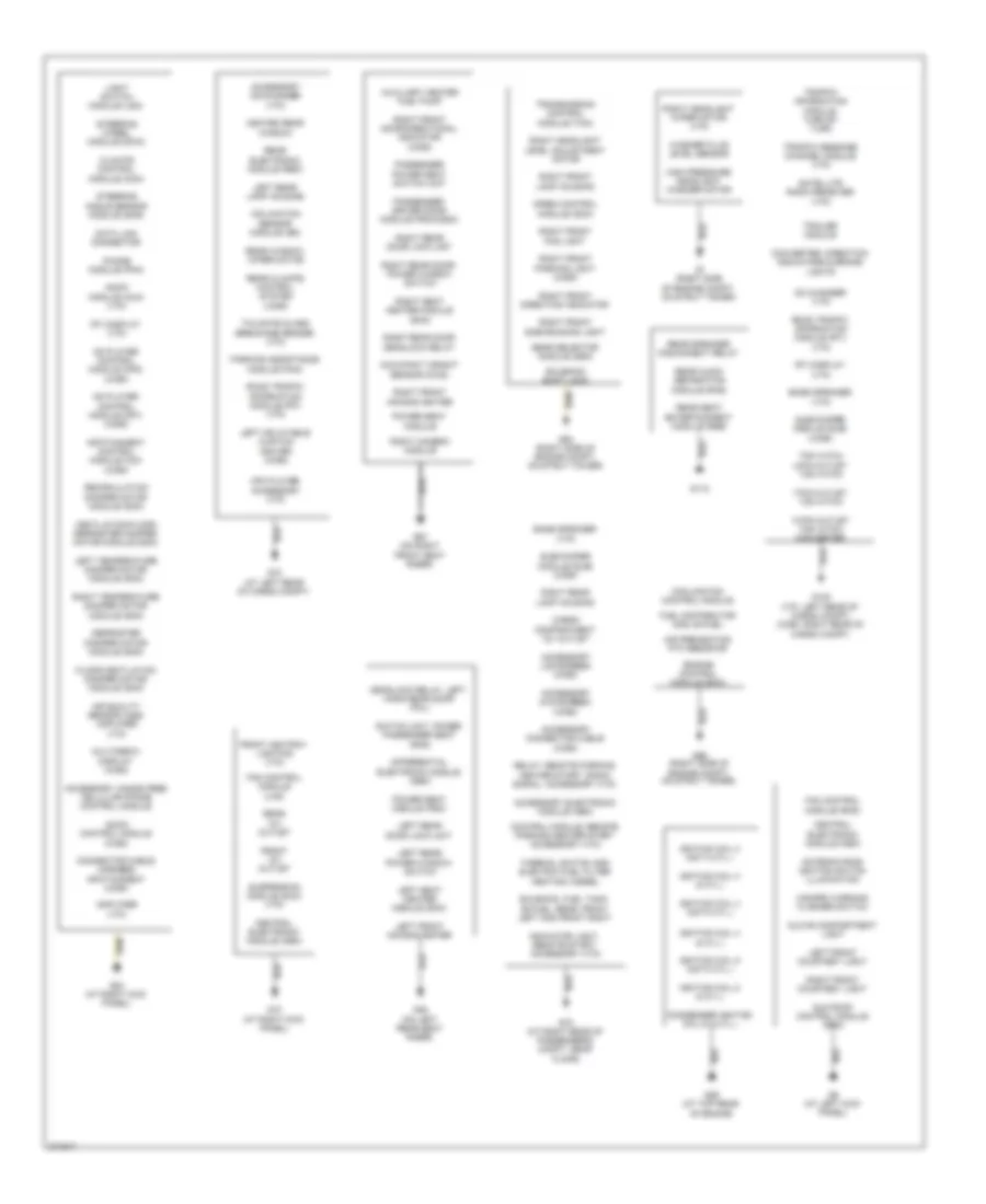
GROUND DISTRIBUTION
Ground Distribution Wiring Diagram, Early Production (1 of 2) for Volvo V70 2008
List of elements for Ground Distribution Wiring Diagram, Early Production (1 of 2) for Volvo V70 2008:
- 13-pin outlet tow hitch converter
- 7-pin outlet tow hitch
- Accessory cd-changer (v70)
- Accessory connector cable (xc90)
- Accessory dvd-screen (xc90)
- Accessory electronic module (aem)
- Accessory hands free cellular phone control module
- Accessory lcd-screen (xc90)
- Air preheating ptc resistor
- Air quality sensor (aqs) amplifier (v70)
- Amplifier (v70)
- Antenna ring/ ignition switch illumination
- Audio control module (xc90)
- Audio module (aum) (v70)
- Auxiliary heater fuel pump
- Bass speaker (v70)
- Cargo compartment 12v outlet
- Cd changer (v70)
- Cd player control module (mp2) (xc90)
- Central electronic module (cem)
- Climate control module (ccm)
- Condenser ignition coil 6 (8 cyl.)
- Connector cable harness infotainment (xc90)
- Control module, remote parking heater start accessory (v70)
- Converter, direction indicators & brake lights
- Cooling fan control module
- Data link connector
- Deadlock relay, left hand rear door (pcl)
- Defroster damper motor module (dmm)
- Differential electronic module (dem)
- Engine control module (ecm)
- Fan control module (lhd)
- Fan control module (rhd)
- Floor/ventilation damper motor module (dmm)
- Front 12v outlet
- Front ashtray lighting (v70)
- Fuel distributor gas, bi-fuel
- G1 (right side of engine compt, on strut tower)
- G10 (at right kick panel)
- G118
- G120 (v70: left rear of cargo compt) (xc90: right rear of cargo compt)
- G46 (on left rear seat riser)
- G6 (at left kick panel)
- G67 (on right front seat riser)
- G72 (at left rear of cargo compt)
- G73 (at right rear of passenger's compt, near floor)
- G84 (at right kick panel)
- G89 (at top rear of engine
- G94 (right side of engine compt, on strut tower)
- G96 (right side of engine compt, on strut tower)
- Gear selector module (gsm)
- Glove compartment light
- Hazard warning flasher switch
- Heated rear window
- High pressure headlight washer motor
- Ignition coil 3 (8 cyl.)
- Ignition coil 3 (not 8 cyl.)
- Ignition coil 4 (8 cyl.)
- Ignition coil 4 (not 8 cyl.)
- Ignition coil 5 (8 cyl.)
- Ignition coil 5 (not 8 cyl.)
- Inclination sensor module (ism)
- Indicator light, remote start, accessory (v70)
- Infotainment control module (icm) (xc90)
- Left front air bag igniter
- Left front courtesy light
- Left inflatable curtain igniter (xc90)
- Left rear door lock unit
- Left rear lamp housing
- Left rear power window switch
- Left seat heater module (shm)
- Left temperature damper motor module (dmm)
- Light switch module (lsm)
- Md player control module (mp1) (xc90)
- Mp3 player accessory (v70)
- Multimedia display (xc90)
- Occupant weight sensor (ows)
- Parking assistance module (pam)
- Passenger power seat switch unit
- Passenger/ driver door module (pdm)/(ddm)
- Phone module (phm)
- Power seat module
- Power seat module (psm)
- Rear 12v outlet
- Rear audio separation module (ras)
- Rear climate control system (xc90)
- Rear electronic module (rem)
- Rear seat entertainment module (rse)
- Rear speaker disconnect relay
- Rear window wiper motor
- Recirculation damper motor module (dmm)
- Relay, remote parking heater start, radio signal, accessory (v70)
- Right camera module
- Right front air bag igniter
- Right front courtesy light
- Right front direction indicator
- Right front door directional indicator (xc90)
- Right front fog light
- Right front lamp housing
- Right front parking light (xc90)
- Right front side running light
- Right headlight level adjustment motor
- Right headlight wiper motor (v70)
- Right rear door deadlock relay
- Right rear door lock unit
- Right rear door/ power window switch
- Right rear lamp housing
- Right seat heater module (shm)
- Right temperature damper motor module (dmm)
- Road traffic information module (rti) (v70)
- Rti display (v70)
- Satellite radio receiver (v70)
- Siren control module (scm)
- Solenoid shift lock
- Solenoid, fuel tank, bi-fuel, rear, front left and front right
- Steering angle sensor module (sas)
- Steering wheel module (swm)
- Subwoofer module (sub) (xc90)
- Sun roof control module (srm)
- Suspension module (sum) (v70)
- Switch unit, power passenger seat (rhd)
- Tailgate glass breakage sensor (v70)
- Thermal switch and electric fuel filter heating, diesel
- Tow hitch 4-pin outlet tow hitch
- Traffic information module turn by turn
- Traffic message channel module (v70)
- Trailer module
- Transmission control module (tcm)
- Ventilation/floor/ defroster damper motor module (dmm)
- Washer fluid level sensor
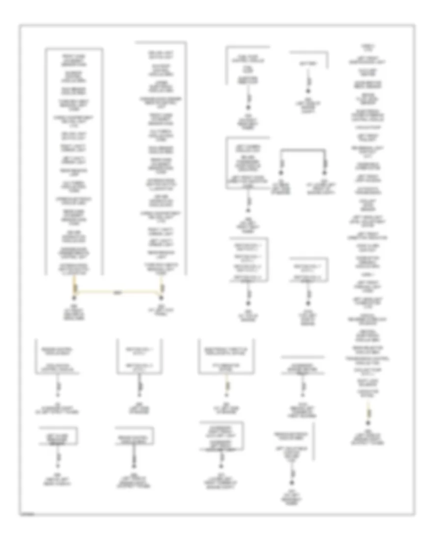
Ground Distribution Wiring Diagram, Early Production (2 of 2) for Volvo V70 2008
List of elements for Ground Distribution Wiring Diagram, Early Production (2 of 2) for Volvo V70 2008:
- (above left rear window)
- (at lower left front of engine compt)
- Accelerator pedal sensor
- Accessory engine heater relay
- Accessory left front auxiliary light
- Accessory right front auxiliary light
- Antenna ring/ ignition switch illumination
- Automatic transmission
- Auxiliary heater
- Battery
- Brake control module (bcm)
- Brake fluid level sensor
- Capacitor bi-fuel
- Cargo compartment ceiling light (v70)
- Ceiling light switch unit
- Central electronic module (cem)
- Combustion preheat module (cpm)
- Coolant level sensor
- Coolant pump (8 cyl.)
- Cooling fan control module
- Driver information module (dim)
- Driver/ passenger door module (ddm)/(pdm)
- Ejectors feed pump
- Electronic power steering control module
- Electronic throttle module (etm), bi-fuel
- Engine control module (ecm)
- Front mass movement sensor (mms)
- Fuel pump
- Fuel pump control module
- G100 (top left side of engine)
- G102 (behind left corner of front bumper)
- G2 (in engine compt on left strut tower)
- G4 (at rear left side of engine)
- G44
- G47 (on left rear seat riser)
- G48 (on right rear seat riser)
- G53 (left side of engine compt)
- G66 (on left front seat riser)
- G70 (lower left front corner of engine compt)
- G83 (at left kick panel)
- G88 (at top of engine)
- G90 (left side of engine)
- G91 (at left side of engine)
- G93 (left side of engine compt, on strut tower)
- G95 (left side of engine compt, on strut tower)
- G98 (at front center of headliner)
- G99
- Garage door opener remote control unit
- Gear selector module (gsm)
- Hood alarm contact
- Horn 1
- Horn 2 (v70)
- Ignition coil 1 (8 cyl.)
- Ignition coil 1 (not 8-cyl.)
- Ignition coil 2 (8 cyl.)
- Ignition coil 2 (not 8 cyl.)
- Ignition coil 7 (8 cyl.)
- Ignition coil 8 (8 cyl.)
- Left camera module (lcm)
- Left front direction indicator
- Left front door direction indicator (xc90)
- Left front foglight
- Left front lamp housing
- Left front parking light (xc90)
- Left front side running light
- Left glass breakage sensor
- Left headlight level adjustment motor
- Left headlight wiper motor (v70)
- Left inflatable curtain igniter (v70)
- Left vanity mirror light
- Left vanity mirror light
- Manual reverse interlock solenoid
- Multimedia module (mmm) (xc90)
- Ptc resistor bi-fuel
- Rain sensor module (rsm)
- Rear electronic module (rem)
- Rear mass movement sensor (mms) (xc90)
- Rear reading lamp
- Rear reading light
- Reversing light contact (m/t)
- Right vanity mirror light
- Right vanity mirror light
- Shift lock solenoid
- Sun roof control module (srm)
- Sunroof control module (srm)
- Third row seat reading light (xc90)
- Third row seats reading light (xc90)
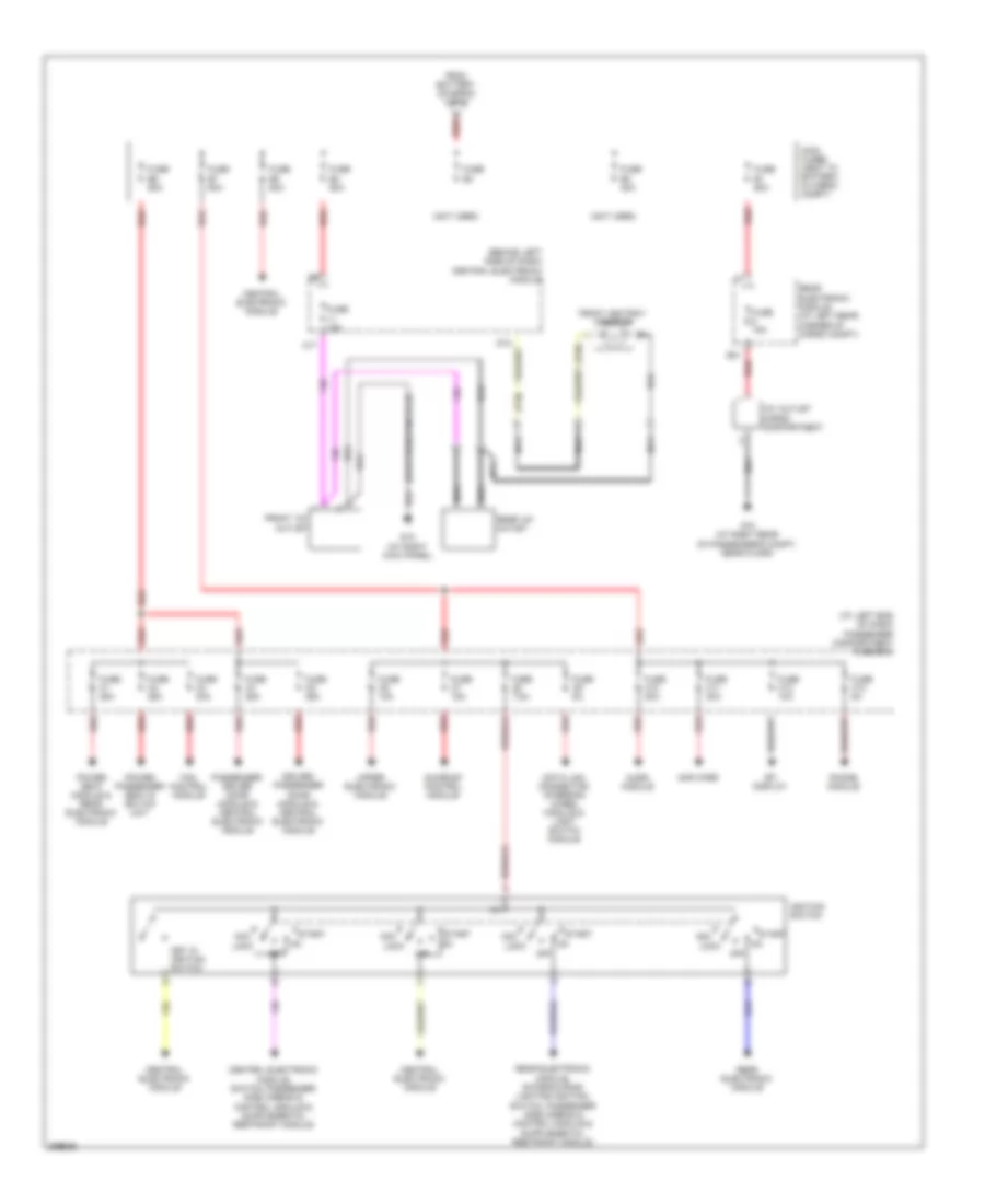
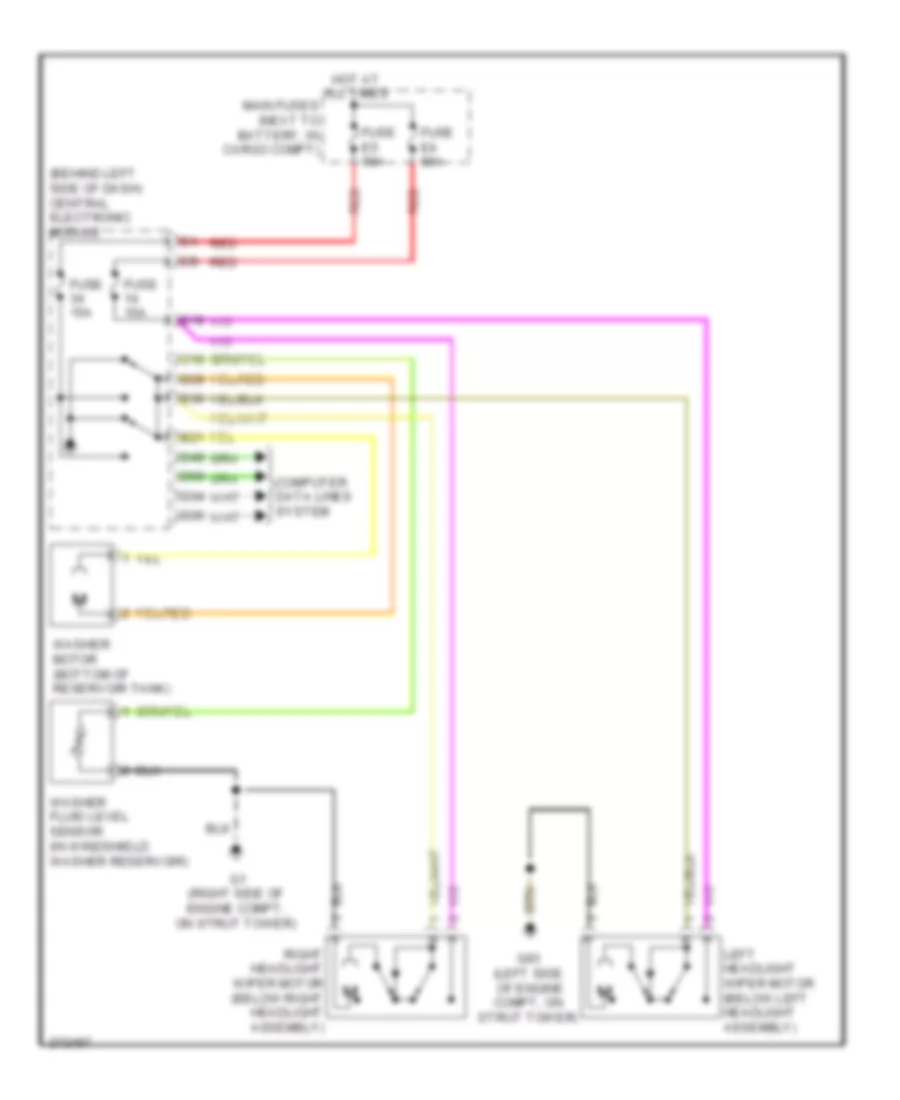
- Transmission control module (tcm)
- Upper electronic module (uem)
- Vacuum pump
- Windshield wiper motor
Ground Distribution Wiring Diagram, Late Production for Volvo V70 2008
List of elements for Ground Distribution Wiring Diagram, Late Production for Volvo V70 2008:
- 4-pin tow hitch cable harness outlet, 7-pin tow hitch cable harness outlet & 13-pin tow hitch cable harness outlet
- Battery
- Brake control module
- Central electronic module
- Central electronic module, hood alarm contact, coolant level sensor & forward-aimed radar
- Clutch pedal immobilizer contact, brake light diagnostic contact & accelerator pedal sensor
- Cooling fan control module, cooling fan control module 2 (v70) &
- Differential electronic module, left front side air bag igniter, left rear seat heater control module, trailer module & parking assistance camera module
- Driver's door power window switch,
- Electronic power steering control module, headlamp control module, brake fluid level sensor & siren control module
- Engine compartment
- Engine control module
- Fuel pump & fuel pump control module
- G-al (right front of engine compartment)
- G-infot (left rear corner of luggage compartment)
- G-trm (left rear corner of luggage compt)
- G1 (at right front of engine compartment, on fender)
- G10 (under right side of front passenger's seat)
- G15 (near base of right "b" pillar)
- G2 (at left front of engine compartment, on fender)
- G3 (left rear of engine compartment)
- G4 (at left front of engine compartment)
- G47 (at left rear of luggage compartment)
- G48 (at right rear of luggage compartment)
- G6 (near base of left "b" pillar)
- G65 (at base of left "c" pillar)
- G66
- G67 (at base of right "c" pillar)
- G68 (at base of right "c" pillar)
- G7 (near base of left "b" pillar)
- G83 (under driver's door sill)
- G84 (near base of right "b" pillar)
- G88 (at top front of engine, near spark plugs)
- G89 (left front of engine compt)
- G90 (at left side of engine)
- G93 (at left front of engine compt)
- G94 (at right front of engine compt)
- G95 (at left front of engine compt)
- G96 (at right front of engine compt)
- Ground connection
- Gxx10 (left front of engine compartment)
- Gxx14 (left front of engine compt)
- Gxx15 (right front of engine compartment)
- Gxx4 (lower left rear of engine)
- Gxx5 (left front of engine compt)
- Hazard warning flasher switch, climate control system, trunk lid private lock switch, fan control module, sunroof module, steering column lock module, remote keyless entry, remote receiver module, rain sensor module, ultrasonic sensor, air quality sensor, automatic anti-dazzle rearview mirror, ceiling light, remote control unit, glove compartment lighting, right vanity mirror lighting, left vanity mirror lighting, rear reading light, data link connector & dome light switch unit
- Heated fuel filter & auxiliary heater fuel pump
- Heated rear seat switch, driver's door module, left rear door module, gear selector module,
- Left front door lock contact, left rear door lock contact, left front central locking motor, left rear central locking motor, manual reverse interlock solenoid, front 12v outlet, power seat module, rear 12v outlet, navigation system portable, driver's seat heating module, front ashtray lighting, rear headphone sockets & dvd player/control module
- Left front lamp housing, left front fog light, washer fluid level sensor, driver information module (xc70),
- Left heated windshield washer nozzle, right heated windshield washer nozzle & high pressure headlight washer motor (v70)
- Parking assistance module, fuel filler cover lock motor, refrigeration box relay, right rear lamp housing, refrigeration box, 12v outlet, cargo compartment & heartbeat sensor
- Parking brake module, trunk handle switch, license plate lighting, left rear lamp housing, rear window wiper motor, rear window wiper relay, right rear lamp housing, auxiliary brake light, power operated tailgate module, tailgate lock unit, left tailgate pinch sensor, right tailgate pinch sensor, tailgate closing motor & heated rear window
- Passenger's door module, right rear door module, right front door lock contact, right rear door lock contact, right front central locking motor, right rear central locking motor, passenger's seat heating module, driver's door module & power passenger seat switch unit
- Ptc element
- Remote digital audio receiver, high level display front module, subwoofer module, audio module & multimedia module
- Reversing light contact, transmission control module, intake manifold upper actuating motor, intake manifold lower actuating motor & 1st gear switch indicator
- Right front auxiliary light & left front auxiliary light
- Right front lamp housing, right front fog light, horn 1, horn 2 & high pressure headlight washer motor (xc70)
- Spark plug & ignition coils
- Spark plug & ignition coils & capacitor
- Spark plug & ignition coils & capacitor (xc70)
- Suspension module, keyless vehicle module, passenger seat weight sensor(seat belt reminder), right rear seat heating control module & left front side air bag igniter
- Twin cooling fan control module (xc70)
- Wiper motor module & combustion preheater module
HEADLIGHTS
Headlamp Beam Adjustment Wiring Diagram, Early Production for Volvo V70 2008
List of elements for Headlamp Beam Adjustment Wiring Diagram, Early Production for Volvo V70 2008:
- (behind right headlight assembly)
- (left side of engine compt, on strut tower) g93
- (right side of engine compt, on strut tower) g94
- Central electronic module (behind left side of dash)
- Computer data lines system
- Fuse c9 5a
- Fuse e4 50a
- Fuse f16 10a
- G84 (at right kick panel)
- Headlight adjustment control (w/o bi x)
- Hot at all times
- Left headlight adjustment motor (behind left headlight assembly)
- Left rear angle sensor (w/ four-c/ bi-x) (in left rear wheelwell)
- Light switch module
- Passenger compartment fuse box (at left end of dash)
- Rear electronic module (at left rear corner of cargo compt)
- Red
- Right headlight adjustment motor
- Suspension module (under center console)
- W/ electronic suspension
- W/o electronic suspension
Headlamp Beam Adjustment Wiring Diagram, Late Production with Active Headlights for Volvo V70 2008
List of elements for Headlamp Beam Adjustment Wiring Diagram, Late Production with Active Headlights for Volvo V70 2008:
- 15-feed relay
- Central electronic module
- Central electronic module (behind right end of dash)
- Computer data lines system
- Contact reel (top of steering column)
- Engine compartment distribution box (at left side of engine compartment, foward of strut tower)
- Fuse a1 50a
- Fuse a2 50a
- Fuse b16 10a
- Fuse b27 5a
- G95 (at left front of engine compartment)
- Headlamp control module (hcm) (right rear of engine compartment)
- Hot at all times
- Left front lamp housing
- Nca
- Red
- Right front lamp housing
- Right front suspension height sensor (w/ four-c) (in right front wheelwell)
- Right front suspension height sensor (w/o four-c) (in right front wheelwell)
- Right rear suspension height sensor (w/ four-c) (in right rear wheelwell)
- Right rear suspension height sensor (w/o four-c) (in right rear wheelwell)
- Solar sensor, twilight sensor & indicator alarm (top center of dash)
- Steering angle sensor
- Steering wheel angle sensor module
- Steering wheel module (swm) (in steering column)
- Suspension module (sum) (behind center of rear seats)
Headlamp Beam Adjustment Wiring Diagram, Late Production with Automatic Beam Length Adjustment for Volvo V70 2008
List of elements for Headlamp Beam Adjustment Wiring Diagram, Late Production with Automatic Beam Length Adjustment for Volvo V70 2008:
- 15-feed relay
- Central electronic module
- Central electronic module (behind right end of dash)
- Computer data lines system
- Engine compartment distribution box (at left side of engine compartment, foward of strut tower)
- Fuse a1 50a
- Fuse a2 50a
- Fuse b16 10a
- Fuse b27 5a
- G95 (at left front of engine compartment)
- Headlamp control module (hcm) (right rear of engine compartment)
- Hot at all times
- Left front lamp housing
- Nca
- Red
- Right front lamp housing
- Right front suspension height sensor (w/ four-c) (in right front wheelwell)
- Right front suspension height sensor (w/o four-c) (in right front wheelwell)
- Right rear suspension height sensor (w/ four-c) (in right rear wheelwell)
- Right rear suspension height sensor (w/o four-c) (in right rear wheelwell)
- Suspension module (sum) (behind center of rear seats)
Headlamps & Fog Lamps Wiring Diagram, Early Production with Xenon Lamps for Volvo V70 2008
List of elements for Headlamps & Fog Lamps Wiring Diagram, Early Production with Xenon Lamps for Volvo V70 2008:
- (at right kick panel) g84
- (behind left side of dash) central electronic module
- A6 nca
- B17
- B18
- B23
- B27
- B28
- C13
- C14
- Central electronic module (behind left side of dash)
- D35
- D41
- D50
- D58
- Dip
- Drl
- Engine compartment distribution box (left side of engine compt)
- Fog light
- Fuse 10a
- Fuse 7.5a
- Fuse b16 20a
- Fuse b17 20a
- Fuse c10 5a
- Fuse c9 5a
- Fuse e1 60a
- Fuse e4 50a
- Fuse e5 50a
- G72 (at left rear of cargo compt)
- G73 (at right rear of passenger's compt, near floor)
- G93 (left side of engine compt, on strut tower)
- G94 (right side of engine compt, on strut tower)
- Hot at all times
- Left front foglight
- Left front lamp housing
- Left rear lamp housing
- Light switch module
- Main
- Main fuses (next to battery, in cargo compt)
- Nca
- Passenger compartment fuse box (at left end of dash)
- Pnk
- Rear electronic module (at left rear corner of cargo compt)
- Red
- Right front foglight
- Right front lamp housing
- Right rear lamp housing
- Steering wheel module
- V70/xc70
- Xc90
Headlamps & Fog Lamps Wiring Diagram, Early Production without Xenon Lamps for Volvo V70 2008
List of elements for Headlamps & Fog Lamps Wiring Diagram, Early Production without Xenon Lamps for Volvo V70 2008:
- (at right kick panel) g84
- (behind left side of dash) central electronic module
- A6 nca
- B17
- B18
- B23
- B27
- B28
- C13
- C14
- Central electronic module (behind left side of dash)
- D35
- D41
- D50
- D58
- Dip
- Drl
- Engine compartment distribution box (left side of engine compt)
- Fog light
- Fuse 10a
- Fuse 7.5a
- Fuse b16 20a
- Fuse b17 20a
- Fuse c10 5a
- Fuse c9 5a
- Fuse e1 60a
- Fuse e4 50a
- Fuse e5 50a
- G72 (at left rear of cargo compt)
- G73 (at right rear of passenger's compt, near floor)
- G93 (left side of engine compt, on strut tower)
- G94 (right side of engine compt, on strut tower)
- Hot at all times
- Left front foglight
- Left front lamp housing
- Left rear lamp housing
- Light switch module
- Main
- Main fuses (next to battery, in cargo compt)
- Nca
- Passenger compartment fuse box (at left end of dash)
- Pnk
- Rear electronic module (at left rear corner of cargo compt)
- Red
- Right front foglight
- Right front lamp housing
- Right rear lamp housing
- Steering wheel module
- V70/xc70
- Xc90
Headlamps Wiring Diagram, Late Production with Bi-Xenon Lamps for Volvo V70 2008
List of elements for Headlamps Wiring Diagram, Late Production with Bi-Xenon Lamps for Volvo V70 2008:
- (except s80)
- (s80)
- Central electronic module
- Central electronic module (behind right end of dash)
- Computer data lines system
- Driver information module (dim)
- Engine compartment distribution box (at left side of engine compartment, foward of strut tower)
- Fog light
- Front fog light relay
- Fuse a1 50a
- Fuse b23 5a
- Fuse f13 15a
- Fuse f9 15a
- G47 (at left rear of luggage compartment)
- G48 (in right rear of luggage compartment)
- G83 (under driver's door sill)
- G93 (at left front of engine compartment)
- G94 (at right front of engine compartment)
- High
- High beam relay
- Hot at all times
- Left front fog light
- Left front lamp housing
- Left rear lamp housing
- Light switch module (lsm)
- Pos
- Right front fog light
- Right front lamp housing
- Right rear lamp housing (s80)
- Steering wheel module (swm) (in steering column)
- Turn
- Xenon low
Headlamps Wiring Diagram, Late Production without Bi-Xenon Lamps for Volvo V70 2008
List of elements for Headlamps Wiring Diagram, Late Production without Bi-Xenon Lamps for Volvo V70 2008:
- (except s80)
- (s80)
- Central electronic module
- Central electronic module (behind right end of dash)
- Computer data lines system
- Driver information module (dim)
- Engine compartment distribution box (at left side of engine compartment, foward of strut tower)
- Fog light
- Front fog light relay
- Fuse a1 50a
- Fuse b23 5a
- Fuse f13 15a
- Fuse f9 15a
- G47 (at left rear of luggage compartment)
- G48 (in right rear of luggage compartment)
- G83 (under driver's door sill)
- G93 (at left front of engine compartment)
- G94 (at right front of engine compartment)
- High
- High beam relay
- Hot at all times
- Left front fog light
- Left front lamp housing
- Left rear lamp housing
- Light switch module (lsm)
- Low
- Pos
- Right front fog light
- Right front lamp housing
- Right rear lamp housing (s80)
- Steering wheel module (swm) (in steering column)
- Turn
Headlamps Leveling Wiring Diagram, Early Production for Volvo V70 2008
List of elements for Headlamps Leveling Wiring Diagram, Early Production for Volvo V70 2008:
- (at right kick panel) g84
- (behind left side of dash) central electronic module
- (information not availible)
- Central electronic module (behind left side of dash)
- Computer data lines system
- Contact reel
- D29
- D41
- D42
- D58
- Driver information module
- Engine compartment distribution box (left side of engine compt)
- Fuse 10a
- Fuse b16 20a
- Fuse b17 20a
- Fuse c10 5a
- Fuse c9 5a
- Fuse e4 50a
- G84 (at right kick panel)
- Headlight control module (under driver's seat)
- Hot at all times
- Left front lamp housing
- Light switch module
- Main fuses (next to battery, in cargo compt)
- Passenger compartment fuse box (at left end of dash)
- Red
- Right front lamp housing
- Solar sensor, twilight sensor and indicator alarm (on top center of dash)
- Steering wheel angle sensor
- Steering wheel module
- V70/xc70
- Xc90
HORN
Horn Wiring Diagram, Early Production for Volvo V70 2008
List of elements for Horn Wiring Diagram, Early Production for Volvo V70 2008:
- B15
- Central electronic module (cem) (behind left side of dash)
- Computer data lines system
- Contact reel (top of steering column)
- D17
- D34
- D35
- D49
- D50
- D58
- Fuse c10 c9 5a
- Fuse e4 50a
- Fuse e5 50a
- Fuse f3 15a
- G1 (right side of engine compartment,
- G84 (at right
- G93 (left side of engine compartment, on strut tower)
- Horn 1 (front of engine compt)
- Horn 2 (front of engine compt)
- Horn contact
- Hot at all times
- Kick panel)
- Main fuses (next to battery, in cargo compartment)
- Nca
- On strut tower)
- Passenger compartment fuse box (at left end of dash)
- Red
- Steering wheel module
- V70/xc70
- Xc90
Horn Wiring Diagram, Late Production for Volvo V70 2008
List of elements for Horn Wiring Diagram, Late Production for Volvo V70 2008:
- Cem
- Central electronic module (cem) (behind right end of dash)
- Computer data lines system
- Contact reel (top of steering column)
- Engine compartment cold zone (rear of eng compt)
- Engine compartment distribution box (left side of eng compt, forward of strut tower)
- Fuse a1 50a
- Fuse a2 50a
- Fuse b29 15a
- G83 (under driver's door sill)
- G94 (at right front of eng compt)
- Horn 1 (left front of engine compt)
- Horn 2 (left front of engine compt)
- Horn contact (in steering wheel)
- Horn relay
- Hot at all times
- Nca
- Steering wheel module (in steering column)
INSTRUMENT CLUSTER
Instrument Cluster Wiring Diagram, Early Production for Volvo V70 2008
List of elements for Instrument Cluster Wiring Diagram, Early Production for Volvo V70 2008:
- (at left rear corner of engine compt) brake control module (bcm)
- (behind left front wheel, on spindle/ hub assembly) left front abs sensor
- (behind left side of dash) central electronic module
- (behind right front wheel, on spindle/ hub assembly) right front abs sensor
- (in windshield washer reservoir) washer fluid level sensor
- 2.4l
- 2.5l turbo
- 3.2l
- 4.4l
- A/t
- A10
- A12
- A13
- A14
- A16
- A17
- A18
- A21
- A26
- A30
- A39
- A40
- A47
- A48
- A58
- A60
- A61
- A63
- A66
- A68
- B12
- B13
- B14
- B24
- B41
- B43
- B45
- B46
- B54
- B55
- B58
- Brake fluid level sensor (on brake master cylinder fluid reservoir)
- C10
- C13
- C14
- C21
- C22
- Computer data lines system
- Coolant level sensor (on engine coolant reservoir)
- Coolant temperature sensor (except 4.4l: left front of engine) (4.4l: rear of engine)
- D32
- D34
- D43
- D44
- D45
- D47
- D49
- Driver information module
- Ejector side fuel level sensor
- Engine control module (ecm) (in engine compartment)
- Except 3.2l & 4.4l
- Except v70r
- Fuel pump (in fuel tank)
- Fuse e4 50a
- Fuse e5 50a
- Fuse f10 10a
- G1 (right side of engine compt, on strut tower)
- G83 (at left kick panel)
- G93 (left side of engine compt, on strut tower)
- Hot at all times
- Impulse sensor
- M/t
- Main fuses (next to battery, in cargo compt)
- Nca
- Oil level sensor (lower left front of engine)
- Oil pressure monitor (on left side of engine)
- Outside temperature sensor
- Parking brake switch (v70/xc70: at base of parking brake lever) (xc90: at top of parking brake pedal assembly)
- Passenger door module (pdm)
- Passenger door power mirror
- Pump side fuel level sensor
- Rear electronic module (rem) (at left rear corner of cargo compt)
- Red
- Transmission control module (tcm) (right front of engine compartment)
- V70r
Instrument Cluster Wiring Diagram, Late Production for Volvo V70 2008
List of elements for Instrument Cluster Wiring Diagram, Late Production for Volvo V70 2008:
- (awd)
- 3.2l
- 4.4l
- B14
- B27
- B30
- B41
- B45
- B54
- B58
- Brake fluid level sensor (on brake master cylinder reservoir)
- Central electronic module
- Central electronic module (behind right end of dash)
- Computer data lines system
- Coolant level sensor (at right side of engine compt, in coolant tank)
- Driver information module
- Ejector side fuel level sensor
- Engine control module (ecm) (left rear of engine compt)
- Fuel pump (at top of fuel tank)
- Fuse f18 5a
- Fuse f23 5a
- G66
- G83 (under driver's door sill)
- G95 (at left front of engine compartment)
- G96 (at right front of engine compartment)
- Hot at all times
- Parking brake contact (at base of parking brake lever)
- Parking brake module (left side of trunk)
- Pump side fuel level sensor
- Seat heating module/ interior lighting relay
- Steering column lock module (on steering column)
- Steering column lock module relay
- Transmission control module (tcm) (on transmission)
INTERIOR LIGHTS
Courtesy Lamps Wiring Diagram, Early Production for Volvo V70 2008
List of elements for Courtesy Lamps Wiring Diagram, Early Production for Volvo V70 2008:
- pnk
- (at front center of headliner) g98
- (on left rear seat riser) g46
- A10
- Antenna ring/ ignition switch light
- B10
- B12
- C12
- C13
- C14
- Cargo compartment ceiling light
- Ceiling light switch unit
- Central electronic module (behind left side of dash)
- Computer data lines system
- D13
- D29
- D33
- D34
- D35
- D49
- D50
- Driver door module
- Fuse c4 25a
- Fuse c5 25a
- Fuse c6 10a
- Fuse e4 50a
- G6 (left kick panel)
- G66 (on left front seat riser)
- G67 (on right front seat riser)
- G72 (at left rear of cargo compt)
- G98 (at front center of headliner)
- Glove compartment light
- Hot at all times
- Left door mirror light
- Left front courtesy light
- Left front door lock unit (rear left front door)
- Left power door mirror
- Left rear door lock unit (rear of left rear door)
- Left vanity mirror light
- Main fuses (next to battery, in cargo compt)
- Nca
- Passenger compartment fuse box (at left end of dash)
- Passenger door module
- Pnk
- Rear electronic module (left rear corner of cargo compt)
- Rear reading light
- Red
- Right door mirror light
- Right front courtesy light
- Right front door lock unit (rear of right front door)
- Right power door mirror
- Right rear door lock unit (rear of right rear door)
- Right vanity mirror light
- Steering wheel module
- Tailgate glass breakage sensor (in tailgate window)
- Tailgate lock unit (bottom rear of tailgate)
- Upper electronic module (integral to rearview mirror)
Instrument Illumination Wiring Diagram, Early Production for Volvo V70 2008
List of elements for Instrument Illumination Wiring Diagram, Early Production for Volvo V70 2008:
- (at right kick panel) g84
- (v70,xc70) (xc90)
- A10
- A11
- A16
- A19
- Audio module (v70, xc70) (under right front seat)
- Auxiliary lights switch
- B30
- Ceiling light switch unit
- Central electronic module (behind left side of dash)
- Child safety lock switch (pcl)
- Climate control module
- Computer data lines system
- D34
- D35
- D41
- D49
- D50
- Driver information module
- Fuse c9 c10 5a
- Fuse e1 60a
- Fuse e4 50a
- Fuse f10 20a
- Fuse f9 20a
- G46 (on left rear seat riser)
- G67 (on right front seat riser)
- G84 (at right kick panel)
- Heated rear window/rearview mirrors switch
- Hot at all times
- Left heated seat switch
- Left rear door power window switch
- Light switch module
- Main fuses (next to battery, in cargo compartment)
- Passenger compartment fuse box (at left end of dash)
- Power sunroof switch
- Rear electronic module (at left rear corner of cargo compt)
- Red
- Reduced alarm switch
- Retractable rearview mirrors switch
- Right heated seat switch
- Right rear door power window switch
- Spin control switch
- Sunroof control module (forward of sun roof opening)
- Tailgate private locking switch
- Upper electronic module (v70/xc70: integral to rearview mirror) (xc90: rearward of roof console)
Interior Lights Wiring Diagram, Late Production (1 of 2) for Volvo V70 2008
List of elements for Interior Lights Wiring Diagram, Late Production (1 of 2) for Volvo V70 2008:
- Cargo compartment ceiling light
- Ceiling light
- Central electronic module
- Central electronic module (behind right end of dash)
- Compartment
- Computer data lines system
- Courtesy
- Front ashtray light
- Fuse f17 7.5a
- G10 (under right side of front passenger's seat)
- G47 (at left rear of luggage compartment)
- G6 (near base of left "b" pillar)
- G83 (under driver's door sill)
- Glove
- Hot at all times
- Left front
- Left vanity mirror light
- Light
- Nca
- Parking brake switch
- Rear headphone sockets
- Rear reading light
- Right vanity mirror light
- Seat heating module/ interior lighting relay
- Solar sensor, twilight sensor & indicator alarm (top center of dash)
- Tailgate lock unit
- Trunk lid/ tailgate closing switch
Interior Lights Wiring Diagram, Late Production (2 of 2) for Volvo V70 2008
List of elements for Interior Lights Wiring Diagram, Late Production (2 of 2) for Volvo V70 2008:
- Ajar
- Computer data lines system
- Driver door module (ddm) (in driver front door)
- Driver's side sill molding converter/ control module
- Engine compartment distribution box (at left side of engine compt, forward of strut tower)
- Front driver's side sill lighting
- Front passenger's side sill lighting
- Fuse b26 10a
- G15 (near base of right "b" pillar)
- G6 (near base of left "b" pillar)
- Hot w/ comfort function relay energized
- Left front door central locking motor (rear of right front door)
- Left rear door central locking motor (rear of left rear door)
- Left rear door module (ldm) (in left rear door)
- Passenger door module (pdm) (in passenger front door)
- Passenger's side sill molding converter/ control module
- Red
- Right front courtesy light
- Right front door central locking motor (rear of left front door)
- Right rear door central locking motor (rear of right rear door)
- Right rear door module (rdm) (in right rear door)
MEMORY SYSTEMS
Driver"s Memory Seat Wiring Diagram, Early Production for Volvo V70 2008
List of elements for Driver"s Memory Seat Wiring Diagram, Early Production for Volvo V70 2008:
- A10
- Back
- Backrest angle switch
- C10
- C11
- C12
- C13
- C14
- C15
- C16
- Central electronic module (behind left side of dash)
- D36
- D51
- Down
- Driver seat backrest angle motor (under driver's seat back)
- Driver seat forward/backward motor (under driver seat)
- Driver seat front edge up/down motor (under driver's seat)
- Driver seat rear edge up/down motor (under driver's seat)
- Driver's side power seat switch
- E10
- E11
- E12
- Forw
- Forward/ backward switch
- Front edge up/down switch
- Fuse 20a
- Fuse c1 c3 25a
- Fuse e5 50a
- G46 (on left rear seat riser)
- Hot at all times
- Main fuses (next to battery in cargo compt)
- Nca
- Passenger compartment relay & fuse box (at left end of dash)
- Position
- Position 1
- Position 2
- Position 3
- Power seat module (psm) (under driver's seat)
- Rear edge up/down switch
- Rearw
- Red
- V70/xc70
- Xc90
Driver"s Memory Seat Wiring Diagram, Late Production for Volvo V70 2008
List of elements for Driver"s Memory Seat Wiring Diagram, Late Production for Volvo V70 2008:
- 30 p
- 31 p
- 31 s
- Can+
- Can-
- Central electronic module
- Central electronic module (cem) (behind right end of dash)
- Computer data lines system
- Driver backrest angle seat motor (in driver's seat back)
- Driver forward/ backward seat motor (in driver's seat)
- Driver up/down front edge seat motor (in driver's seat bottom)
- Driver up/down rear edge seat motor (in driver's seat bottom)
- Engine compartment distribution box (at left side of engine compt, forward of strut tower)
- Ext.x
- Fuse a1 50a
- Fuse a10 25a
- Fuse a3 60a
- Fuse f19 5a
- G6 (near base 0f left "b" pillar)
- Hot at all times
- Hsg
- Hss
- Power seat module
- Rear electrical center (left rear of luggage compt)
- Red
- Seat heating module/interior lighting relay
Memory Mirrors Wiring Diagram, Early Production for Volvo V70 2008
List of elements for Memory Mirrors Wiring Diagram, Early Production for Volvo V70 2008:
- 10a
- A10
- A11
- A25
- A26
- A27
- A28
- A29
- B12
- Camera
- Cem
- Central electronic module (behind left side of dash)
- Climate control module
- Computer data lines system
- D24
- Defogger system
- Driver/passenger door module (ddm/pdm)
- Fold-back
- Fuse 25a
- Fuse 5a
- Fuse e4 50a
- G66 (on left front seat riser)
- G67 (on right front seat riser)
- Hot at all times
- Left power door mirror (in left rearview mirror)
- Main fuses (next to battery in cargo compt)
- Nca
- Passenger compartment fuse box (at left end of dash)
- Passenger/driver door module (pdm/ddm)
- Pnk
- Red
- Retractable rear-view mirrors switch
- Right power door mirror (in right rearview mirror)
- V70/xc70
- X-direction
- Xc90
- Y-direction
Memory Mirrors Wiring Diagram, Late Production for Volvo V70 2008
List of elements for Memory Mirrors Wiring Diagram, Late Production for Volvo V70 2008:
- (if equipped) navigation system
- Camera module
- Central electronic module
- Central electronic module (cem) (behind right end of dash)
- Computer data line system
- Computer data lines system
- Defogger system
- Driver's door module (ddm) (in driver's front door)
- Exterior lights system
- Front door power window switch
- Fuse a1 25a
- Fuse a2 25a
- Fuse f17 7.5a
- G15 (near base of right 'b' pillar)
- G6 (near base of left 'b' pillar)
- Hot at all times
- Left power door mirror (in driver's door mirror)
- Mem x
- Mem y
- Navigation system (if equipped)
- Passenger's door module (in passenger's front door)
- Rear electrical center (left rear of luggage compartment)
- Red
- Right power door mirror (in front passenger door mirror)
- Seat heating module, interior lighting relay
NAVIGATION
Multimedia & Traffic Information Wiring Diagram, Late Production for Volvo V70 2008
List of elements for Multimedia & Traffic Information Wiring Diagram, Late Production for Volvo V70 2008:
- (at left "c" pillar) window antenna amplifier
- (center rear of roof) gsm/gps/rdar antenna
- Computer data lines system
- Fuse d1 10a
- G-infot (left rear corner of luggage compt)
- High level display front module (hldf)
- Hot at all times
- Most data bus circuit
- Multimedia module (mmm) (under driver seat)
- Nca
- Pnk
- Rear electrical center (left rear of luggage compt)
Navigation Wiring Diagram, Late Production for Volvo V70 2008
List of elements for Navigation Wiring Diagram, Late Production for Volvo V70 2008:
- Cem
- Central electronic module (behind right end of dash)
- Comfort function relay
- Engine compartment distribution box (at left side of engine compt, forward of strut tower)
- Front 12v outlet
- Fuse 2a
- Fuse a1 50a
- Fuse b25 15a
- Fuse b27 5a
- G6 (near base of left "b" pillar)
- Hot at all times
- Navigation system portable
Parking Assistant Wiring Diagram, Early Production for Volvo V70 2008
List of elements for Parking Assistant Wiring Diagram, Early Production for Volvo V70 2008:
- (at left rear
- (at left rear corner of cargo compt) rear electronic module
- (on front bumper)
- (on rear bumper)
- A10
- A11
- A12
- B21
- C10
- C11
- C12
- C13
- C14
- Computer
- D32
- Data lines
- Front parking assistance sensor 5
- Front parking assistance sensor 6
- Front parking assistance sensor 7
- Front parking assistance sensor 8
- Fuse e1 60a
- G72
- Hot at all times
- In cargo compt)
- Main fuses (next to battery,
- Of cargo compt)
- Parking assistance module (v70, xc70: at left rear corner of cargo compt) (xc90: at left side of cargo area)
- Rear parking assistance sensor 1
- Rear parking assistance sensor 2
- Rear parking assistance sensor 3
- Rear parking assistance sensor 4
- Red
- System
Parking Assistant Wiring Diagram, Late Production for Volvo V70 2008
List of elements for Parking Assistant Wiring Diagram, Late Production for Volvo V70 2008:
- (at right rear of
- (in front bumper)
- (in rear bumper)
- Cem
- Central electronic module (cem) (behind right end of dash)
- Computer data lines system
- Engine compartment distribution box (at left side of engine compartment, forward of strut tower)
- Front parking assistance sensor (lf/i)
- Front parking assistance sensor (lf/o)
- Front parking assistance sensor (rf/i)
- Front parking assistance sensor (rf/o)
- Fuse a2 50a
- G48
- Hot at all times
- Luggage compt)
- Parking assistance module (pam) (right rear of luggage compt)
- Rear parking assistance sensor (lr/i)
- Rear parking assistance sensor (lr/o)
- Rear parking assistance sensor (rr/i)
- Rear parking assistance sensor (rr/o)
Rear Camera Wiring Diagram, Late Production for Volvo V70 2008
List of elements for Rear Camera Wiring Diagram, Late Production for Volvo V70 2008:
- (at base of left "c" pillar) g65
- Auxiliary brake light
- Camera
- Cem
- Central electronic module (behind right end of dash)
- Computer data lines system
- Engine compartment distribution box (at left side of engine compartment, foward of strut tower)
- Fuse a2 50a
- High level display front module
- Hot at all times
- Nca
- Parking assistant camera
- Pnk
- Red
- Trailer module (left rear of trunk)
Road Traffic Information Wiring Diagram, Early Production for Volvo V70 2008
List of elements for Road Traffic Information Wiring Diagram, Early Production for Volvo V70 2008:
- (above right rear window) right window antenna amplifier 1
- (above right rear window) right window antenna amplifier 2
- (at right side of rear bumper) bumper antenna
- (at top left side of dash) rti gps antenna
- (behind left side of dash) central electronic module
- (not used)
- A13
- A15
- Audio module (under right front seat)
- B10
- Bumper antenna amplifier (right rear of vehicle)
- C10
- C13
- C14
- Central electronic module (behind left side of dash)
- Computer data lines system
- Contact reel (top of steering column)
- D35
- D37
- D50
- D52
- D58
- Fuse c12 10a
- Fuse e1 60a
- Fuse e4 50a
- Fuse f28 5a
- Fuse f6 7.5a
- G72 (at left rear of cargo compt)
- G84 (at right kick panel)
- Hot at all times
- Hot in on or start
- Left front door speaker
- Left rear window antenna
- Left tv
- Left window antenna amplifier 2 (above left rear window)
- Main fuses (next to battery, in cargo compt)
- Nca
- Nca nca
- Passenger compartment fuse box (at left end of dash)
- Pnk
- Rear electronic module (at left rear corner of cargo compt)
- Red
- Right rear window antenna
- Road traffic information module (left rear side of luggage compt)
- Rti
- Rti display
- Rti switch
- Steering wheel module (in steering column)
- Steering wheel switch (left)
- Steering wheel switch (right)
- Tv receiver (left rear corner of cargo compt)
- Window antenna amplifier 1 (above left rear window)
Turn-By-Turn Navigation Wiring Diagram, Early Production for Volvo V70 2008
List of elements for Turn-By-Turn Navigation Wiring Diagram, Early Production for Volvo V70 2008:
- (behind left side of dash) central electronic module
- Audio disconnection relay
- Bumper antenna (right side of rear bumper)
- Bumper antenna amplifier (right rear of vehicle)
- D59
- Dashboard middle speaker
- Fuse 15a
- Fuse 20a
- G120 (left rear of cargo compt)
- Hot at all times
- Nca
- Rear electronic module (left rear corner of cargo compt)
- Red
- Traffic message channel module (left rear of vehicle)
- Turn by turn rti display
- Turn by turn traffic information module (left rear of luggage compt)
POWER DISTRIBUTION
Power Distribution Wiring Diagram, Early Production (1 of 2) for Volvo V70 2008
List of elements for Power Distribution Wiring Diagram, Early Production (1 of 2) for Volvo V70 2008:
- (left side of engine compt)
- (not used)
- Alternator control module
- Auxiliary light relay (accessory)
- Battery
- Brake control module
- Central electronic module
- Climate control system relay
- Combustion preheater module
- Cooling fan control module
- Engine compartment distribution box (left side of engine compt)
- Engine control module
- Engine control module gasoline injectors & mass airflow sensor
- Engine management system main relay
- Evap valve, camshaft reset valve & air preheating ptc resistor turbo control valve
- Fuse a1
- Fuse a2 60a
- Fuse a3
- Fuse a4
- Fuse a5
- Fuse b1 30a
- Fuse b10
- Fuse b11 10a
- Fuse b12 15a
- Fuse b13 10a
- Fuse b14 15a
- Fuse b15 10a
- Fuse b16 20a
- Fuse b17 20a
- Fuse b19 5a
- Fuse b2 30a
- Fuse b20 15a
- Fuse b21
- Fuse b3 35a
- Fuse b4 25a
- Fuse b5 20a
- Fuse b6 35a
- Fuse b7 25a
- Fuse b8 15a
- Fuse b9 15a
- G53
- Heated oxygen sensor & engine control module
- High pressure headlight washer motor relay
- Intermittent wiping relay
- Jump start terminal
- Nca
- Red
- Starter motor
- Starter motor relay
- To battery fuse box (diagram 2 of 2)
- Transmission control module
Power Distribution Wiring Diagram, Early Production (2 of 2) for Volvo V70 2008
List of elements for Power Distribution Wiring Diagram, Early Production (2 of 2) for Volvo V70 2008:
- (at left end of dash) passenger compartment fuse box
- (behind left side of dash) central electronic module
- (not used)
- (suspension module)
- (v70)
- 12v outlet cargo compartment
- A red
- A17
- Acc
- Amplifier
- Audio module
- B31
- Central electronic module
- D12
- Data link connector, steering wheel module & light switch module
- Driver/ passenger door module & central electronic module
- Fan control module
- From battery (diagram 1 of 2)
- Front 12v outlet
- Front ashtray lighting
- Fuse 15a
- Fuse c1 25a
- Fuse c10 20a
- Fuse c11 30a
- Fuse c12 10a
- Fuse c13 5a
- Fuse c2 25a
- Fuse c3 30a
- Fuse c4 25a
- Fuse c5 25a
- Fuse c6 10a
- Fuse c7 15a
- Fuse c8 7.5a
- Fuse c9 5a
- Fuse e1 60a
- Fuse e2 40a
- Fuse e3
- Fuse e4 50a
- Fuse e5 50a
- Fuse e6 50a
- Fuse e7 50a
- G10 (at right kick panel)
- G73 (at right rear of passenger's compt, near floor)
- Ignition switch
- Key in ignition switch
- Lock
- Main fuses (next to battery, in cargo compt)
- Nca
- Off
- Passenger/ driver door module & central electronic module
- Phone module
- Power passenger seat & switch unit
- Power seat module & rear electronic module
- Rear 12v outlet
- Rear electronic module
- Rear electronic module (at left rear corner of cargo compt)
- Red
- Rti display
- Start
- Sunroof control module
- Upper electronic module
Power Distribution Wiring Diagram, Late Production (1 of 3) for Volvo V70 2008
List of elements for Power Distribution Wiring Diagram, Late Production (1 of 3) for Volvo V70 2008:
- (v70)
- (xc70)
- 15- feed relay
- Alternator control module
- Battery
- Battery main fuse
- Brake control module
- Central electronic module (behind right end of dash)
- Combustion preheater module
- Comfort function relay
- Dome light switch unit, sunroof module, damper motor module & air quality sensor
- Electronic power steering control module
- Engine compartment distribution box (at left side of engine compartment, foward of strut tower)
- Fan control module & passenger compartment fan motor
- Forward sensing module & forward- aimed radar
- Front 12v outlet
- Fuse a1 50a
- Fuse a2 50a
- Fuse a3 60a
- Fuse a4 60a
- Fuse a5 50a
- Fuse a6 (not used)
- Fuse a7 100a
- Fuse b10 25a
- Fuse b11 40a
- Fuse b12 (not used)
- Fuse b13 40a
- Fuse b14 20a
- Fuse b15 (not used)
- Fuse b16 10a
- Fuse b17 20a
- Fuse b18 5a
- Fuse b19 5a
- Fuse b20 10a
- Fuse b21 10a
- Fuse b22 (not used)
- Fuse b23 5a
- Fuse b24 15a
- Fuse b25 15a
- Fuse b26 10a 5a
- Fuse b27 5a
- Fuse b28 20a
- Fuse b29 15a
- Fuse b8 (not used)
- Fuse b9 30a
- Fuse pf1 150a
- Fuse pf2 150a
- G3 (left rear of engine compartment)
- G6 (near base of left "b" pillar)
- Headlamp control module, left front lamp housing & right front lamp housing
- High pressure headlight washer motor
- Horn relay
- Left & right front auxiliary light & auxiliary lights relay
- Left heated windshield washer nozzle & right heated windshield washer nozzle
- Light switch module
- Nca
- Ptc element
- Rear 12v outlet
- Red
- Starter motor
- To central electronic module (diagram 3 of 3)
- To fuse a42 (diagram 2 of 3)
- To rear electrical center (diagram 2 of 3)
- W/ rse
- W/o rse
- Wiper motor module
Power Distribution Wiring Diagram, Late Production (2 of 3) for Volvo V70 2008
List of elements for Power Distribution Wiring Diagram, Late Production (2 of 3) for Volvo V70 2008:
- (v70)
- Audio module
- Cargo compartment 12v outlet
- Central electronic module (cem) (behind right end of dash)
- Climate control system relay
- Cooling fan control module
- Differential electronic module
- Driver's door module
- Engine compartment distribution box (at left side of engine compartment, foward of strut tower)
- Engine control module
- Engine management system main relay
- From fuse a3 (diagram 1 of 3)
- From fuse a4 (diagram 1 of 3)
- From fuse a5 (diagram 1 of 3)
- From fuse a7 (diagram 1 of 3)
- Fuse a1 25a
- Fuse a10 25a
- Fuse a11 40a
- Fuse a12 30a
- Fuse a2 25a
- Fuse a3 25a
- Fuse a4 25a
- Fuse a42 50a
- Fuse a43 50a
- Fuse a44 60a
- Fuse a5 (not used)
- Fuse a6 15a
- Fuse a7 30a
- Fuse a8 15a
- Fuse a9 15a
- Fuse b1 (not used)
- Fuse b10 20a
- Fuse b11 30a
- Fuse b12 30a
- Fuse b2 15a
- Fuse b3 15a
- Fuse b30 10a
- Fuse b31 15a
- Fuse b32 15a
- Fuse b34 30a
- Fuse b4 15a
- Fuse b5 15a
- Fuse b6 10a
- Fuse b7 15a
- Fuse b8 (not used)
- Fuse b9 25a
- Fuse d1 10a
- Fuse d2 (not used)
- Fuse d3 25a
- Fuse d4 5a
- Fuse d5 25a
- Fuse d6 15a
- Fuse d7 5a
- G48 (at right rear of luggage compt)
- Glow plug control module
- High level display front module & multimedia module
- Infotainment control module, integrated audio module & accessory ubs unit
- Keyless vehicle module
- Left rear brake disc lock motor
- Left rear door module
- Left rear head restraint solenoid & right rear head restraint solenoid
- Left rear seat heater control module
- Left seat heating module
- Passenger's door module
- Power operated tailgate module
- Power passenger seat switch unit
- Power seat module
- Rd1 (moun- ting)
- Rear 15-feed relay
- Rear electrical center (left rear of luggage compartment)
- Rear electrical center (left rear of luggage compt)
- Rear window defroster relay
- Red
- Refrigeration box relay
- Remote digital audio receiver
- Right rear brake disc lock motor
- Right rear door module
- Right rear seat heater control module
- Right seat heating module
- Starter motor relay
- Subwoofer module
- Suspension module
- Tow hitch cable harness outlet (13 pin)
- Trailer module
- Transmission control module
- V70
Power Distribution Wiring Diagram, Late Production (3 of 3) for Volvo V70 2008
List of elements for Power Distribution Wiring Diagram, Late Production (3 of 3) for Volvo V70 2008:
- (not used)
- Accelerator pedal sensor
- Automatic anti-dazzle rearview mirror
- Brake control module
- Central electronic module
- Central electronic module (behind right end of dash)
- Climate control module & data link connector
- From fuse a1 (diagram 1 of 3)
- From fuse a17 (diagram 1 of 3)
- Front fog lights relay
- Fuel filler cover lock motor relay
- Fuel pump relay
- Fuse f10 20a
- Fuse f11 7.5a
- Fuse f12 (not used)
- Fuse f13 15a
- Fuse f14 15a
- Fuse f2 10a
- Fuse f21 5a
- Fuse f22 20a
- Fuse f23 20a
- Fuse f24 (not used)
- Fuse f25 10a
- Fuse f26 5a
- Fuse f27 5a
- Fuse f28 5a
- Fuse f3 5a
- Fuse f4 7.5a
- Fuse f5 (not used)
- Fuse f6 15a
- Fuse f7 7.5a
- Fuse f8 (not used)
- Fuse f9 15a
- Heartbeat sensor
- Heated rear seat switch & ptc element
- High beam relay
- Infotainment control module, integrated audio module, dvd player/ control module & accessory usb unit
- Keyless vehicle module, auxiliary brake light, left brake light & right brake light
- Left steering wheel switch, right steering wheel switch & rti switch
- Red
- Remote keyless entry & remote receiver module
- Reversing lights relay
- Seat heating module/ interior lighting relay
- Siren control module
- Start control unit
- Steering column lock module relay
- Sunroof module
- Trunk lid central locking motor relay
- Ultrasonic sensor
- Washer motor relay a
- Washer motor relay b
POWER DOOR LOCKS
Power Door Locks Wiring Diagram, Early Production (1 of 2) for Volvo V70 2008
List of elements for Power Door Locks Wiring Diagram, Early Production (1 of 2) for Volvo V70 2008:
- (on right front seat riser) g67
- A10
- A11
- A12
- A13
- B12
- Bll
- Climate control module
- Computer data lines system
- Driver door module (ddm)
- Fuse c4 25a
- Fuse c5 25a
- G66 (on left front seat riser)
- Hot at all times
- Key
- Left front door lock unit (rear of left front door)
- Lock
- Passenger compartment fuse box (at left end of dash)
- Passenger door module (pdm)
- Pcl child lock safety switch
- Pnk
- Red
- Right front door lock unit (rear of right front door)
- Tailgate private locking switch
- Unlock
- Upper electronic module (v70/xc70: integral to rearview mirror) (xc90: rearward of roof console)
Power Door Locks Wiring Diagram, Early Production (2 of 2) for Volvo V70 2008
List of elements for Power Door Locks Wiring Diagram, Early Production (2 of 2) for Volvo V70 2008:
- (not used)
- (w/ power child lock)
- A19
- A23
- A24
- A27
- B12
- B24
- B26
- B30
- Bll
- C10
- C12
- C13
- C14
- Central electronic module (cem) (behind left side of dash)
- Computer data lines system
- D15
- D28
- D29
- D33
- D34
- D35
- D38
- D39
- D49
- D50
- D53
- D54
- Exterior lights system
- Fuel filler cover lock motor (right side of cargo compt, behind carpet)
- Fuse e1 60a
- Fuse f10 20a
- Fuse f28 15a
- Fuse f9 20a
- G46 (on left rear seat riser)
- G67 (on right front seat riser)
- G72 (at left rear of cargo compt)
- Hot at all times
- Ignition switch
- Key in
- Key in ignition
- Left rear door deadlock relay (in left rear door)
- Left rear door lock unit (rear of left rear door)
- Left rear door power window switch
- Main fuses (next to battery, in cargo compt)
- Pcl
- Pnk
- Rear electronic module (rem) (at left rear corner of cargo compt)
- Red
- Right rear door deadlock relay (in right rear door)
- Right rear door lock unit (rear of right rear door)
- Right rear door power window switch
- Tailgate glass breakage sensor (in tailgate window)
- Tailgate lock unit (bottom rear of tailgate)
- V70 & xc70
- W/ power child lock
- Xc90
Power Door Locks Wiring Diagram, Late production with Intelligent Key (1 of 2) for Volvo V70 2008
List of elements for Power Door Locks Wiring Diagram, Late production with Intelligent Key (1 of 2) for Volvo V70 2008:
- (10 to 13 not used)
- (15 & 16 not used)
- (16 to 20 not used)
- (19 & 20 not used)
- (5 to 13 not used)
- (5 to 8 not used)
- (6 to 13 not used)
- (under right side of front passenger's seat) g10
- Antenna
- Central electronic module
- Central electronic module (behind right end of dash)
- Clutch
- Computer data lines system
- Engine compartment distribution box (at left side of engine compt, forward of strut tower)
- Front central locking motor (rear of right front door)
- Fuse a1 50a
- Fuse a2 50a
- Fuse b10 20a
- G15 (near base of right "b" pillar)
- G67 (at base of right "c" pillar)
- Hot at all times
- Keyless vehicle module (right side of luggage compartment)
- Lock
- Rear electrical center (left rear of luggage compt)
- Remote keyless entry (rke) (center rear of roof)
- Right front door lock contact (in front passenger's door)
- Right rear door lock contact (in right rear door)
- Right unlock
- Right unlock rear central locking motor (rear right rear door)
Power Door Locks Wiring Diagram, Late production with Intelligent Key (2 of 2) for Volvo V70 2008
List of elements for Power Door Locks Wiring Diagram, Late production with Intelligent Key (2 of 2) for Volvo V70 2008:
- (near base of left "b" pillar) g7
- Antenna
- Antenna door lock trunk lid/tailgate
- Brake light contact (at top of brake pedal assembly)
- Cargo compartment door lock antenna (in trunk lid)
- Clutch
- Clutch pedal immobilizer contact (m/t) (at top of clutch pedal assembly)
- Engine controls system
- Exterior light system
- Front central locking motor (rear of left front door)
- G6 (near base of left "b" pillar)
- Left front door lock contact (in driver's door)
- Left rear door lock contact (in left rear door)
- Left unlock
- Lock
- Passenger compartment 2 door lock antenna (under center console)
- Passenger compartment 3 door lock antenna (under center console)
- Rear central locking motor (rear of left rear door)
Power Door Locks Wiring Diagram, Late production without Intelligent Key (1 of 2) for Volvo V70 2008
List of elements for Power Door Locks Wiring Diagram, Late production without Intelligent Key (1 of 2) for Volvo V70 2008:
- Ajar
- Central
- Central electronic module
- Central electronic module (behind right end of dash)
- Common
- Computer data lines system
- Double
- Driver's door central locking switch
- Driver's door module (in driver's front door)
- Engine compartment distribution box (at left side of engine compartment, forward of strut tower)
- Fuel filler cover lock motor (at right side of trunk, near fuel filler)
- Fuel filler cover lock motor relay
- Fuse a1 50a
- Fuse a2 50a
- Fuse f25 10a
- G10 (under right side of front passenger's seat)
- G15 (near base of right "b" pillar)
- G48 (at right rear of luggage compartment)
- G6 (near base of left "b" pillar)
- G84 (near base of right "b" pillar)
- Ground
- Hot at all times
- Left front central locking motor (rear of left front door)
- Light switch module
- Lock
- Passenger's door central locking switch
- Passenger's door module (in passenger's front door)
- Passenger's door power window switch
- Red
- Remote keyless entry (center rear of roof)
- Right front central locking motor (rear of right front door)
- Switch lock
- Trunk lid central locking motor relay
- Un- lock
Power Door Locks Wiring Diagram, Late production without Intelligent Key (2 of 2) for Volvo V70 2008
List of elements for Power Door Locks Wiring Diagram, Late production without Intelligent Key (2 of 2) for Volvo V70 2008:
- Ajar
- Central
- Child
- Child lock
- Common
- Computer data lines system
- Double
- Exterior lights system
- Fuse a1 25a
- Fuse a2 25a
- Fuse a3 25a
- Fuse a4 25a
- G10 (left front of engine compt)
- G15 (near base of right "b" pillar)
- G47 (at left rear of luggage compartment)
- G6 (near base of left "b" pillar)
- Ground
- Hot at all times
- Left lock
- Left rear door module (in left rear door)
- Rear central locking motor (rear of left rear door)
- Rear central locking motor (rear right rear door)
- Rear electrical center (left rear of luggage compartment)
- Red
- Right lock
- Right rear door module (in right rear door)
- Trunk handle switch
- Trunk lid central locking motor (center rear of trunk lid)
- Trunk lid private lock switch
POWER MIRRORS
Auto Anti-dazzling Inside Mirror Wiring Diagram, Late Production for Volvo V70 2008
List of elements for Auto Anti-dazzling Inside Mirror Wiring Diagram, Late Production for Volvo V70 2008:
- Air conditioning system
- Automatic anti-dazzle rearview mirror
- Central electronic module (cem) (behind right end of dash)
- Climate control module
- Fuse f4 7.5a
- G10 (under right side of front passenger's seat)
- Hot w/ 15-feed relay energized
Power Mirrors Wiring Diagram for Volvo V70 2008
List of elements for Power Mirrors Wiring Diagram for Volvo V70 2008:
- (on left front seat riser) g66
- (on right front seat riser) g67
- (v70/xc70) (xc90)
- A10
- A11
- A25
- A26
- A27
- A28
- A29
- B12
- Climate control module
- Computer data lines system
- Driver door module
- Fold back
- Fold-back
- Fuse c4 c6 25a
- Fuse c5 25a
- Hot at all times
- Left power door mirror (in left rearview mirror)
- Mem x
- Mem y
- Nca
- Passenger compartment fuse box (at left end of dash)
- Passenger door module
- Pnk
- Red
- Retractable rearview mirrors switch
- Right power door mirror (in right rearview mirror)
- X direction
- X-direction
- Y direction
- Y-direction
POWER SEATS
Front Heated Seats Wiring Diagram, Early Production for Volvo V70 2008
List of elements for Front Heated Seats Wiring Diagram, Early Production for Volvo V70 2008:
- A10
- A11
- A12
- A18
- A19
- Air conditioning system
- Backrest heater
- Cem
- Central electronic module (behind left side of dash)
- Climate control module
- Computer data lines system
- Fuse 15a
- Fuse e4 50a
- G46 (on left rear seat riser)
- G67 (on right front seat riser)
- Hot at all times
- Left heated seat switch
- Left seat heater module (under left front seats)
- Main fuses (next to battery in cargo compt)
- Nca
- Red
- Right heated seat switch
- Right seat heater module (under right front seats)
- Seat heater
- Temperature sensor
Front Heated Seats Wiring Diagram, Late Production with Fans for Volvo V70 2008
List of elements for Front Heated Seats Wiring Diagram, Late Production with Fans for Volvo V70 2008:
- Climate control module
- Driver's seat backrest heating element
- Driver's seat cushion heating element
- Driver's seat temperature sensor
- Fuse b3 15a
- Fuse b4 15a
- G15 (near base of right "b" pillar)
- G6 (near base of left "b" pillar)
- Hot in run or start
- Left seat heating module (in left seat bottom)
- Nca
- Passenger seat backrest heating element
- Passenger seat cushion heating element
- Passenger seat temperature sensor
- Rear electrical center (left rear of luggage compt)
- Right seat heating module (in right front seat bottom)
Front Heated Seats Wiring Diagram, Late Production without Fans for Volvo V70 2008
List of elements for Front Heated Seats Wiring Diagram, Late Production without Fans for Volvo V70 2008:
- Climate control module
- Driver's seat backrest heating element
- Driver's seat cushion heating element
- Driver's seat temperature sensor
- Fuse b3 15a
- Fuse b4 15a
- G15 (near base of right "b" pillar)
- G6 (near base of left "b" pillar)
- Hot in run or start
- Left seat heating module (in left seat bottom)
- Nca
- Passenger seat backrest heating element
- Passenger seat cushion heating element
- Passenger seat temperature sensor
- Rear electrical center (left rear of luggage compt)
- Right seat heating module (in right front seat bottom)
Passenger"s Power Seat Wiring Diagram, Early Production for Volvo V70 2008
List of elements for Passenger"s Power Seat Wiring Diagram, Early Production for Volvo V70 2008:
- (under front passenger's seat) passenger backrest angle seat motor
- (under front passenger's seat) passenger forward/ backward seat motor
- (under front passenger's seat) passenger up/down front edge seat motor
- (under front passenger's seat) passenger up/down rear edge seat motor
- A22
- Back
- Backrest switch
- Central electronic module (behind left side of dash)
- Down
- Forw
- Forward/ backward switch
- Front edge up/down switch
- Fuse 5a
- Fuse c2 c4 25a
- Fuse e4 50a
- G67 (below passenger's seat, near rocker panel)
- Hot at all times
- Main fuses (next to battery, in cargo compt.)
- Passenger compartment fuse box (at left end of dash)
- Power passenger seat module
- Rear edge up/down switch
- Red
- Stop logic
- V70/xc70
- Xc90
Passenger"s Power Seat Wiring Diagram, Late Production for Volvo V70 2008
List of elements for Passenger"s Power Seat Wiring Diagram, Late Production for Volvo V70 2008:
- Back
- Backrest switch
- Cem
- Central electronic module (cem) (behind right end of dash)
- Down
- Engine compartment distribution box (at left side of engine compt, forward of strut tower)
- Forw
- Forward/ backward switch
- Front edge up/down switch
- Fuse a1 50a
- Fuse a4 60a
- Fuse b9 25a
- Fuse f17 7.5a
- G15 (near base of right "b" pillar)
- Hot at all times
- Passenger backrest angle seat motor (in passenger seat back)
- Passenger forward/ backward seat motor (in front passenger seat)
- Passenger up/down front edge seat motor (in passenger seat bottom)
- Passenger up/down rear edge seat motor (in passenger seat bottom)
- Power passenger seat switch unit
- Rear edge up/down switch
- Rear electrical center (left rear of luggage compt)
- Red
- Seat heating module/interior lighting relay
- Stop logic
Rear Heated Seats Wiring Diagram for Volvo V70 2008
List of elements for Rear Heated Seats Wiring Diagram for Volvo V70 2008:
- Central electronic module (cem) (behind right end of dash)
- Computer data lines system
- Engine compartment distribution box (at left side of engine compartment, forward of strut tower)
- Fuse b17 20a
- Fuse b5 15a
- Fuse b7 15a
- Fuse f4 7.5a
- G6 (near base of left "b" pillar)
- G65 (at base of left "c" pillar)
- G67 (at base of right "c" pillar)
- Heated rear seats switch
- Hot in run or start
- Left rear seat backrest heating element
- Left rear seat cushion heating element
- Left rear seat heater control module (under left rear seat)
- Left rear seat temperature sensor
- Rear electrical center (left rear of luggage compt)
- Right rear seat backrest heating element
- Right rear seat cushion heating element
- Right rear seat heater control module (under right rear seat)
- Right rear seat temperature sensor
POWER TOP/SUNROOF
Power Top/Sunroof Wiring Diagram, Early Production for Volvo V70 2008
List of elements for Power Top/Sunroof Wiring Diagram, Early Production for Volvo V70 2008:
- (integral to rearview mirror)
- (rearward of roof console) (v70/xc70)
- (xc90) (v70/xc70)
- Bwd
- Ceiling light switch unit
- Computer data lines system
- Fuse c13 c7 15a
- Fwd
- G6 (at left kick panel)
- G98 (at front center of headliner)
- Hot at all times
- Passenger compartment fuse box (at left end of dash)
- Pnk
- Power sun roof switch
- Red
- Solid state
- Sun roof module (forward of sun roof opening)
- Sun roof motor (forward of sun roof opening)
- Upper electronic module (xc90)
Power Top/Sunroof Wiring Diagram, Late Production for Volvo V70 2008
List of elements for Power Top/Sunroof Wiring Diagram, Late Production for Volvo V70 2008:
- Central electronic module
- Central electronic module (behind right end of dash)
- Comfort functions relay
- Dome light switch unit
- Engine compartment distribution box (left side of engine compartment, forward of strut tower)
- Fuse b26 10a
- Fuse f10 20a
- G10 (under right side of front passenger's seat)
- Hot at all times
- Power sunroof switch
- Slide
- Sunroof module (forward of sunroof opening)
- Tilt
POWER WINDOWS
Power Windows Wiring Diagram, Early Production for Volvo V70 2008
List of elements for Power Windows Wiring Diagram, Early Production for Volvo V70 2008:
- (in left front door) left front power window motor
- (in right front door) right front power window motor
- (on left front seat riser)
- (on left rear seat riser) g46
- (on right front seat riser) g67
- A16
- A19
- A23
- A24
- B12
- B30
- C13
- C14
- C6 25a
- Computer data lines system
- Driver door module (ddm)
- Fuse 20a
- Fuse c4
- Fuse c5 25a
- Fuse e1 60a
- G66
- G67 (on right front seat riser)
- Hot at all times
- Left rear door power window switch
- Left rear power window motor (in left rear door)
- Main fuses (next to battery, in cargo compt)
- Passenger compartment fuse box (at left end of dash)
- Passenger door module (pdm)
- Rear electronic module (at left rear corner of cargo compt)
- Red
- Red red
- Right rear door power window switch
- Right rear power window motor (in right rear door)
- Solid state
- V70/xc70
- Xc90
Power Windows Wiring Diagram, Late Production for Volvo V70 2008
List of elements for Power Windows Wiring Diagram, Late Production for Volvo V70 2008:
- Central electronic module
- Central electronic module (behind right end of dash)
- Computer data lines system
- Driver's door module (ddm) (in left front door)
- Fuse a1 25a
- Fuse a2 25a
- Fuse a3 25a
- Fuse a4 25a
- Fuse f17 7.5a
- G15 (near base of right "b" pillar)
- G6 (near base of left "b" pillar)
- Hot at all times
- Interior lighting seat heating module relay
- Left front door power window switch
- Left front power window motor (in left front door)
- Left rear door module (ldm) (in left rear door)
- Left rear door power window switch
- Left rear power window motor (in left rear door)
- Passenger door central locking system switch
- Passenger door power window switch
- Passenger's door module (pdm) (in right front door)
- Rear electrical center (left rear of luggage compartment)
- Red
- Right front power window motor (in right front door)
- Right rear door module (rdm) (in right rear door)
- Right rear door power window switch
- Right rear power window motor (in right rear door)
RADIO
MOST Data Bus Wiring Diagram for Volvo V70 2008
List of elements for MOST Data Bus Wiring Diagram for Volvo V70 2008:
- (center front of luggage compt)
- (under right side of dash)
- Audio module (under front passenger's seat)
- Infotainment control module
- Integrated audio module
- Multimedia module (left rear of luggage compt)
- Phone module
- Remote digital audio receiver
- Remote digital audio receiver (center front of luggage compt)
- Standard
- Subwoofer module (v70)
- W/ remote digital receiver and phone module
Radio Wiring Diagram, Base for Volvo V70 2008
List of elements for Radio Wiring Diagram, Base for Volvo V70 2008:
- (v70) right rear window antenna
- Audio module (under front passenger's seat)
- Auxiliary equipment input
- Central electronic module (cem) (behind right end of dash)
- Computer data lines system
- Fuse f6 15a
- G83 (under driver's door sill)
- Hot at all times
- Infotainment control module
- Left front door speaker
- Left front tweeter
- Left rear door speaker
- Lf+
- Lf-
- Lr+
- Lr-
- Microphone
- Most data bus circuit
- Nca
- Rf+
- Rf-
- Right front door speaker
- Right front tweeter
- Right rear door speaker
- Rr+
- Rr-
- Steering wheel module (swm) (in steering column)
- Window antenna amplifier (at left "c" pillar)
Radio Wiring Diagram, Early Production with Amplifier for Volvo V70 2008
List of elements for Radio Wiring Diagram, Early Production with Amplifier for Volvo V70 2008:
- (at right
- (left rear of cargo compt) g120
- A10
- A11
- A12
- Amplifier (under front passenger's seat)
- Audio module (under right front seat)
- B10
- B11
- B12
- B17
- B18
- B27
- Brake control module (at left rear corner of engine compt)
- Bumper antenna
- Bumper antenna amplifier
- Cd-changer (if equipped)
- Center dashboard speaker
- Central electronic module (behind left side of dash)
- Computer data lines system
- Contact reel
- D32
- D35
- D37
- D47
- D50
- D52
- D58
- Din (or coaxial cable)
- Fuse 15a
- Fuse 20a
- Fuse 50a
- Fuse 5a
- Fuse 60a
- Fuse 7.5a
- Fuse c10 20a
- Fuse c11 30a
- G72 (left rear of cargo compt)
- G73 (at right rear of passenger's compt, near floor)
- G84
- Hot at all times
- Kick panel)
- Left d-pillar speaker
- Left front door speaker
- Left front door treble speaker
- Left rear door speaker
- Left rear window antenna
- Left steering wheel switch
- Left window antenna amplifier 1
- Main fuses (next to battery, in cargo compt)
- Mp3 player (if equipped)
- Nca
- Passenger compartment fuse box (at left end of dash)
- Rear electronic module (at left rear corner of cargo compt)
- Red
- Right d-pillar speaker
- Right front door speaker
- Right front door treble speaker
- Right rear door speaker
- Right steering wheel switch
- Rti module (left rear corner of cargo compt)
- Satellite radio receiver (if equipped)
- Solid state
- Steering wheel module (swm)
- Subwoofer module (if equipped)
Radio Wiring Diagram, Early Production without Amplifier for Volvo V70 2008
List of elements for Radio Wiring Diagram, Early Production without Amplifier for Volvo V70 2008:
- (under right front seat) audio module
- A10
- A11
- A12
- B10
- B11
- B12
- Brake control module (at left rear corner of engine compt)
- Central electronic module (behind left side of dash)
- Computer data lines system
- Contact reel
- D32
- D37
- D47
- D52
- Din (or coaxial cable)
- Fuse 50a
- Fuse 5a
- Fuse c10 20a
- G84 (right kick panel)
- Hot at all times
- Left d-pillar speaker
- Left front door speaker
- Left front door treble speaker
- Left rear door speaker
- Left rear window antenna
- Left steering wheel switch
- Left window antenna amplifier 1
- Main fuses (next to battery, in cargo compt)
- Nca
- Passenger compartment fuse box (at left end of dash)
- Red
- Right d-pillar speaker
- Right front door speaker
- Right front door treble speaker
- Right rear door speaker
- Right steering wheel switch
- Solid state
- Steering wheel module (swm)
Radio Wiring Diagram, Premium (1 of 2) for Volvo V70 2008
List of elements for Radio Wiring Diagram, Premium (1 of 2) for Volvo V70 2008:
- (left rear corner of luggage compt)
- Audio module (under front passenger's seat)
- Center dashboard speaker
- Central electronic module (cem) (behind right end of dash)
- Cs+
- Cs-
- Fuse d3 25a
- Fuse d5 25a
- G-infot
- G-infot (left rear corner of luggage compt)
- G6 (near base of left "b" pillar)
- Hot at all times
- Left front door speaker
- Left front tweeter
- Left rear door speaker
- Left rear door tweeter
- Lf+
- Lf-
- Lr+
- Lr-
- Most data bus circuit
- Rear electrical center (left rear of luggage compt)
- Rear headphones sockets
- Rf+
- Rf-
- Right front door speaker
- Right front tweeter
- Right rear door speaker
- Right rear door tweeter
- Rr+
- Rr-
- Subwoofer module (v70)
Radio Wiring Diagram, Premium (2 of 2) for Volvo V70 2008
List of elements for Radio Wiring Diagram, Premium (2 of 2) for Volvo V70 2008:
- (v70) right rear window antenna
- Am/fm2
- Auxiliary equipment input
- Computer data lines system
- Fm1
- Fuse d6 15a
- G83 (under driver's door sill)
- Hot at all times
- Infotainment control module
- Integrated audio module
- Microphone
- Most data bus circuit
- Nca
- Rear electrical center (left rear of luggage compt)
- Solid state
- Steering wheel module (swm) (in steering column)
- Window antenna amplifier (at left "c" pillar)
Rear Seat Entertainment Wiring Diagram, Early Production (1 of 2) for Volvo V70 2008
List of elements for Rear Seat Entertainment Wiring Diagram, Early Production (1 of 2) for Volvo V70 2008:
- (at right kick panel) g84
- Amplifier
- B10
- B11
- B12
- Cargo compartment extra fuse box
- Central electronic module (behind left side of dash)
- Computer data lines system
- D37
- D52
- D58
- Fuse 10a
- Fuse c2 25a
- Fuse f1 10a
- G84 (at right kick panel)
- Hot at all times
- Hot in reverse
- Left d-pillar speaker
- Left front door speaker
- Left front door treble speaker
- Left rear door speaker
- Left rear lamp housing
- Passenger compartment fuse box (at left end of dash)
- Rear audio separation module (in center console)
- Rear electronic module (at left rear corner of cargo compt)
- Red
- Right d-pillar speaker
- Right front door speaker
- Right front door treble speaker
- Right rear door speaker
Rear Seat Entertainment Wiring Diagram, Early Production (2 of 2) for Volvo V70 2008
List of elements for Rear Seat Entertainment Wiring Diagram, Early Production (2 of 2) for Volvo V70 2008:
- (at right kick panel) g84
- Cargo compartment extra fuse box
- D10
- D11
- D12
- D13
- D14
- D15
- D16
- D17
- D18
- D19
- D20
- D21
- D22
- D23
- D24
- D25
- D26
- D27
- D28
- Dvd player
- E10
- E11
- E12
- E13
- E14
- E15
- E16
- E17
- E18
- E19
- E20
- E21
- E22
- E23
- E24
- External equipment socket
- Fuse f2 5a
- Hot at all times
- Left head restraint tv display
- Nca
- Nca nca
- Pnk
- Red
- Right head restraint tv display
Rear Seat Entertainment Wiring Diagram, Late Production for Volvo V70 2008
List of elements for Rear Seat Entertainment Wiring Diagram, Late Production for Volvo V70 2008:
- (near base of left "b" pillar) g6
- Audio module (aud)
- Auxiliary equipment input
- Cem
- Central electrnic module (behind right end of dash)
- Comfort function relay
- Computer data lines system
- D10
- D11
- D12
- D13
- D14
- D15
- D16
- D17
- D18
- D19
- D20
- D21
- D22
- D23
- D24
- Dvd player/ control module
- E10
- E11
- E12
- E13
- E14
- E15
- E16
- E17
- E18
- E19
- E20
- E21
- E22
- E23
- E24
- Engine compartment distribution box (at left side of engine compartment, foward of strut tower)
- Fuse b25 5a
- Fuse b27 5a
- Fuse f6 7.5a
- Hot at all times
- Infotainment control module (icm)
- Integrated audio module (iam)
- Left head restraint screen
- Most bus data circuit
- Nca
- Pnk
- Red
- Right head restraint screen
- Rse-aux input
SHIFT INTERLOCK
Park Brake Release Wiring Diagram, Late Production for Volvo V70 2008
List of elements for Park Brake Release Wiring Diagram, Late Production for Volvo V70 2008:
- (under driver's door sill)
- Central electronic module (behind right end of dash)
- Computer data lines system
- Fuse b11 30a
- Fuse b12 30a
- G47 (at left rear of luggage compt)
- G83
- Hot at all times
- Left rear brake disc lock motor (at left rear brake assembly)
- Parking brake module (pbm) (left side of trunk)
- Parking brake switch
- Rear electrical center (left rear of luggage compt)
- Right rear brake disc lock motor (at right rear brake assembly)
Shift Interlock Wiring Diagram, Early Production for Volvo V70 2008
List of elements for Shift Interlock Wiring Diagram, Early Production for Volvo V70 2008:
- (at top of brake pedal) brake light contact
- (left side of engine compartment, on strut tower) g93
- (right side of engine compartment, on strut tower) g94
- A/t
- A25
- A53
- A54
- B11
- B13
- B14
- B21
- C21
- C22
- C34
- Central electronic module (behind left side of dash)
- Computer data lines system
- D23
- D32
- D47
- Fuse e4 50a
- Fuse e5 50a
- Fuse f21 10a
- Fuse f9 5a
- Gear selector module (integral to transmission shift lever)
- Hot at all times
- M/t
- Main fuses (next to battery, in cargo compt)
- Nca
- Red
- Reverse interlock solenoid (manual) (at base of shifter assembly)
- Shift lock solenoid (in floor console, at base of gear selector lever)
- Transmission control module (right front of engine compt)
Shift Interlock Wiring Diagram, Late Production for Volvo V70 2008
List of elements for Shift Interlock Wiring Diagram, Late Production for Volvo V70 2008:
- 15- feed relay
- 3.2l
- 4.4l
- B13
- B15
- B30
- B41
- B45
- B54
- B58
- Brake light contact (at top of brake pedal assembly)
- Cem
- Central electronic module (behind right end of dash)
- Computer data lines system
- Engine compartment distribution box (at left side of engine compt, forward of strut tower)
- Engine control module (left rear of engine compt)
- Fuse a1 50a
- Fuse a2 50a
- Fuse b20 10a
- Fuse b31 15a
- Fuse f28 5a
- G6 (near base of left "b" pillar)
- Gear selector module
- Gxx10 (left front of engine compartment)
- Hot at all times
- Nca
- Shift lock solenoid (at base of gear selector lever)
- Transmission control module (on transmission)
STARTING/CHARGING
Charging Wiring Diagram, Early Production for Volvo V70 2008
List of elements for Charging Wiring Diagram, Early Production for Volvo V70 2008:
- (left rear of engine compartment) jump start connection
- Battery
- C16
- C21
- C22
- Central electronic module (behind left side of dash)
- Computer data lines system
- D34
- D49
- G53 (left side of engine compt)
- Generator
- Main fuses (next to battery, in cargo compt)
- Power distribution system
- Red
- Starter motor
Charging Wiring Diagram, Late Production for Volvo V70 2008
List of elements for Charging Wiring Diagram, Late Production for Volvo V70 2008:
- 3.2l
- A25
- A92
- Alternator
- B41
- B45
- B54
- B58
- Battery
- Computer data lines system
- Driver information module (dim)
- Engine control module (left rear of engine compt)
- Fuse pf2 150a
- G3 (left rear of engine compt)
- Nca
- Red
- S80 & 4.4l
- Starter motor
Starting Wiring Diagram, Early Production for Volvo V70 2008
List of elements for Starting Wiring Diagram, Early Production for Volvo V70 2008:
- (left rear of engine compartment) jump start connection
- (right front of engine compt)
- A/t
- A37
- A55
- Acc
- B13
- B15
- B23
- Battery
- C21
- C22
- C28
- Central electronic module (behind left side of dash)
- Clutch pedal sensor (m/t) (behind left side of dash)
- Computer data lines system
- Control module (a/t)
- D15
- D16
- D34
- D49
- D60
- Engine compartment distribution box (at left side of engine compartment)
- Engine control module (ecm) (in engine compt)
- Fuse b6 25a
- Fuse c8 7.5a
- G53 (left side of engine compartment)
- Generator (on alternator)
- Hot at all times
- Ignition switch
- Key-in switch
- Lock
- M/t
- Off
- Passenger compartment fuse box (at left end of dash)
- Power distribution system
- Red
- Start
- Starter motor (left side of engine)
- Starter motor relay
- Transmission
Starting Wiring Diagram, Late Production (1 of 2) for Volvo V70 2008
List of elements for Starting Wiring Diagram, Late Production (1 of 2) for Volvo V70 2008:
- 15-feed relay
- Alternator
- Battery
- Engine compartment distribution box (at left side of engine compt, forward of strut tower)
- Fuse a1 50a
- Fuse a2 50a
- Fuse b17 20a
- Fuse b20 10a
- Fuse b27 5a
- Fuse b34 30a
- Fuse pf1 150a
- Fuse pf2 150a
- G3 (left rear of engine compt)
- Nca
- Red
- Starter motor
- Starter motor relay
Starting Wiring Diagram, Late Production (2 of 2) for Volvo V70 2008
List of elements for Starting Wiring Diagram, Late Production (2 of 2) for Volvo V70 2008:
- (a/t)
- 3.2l
- 4.4l
- B11
- B13
- B14
- B15
- B17
- B27
- B30
- B41
- B51
- Central electronic module
- Central electronic module (behind right end of dash)
- Clutch pedal immobilizer contact (m/t) (at top of clutch pedal assembly)
- Driver
- Engine control module (ecm) (left rear of engine compt)
- Fuse f18 5a
- Fuse f23 20a
- Fuse f27 5a
- G10 (under right side of front passenger's seat)
- G7 (near base of left "b" pillar)
- G83 (under driver's door sill)
- G93 (at left front of engine compt)
- Information module (dim)
- Seat heating module/interior lighting relay
- Start control unit (scu) (behind left side of dash)
- Steering column lock module (on steering column)
- Steering column lock relay
SUPPLEMENTAL RESTRAINTS
Supplemental Restraints Wiring Diagram, Early Production (1 of 2) for Volvo V70 2008
List of elements for Supplemental Restraints Wiring Diagram, Early Production (1 of 2) for Volvo V70 2008:
- (at left "c" pillar) rear left belt tensioner igniter
- (in left "b" pillar) left front side impact sensor
- A10
- Acc
- Central electronic module (behind left side of dash)
- Contact reel (top of steering column)
- D20
- D33
- D34
- D37
- D40
- D48
- D49
- D52
- D55
- Data link connector (partial) (under left side of dash)
- Driver information module (dim)
- Driver side air bag igniter (in steering wheel)
- Driver side air bag igniter stage 2 (in steering wheel)
- Front left belt tensioner igniter (at left "b" pillar)
- Front left side air bag igniter (on left side of driver's seatback)
- Fuse f10 10a
- G31/46 (on left rear seat riser)
- G31/67 (on right front seat riser)
- Hot at all times
- Ignition switch
- Left rear side impact sensor (near left rear door)
- Nca
- Occupant weight sensor (under front passenger's seat)
- Off
- Passenger side air bag igniter (behind right side of dash)
- Passenger side air bag stage 2 igniter (behind right side of dash)
- Solid state
- Start
Supplemental Restraints Wiring Diagram, Early Production (2 of 2) for Volvo V70 2008
List of elements for Supplemental Restraints Wiring Diagram, Early Production (2 of 2) for Volvo V70 2008:
- (in right "b" pillar) right front side impact sensor
- Center rear belt tensioner igniter (in center rear belt tensioner assembly)
- Computer data lines system
- Front right seat belt tensioner igniter (at right "b" pillar)
- Front right side air bag igniter (on right front seat back)
- G31/47 (on left rear seat riser)
- G31/67 (on right front seat riser)
- Left front impact sensor
- Left inflatable curtain igniter (in roof, above left rear window)
- Left seat belt buckle switch
- Nca
- Rear right belt tensioner igniter (at right "c" pillar)
- Right front impact sensor
- Right inflatable curtain igniter (in roof, above right rear window)
- Right rear side impact sensor (near right rear door)
- Right seat belt buckle switch
- Solid state
Supplemental Restraints Wiring Diagram, Late Production (1 of 3) for Volvo V70 2008
List of elements for Supplemental Restraints Wiring Diagram, Late Production (1 of 3) for Volvo V70 2008:
- (behind right side of dash) passenger's airbag stage 1 igniter
- (behind right side of dash) passenger's airbag stage 2 igniter
- Cem ecu
- Central electronic module (cem) (behind right end of dash)
- Computer data lines system
- Contact reel (top of steering column)
- Dome light switch unit
- Driver's airbag stage 1 igniter (in steering wheel)
- Driver's airbag stage 2 igniter (in steering wheel)
- Engine compt distribution box (at left side of engine compt, forward of strut tower)
- Fuse f2 10a
- Fuse f20 10a
- G31/10 (under right side of front passenger's seat)
- Hot at all times
- Hot w/ feed 15 relay energized
- Left front impact sensor (left front of vehicle)
- Nca
- Passenger side airbag switch
- Right front impact sensor (right front of vehicle)
- Steering column igniter (in steering column)
- Steering wheel module (in steering column)
Supplemental Restraints Wiring Diagram, Late Production (2 of 3) for Volvo V70 2008
List of elements for Supplemental Restraints Wiring Diagram, Late Production (2 of 3) for Volvo V70 2008:
- (at left "b" pillar) driver belt force limiter
- (at right "b" pillar) passenger belt force limiter
- (behind right side of dash) passenger's airbag stage 3 igniter
- (outside edge of left front seatback) left front side airbag igniter
- (under driver's seat) driver's seat position sensor
- (under front passenger's seat) passenger seat position sensor
- Driver belt retractor sensor (in left "b" pillar)
- Driver's seat belt buckle contact
- G31/65
- Left b-post side impact sensor (on left "b" pillar)
- Left rear seat belt buckle contact
- Left rear side impact sensor (at left rear quarter panel)
- Left seat belt buckle contact
- Nca
- Passenger belt retractor sensor (in right "b" pillar)
- Passenger seat belt buckle contact
- Right b-post side impact sensor (on right "b" pillar)
- Right front door side impact sensor (in rear of front passenger's door)
- Right rear side impact sensor (at right rear quarter panel)
- Right seat belt buckle contact
Supplemental Restraints Wiring Diagram, Late Production (3 of 3) for Volvo V70 2008
List of elements for Supplemental Restraints Wiring Diagram, Late Production (3 of 3) for Volvo V70 2008:
- (at left "b" pillar) driver belt tensioner igniter
- (at left "c" pillar) left inflatable curtain igniter
- (at left "c" pillar) left rear tensioner igniter
- (at right "b" pillar) passenger belt tensioner igniter
- (at right "c" pillar) right inflatable curtain igniter
- (at right "c" pillar) right rear tensioner igniter
- (base of left "b" pillar) driver lap belt tensioner
- (pins: 59-71 not used)
- (top center of rear seat) center rear seat belt tensioner igniter
- Belt tension sensor
- Computer data lines system
- G31/67 (at base of right "c" pillar)
- Left front door side impact sensor (in rear of driver's door)
- Nca
- Occupant weight sensor (in front passenger's seat cushion)
- Right front side airbag igniter (outside edge of right front seatback)
TRANSMISSION
Transmission Wiring Diagram, Early Production 5 Speed A/T for Volvo V70 2008
List of elements for Transmission Wiring Diagram, Early Production 5 Speed A/T for Volvo V70 2008:
- (at left rear corner of cargo compt) rear electronic module (rem)
- (at left rear corner of engine compt)
- (at rear
- (at right front of engine compt) transmission control module (tcm)
- (in engine compt) engine control module (ecm)
- (right side of engine compt, on strut tower)
- A10
- A11
- A12
- A13
- A14
- A15
- A16
- A17
- A18
- A19
- A20
- A21
- A22
- A23
- A24
- A25
- A26
- A27
- A28
- A29
- A30
- A31
- A32
- A33
- A34
- A35
- A36
- A37
- A38
- A39
- A40
- A41
- A42
- A43
- A44
- A45
- A46
- A47
- A48
- A49
- A50
- A51
- A52
- A53
- A54
- A55
- A56
- A57
- A58
- A59
- A60
- A61
- A62
- A63
- A64
- A65
- A66
- A67
- A68
- A69
- A70
- Automatic transmission
- B10
- B11
- B12
- B13
- B14
- B15
- B16
- B17
- B18
- B19
- B20
- B21
- Brake control module (bcm)
- C13
- C14
- C21
- C22
- C28
- Central electronic module (cem) (behind left side of dash)
- Computer data lines system
- D23
- D32
- D47
- Differential electronic module (dem)
- Differential)
- Fuse e1 60a
- Fuse e5 50a
- Fuse f21 10a
- Fuse f23 7.5a
- G46 (on left rear seat riser)
- G93 (left side of engine compt, on strut tower)
- G94
- Gear selector contacts
- Gear selector module (gsm)
- Gear shifting solenoid 1
- Gear shifting solenoid 2
- Hot at all times
- Input speed sensor
- Lock-up solenoid
- Main fuses (next to battery, in cargo compt)
- Mode selector automatic transmission
- Nc1+
- Nc1-
- Nca
- Oil temperature sensor
- Otg
- Output speed sensor
- Pressure solenoid
- Red
- Shift interlock system
- Shift solenoid 3
- Shift solenoid 4
- Shift solenoid 5
- Sls
- Slsg
- Slt
- Sltg
- Slu
- Slug
- Sp+
- Sp-
- St+
- St-
- Throttle solenoid
- Transmission control module (tcm)
Transmission Wiring Diagram, Early Production 6 Speed A/T for Volvo V70 2008
List of elements for Transmission Wiring Diagram, Early Production 6 Speed A/T for Volvo V70 2008:
- (at left rear corner of cargo compt) rear electronic module (rem)
- (at rear
- (left side of engine compt, on strut tower)
- A/t fluid temp sensor
- A14
- A23
- Automatic transmission
- B13
- B15
- B41
- B45
- B54
- B58
- Brake control module (bcm) (at left rear corner of engine compt)
- C10
- C11
- C12
- C13
- C14
- C16
- C17
- C18
- C19
- C20
- C21
- C22
- C28
- Central electronic module (cem) (behind left side of dash)
- Computer data lines system
- D23
- D32
- D47
- Differential electronic module (dem)
- Differential)
- Engine control module (ecm) (at right side of strut tower)
- Fuse b8 60a
- Fuse e1 60a
- Fuse e5 50a
- Fuse f21 10a
- Fuse f23 7.5a
- G46 (on left rear seat riser)
- G93
- G93 (left side of engine compt, on strut tower)
- Gear selector module (gsm)
- Hot at all times
- Input speed sensor
- Linear pressure solenoid slb1
- Linear pressure solenoid slc1
- Linear pressure solenoid slc2
- Linear pressure solenoid slc3
- Lock-up solenoid
- Main fuses (next to battery, in cargo compt)
- Mode selector automatic transmission
- Nca
- Output speed sensor
- Red
- Shift interlock system
- Shift solenoid 1
- Shift solenoid 2
- Throttle solenoid
- Transmission control module (tcm) (on transmission)
- W/ v70 & xc70 2.5l turbo
- W/ xc90 3.2l
- W/ xc90 4.4l
Transmission Wiring Diagram, Late Production for Volvo V70 2008
List of elements for Transmission Wiring Diagram, Late Production for Volvo V70 2008:
- 15- feed rear relay
- 15- feed relay
- 3.2l
- 4.4l
- B13
- B15
- B30
- B41
- B45
- B54
- B58
- Cem
- Central electronic module (behind right end of dash) c2
- Computer data lines system
- Differential electronic module (on differential)
- Engine compartment distribution box (at left side of engine compt, forward of strut tower)
- Engine control module (left rear of engine compt)
- Fluid temperature sensor
- Fuse a1 60a
- Fuse a2 60a
- Fuse b20 7.5a
- Fuse b31 15a
- Fuse b6 10a
- G6 (near base of left "b" pillar)
- G65 (at base of left "c" pillar)
- Gear selector module
- Gxx10 (left front of engine compartment)
- Hot at all times
- Input speed sensor
- Linear pressure solenoid slb1
- Linear pressure solenoid slc1
- Linear pressure solenoid slc2
- Linear pressure solenoid slc3
- Lock-up solenoid
- Nca
- Output speed sensor
- Rear electrical center (left rear of luggage compt)
- Shift lock solenoid (at base of gear selector lever)
- Shift solenoid
- Throttle solenoid
- Transmission
- Transmission control module (on transmission)
WARNING SYSTEMS
Collision Warning Wiring Diagram, Early Production for Volvo V70 2008
List of elements for Collision Warning Wiring Diagram, Early Production for Volvo V70 2008:
- Cem
- Central electronic module (cem) (behind right end of dash)
- Computer data lines system
- Engine compartment distribution box (at left side of engine compt, forward of strut tower)
- Forward aimed radar (behind center of grill)
- Forward sensing module (behind right side of dash)
- Fuse 10a
- Fuse 50a
- Fuse 5a
- G83 (under driver's door sill)
- G96 (at right front of engine compt)
- Hot at all times
- Hot w/ 15-feed relay energized
- Seat heating module/ interior light relay
- Visual collision warning indicator
Collision Warning Wiring Diagram, Late Production for Volvo V70 2008
List of elements for Collision Warning Wiring Diagram, Late Production for Volvo V70 2008:
- Cem
- Central electronic module (cem) (behind right end of dash)
- Computer data lines system
- Engine compartment distribution box (at left side of engine compt, forward of strut tower)
- Forward aimed radar (flr) (behind center of grille)
- Forward looking camera
- Forward sensing module (fsm) (behind right side of dash)
- Fuse 10a
- Fuse 50a
- Fuse 5a
- G83 (under driver's door sill)
- G96 (at right front of engine compt)
- Heating element camera
- Hot at all times
- Hot w/ 15-feed relay energized
- Interior lighting power seats relay
- Nca
- Pnk
- Visual collision warning indicator
- W/o forward aimed radar
Seat Belt Warning Wiring Diagram, Early Production for Volvo V70 2008
List of elements for Seat Belt Warning Wiring Diagram, Early Production for Volvo V70 2008:
- (behind left side of dash) central electronic module (cem)
- A25
- A26
- Acc
- B23/51
- B24/52
- B25/53
- B26/54
- Brake control module (bcm) (at left rear corner of engine compartment)
- C13
- C14
- C81/25
- C82/26
- Computer data lines system
- D16
- D27
- D28
- D32
- D34
- D47
- D49
- D60
- Driver information module (dim)
- Hot at all times
- Ignition switch
- Key-in ignition switch
- Left front abs sensor (behind left front wheel, on spindle/ hub assembly)
- Left seat belt buckle switch (on left seat belt buckle)
- Lock off
- Nca
- Passenger seat weight sensor (xc90) (under front passenger's seat)
- Rear electronic module (at left rear corner of cargo compartment)
- Right front abs sensor (behind right front wheel, on spindle/ hub assembly)
- Right seat belt buckle switch (on right seat belt buckle)
- Start
- Steering wheel module
Seat Belt Warning Wiring Diagram, Late Production for Volvo V70 2008
List of elements for Seat Belt Warning Wiring Diagram, Late Production for Volvo V70 2008:
- Ceiling light
- Cem
- Central electronic module (cem) (behind right end of dash)
- Computer data lines system
- Dome light switch unit
- Driver seat belt buckle contact (on driver's seat belt buckle)
- Engine compartment distribution box (left side of eng compt, forward of strut tower)
- Fuse a1 50a
- Fuse a2 50a
- G10 (under right side of front passenger's seat)
- G67 (at base of right "c" pillar)
- Hot at all times
- Nca
- Passenger seat belt buckle contact (on passenger's seat belt buckle)
- Seat belt reminder occupant weight sensor (in front passenger's seat cushion)
Tire Pressure Monitoring Wiring Diagram for Volvo V70 2008
List of elements for Tire Pressure Monitoring Wiring Diagram for Volvo V70 2008:
- Cem
- Central electronic module (cem) (behind right end of dash)
- Computer data lines system
- Driver information module
- Engine compartment distribution box (at left side of engine compt forward of strut tower)
- Fuse a1 50a
- Fuse a2 50a
- Fuse b10 25a
- G10 (under right side of front passenger's seat)
- G67 (at base of right "c" pillar)
- Hot at all times
- Keyless vehicle module (kvm) (right side of luggage compt)
- Left front tire pressure sensor (in respective wheel assembly)
- Left rear tire pressure sensor (in respective wheel assembly)
- Remote keyless entry (rke) (center rear of roof)
- Remote receiver module (rrx) (behind left side of dash)
- Right front tire pressure sensor (in respective wheel assembly)
- Right rear tire pressure sensor (in respective wheel assembly)
WIPER/WASHER
Front Wiper/Washer Wiring Diagram, Early Production for Volvo V70 2008
List of elements for Front Wiper/Washer Wiring Diagram, Early Production for Volvo V70 2008:
- (not used)
- (v70/xc70) (xc90)
- (xc90)
- 87a
- B21
- B29
- B30
- C10
- C31
- Central electronic module (behind left side of dash)
- Computer data lines system
- D11
- D34
- D35
- D49
- D50
- D58
- Engine compartment distribution box (left side of engine compt)
- Fuse 15a
- Fuse b7 25a
- Fuse c6 c12 10a
- Fuse e5 50a
- G1 (right side of engine compartment, on strut tower)
- G93 (left side of engine compt, on strut tower)
- G98 (at front center of headliner)
- Hot at all times
- Intermittent wiping relay
- Main fuses (next to battery, in cargo compt)
- Passenger compartment fuse box (at left end of dash)
- Rain sensor module (if equipped) (top center of windshield)
- Red
- Steering wheel module
- Upper electronic module (v70/xc70: integral to rearview mirror xc90: rearward of roof console)
- V70/xc70
- Washer fluid level sensor (in windshield washer reservoir)
- Washer motor (bottom of reservoir tank)
- Windshield wiper low/high speed relay
- Windshield wiper motor (on left side of plenum)
- Xc90
Front Wiper/Washer Wiring Diagram, Late Production for Volvo V70 2008
List of elements for Front Wiper/Washer Wiring Diagram, Late Production for Volvo V70 2008:
- 15-feed relay
- Central electronic module
- Central electronic module (cem) (behind right end of dash)
- Computer data lines system
- Contact reel
- Engine compartment distribution box (at left side of engine compartment, forward of strut tower)
- Fuse b21 10a
- Fuse b9 30a
- Fuse f1 5a
- Fuse f14 15a
- Fuse f7 7.5a
- G10 (under right side of front passenger's seat)
- G83 (under driver's door sill)
- G93 (at left front of engine compartment)
- Gxx15 (right front of engine compartment)
- Hot at all times
- Interior lighting seat heating module relay
- Left heated windshield washer nozzle
- Left steering wheel switch
- Nca
- Rain sensor module (forward of inside rearview mirror)
- Right heated windshield washer nozzle
- Right steering wheel switch
- Steering wheel module (swm) (in steering column)
- Washer motor relay a
- Washer motor relay b
- Wiper
- Wiper motor module (wmm) (at left rear of engine compartment)
- Wiper switch
Headlamp High Pressure Washer Wiring Diagram, Early Production for Volvo V70 2008
List of elements for Headlamp High Pressure Washer Wiring Diagram, Early Production for Volvo V70 2008:
- 87a
- C10
- C25
- Central electronic module (behind left side of dash)
- Computer data lines system
- D34
- D35
- D49
- D50
- Engine compartment distribution box (left side of engine compt)
- Fuse b3 35a
- G1 (right side of engine compt, on strut tower)
- Headlight high pressure washer motor (at right front corner of engine compt)
- Headlight high pressure washer motor relay
- Hot at all times
- V70/xc70
- Washer fluid level sensor (in windshield washer reservoir)
- Xc90
Headlamp High Pressure Washer Wiring Diagram, Late Production for Volvo V70 2008
List of elements for Headlamp High Pressure Washer Wiring Diagram, Late Production for Volvo V70 2008:
- Central electronic module
- Central electronic module (cem) (behind right end of dash)
- Comfort functions relay
- Computer data lines system
- Contact reel
- Engine compartment distribution box (at left side of engine compartment, forward of strut tower)
- Fuse b24 15a
- Fuse b27 5a
- Fuse f7 7.5a
- G83 (under driver's door sill)
- G93 (at left front of engine compartment)
- G94 (at right front of engine compartment)
- Headlight high pressure washer motor (bottom of washer reservoir)
- Hot at all times
- Left steering wheel switch
- Left telescopic nozzle (under left telescopic headlight assembly)
- Nca
- Right steering wheel switch
- Right telescopic nozzle (under right telescopic headlight assembly)
- Steering wheel module (swm) (in steering column)
- V70
- Wiper
- Wiper switch
- Xc70
Headlamp Wiper/Washer Wiring Diagram for Volvo V70 2008
List of elements for Headlamp Wiper/Washer Wiring Diagram for Volvo V70 2008:
- (behind left side of dash) central electronic module
- B19
- B21
- B29
- B30
- C10
- Computer data lines system
- D34
- D35
- D49
- D50
- Fuse 15a
- Fuse e4 50a
- Fuse e5 50a
- G1 (right side of engine compt, on strut tower)
- G93 (left side of engine compt, on strut tower)
- Hot at all times
- Left headlight wiper motor (below left headlight assembly)
- Main fuses (next to battery, in cargo compt)
- Red
- Right headlight wiper motor (below right headlight assembly)
- Washer fluid level sensor (in windshield washer reservoir)
- Washer motor (bottom of reservoir tank)
Rear Wiper/Washer Wiring Diagram, Early Production for Volvo V70 2008
List of elements for Rear Wiper/Washer Wiring Diagram, Early Production for Volvo V70 2008:
- (behind left side of dash) central electronic module
- (not used)
- B21
- B29
- B30
- C10
- C13
- C14
- Computer data lines system
- D34
- D35
- D49
- D50
- Fuse 15a
- Fuse e1 60a
- Fuse e5 50a
- G1 (right side of engine compt, on strut tower)
- G72 (at left rear of cargo compt)
- Hot at all times
- Main fuses (next to battery, in cargo compt)
- Rear electronic module (at left rear corner of cargo compt)
- Rear window wiper motor (at center of tailgate)
- Red
- Washer fluid level sensor (in windshield washer reservoir)
- Washer motor (bottom of reservoir tank)
Rear Wiper/Washer Wiring Diagram, Late Production for Volvo V70 2008
List of elements for Rear Wiper/Washer Wiring Diagram, Late Production for Volvo V70 2008:
- Central electronic module
- Central electronic module (cem) (behind right end of dash)
- Contact reel
- Fuse f20 15a
- Fuse f7 7.5a
- G47 (at left rear of luggage compartment)
- G83 (under driver's door sill)
- Hot at all times
- Interior lighting seat heating module relay
- Left steering wheel switch
- Nca
- Rear electrical center (left rear of luggage compartment)
- Rear window wiper motor
- Rear window wiper relay
- Right steering wheel switch
- Steering wheel module (swm) (in steering column)
- Wiper
- Wiper switch

 Čeština
 Dansk
Dansk Deutsch
 Ελληνικά
 English
 English
 Español
 Suomi
Suomi Français
 Français
 עברית
עברית Hrvatski
 Magyar
 Italiano
 日本語
日本語 한국어
한국어 Polski
 Português
 Português
 Română
 Русский
 Slovenčina
 Slovenščina
 Svenska
 Türkçe
 中文 (中国)