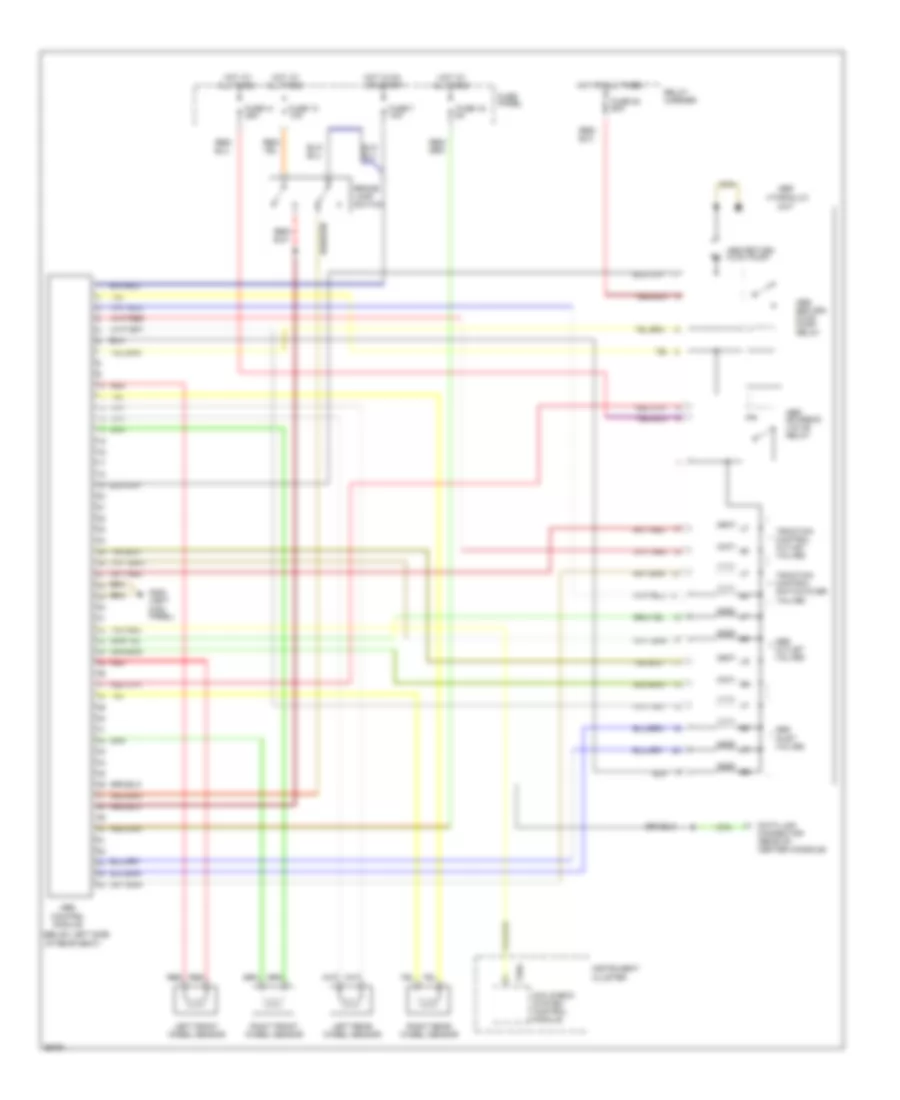
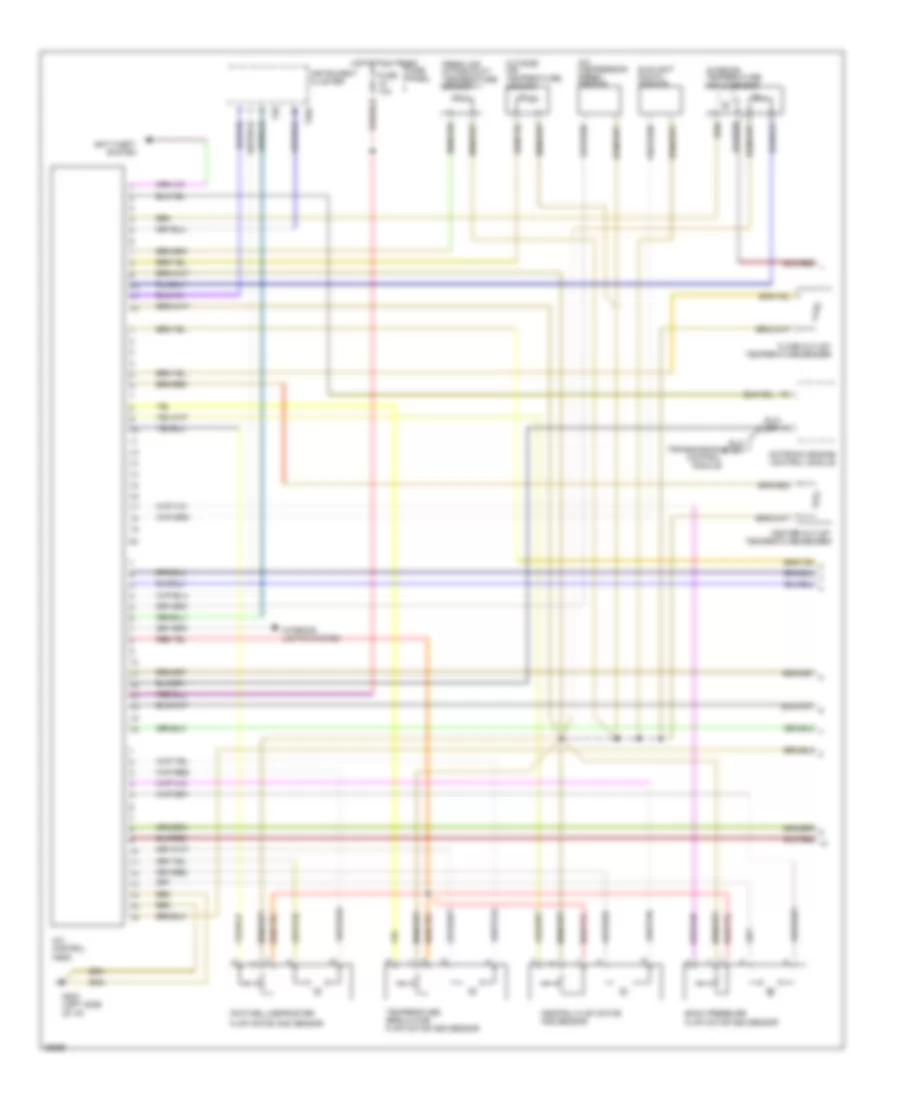
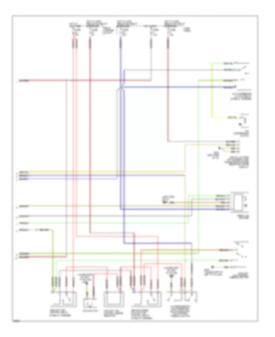
Автомтическая коробка Передач (АКПП) Полная привод (4WD) Блокировка Дифференциала
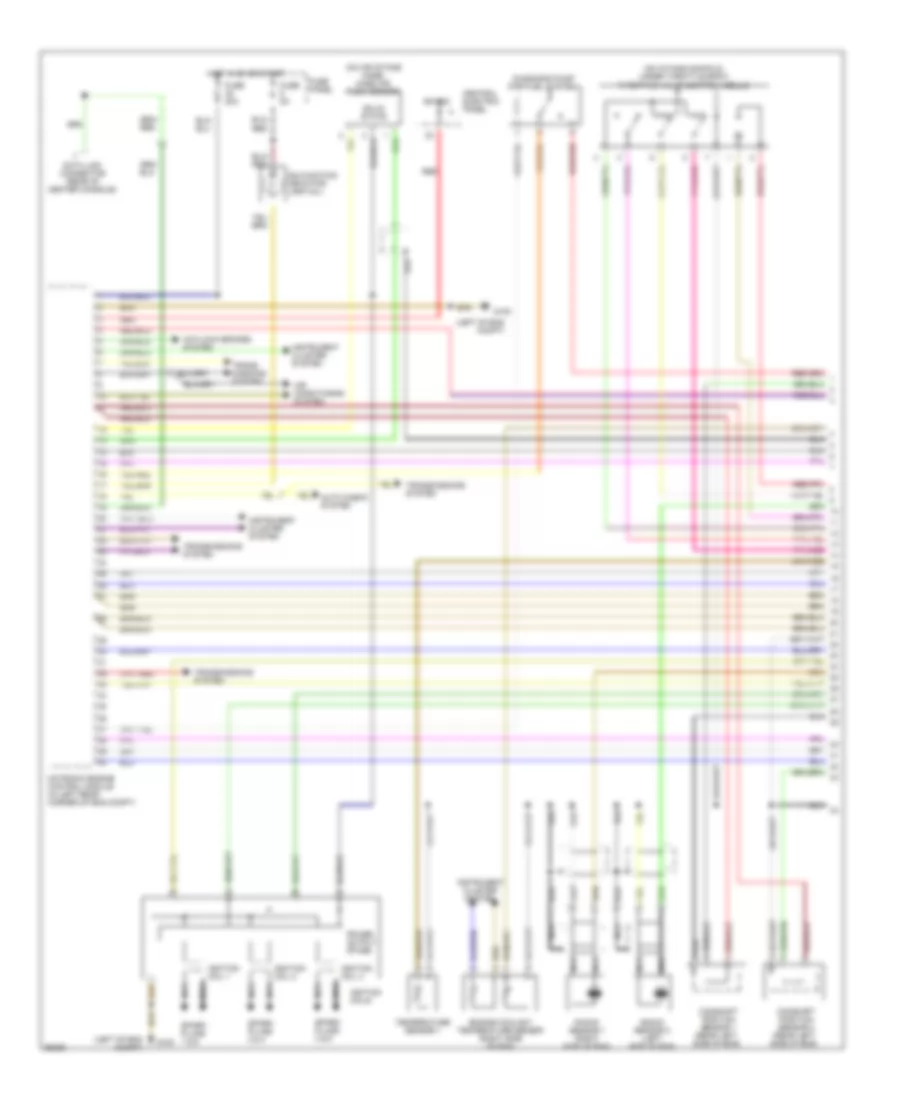
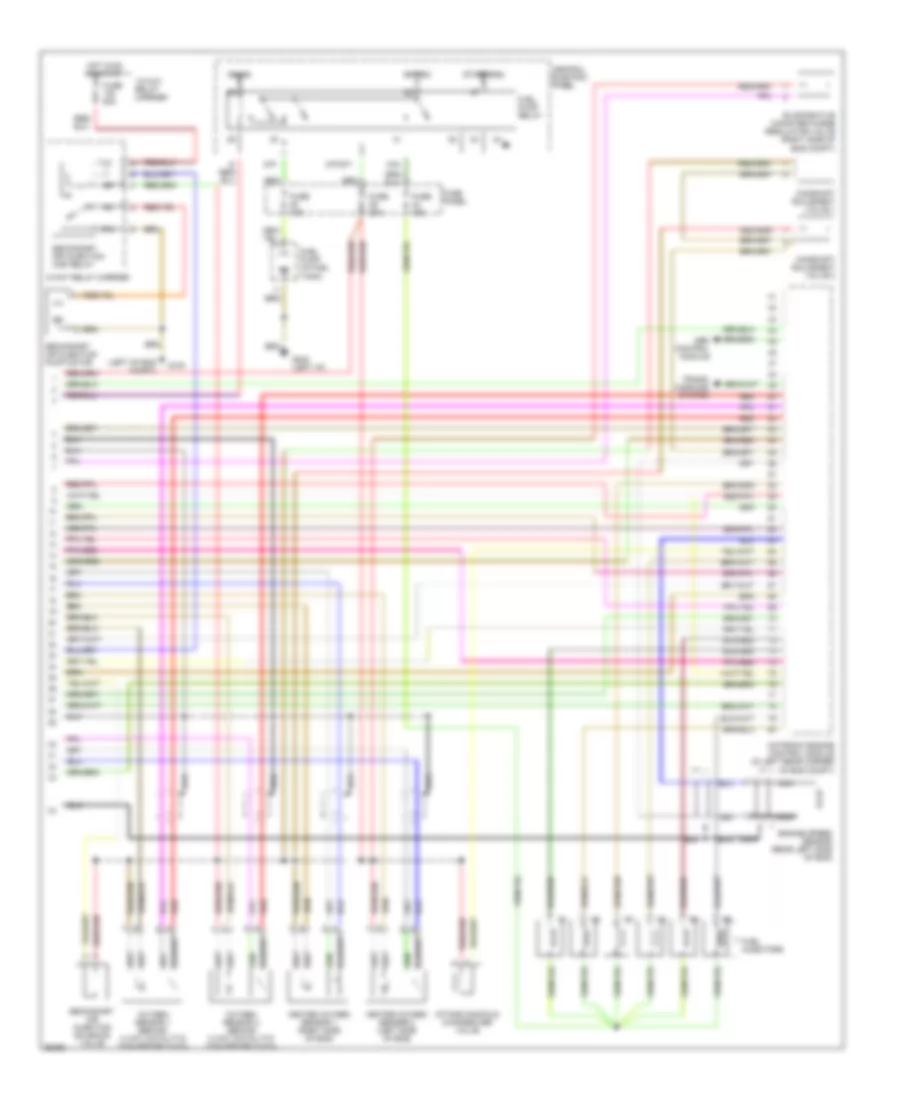
Электросхема автоматической коробки передач АКПП для Audi A4 Quattro 1997
 https://portal-diagnostov.com/license.html
Automotive Electricians Portal FZCO
Automotive Electricians Portal FZCO
https://portal-diagnostov.com/license.html
https://portal-diagnostov.com/license.html
Automotive Electricians Portal FZCO
Automotive Electricians Portal FZCO
Электросхема автоматической коробки передач АКПП для Audi A4 Quattro 1997 - Список элементов:
- (left side of dash)
- (not used)
- 11-13
- 15a
- 231a
- 38-39
- 45-50
- 50a
- 50z
- 56-87
- 87a
- Air conditioning system
- Anti-lock brakes system
- Automatic transmission console light
- Brake light switch (on brake pedal support bracket)
- Central electric panel (left side of dash)
- Central locking/ alarm system/ interior light delay control module (bottom right of luggage compt)
- Cruise control system
- Data link connector (dlc) (rear of center console)
- Engine control module (ecm) (left rear corner of eng compt)
- Exterior lights system
- Fuse 10a
- Fuse 15a
- Fuse panel (left side of dash)
- G102 (left side of eng compt)
- G202
- G202 (left side of dash)
- Generator terminal d+
- Hot at all times
- Hot in on or start
- Ignition switch terminal 50 (hot in start)
- Interior lights system
- Kickdown switch (on throttle housing)
- Multi-function transmission range (tr) switch
- Nca
- Park/ neutral position relay
- Protection diode
- Red
- Selector lever light relay
- Shift lock solenoid
- Solenoid valves
- Starter terminal 50
- Transmission control module (tcm) (under carpet, forward of passenger's seat)
- Transmission fluid temperature sensor
- Transmission input speed sensor
- Transmission range selector lever display or auto check system module
- Transmission vehicle speed sensor
- Valve body
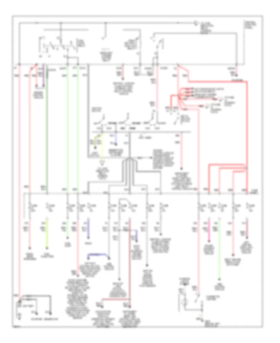
БЛОК ПРЕДОХРАНИТЕЛЕЙ И РЕЛЕ
Электросхема блока предохранителей и реле (1 из 2) для Audi A4 Quattro 1997
Электросхема блока предохранителей и реле (1 из 2) для Audi A4 Quattro 1997 - Список элементов:
- (not used)
- 16a
- 17a
- 28a
- 29a
- 30a
- 31a
- 32a
- 33a
- 34a
- 37a
- 44a
- 50b
- 86s
- 87f
- Abs control module
- Acc
- Acc acc acc acc
- Air bag control module, transmission control module, power window/ sunroof control module, window motors
- Anti-slip control switch, traction control indicator light brake light switch
- Back-up light switch, automatic transmission console light
- Battery
- Central electric panel
- Central locking/ alarm system/ interior light delay control module
- Central locking/ alarm system/ interior light delay control module, door lock switch
- Cigarette lighter
- Daytime running lights switch-on relay
- Engine control module
- Evap canister purge regulator valve, camshaft adjustment valves, secondary air injection solenoid valve, oxygen sensors secondary air injection relay, fuel system diagnostic pump, wastegate bypass regulator valve mass air flow sensor
- Fuel injectors
- Fuel pump
- Fuel pump relay
- Fuse 10a
- Fuse 15a
- Fuse 20a
- Fuse 30a
- Fuse 5a
- Fuse panel
- G202 (behind left side of i/p)
- Generator
- Generator, instrument cluster
- Headlight dimmer/ flasher switch
- Headlight washer system relay
- Ignition coils, engine control module, mass air flow sensor
- Ignition switch
- Instrument cluster, radio, central locking/alarm system/interior light delay control module
- Instrument cluster, rear lamp control module, a/c control head, interior temp sensor fan
- Interior lights system
- Key-in ignition switch
- Left heated door lock control module
- Light switch
- Malfunction indicator lamp (mil), mirror adjustment switch, seat heat regulating switches
- Off
- Park/ neutral position relay
- Power sunroof control module
- Radio
- Radio, rear speakers
- Red
- Run
- Run run run run
- S1/50z
- S2/87f
- S3/15
- S3/s
- S4/4
- S4/50z
- S4/b
- S6/50a
- Seat heater regulating switches
- Shift lock solenoid, cruise control switch
- Start
- Start start start start
- Starter
- To fuse (diagram 2 of 2)
- To load reduction relay (diagram 2 of 2)
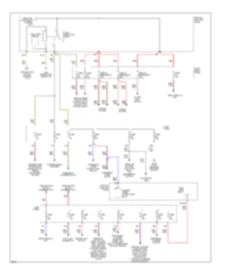
Электросхема блока предохранителей и реле (2 из 2) для Audi A4 Quattro 1997
Электросхема блока предохранителей и реле (2 из 2) для Audi A4 Quattro 1997 - Список элементов:
- 12a
- 13a
- 14a
- 15a
- 24a
- 25a
- 26a
- 38a
- 39a
- 40a
- 41a
- 75a
- 75x
- A/c control head
- Abs hydraulic unit
- Brake light switch
- Central electric panel
- Central locking/ alarm system/ interior lights delay control module, door lock switch ultra sound sensor control module
- Circuit breaker 37 30a
- Circuit breaker 43 30a
- Circuit breaker 44 30a
- Data link connector
- Dual horn relay
- Emergency flasher switch
- Fresh air blower, a/c clutch relay, a/c refrigerant switch
- From fuel pump relay (diagram 1 of 2)
- From ignition switch (diagram 1 of 2)
- Fuse 10a
- Fuse 15a
- Fuse 25a
- Fuse 30a
- Fuse 40a
- Fuse 5a
- Fuse panel
- Fuse/ relay panel
- G202 (behind left side of i/p)
- Instrument cluster, selector lever light relay, transmission control module
- Load reduction relay
- Power seat switch
- Rear fog light switch, front interior light, central locking/alarm system/interior light delay control module, reading lights make-up mirror lights
- Rear window defogger switch
- Red
- S1/30ah
- S1/31
- S1/75
- Second speed coolant fan control relay, coolant fan control relay
- Temperature/ transmission range switch, mirror adjustment motors
- Washer nozzle heaters
- Washer/ wiper intermittent relay
- Window motors
- Windshield wiper intermittent switch
- Windshield wiper motor
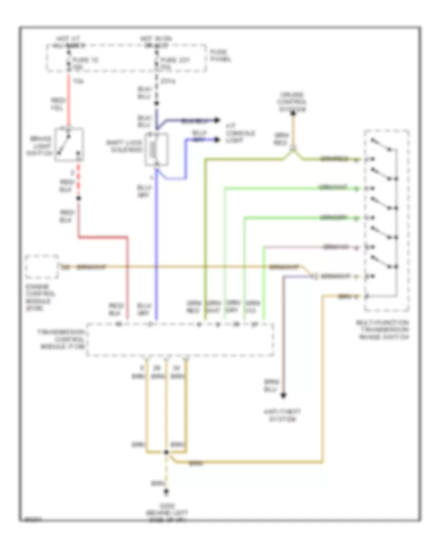
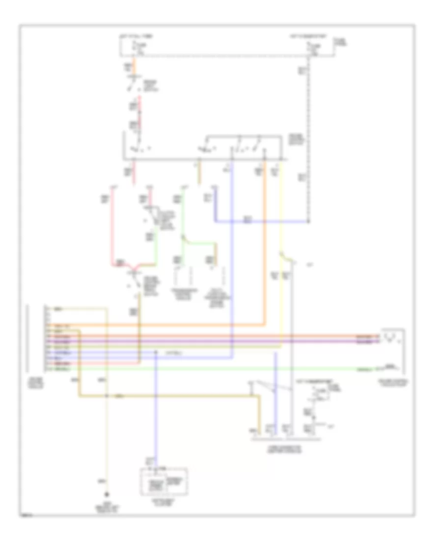
БЛОКИРОВКИ СЕЛЕКТОРА СТОЯНОЧНЫЙ ТОРМОЗ
Электросхема блокировки селектора для Audi A4 Quattro 1997
Электросхема блокировки селектора для Audi A4 Quattro 1997 - Список элементов:
- 13a
- 231a
- A/t console light
- Anti-theft system
- Brake light switch
- Cruise control system
- Engine control module (ecm)
- Fuse 13 10a
- Fuse 231 15a
- Fuse panel
- G202 (behind left side of i/p)
- Hot at all times
- Hot in on or acc
- Multi-function transmission range switch
- Shift lock solenoid
- Transmission control module (tcm)
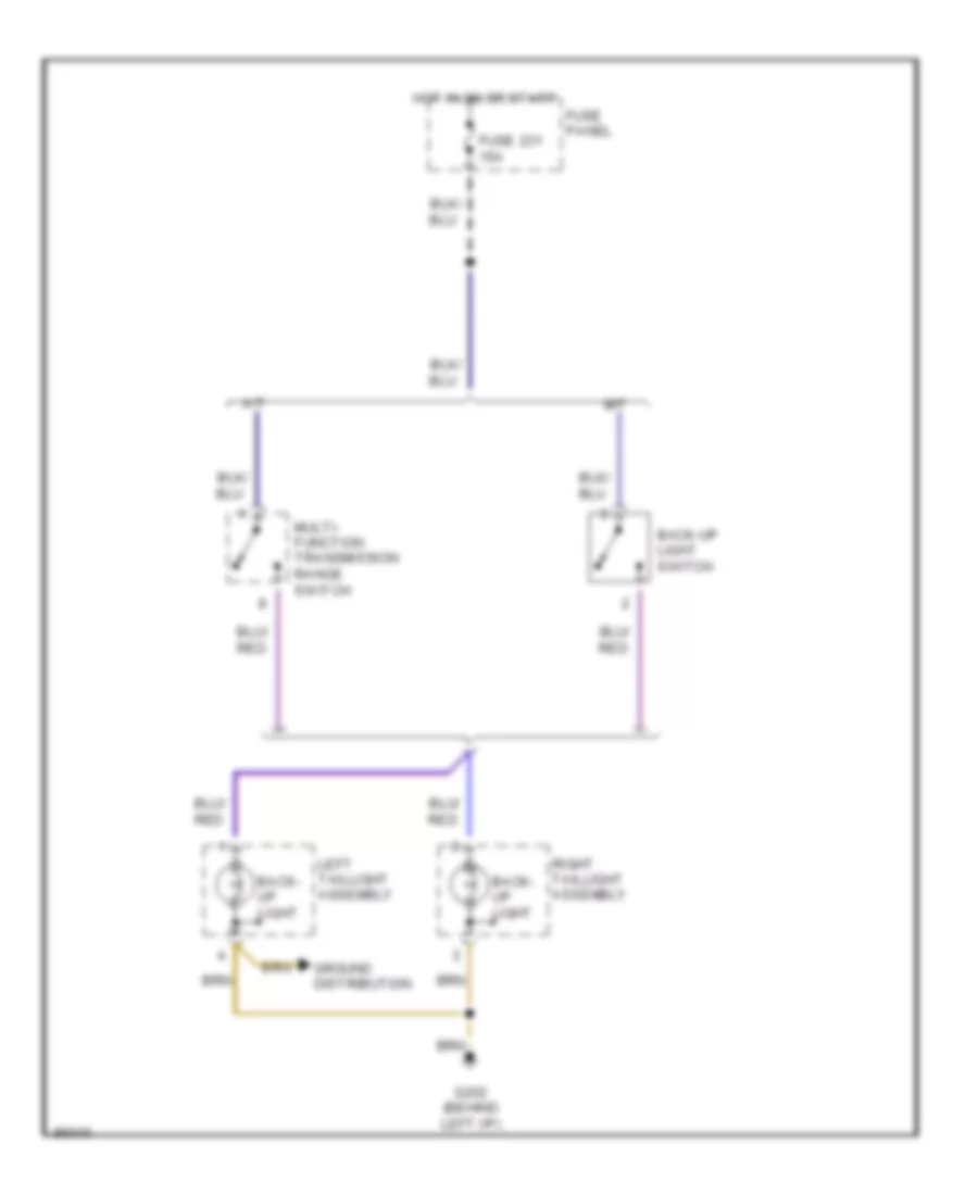
ВНЕШНЕЕ ОСВЕЩЕНИЕ
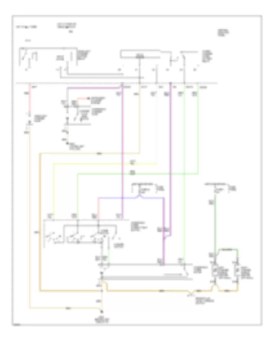
Электросхема заднего хода для Audi A4 Quattro 1997
Электросхема заднего хода для Audi A4 Quattro 1997 - Список элементов:
- A/t
- Back- up light
- Back-up light switch
- Fuse 231 15a
- Fuse panel
- G202 (behind left i/p)
- Ground distribution
- Hot in on or start
- Left taillight assembly
- M/t
- Multi- function transmission range switch
- Right taillight assembly
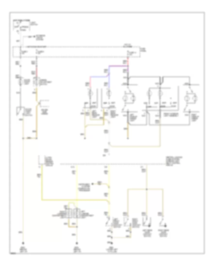
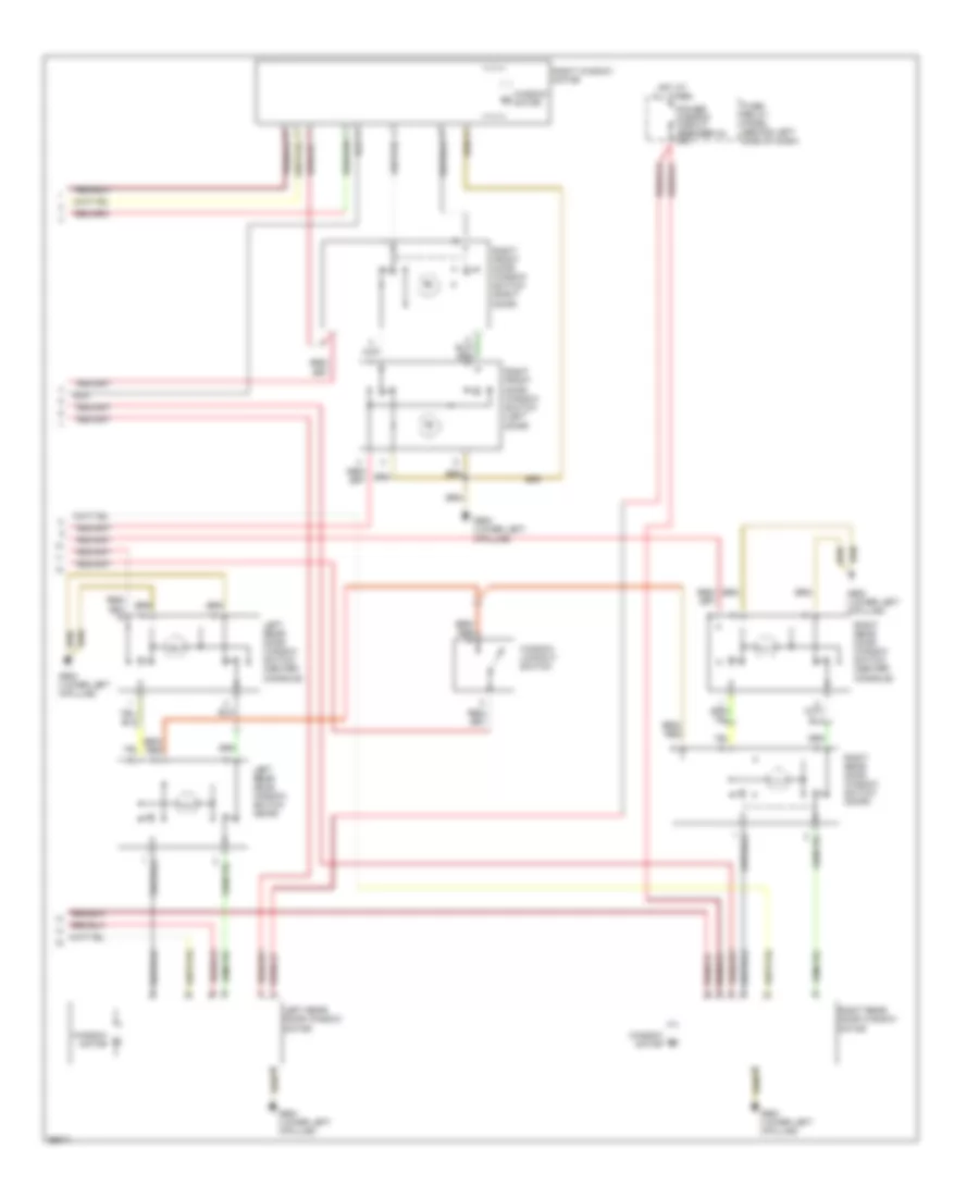
Электросхема внешнего освещения, С DRL для Audi A4 Quattro 1997
Электросхема внешнего освещения, С DRL для Audi A4 Quattro 1997 - Список элементов:
- (behind left i/p)
- 49a
- B/2
- B/3
- Brake light switch
- Central electric panel
- Central locking/ alarm system/ interior light delay control module
- Daytime running lights switch- on relay
- Emergency flasher relay/ switch
- Fuse
- Fuse 10a
- Fuse 15a
- Fuse 5a
- Fuse panel
- G202
- G202 (behind left i/p)
- G900 (lower left a pillar)
- G901 (lower right a pillar)
- Head
- High- mount brake lights
- Hot at all times
- Hot in acc or run
- Hot w/ load reduction relay energized
- Instrument cluster
- Interior lights system
- L30
- Left front park/ turn light
- Left front side turn light
- Left taillight assembly
- Left turn ind.
- License plate lights
- Light switch
- Off
- Park
- Red
- Right front park/ turn light
- Right front side turn light
- Right taillight assembly
- Right turn ind.
- Solid state
- Stop
- System
- T26
- T26a
- Tail
- Turn
- Turn signal switch
- Warnings
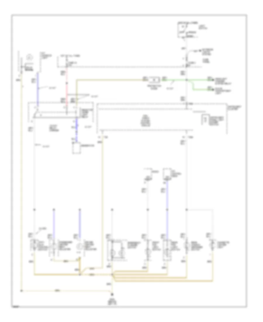
Электросхема внешнего освещения, без DRL для Audi A4 Quattro 1997
Электросхема внешнего освещения, без DRL для Audi A4 Quattro 1997 - Список элементов:
- 49a
- B/2
- B/3
- Brake light switch
- Central electric panel
- Central locking/ alarm system/ interior light delay control module
- Emergency flasher relay/ switch
- Fuse 10a
- Fuse 15a
- Fuse 5a
- Fuse panel
- G202 (behind left i/p)
- G900 (lower left a pillar)
- G901 (lower right a pillar)
- Head
- High- mount brake lights
- Hot at all times
- Hot in acc or run
- Instrument cluster
- Interior lights system
- L30
- Left front park/ turn light
- Left front side turn light
- Left taillight assembly
- Left turn ind.
- License plate lights
- Light switch
- Off
- Park
- Red
- Right front park/ turn light
- Right front side turn light
- Right taillight assembly
- Right turn ind.
- Solid state
- Stop
- System
- T26
- T26a
- Tail
- Turn
- Turn signal switch
- Warnings
ВНУТРЕННЕЕ ОСВЕЩЕНИЕ
Электросхема подсветки для Audi A4 Quattro 1997
Электросхема подсветки для Audi A4 Quattro 1997 - Список элементов:
- A/12
- B/6
- C/6
- C/7
- Central locking/ alarm system/ interior light delay control module
- Door
- Driver side mirror
- Exterior lights system
- Front interior light assembly
- Fuse 14 10a
- Fuse 3 5a
- Fuse 5 5a
- Fuse panel
- G202 (behind left i/p)
- G900 (lower left "a" pillar)
- Glove compt light
- Glove compt light switch
- Head
- Hot at all times
- Hot in run or start
- Instrument cluster combination processor
- Left front door contact switch
- Left luggage compartment light
- Left make-up mirror light
- Left rear door contact switch
- Left rear reading light
- Light switch
- Mirror adjustment switch
- Nca
- Off
- Park
- Right front door contact switch
- Right luggage compartment light
- Right make-up mirror light
- Right rear door contact switch
- Right rear reading light
- Ultra- sound sensor control module
Электросхема подсветки приборов для Audi A4 Quattro 1997
Электросхема подсветки приборов для Audi A4 Quattro 1997 - Список элементов:
- 13-way relay carrier
- A/c control head
- A/t console light
- Anti- slip control switch
- Cigarette lighter light
- Dim input
- Driver heated seat adjuster
- Emergency flasher switch
- Exterior lights system
- Front fog light switch
- Fuse 15 10a
- Fuse 3 5a
- Fuse panel
- G202 (behind left i/p)
- Generator
- Glove compartment light
- Head
- Headlight washer system relay
- Hot at all times
- Instrument cluster
- Instrument panel light dimmer switch
- Light switch
- Mini- check system control module
- Off
- Park
- Passenger heated seat adjuster
- Protection diode
- Radio
- Rear fog light switch
- Rear window defogger switch
- Selector lever light relay
- Solid state
- T26
- T26a
- W/ a/t
- W/ asc
ЗАЗЕМЛЕНИЕ ПОДКЛЮЧЕНИЕ МАССЫ
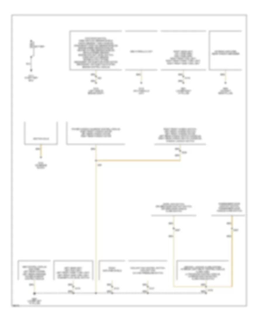
Электросхема подключение массы заземления (1 из 2) для Audi A4 Quattro 1997
Электросхема подключение массы заземления (1 из 2) для Audi A4 Quattro 1997 - Список элементов:
- Abs control module, amplifier, left rear woofer, left rear midrange, power sunroof control module
- Abs hydraulic unit
- Antenna amplifier, rear window defogger
- Battery
- Central locking/ alarm system/ interior light delay control module, alarm horn, ultra-sound control module, interior monitor switch, alarm hood switch
- Coolant fan control switch, coolant fan, a/c high pressure switch
- Door lock switch, driver's door contact switch, driver's door handle alarm switch
- G104 (left side of engine compt)
- G111 (in battery box)
- G116 (on hydraulic unit)
- G132 (on engine block)
- G900 (lower left "a" pillar)
- G901 (lower right "a" pillar)
- G905 (on right rear pillar)
- Ignition coils
- Kick down switch, mass air flow sensor shield, knock sensor 1 and 2 shields, crankshaft position sensor shields, engine speed sensor shields, heated oxygen sensor shields, vehicle speed sensor, engine coolant level switch, mass air flow sensor, power output stage, secondary air injection pump motor, secondary air injection system, engine control module
- Left headlight, left fog light, left front park/ turn light, left front side turn light, washer fluid level switch
- Passenger's door contact switch, passenger's door handle alarm switch
- Power window/ sunroof control module, right front window motor left rear window motor, right rear window motor
- Radio, amplifier shield
- Right front window switch, left front window switch, left front window motor, left rear window switch (console), right rear window switch (console), window lockout switch
- Right headlight, low tone horn, high tone horn, right front fog light, right front park/ turn light, right front side turn light
- S106
- S127
- S133
- S176
- S179
- S205
- S267
- S83
- S89
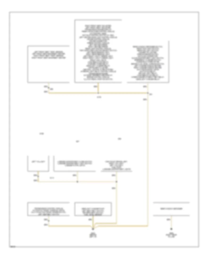
Электросхема подключение массы заземления (2 из 2) для Audi A4 Quattro 1997
Электросхема подключение массы заземления (2 из 2) для Audi A4 Quattro 1997 - Список элементов:
- G202 (behind left i/p)
- G905 (right rear pillar)
- Headlight washer pump, left seat belt switch, driver's seat switch, fuel level sensor
- High mount brake light, right taillight, left taillight, fuel pump, luggage compartment lights
- Left front seat temp. sensor, left front seat backrest heater, right front seat temp. sensor, right front seat backrest heater
- Left taillight
- Luggage compartment alarm switch, luggage compartment light switch, license plate lights
- Rear window defogger
- Rear window defogger switch, front fog light switch, rear fog light switch, cigarette lighter, parking brake switch, datalink connector, glove compartment light switch, emergency flasher switch, windshield wiper motor, brake fluid level warning switch, left washer nozzle heater, right washer nozzle heater, daytime running lights switch-on relay, driving light relay, load reduction relay, wiper/washer intermittent relay, headlight washer relay
- Right front seat adjuster, left front seat adjuster, transmission range display, fresh air blower control module, a/c control head, anti-slip control switch (w/ asc), left heated door lock control module, cruise control module, cruise connector, airbag control module, left heated mirror, right heated mirror, rear lamp control module, trip computer function select switch, left rear reading light, right rear reading light, left front vanity mirror light, right front vanity mirror light, front map lights, load reduction relay, washer/ wiper relay, headlight washer relay, instrument cluster, central locking/ alarm system/ interior light delay control module transmission range/ outside temperature display, engine control module, clutch pedal position switch
- S114
- S135
- S196
- S81
- S86
- S87
- S96
- Transmission control module, automatic trans. console lights, multi-function trans. range switch, left seatbelt switch
Звуковой сигнал Гудок
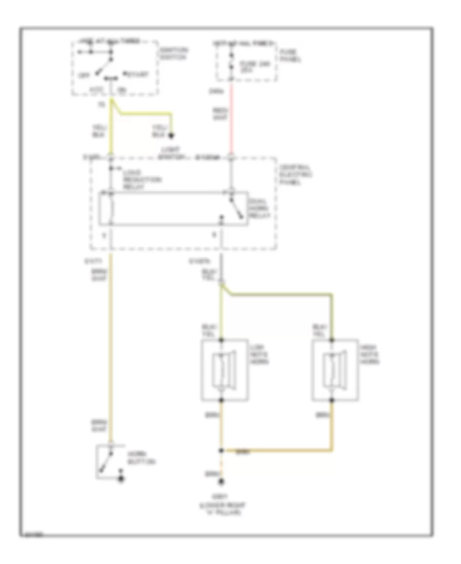
Электросхема звукового сигнал Гудка для Audi A4 Quattro 1997
Электросхема звукового сигнал Гудка для Audi A4 Quattro 1997 - Список элементов:
- (lower right "a" pillar)
- 240a
- Acc
- Central electric panel
- Dual horn relay
- Fuse 240 25a
- Fuse panel
- G901
- High note horn
- Horn button
- Hot at all times
- Ignition switch
- Light switch
- Load reduction relay
- Low note horn
- Off
- S1/30ah
- S1/71
- S1/75
- S1/87h
- Start
Магнитола Мультимедия
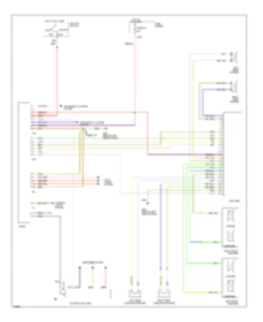
Электросхема магнитолы для Audi A4 Quattro 1997
Электросхема магнитолы для Audi A4 Quattro 1997 - Список элементов:
- 20a
- 237a
- 86s
- Acc
- Amplifier
- Antenna amplifier
- Auto check system
- Defogger system
- Fuse 237
- Fuse holder
- G201 (behind left side of dash)
- Hot at all times
- Ignition switch
- Instrument cluster system
- Interior lights system
- Left front speaker
- Left rear midrange speaker
- Left rear woofer
- Lock
- Midrange
- Nca
- Radio
- Red
- Right front speaker
- Right rear midrange speaker
- Right rear woofer
- Run
- Start
- T1i
- T6m
- T6x
- T8a
- Woofer
Подогрев стекол и зеркал
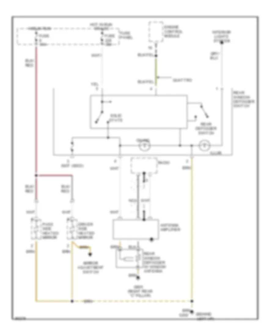
Электросхема подогрева стекол и зеркал, С Усилитель Антенны для Audi A4 Quattro 1997
Электросхема подогрева стекол и зеркал, С Усилитель Антенны для Audi A4 Quattro 1997 - Список элементов:
- (behind left i/p)
- (not used)
- Antenna amplifier
- Driver side heated mirror
- Engine control module
- Fuse 30a
- Fuse panel
- G202
- G905 (right rear "c" pillar)
- Hot in run
- Illum.
- Interior lights system
- Mirror adjustment switch
- Nca
- On ind.
- Or acc
- Pass. side heated mirror
- Quattro
- Radio
- Rear defogger switch
- Rear window defogger switch
- Rear window defogger w/ window antenna
- Solid state
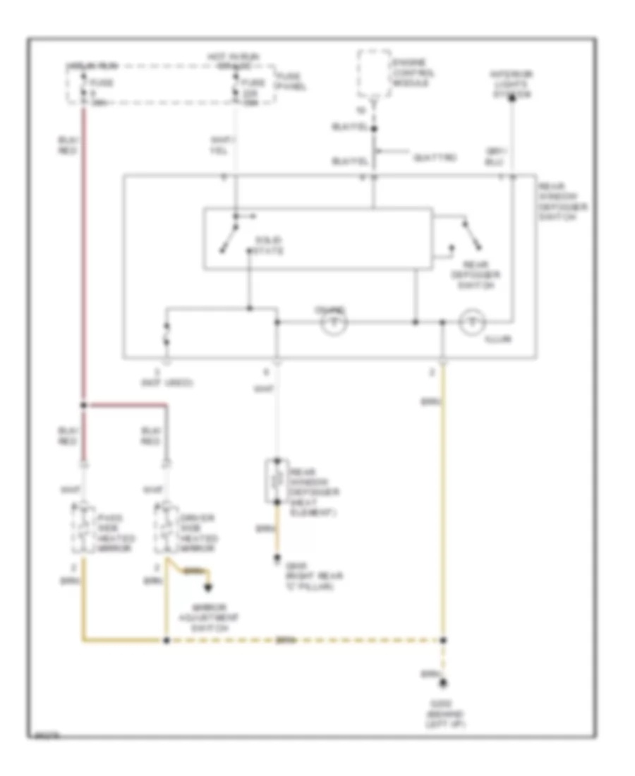
Электросхема подогрева стекол и зеркал, без Усилитель Антенны для Audi A4 Quattro 1997
Электросхема подогрева стекол и зеркал, без Усилитель Антенны для Audi A4 Quattro 1997 - Список элементов:
- (not used)
- Driver side heated mirror
- Engine control module
- Fuse 30a
- Fuse panel
- G202 (behind left i/p)
- G905 (right rear "c" pillar)
- Hot in run
- Illum.
- Interior lights system
- Mirror adjustment switch
- On ind.
- Or acc
- Pass. side heated mirror
- Quattro
- Rear defogger switch
- Rear window defogger (heat element)
- Rear window defogger switch
- Solid state
ПОДУШКИ БЕЗОПАСНОСТИ AIR BAG
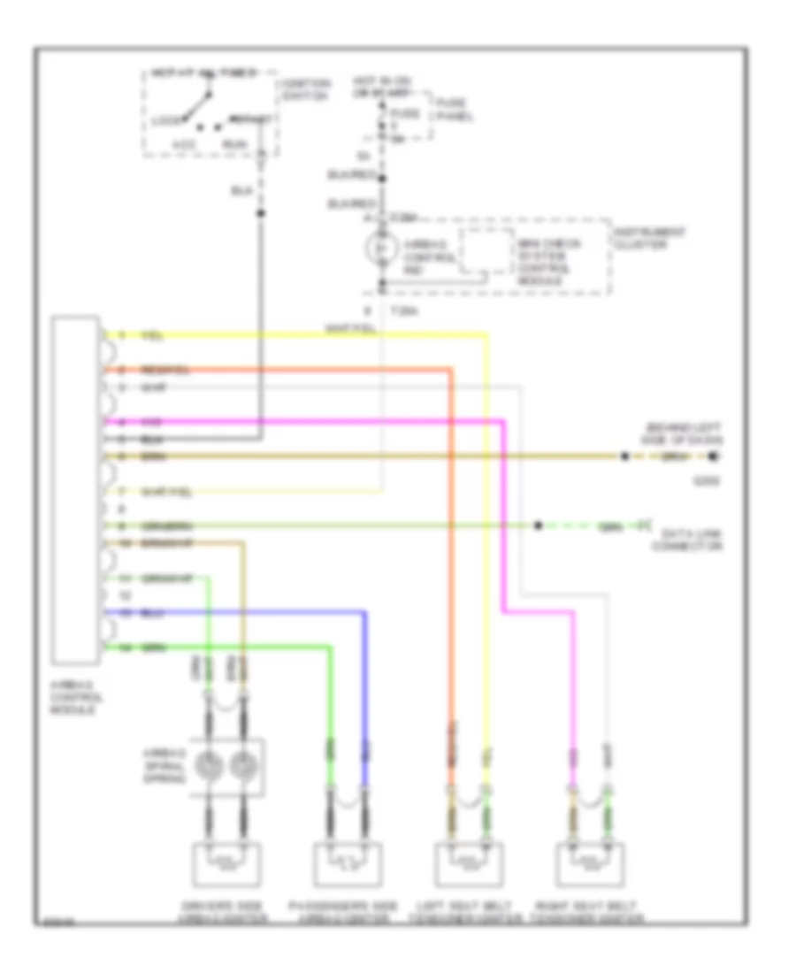
Электросхема подушек безопасности SRS AirBag для Audi A4 Quattro 1997
Электросхема подушек безопасности SRS AirBag для Audi A4 Quattro 1997 - Список элементов:
- (behind left side of dash)
- Acc
- Airbag control ind
- Airbag control module
- Airbag spiral spring
- Data link connector
- Driver's side airbag igniter
- Fuse 5a
- Fuse panel
- G202
- Hot at all times
- Hot in on or start
- Ignition switch
- Instrument cluster
- Left seat belt tensioner igniter
- Lock
- Mini check system control module
- Nca
- Passenger's side airbag igniter
- Right seat belt tensioner igniter
- Run
- Start
- T26a
ПРЕДУПРЕЖДАЮЩИЕ СИСТЕМЫ
Электросхема предупреждающей системы для Audi A4 Quattro 1997
Электросхема предупреждающей системы для Audi A4 Quattro 1997 - Список элементов:
- (behind left side of i/p)
- (lower left "a" pillar)
- 15a
- 86s
- A/c control
- Abs control module
- Driver's door contact switch
- Driver's seat belt switch
- Engine control module (ecm)
- Engine coolant level switch
- Engine coolant temperature sensor (ect)
- Engine oil pressure
- Engine oil temp sensor
- Fuel level sensor
- Fuse 15 10a
- Fuse 3 5a
- Fuse panel
- G202
- G202 (left side of i/p)
- G900
- Head
- Headlight switch
- Headlight system
- Hot at all times
- Hot w/ park or headlights on
- Ignition switch
- Instrument cluster
- Interior lights system
- Key switch
- Mini check system control module
- Nca
- Red
- Switch
- T26
- T26-1
- T26-12
- T26-16
- T26-18
- T26-19
- T26-20
- T26-25
- T26-26
- T26-3
- T26-4
- T26-5
- T26-6
- T26-7
- T26-8
- T26-9
- T26a
- T26a-11
- T26a-12
- T26a-13
- T26a-14
- T26a-18
- T26a-19
- T26a-20
- T26a-23
- T26a-24
- T26a-26
- T4a
- T4a-1
- Vehicle speed sensor
- Warning buzzer
ПРИБОРНАЯ ПАНЕЛЬ
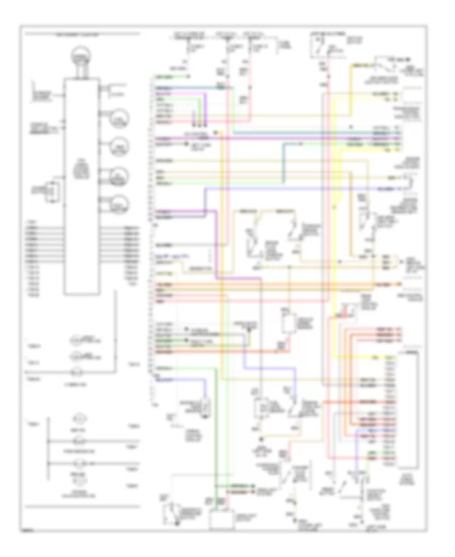
Электросхема панели приборов для Audi A4 Quattro 1997
Электросхема панели приборов для Audi A4 Quattro 1997 - Список элементов:
- (behind left side of i/p)
- (left side of i/p)
- (lower left "a" pillar)
- 15a
- 86s
- A/c control head
- Abs control module
- Abs ind.
- Air bag malifunction ind.
- Airbag control module
- Auto check system
- Brake fluid level warning switch
- Clock
- Console inst lighting booster
- Dimmer switch
- Driver's door contact switch
- Driver's seat belt switch
- Engine control module (ecm)
- Engine coolant level switch
- Engine coolant temperature sensor (ect)
- Engine oil pressure
- Engine oil temp sensor
- Fuel gauge
- Fuel level sensor
- Function select switch
- Fuse 15 10a
- Fuse 3 5a
- Fuse 5 5a
- Fuse panel
- G202
- G202 (left side of i/p)
- G900
- G900 (lower left "a" pillar)
- Gen ind.
- Generator
- Headlight switch
- Headlight system
- Headlights system
- Hi beam ind.
- Hot at all times
- Hot w/ park or headlights on
- Ignition switch
- Instrument cluster
- Interior lights system
- Key switch
- Left turn ind.
- Left turn lights
- Mini check system control module
- Nca
- Oil press gauge
- Park brake ind.
- Parking brake switch
- Radio
- Rear lamp control module
- Red
- Reset button
- Right turn ind.
- Right turn lights
- Speed- ometer
- Switch
- T20/1
- T20/10
- T20/11
- T20/12
- T20/13
- T20/14
- T20/15
- T20/16
- T20/17
- T20/18
- T20/19
- T20/2
- T20/20
- T20/3
- T20/4
- T20/5
- T20/6
- T20/7
- T20/8
- T20/9
- T26
- T26-1
- T26-12
- T26-13
- T26-16
- T26-18
- T26-19
- T26-20
- T26-25
- T26-26
- T26-3
- T26-4
- T26-5
- T26-6
- T26-7
- T26-8
- T26-9
- T26a
- T26a-11
- T26a-12
- T26a-13
- T26a-14
- T26a-18
- T26a-19
- T26a-20
- T26a-21
- T26a-22
- T26a-23
- T26a-24
- T26a-26
- T26a-4
- T26a-6
- T26a-7
- T26a-8
- T26a-9
- T4a
- T4a-1
- Tach- ometer
- Temp gauge
- Transmission control module (tcm)
- Trip computer control switch
- Vehicle speed sensor
- Warning buzzer
- Washer fluid level switch
- Windshield washer pump
ПРИВОД ЗЕРКАЛ
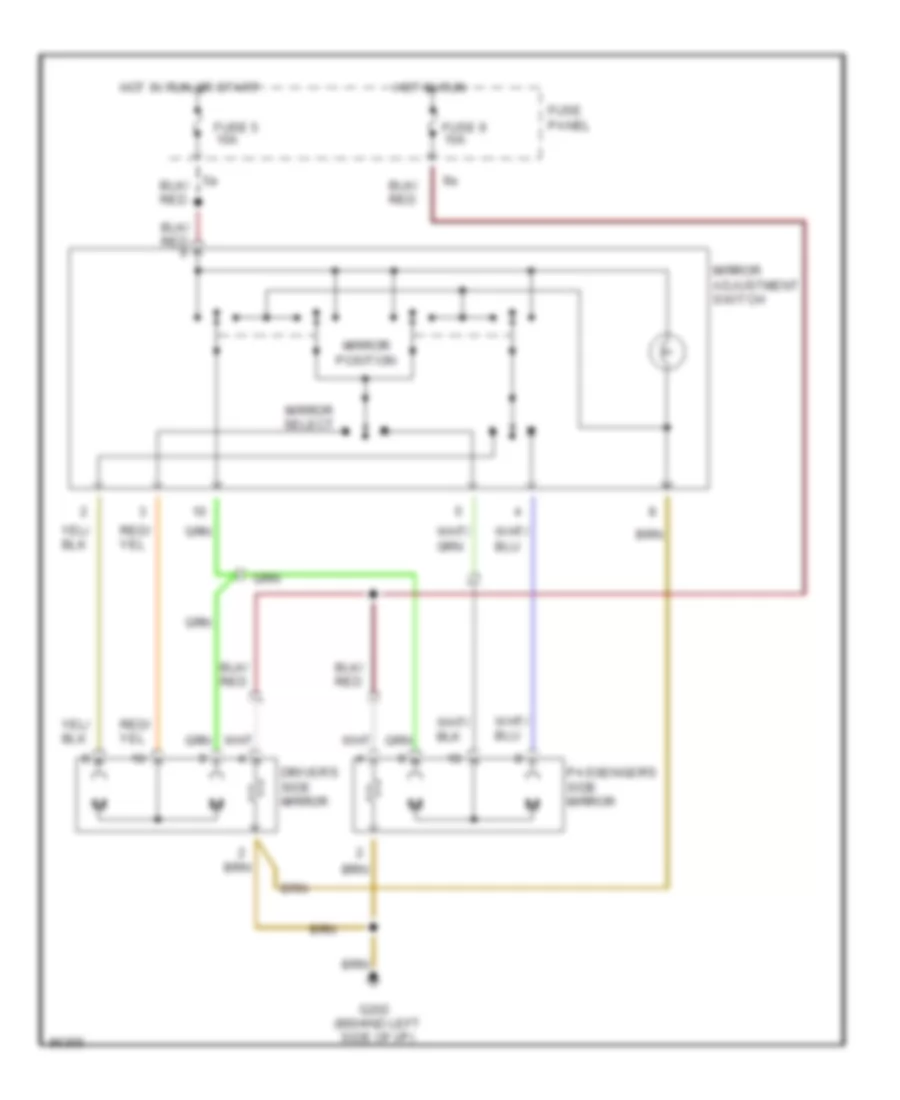
Электросхема привода зеркал для Audi A4 Quattro 1997
Электросхема привода зеркал для Audi A4 Quattro 1997 - Список элементов:
- Driver's side mirror
- Fuse 5 10a
- Fuse 9 10a
- Fuse panel
- G202 (behind left side of i/p)
- Hot in run
- Hot in run or start
- Mirror adjustment switch
- Mirror position
- Mirror select
- Passenger's side mirror
ПРИВОД ЛЮКА И КРЫШИ
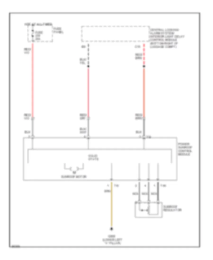
Электросхема привода люка для Audi A4 Quattro 1997
Электросхема привода люка для Audi A4 Quattro 1997 - Список элементов:
- C15
- Central locking/ alarm system/ interior light delay control module (bottom right of luggage compt)
- Fuse 20a
- Fuse panel
- G900 (lower left "a" pillar)
- Hot at all times
- Nca
- Power sunroof control module
- Solid state
- Sunroof motor
- Sunroof regulator
- T4k
- T6i
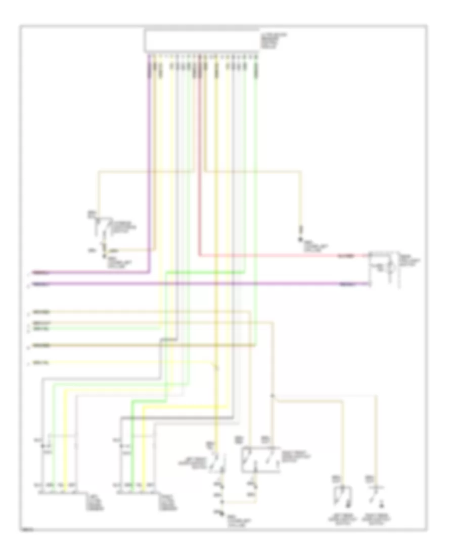
ПРИВОД СТЕКЛОПОДЪЕМНИКОВ
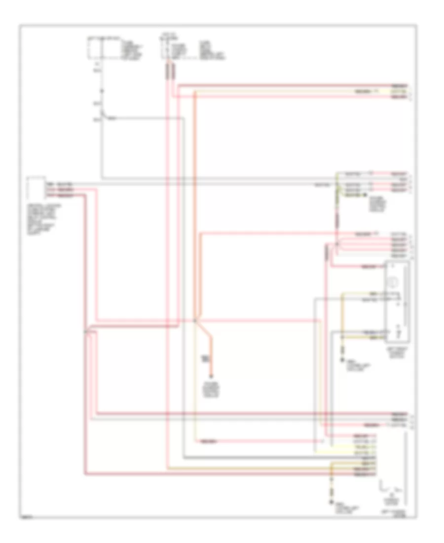
системная монтажная схема окна со стеклоподъемником (схема A4 1 из 2) для Audi A4 Quattro 1997
системная монтажная схема окна со стеклоподъемником (схема A4 1 из 2) для Audi A4 Quattro 1997 - Список элементов:
- A11
- All times
- C15
- Central locking/ alarm system/ interior light delay control module (bottom right of luggage compt)
- Fuse assembly (behind left side of dash)
- Fuse/ relay panel (behind left side of dash)
- G900 (lower left a-pillar)
- Hot at
- Hot in on or acc
- Left front window switch
- Left window motor
- Power sunroof control module
- Power window fuse 37 30a
- Window motor
системная монтажная схема окна со стеклоподъемником (схема A4 2 из 2) для Audi A4 Quattro 1997
системная монтажная схема окна со стеклоподъемником (схема A4 2 из 2) для Audi A4 Quattro 1997 - Список элементов:
- All times
- Fuse/ relay panel (behind left side of dash)
- G900 (lower left a-pillar)
- Hot at
- Left rear door window motor
- Left rear door window switch (center console)
- Left rear door window switch (door)
- Power window circuit breaker 43 30a
- Right front door window switch (left door)
- Right front door window switch (right door)
- Right rear door window motor
- Right rear door window switch (center console)
- Right rear door window switch (door)
- Right window motor
- Window lockout switch
- Window m motor
- Window motor
Противоугонная система Сигнализация
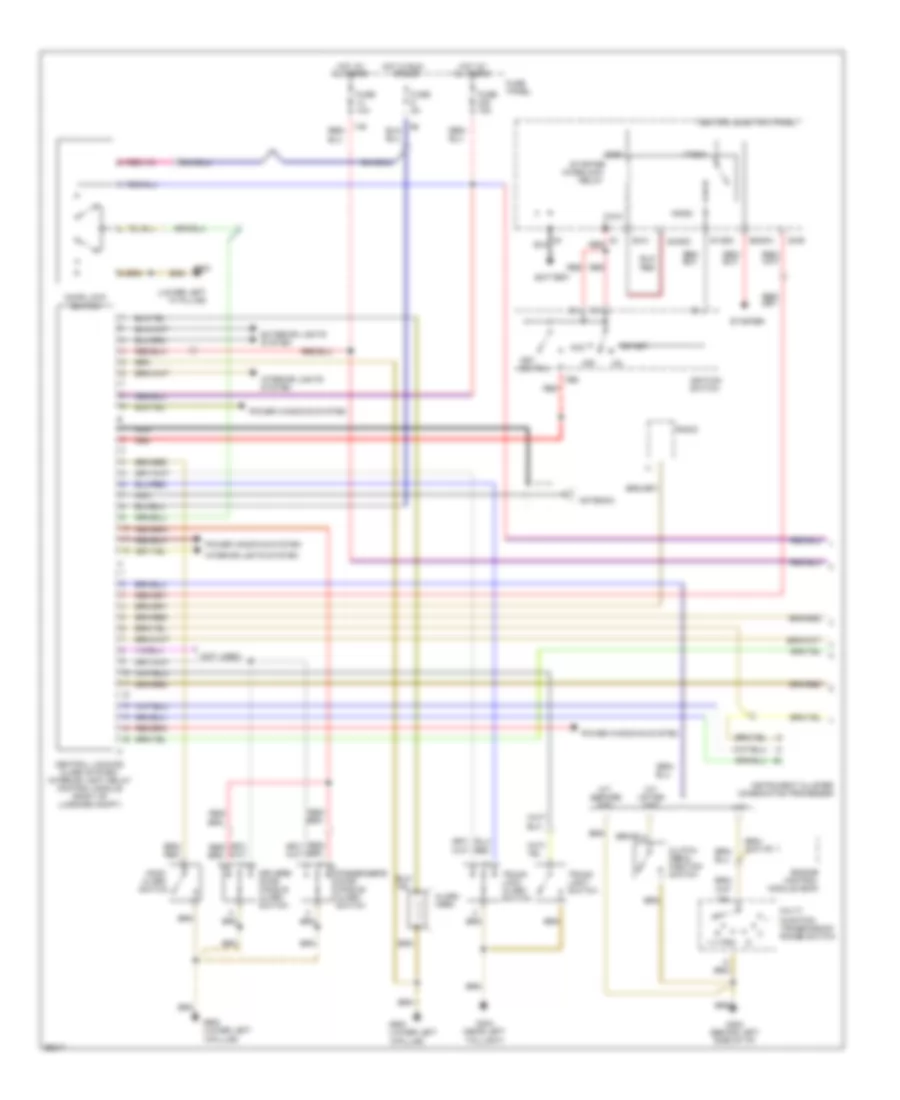
противоугонная и центральная схема захвата (1 из 2) для Audi A4 Quattro 1997
противоугонная и центральная схема захвата (1 из 2) для Audi A4 Quattro 1997 - Список элементов:
- (lower left
- (lower left "a" pillar)
- (not used)
- 14a
- 15/a
- 17/50a
- 19/50z
- 20/b
- 7/b
- 86s
- A-pillar)
- A/t
- Acc
- Alarm
- Alarm switch
- All times
- Antenna
- Battery
- Central electric panel
- Central locking/ alarm system/ interior light delay control module (right of luggage compt)
- Clutch pedal position switch
- Door lock switch
- Driver's door handle alarm switch
- Engine control module (ecm)
- Exterior lights system
- Function transmission range switch
- Fuse 10a
- Fuse 15a
- Fuse 5a
- Fuse panel
- G202 (behind left side of i/p)
- G404 (near left
- G900
- Hood
- Horn
- Hot at
- Hot in run
- Ignition switch
- Instrument cluster combination processor
- Interior lights system
- Interlock
- Key switch
- M/t (after 5/97)
- M/t (before 5/97)
- Multi-
- Nca
- Off
- Or acc
- Passenger's door handle alarm switch
- Power windows system
- Radio
- Red
- Relay
- S1/50z
- S4/50z
- S4/a
- S4/b
- S6/50a
- Start
- Starter
- Taillight)
- Trunk light switch
- Trunk lock alarm switch
противоугонная и центральная схема захвата (2 из 2) для Audi A4 Quattro 1997
противоугонная и центральная схема захвата (2 из 2) для Audi A4 Quattro 1997 - Список элементов:
- (lower left
- A-pillar)
- Alarm ind
- G900
- G900 (lower left a-pillar)
- Interior monitoring switch
- Left front door contact switch
- Left rear door contact switch
- Left ultra sound sensor
- Nca
- Rear fog loght switch
- Right front door contact switch
- Right rear door contact switch
- Right ultra sound sensor
- Ultra sound sensors control module
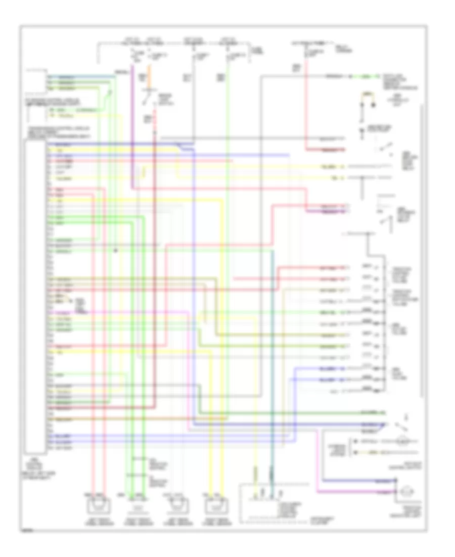
СИСТЕМА АНТИБЛОКИРОВОЧНОЙ ТОРМОЗНОЙ СИСТЕМЫ ABS
Электросхема антиблокировочной тормозной системы АБС (ABS), БУДУЩАЯ для Audi A4 Quattro 1997
Электросхема антиблокировочной тормозной системы АБС (ABS), БУДУЩАЯ для Audi A4 Quattro 1997 - Список элементов:
- (below left side
- Abs
- Abs inlet valves
- Abs outlet valves
- Abs return flow pump
- Abs return flow pump relay
- Abs solenoid valve relay
- All times
- Anti-slip control switch
- Brake lamp switch
- Control
- Data link connector (rear of center console)
- Fuse 25a
- Fuse 13 10a
- Fuse 16 5a
- Fuse 53 50a
- Fuse 7 10a
- Fuse panel
- G200 (left kick panel)
- Hot at
- Hot at all times
- Hot in on or start
- Hydraulic
- Instrument cluster
- Interior lights system
- Left front wheel sensor
- Left rear wheel sensor
- Mfi engine control module (left rear of engine compt)
- Mini check system control module
- Module
- Of rear seat)
- Red
- Relay carrier
- Right front wheel sensor
- Right rear wheel sensor
- T26
- T26a
- Traction control indicator light
- Traction control outlet valves
- Traction control switch-over valves
- Transmission control module (below carpet, forward of passenger's seat)
- Unit
- W/ traction control
- W/o traction control
Электросхема антиблокировочной тормозной системы АБС (ABS), Quattro для Audi A4 Quattro 1997
Электросхема антиблокировочной тормозной системы АБС (ABS), Quattro для Audi A4 Quattro 1997 - Список элементов:
- (below left side
- Abs
- Abs inlet valves
- Abs outlet valves
- Abs return flow pump
- Abs return flow pump relay
- Abs solenoid valve relay
- All times
- Brake lamp switch
- Control
- Data link connector (rear of center console)
- Fuse 13 10a
- Fuse 16 5a
- Fuse 41 25a
- Fuse 53 50a
- Fuse 7 10a
- Fuse panel
- G200 (left kick panel)
- Hot at
- Hot at all times
- Hot in on or start
- Hydraulic
- Instrument cluster
- Left front wheel sensor
- Left rear wheel sensor
- Mini check system control module
- Module
- Of rear seat)
- Red
- Relay carrier
- Right front wheel sensor
- Right rear wheel sensor
- T26a
- Traction control outlet valves
- Traction control switch-over valves
- Unit
СИСТЕМА КОНДИЦИОНЕРА
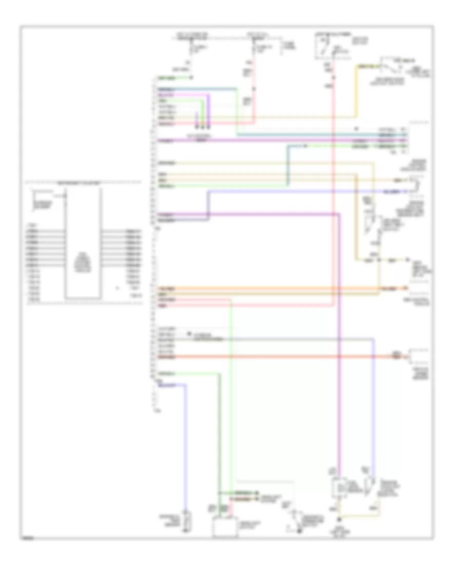
Электросхема кондиционера (1 из 2) для Audi A4 Quattro 1997
Электросхема кондиционера (1 из 2) для Audi A4 Quattro 1997 - Список элементов:
- A/c compressor speed sensor
- A/c control head
- Anti-theft system
- Back pressure flap motor and sensor
- Center outlet temperature sender
- Central flap motor and sensor
- Flap motor and sensor
- Floor outlet temperature sender
- Footwell/defroster
- Fresh air intake duct temperature sensor
- Fuse 10a
- Fuse panel
- G202 (left side of i/p)
- Hot at all times
- Instrument cluster
- Interior lights system
- Interior temperature fan & sensor
- Motronic engine control module
- Outside air temperature sensor
- Sunlight photo sensor
- T26
- T26a
- Temperature regulator flap motor and sensor
- Transmission control module
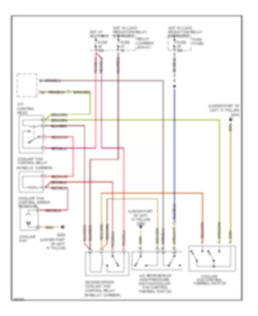
Электросхема кондиционера (2 из 2) для Audi A4 Quattro 1997
Электросхема кондиционера (2 из 2) для Audi A4 Quattro 1997 - Список элементов:
- (in relay carrier)
- (left side of i/p) g202
- (lower part of left "a" pillar) g202
- A/c compressor clutch
- A/c compressor clutch relay (in relay carrier)
- A/c refrigerant
- Coolant fan
- Coolant fan control relay
- Coolant fan control series resistor
- Coolant fan control thermal switch
- Digital outside air temperature/ transmission range selector lever display
- Fan control
- Fresh air blower
- Fuse 10a
- Fuse 30a
- Fuse 40a
- Fuse 5a
- Fuse panel
- G202 (left side of i/p)
- G202 (lower part of left "a" pillar)
- High pressure switch/coolant
- Hot at all times
- Hot in run
- Hot w/ load reduction relay energized
- Relay carrier (8-way)
- Second speed coolant fan control relay
- Thermal switch
СИСТЕМА КРУИЗКОНТРОЛЯ
Электросхема системы круизконтроля для Audi A4 Quattro 1997
Электросхема системы круизконтроля для Audi A4 Quattro 1997 - Список элементов:
- A/t
- Brake light switch
- Cluster
- Clutch vacuum vent valve switch
- Control module
- Cruise control brake pedal switch
- Cruise control module
- Cruise control switch
- Cruise control vacuum pump
- Fuse 10a
- Fuse 15a
- Fuse panel
- G200 (behind left side of i/p)
- Hot at all times
- Hot in on or start
- Instrument
- M/t
- Multi- function transmission range switch
- Speedo- meter
- T26
- Transmission
- Vehicle speed output
- Wire connector (center console)
СИСТЕМА ОХЛАЖДЕНИЯ
Электросхема системы охлаждения для Audi A4 Quattro 1997
Электросхема системы охлаждения для Audi A4 Quattro 1997 - Список элементов:
- (in relay carrier)
- (lower part of left "a" pillar)
- (lower part of left "a" pillar) g202
- A/c control head
- A/c refrigerant
- Coolant fan
- Coolant fan control relay
- Coolant fan control series resistor
- Coolant fan control thermal switch
- Fan control
- Fuse 30a
- Fuse 40a
- Fuse 5a
- Fuse panel
- G202
- High pressure switch/coolant
- Hot at all times
- Hot w/ load reduction relay energized
- Relay carrier (8-way)
- Second speed coolant fan control relay
- Thermal switch
СИСТЕМА ПЕРЕДАЧИ ДАННЫХ
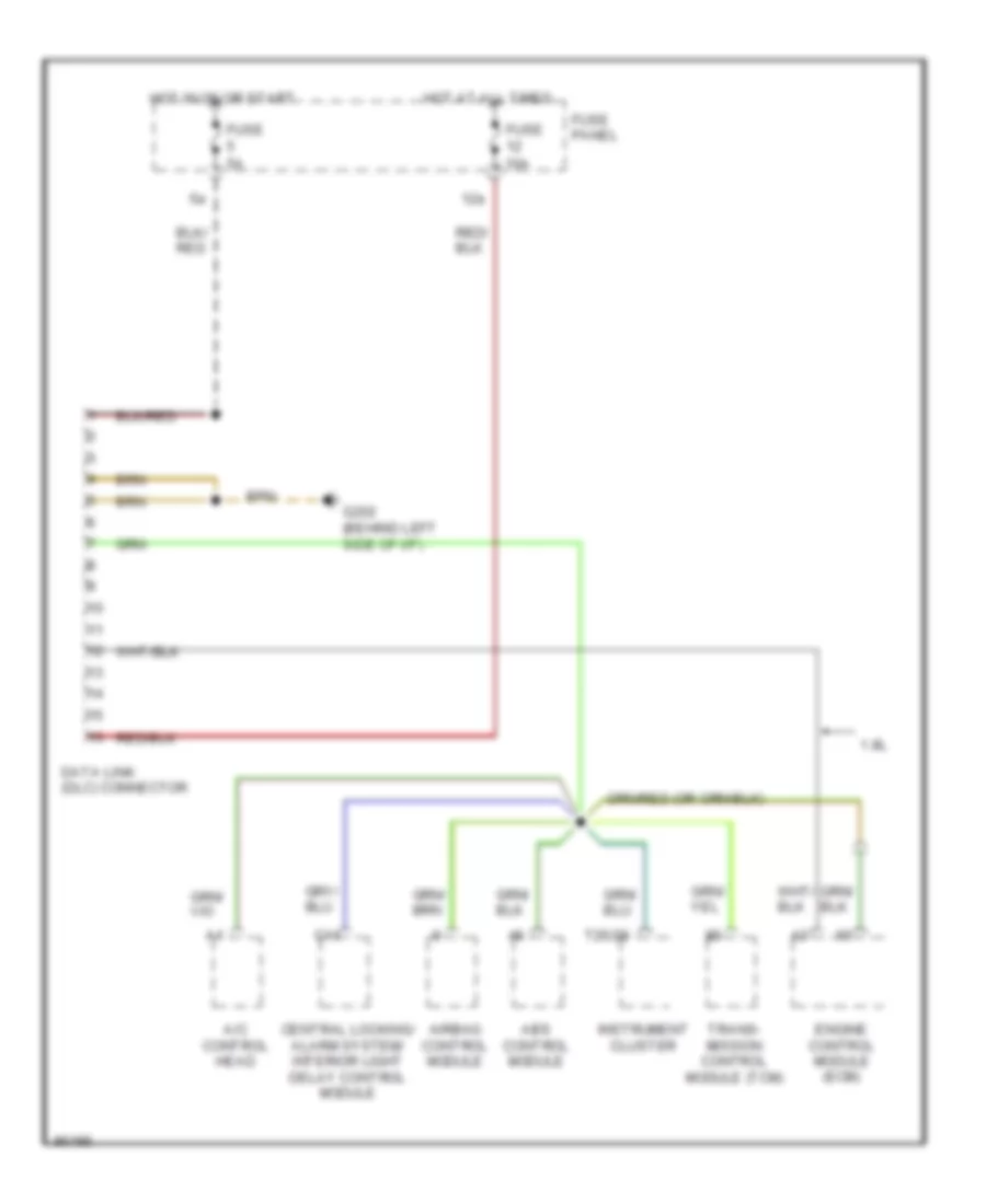
Электросхема линии передачи данных CAN для Audi A4 Quattro 1997
Электросхема линии передачи данных CAN для Audi A4 Quattro 1997 - Список элементов:
- 1.8l
- 12a
- A/c control head
- Abs control module
- Airbag control module
- C14
- Central locking/ alarm system/ interior light delay control module
- Data link (dlc) connector
- Engine control module (ecm)
- Fuse 10a
- Fuse 5a
- Fuse panel
- G202 (behind left side of i/p)
- Hot at all times
- Hot in on or start
- Instrument cluster
- T26/20
- Trans- mission control module (tcm)
СИСТЕМА УПРАВЛЕНИЯ ДВИГАТЕЛЯ
1.8L
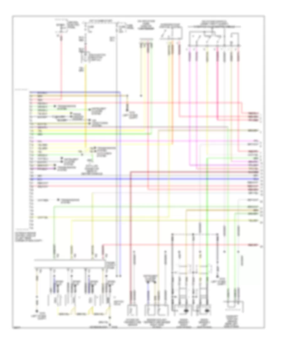
1.8L, Электросхема системы управления двигателем (1 из 2) для Audi A4 Quattro 1997
1.8L, Электросхема системы управления двигателем (1 из 2) для Audi A4 Quattro 1997 - Список элементов:
- (left of eng compt)
- (on air intake hose) mass air flow sensor
- (on eng block)
- (on intake manifold, under throttle body) throttle valve control module
- Air conditioning system
- Bat(30)
- Camshaft position sensor (rear left side of eng)
- Central electric panel
- Data link connector (rear of center console)
- Diagnosis pump (for fuel system)
- Engine coolant temperature sensor (right side of eng)
- Fuse 10a
- Fuse 20a
- Fuse panel
- G100
- G132
- Hot in on or start
- Ignition coils
- Iii
- Instrument cluster system
- Intake air temperature sensor
- Knock sensor 1 (right side of eng)
- Knock sensor 2 (left side of eng)
- Malfunction indicator lamp (mil)
- Motronic engine control module (in left rear corner of eng compt)
- Nca
- Power output stage
- Red
- Spark plug
- T4f
- T5c
- Trans- missions system
- Transmissions system
- Transmissions system auto check system
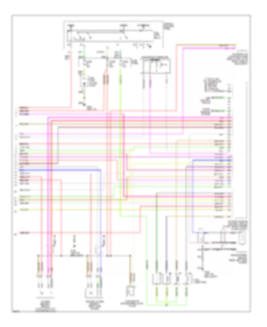
1.8L, Электросхема системы управления двигателем (2 из 2) для Audi A4 Quattro 1997
1.8L, Электросхема системы управления двигателем (2 из 2) для Audi A4 Quattro 1997 - Список элементов:
- 87f
- 87f/dti
- 87a
- Abs control module
- Barometric pressure sensor
- Bat(30)
- Central electric panel
- Data link connector (rear of center console)
- Engine speed sensor (rear left side of eng)
- Evaporative canister purge regulator valve (right side of eng compt)
- Fuel injectors
- Fuel pump (in fuel tank)
- Fuel pump relay
- Fuse 10a
- Fuse 15a
- Fuse 20a
- Fuse panel
- G100 (left of eng compt)
- G202 (left i/p)
- Heated oxygen sensor 1 (right side of eng)
- Ign(15)
- Motronic engine control module (in left rear corner of eng compt)
- Nca
- Oxygen sensor 1 (behind 3 way catalytic converter (twc))
- Red
- Start(50a)
- Trans- missions system
- Wastegate bypass regulator valve
2.8L
2.8L, Электросхема системы управления двигателем (1 из 2) для Audi A4 Quattro 1997
2.8L, Электросхема системы управления двигателем (1 из 2) для Audi A4 Quattro 1997 - Список элементов:
- (left of eng compt)
- (on air intake hose) mass air flow sensor
- (on intake manifold, under throttle body) throttle valve control module
- Air conditioning system
- Antilock brakes system
- Auto check system
- Bat(30)
- Camshaft position sensor 1 (rear left side of eng)
- Camshaft position sensor 2 (rear left side of eng)
- Central electric panel
- Data link connector (rear of center console)
- Diagnosis pump (for fuel system)
- Engine coolant temperature sensor (right side of eng)
- Fuse 20a
- Fuse 5a
- Fuse panel
- G100
- Hot in on or start
- Ignition coil 1
- Ignition coil 2
- Ignition coil 3
- Ignition coils
- Instrument cluster system
- Knock sensor 1 (right side of eng)
- Knock sensor 2 (left side of eng)
- Malfunction indicator lamp (mil)
- Motronic engine control module (in left rear corner of eng compt)
- Nca
- Power output stage
- Red
- Solid state
- Spark plugs 1 & 6
- Spark plugs 2 & 4
- Spark plugs 3 & 5
- Temperature sensor ii
- Trans- missions system
- Transmissions system
2.8L, Электросхема системы управления двигателем (2 из 2) для Audi A4 Quattro 1997
2.8L, Электросхема системы управления двигателем (2 из 2) для Audi A4 Quattro 1997 - Список элементов:
- (left of eng compt)
- 13-way relay carrier
- 3-way relay carrier
- 87f
- 87f/dti
- 87a
- Abs control module
- Bat(30)
- Camshaft adjusment valve 1
- Camshaft adjusment valve 2
- Central electric panel
- Engine speed sensor (rear left side of eng)
- Evaporative canister purge regulator valve (right side of eng compt)
- Fuel injectors
- Fuel pump (in fuel tank)
- Fuel pump relay
- Fuse 15a
- Fuse 20a
- Fuse 50a
- Fuse panel
- G100
- G202 (left i/p)
- Heated oxygen sensor 1 (right side of eng)
- Heated oxygen sensor 2 (left side of eng)
- Hot in on or start
- Ign(15)
- Intake manifold changeover valve
- Motronic engine control module (in left rear corner of eng compt)
- Nca
- Oxygen sensor 1 (behind 3 way catalytic converter (twc))
- Oxygen sensor 2 (behind 3 way catalytic converter (twc))
- Red
- Secondary air injection (air) relay
- Secondary air injection pump motor
- Secondary air injection solenoid valve
- Start(50a)
- Trans- missions system
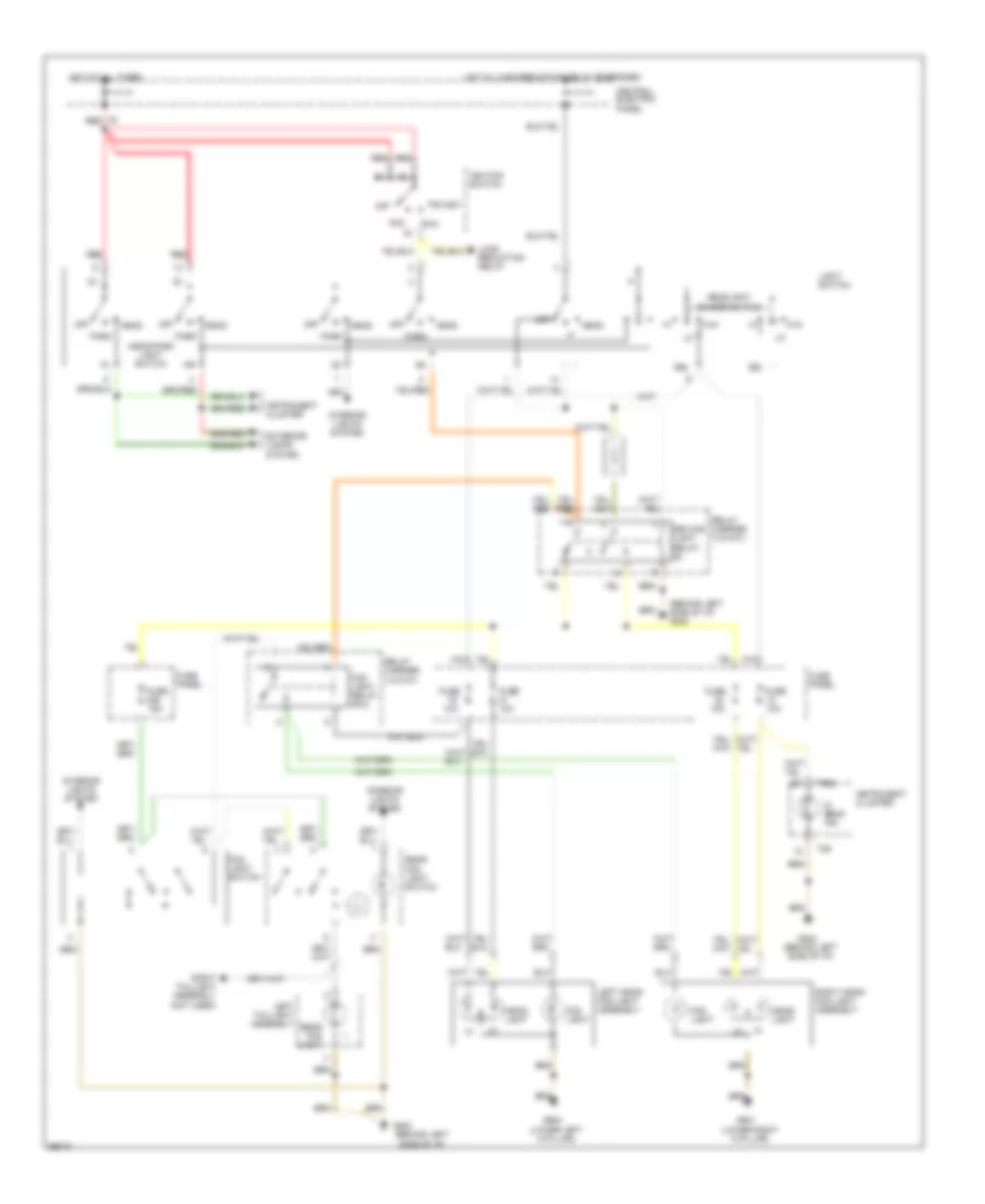
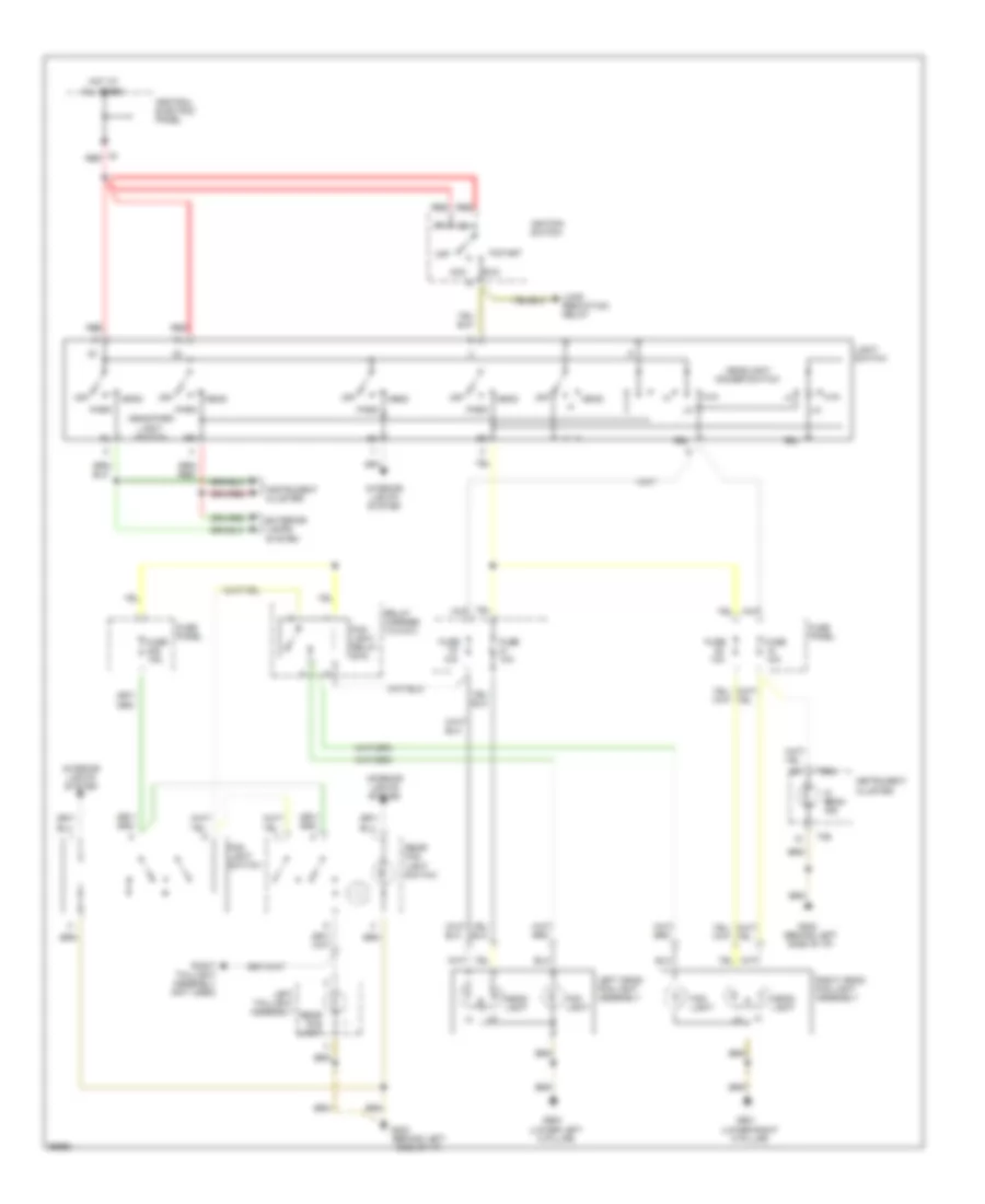
Система Фар
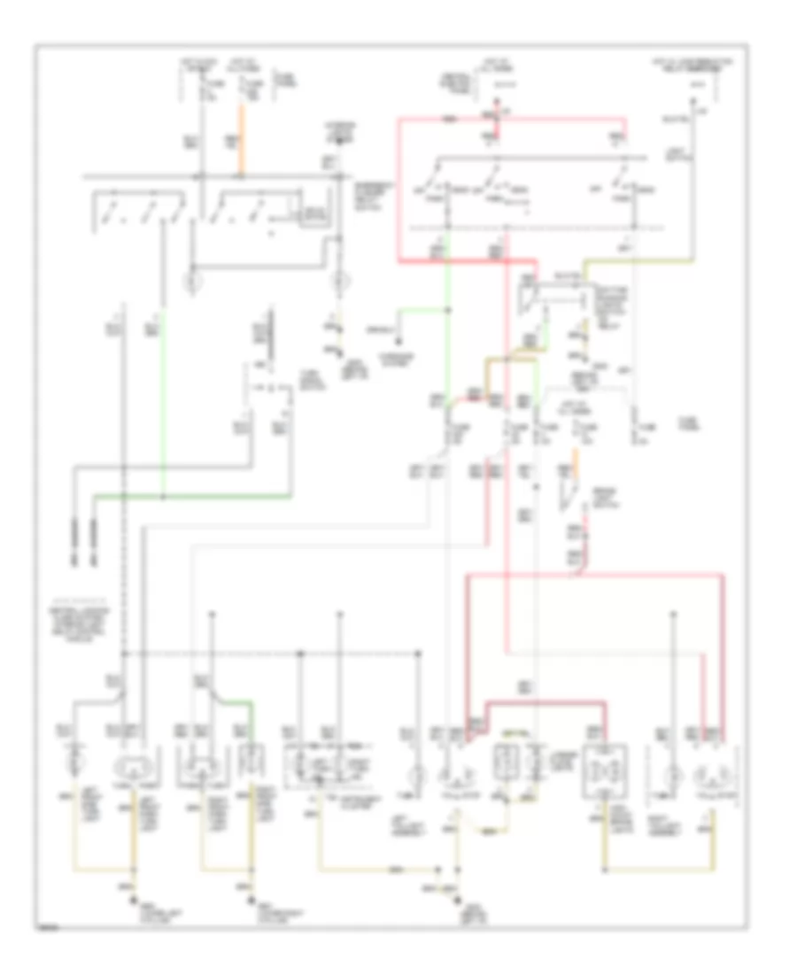
Электросхема фар и противотуманок, С DRL для Audi A4 Quattro 1997
Электросхема фар и противотуманок, С DRL для Audi A4 Quattro 1997 - Список элементов:
- (behind left side of i/p)
- (behind left side of i/p) g202
- (lower left a pillar)
- (lower right a pillar)
- 10a
- 56a
- 56b
- Acc
- Central electric panel
- Driving light relay (9)
- Exterior lamps
- Fog light
- Fog light relay (#10)
- Fog light switch
- Ftp
- Fuse
- Fuse 10a
- Fuse 15a
- Fuse panel
- G202
- G900
- G901
- Head
- Head- light
- Head/park light switch
- Headlight dimmer switch
- Hi beam ind.
- Hot at all times
- Hot w/ load reduction relay energized
- Ignition switch
- Instrument cluster
- Interior lights system
- Left head/ fog light assembly
- Left taillight assembly
- Light switch
- Load reduction relay
- Off
- Park
- Rear fog light
- Rear fog light switch
- Red
- Relay carrier (13-way)
- Right head/ fog light assembly
- Right taillight assembly (not used)
- Run
- Start
- System
- T26
- T26a
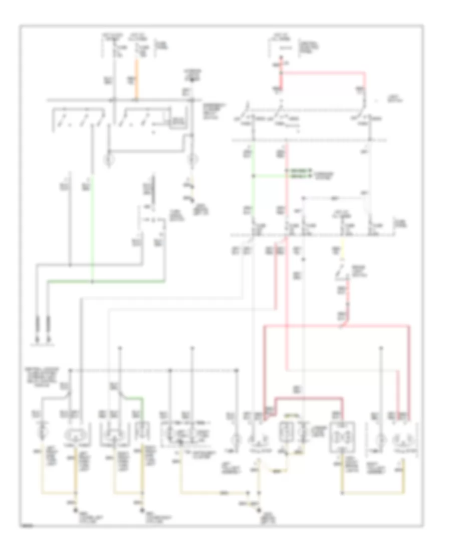
Электросхема фар и противотуманок, без DRL для Audi A4 Quattro 1997
Электросхема фар и противотуманок, без DRL для Audi A4 Quattro 1997 - Список элементов:
- (behind left side of i/p)
- (lower left a pillar)
- (lower right a pillar)
- 10a
- 56a
- 56b
- Acc
- All times
- Central electric panel
- Exterior lamps
- Fog light
- Fog light relay (#10)
- Fog light switch
- Ftp
- Fuse
- Fuse 10a
- Fuse 15a
- Fuse panel
- G202
- G900
- G901
- Head
- Head- light
- Head/park light switch
- Headlight dimmer switch
- Hi beam ind.
- Hot at
- Ignition switch
- Instrument cluster
- Interior lights system
- Left head/ fog light assembly
- Left taillight assembly
- Light switch
- Load reduction relay
- Off
- Park
- Rear fog light
- Rear fog light switch
- Red
- Relay carrier (13-way)
- Right head/ fog light assembly
- Right taillight assembly (not used)
- Run
- Start
- System
- T26
- T26a
СИСТЕМЫ СИДЕНИЙ
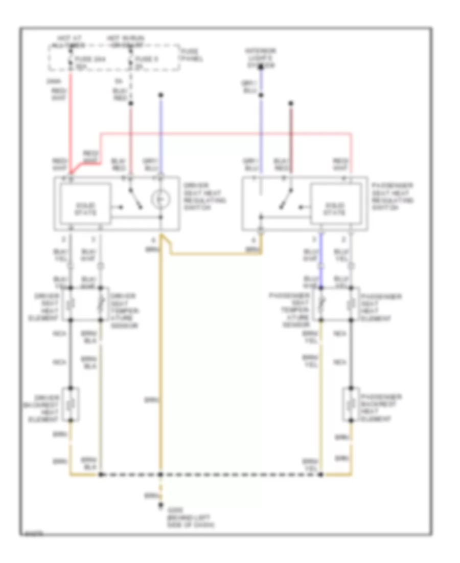
Электросхема подогрева сидений для Audi A4 Quattro 1997
Электросхема подогрева сидений для Audi A4 Quattro 1997 - Список элементов:
- 244a
- All times
- Driver backrest heat element
- Driver seat heat element
- Driver seat heat regulating switch
- Driver seat temper- ature sensor
- Fuse 244 30a
- Fuse 5 5a
- Fuse panel
- G202 (behind left side of dash)
- Hot at
- Hot in run or start
- Interior lights system
- Nca
- Passenger backrest heat element
- Passenger seat heat element
- Passenger seat heat regulating switch
- Passenger seat temper- ature sensor
- Solid state
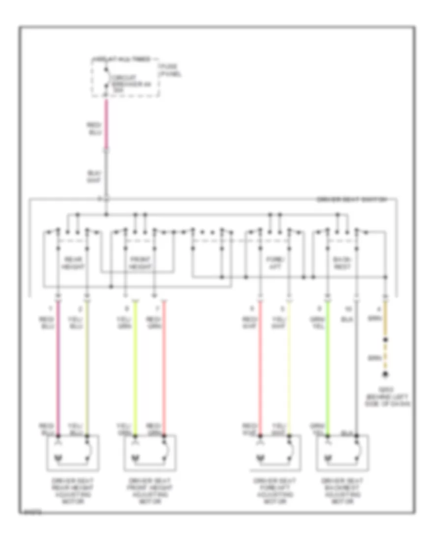
Электросхема привода сидений левой стороны для Audi A4 Quattro 1997
Электросхема привода сидений левой стороны для Audi A4 Quattro 1997 - Список элементов:
- Back- rest
- Circuit breaker 44 30a
- Driver seat backrest adjusting motor
- Driver seat fore/aft adjusting motor
- Driver seat front height adjusting motor
- Driver seat rear height adjusting motor
- Driver seat switch
- Fore/ aft
- Front height
- Fuse panel
- G202 (behind left side of dash)
- Hot at all times
- Rear height
Стартер Генератор
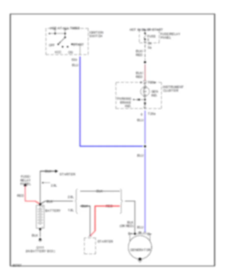
Электросхема Генератора для Audi A4 Quattro 1997
Электросхема Генератора для Audi A4 Quattro 1997 - Список элементов:
- 1.8l
- 2.8l
- 50b
- Acc
- Battery
- Fuse 5a
- Fuse/ relay panel
- Fuse/relay panel
- G111 (in battery box)
- Gen ind.
- Generator
- Hot at all times
- Hot in on or start
- Ignition switch
- Instrument cluster
- Off
- Parking brake ind.
- Red
- Start
- Starter
- T26a
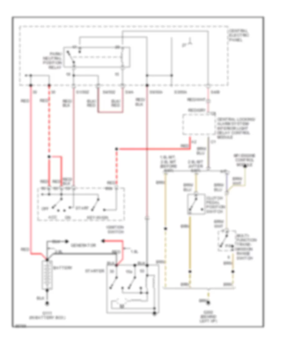
Электросхема стартера для Audi A4 Quattro 1997
Электросхема стартера для Audi A4 Quattro 1997 - Список элементов:
- 1.8l
- 1.8l m/t, 2.8l m/t (before 5/97)
- 15a
- 2.8l
- 2.8l m/t (after 5/97)
- 86a
- A/t
- Acc
- Battery
- Central electric panel
- Central locking/ alarm system/ interior light delay control module
- Clutch pedal position switch
- G111 (in battery box)
- G202 (behind left i/p)
- Generator
- Ignition switch
- Key-in ign
- Mfi engine control module
- Multi- function trans- mission range switch
- Off
- P/n
- Park/ neutral position relay
- Red
- S1/50z
- S3/50a
- S4/50z
- S4/a
- S4/b
- S6/50a
- Start
- Starter
Стеклоочистители и Стеклоомыватели Дворники
Электросхема стеклоочистителя, дворников и омывателя для Audi A4 Quattro 1997
Электросхема стеклоочистителя, дворников и омывателя для Audi A4 Quattro 1997 - Список элементов:
- 58a
- 75a
- Brake fluid level warning switch
- Central electric panel
- Fuse 1 5a
- Fuse 24 25a
- Fuse panel
- G202 (behind left side of i/p)
- G900 (lower left a pillar)
- Headlight washer pump
- Headlight washer system relay
- Hot at all times
- Hot in on or acc
- Hot w/ park or headlights on
- Instrument cluster system
- Left washer nozzle heater (optional)
- Nca
- Red
- Right washer nozzle heater (optional)
- S1/31
- S2/31b
- S2/53c
- S2/53e
- S2/j
- S5/p
- Solid state
- Washer fluid level switch
- Washer switch
- Windshield washer pump
- Windshield wiper intermittent switch
- Windshield wiper motor
- Wiper switch
- Wiper/ washer inter- mittent relay
ЦЕНТРАЛЬНЫЙ ЗАМОК
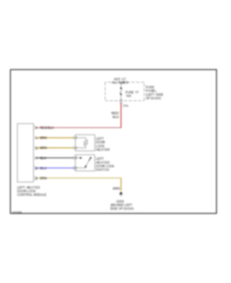
горячая дверь захватывает схему для Audi A4 Quattro 1997
горячая дверь захватывает схему для Audi A4 Quattro 1997 - Список элементов:
- 17a
- All times
- Fuse 17 10a
- Fuse panel (left side of dash)
- G202 (behind left side of dash)
- Hot at
- Left door lock heater
- Left heated door lock control module
- Left heated door lock switch

 Čeština
 Dansk
Dansk Deutsch
 Ελληνικά
 English
 English
 Español
 Suomi
Suomi Français
 Français
 עברית
עברית Hrvatski
 Magyar
 Italiano
 日本語
日本語 한국어
한국어 Polski
 Português
 Português
 Română
 Русский
 Slovenčina
 Slovenščina
 Svenska
 Türkçe
 中文 (中国)