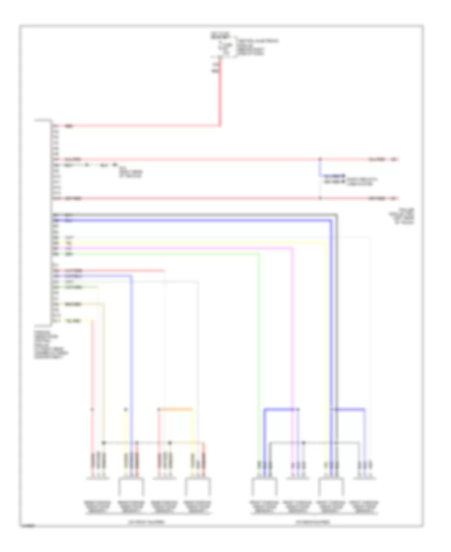
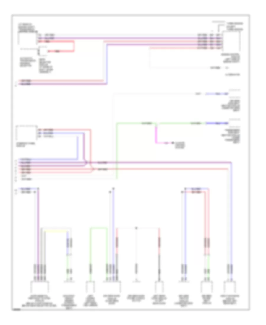
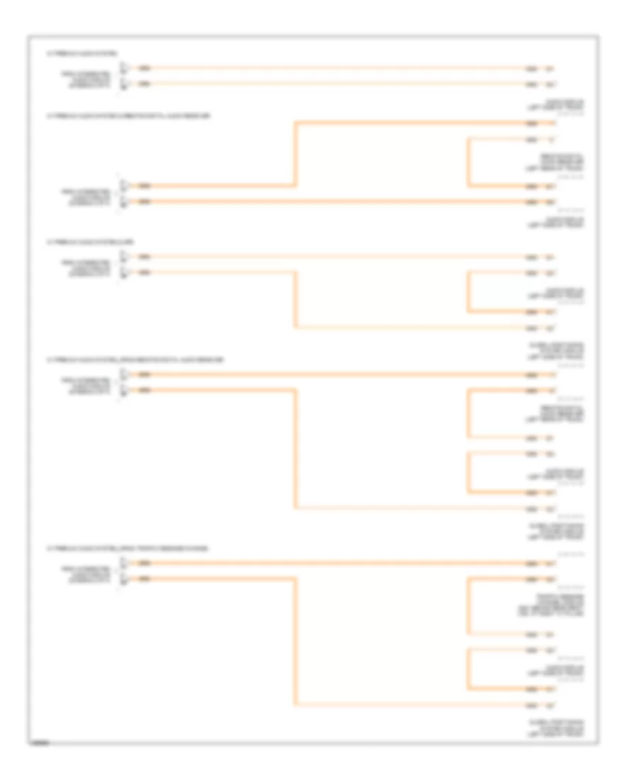
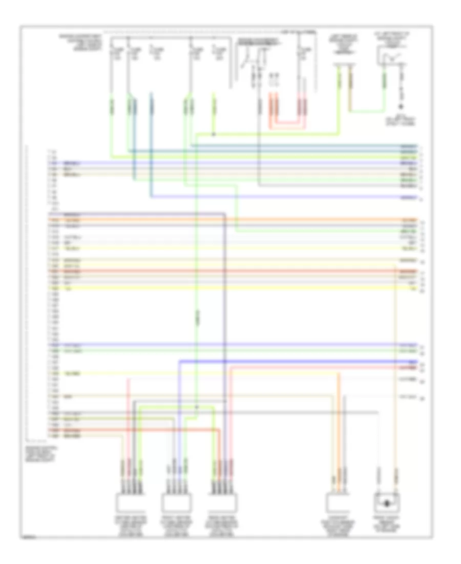
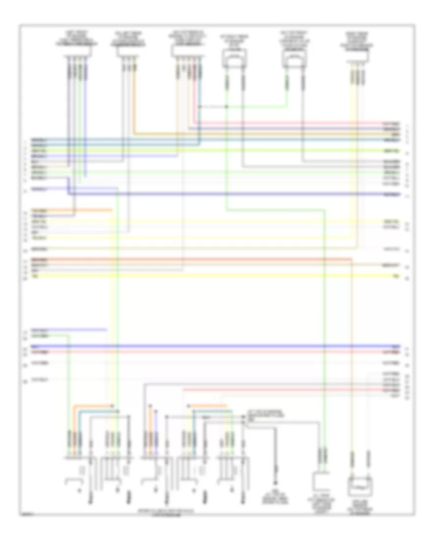
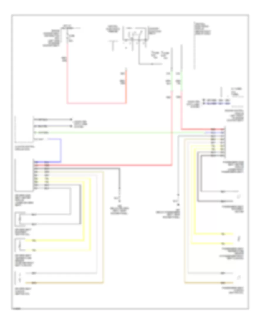
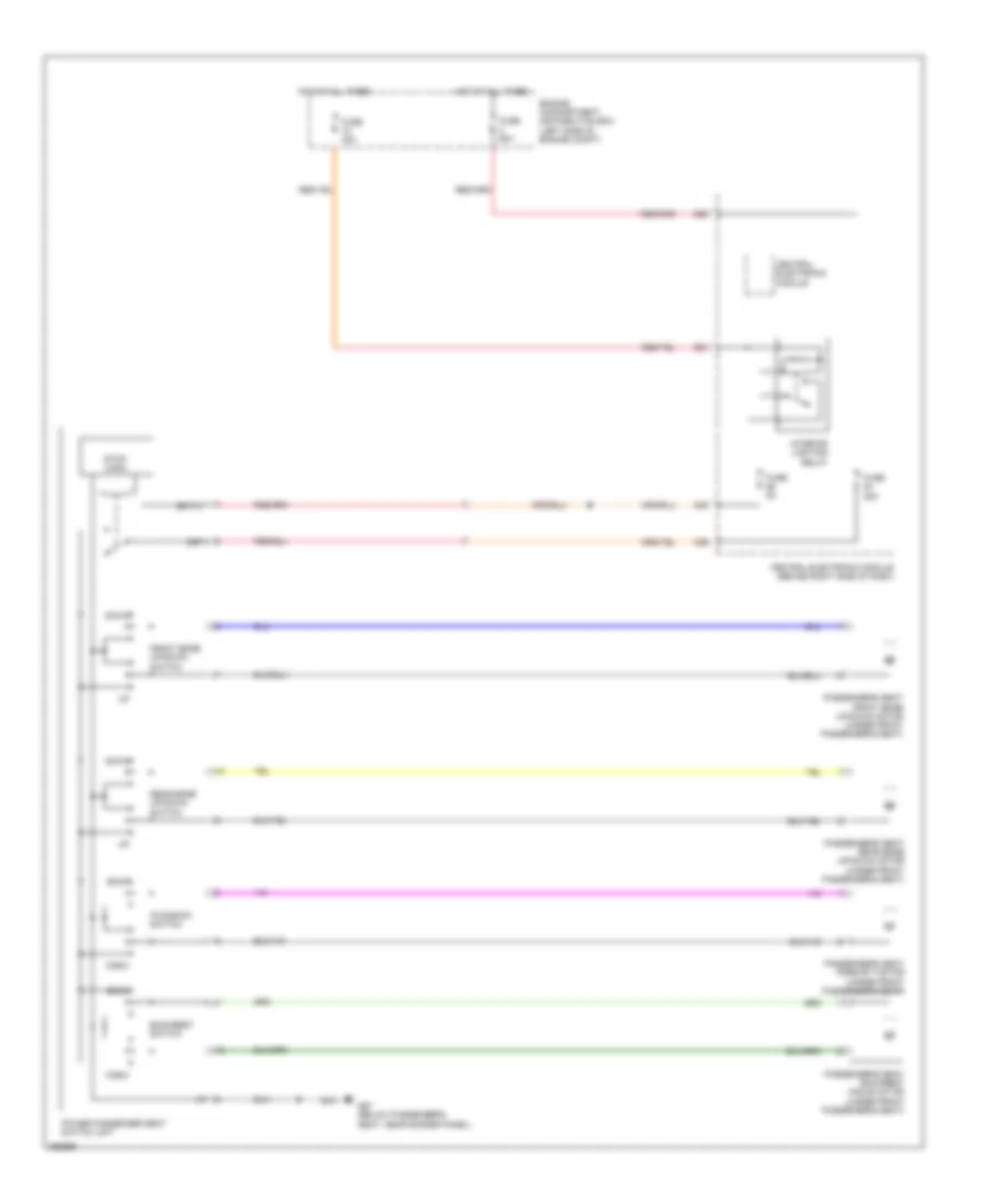
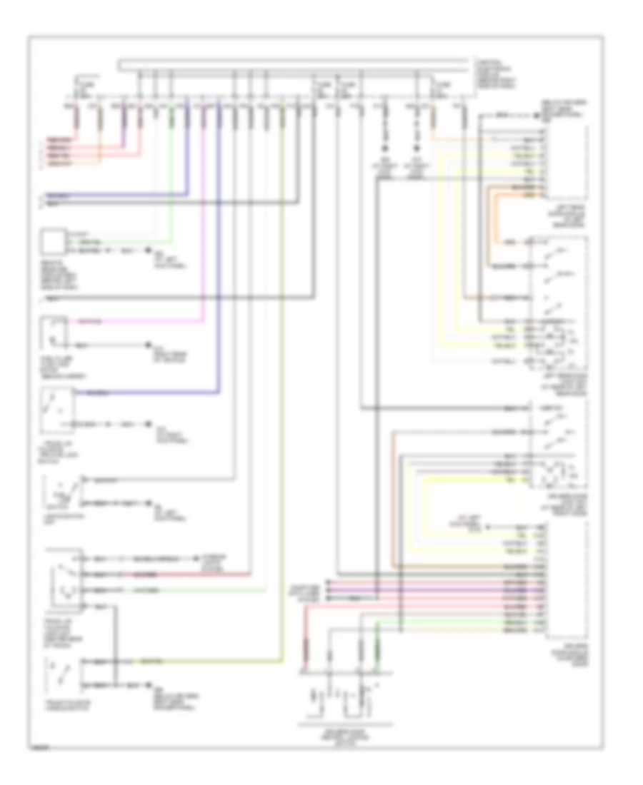
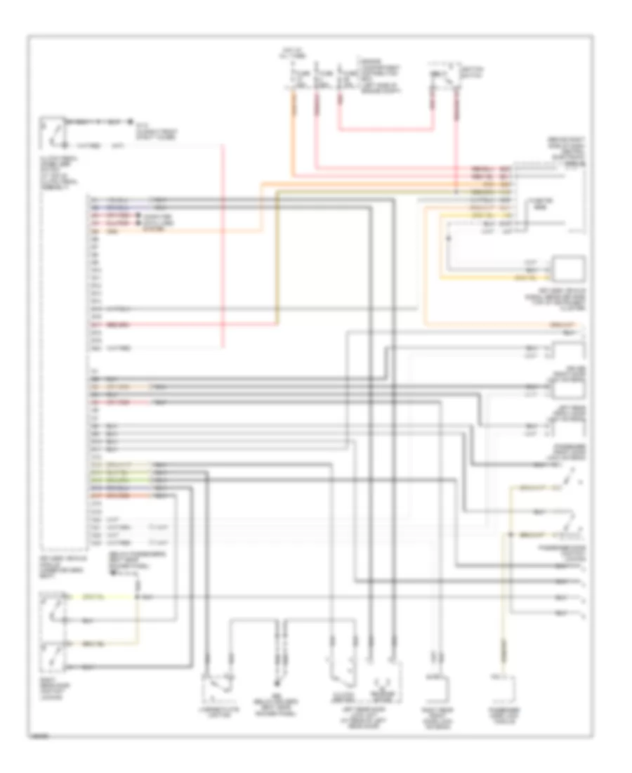
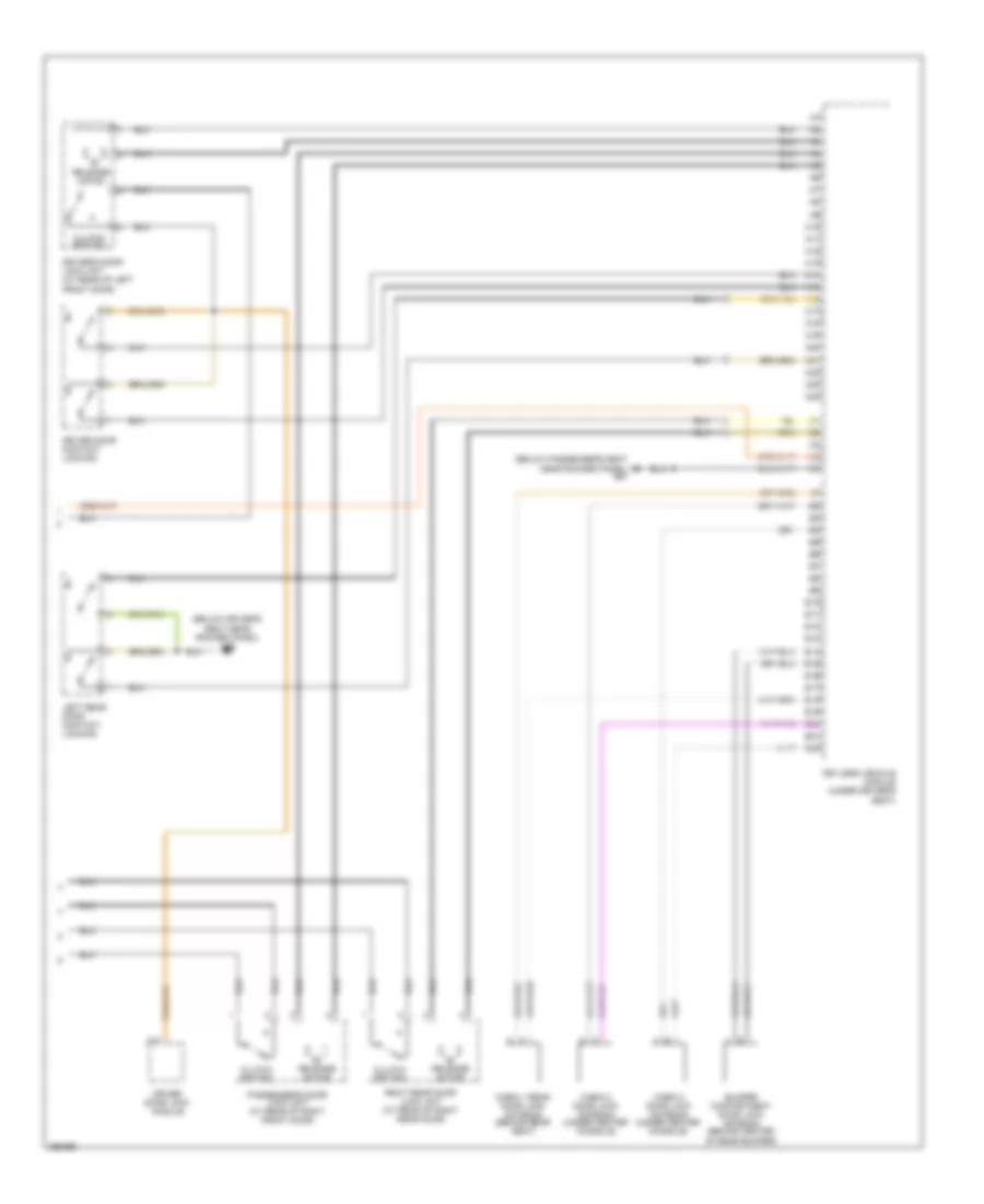
Автомтическая коробка Передач (АКПП) Полная привод (4WD) Блокировка Дифференциала
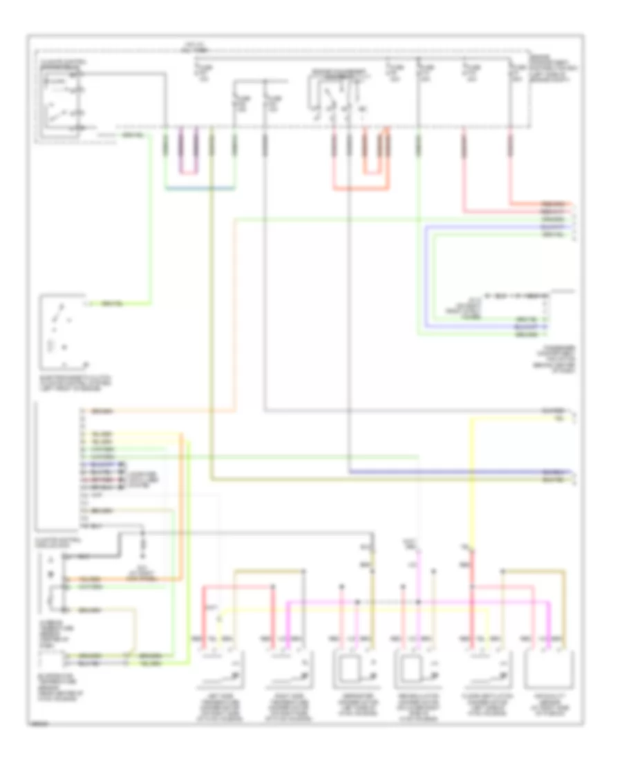
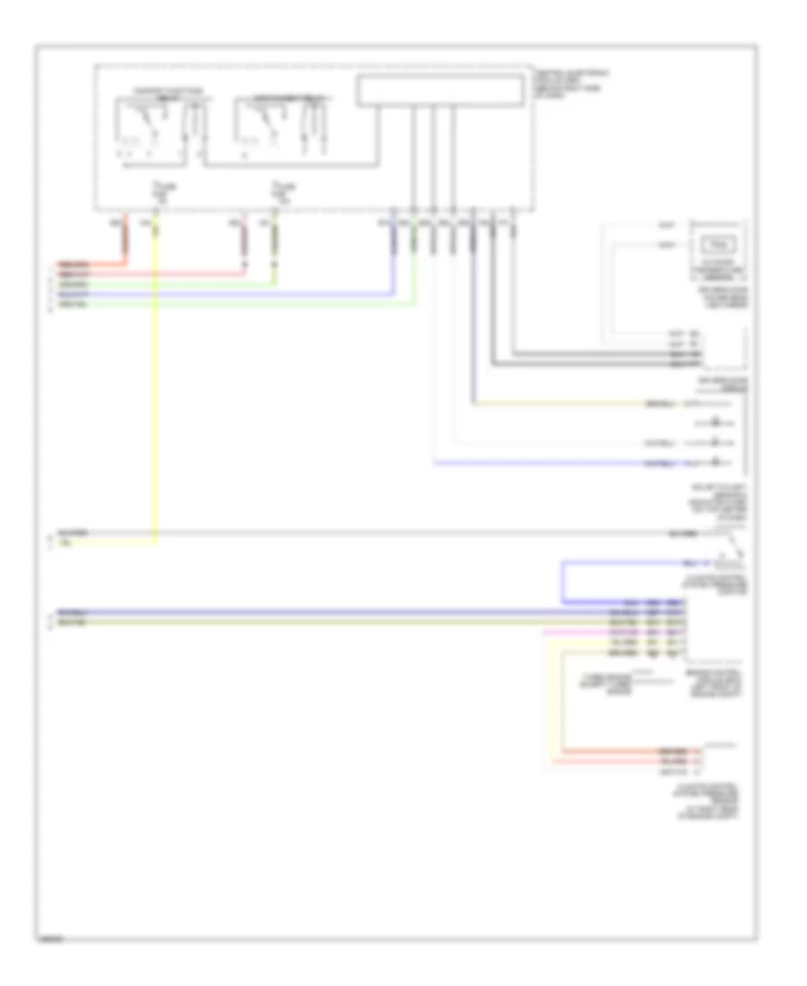
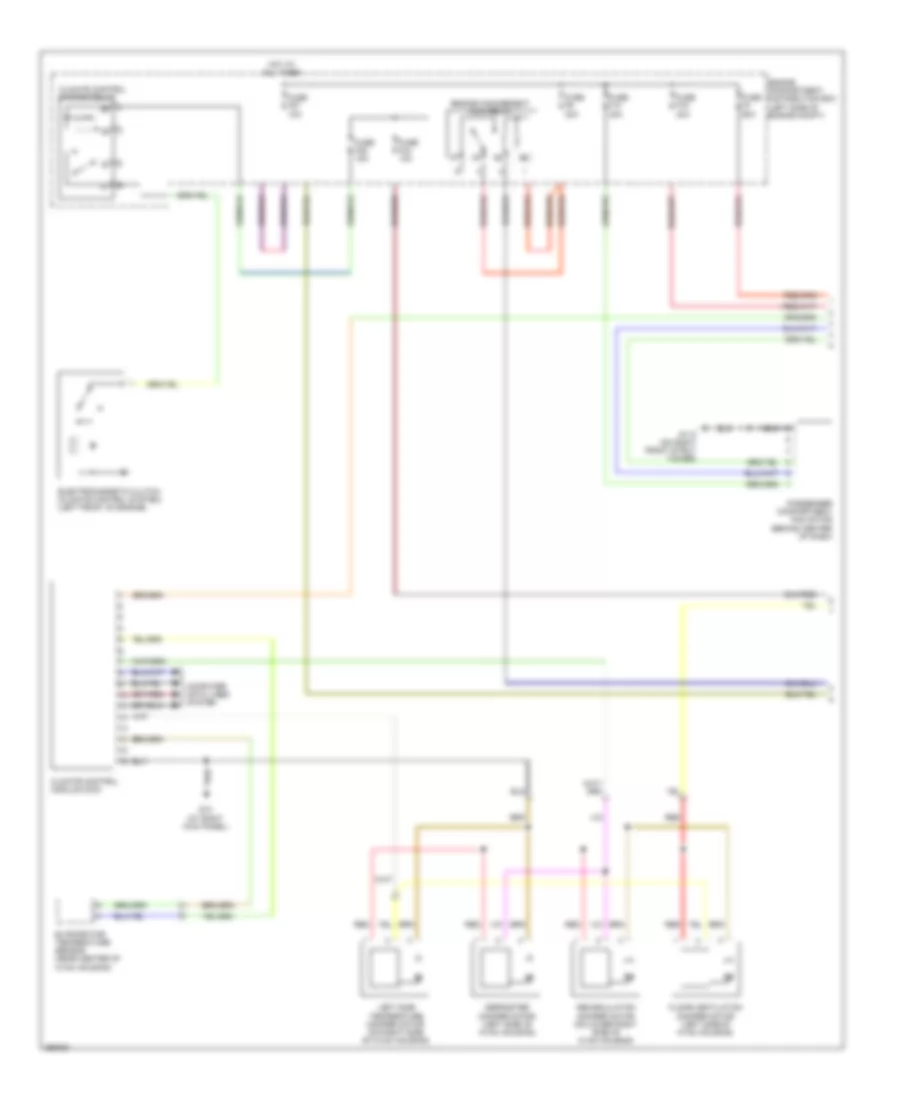
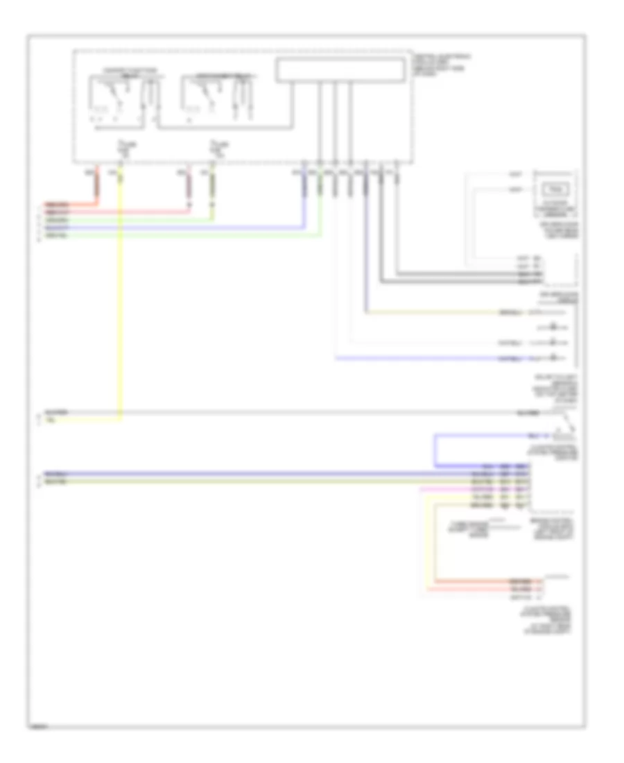
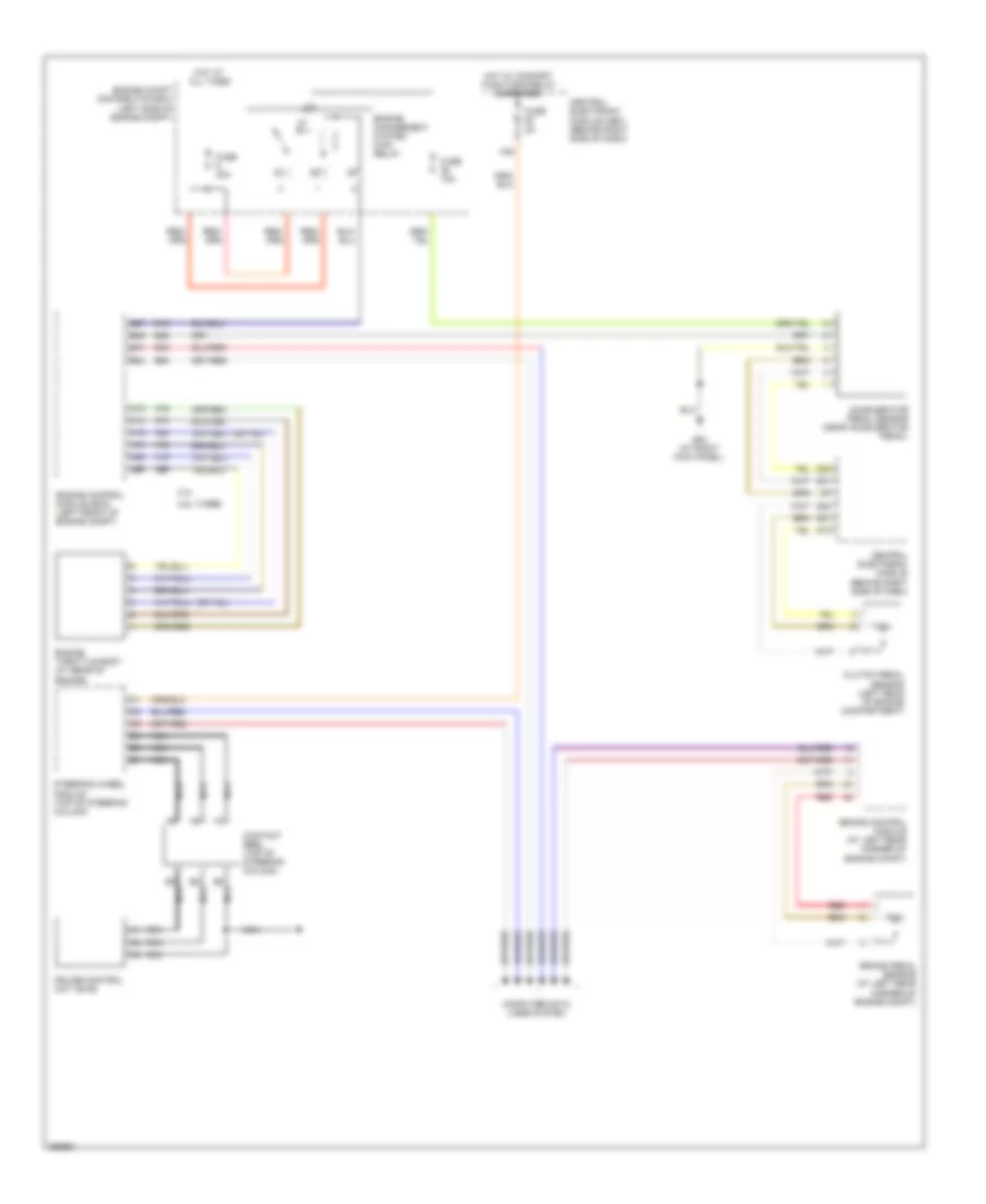
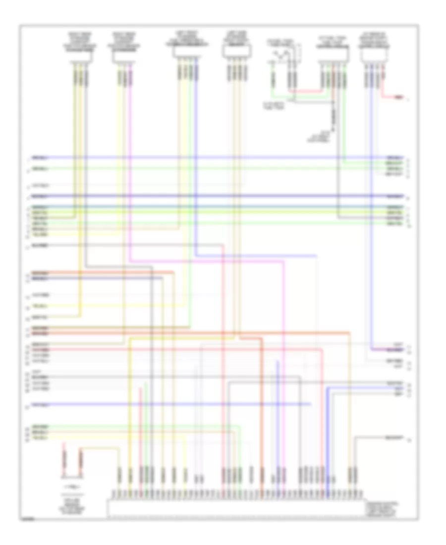
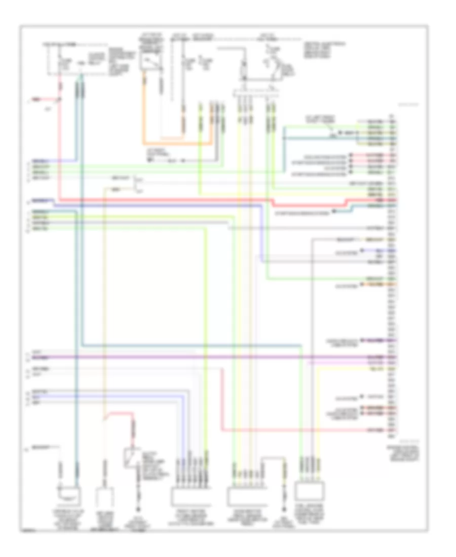
Электросхема коробки передач АКПП для Volvo V50 2007
 https://portal-diagnostov.com/license.html
Automotive Electricians Portal FZCO
Automotive Electricians Portal FZCO
https://portal-diagnostov.com/license.html
https://portal-diagnostov.com/license.html
Automotive Electricians Portal FZCO
Automotive Electricians Portal FZCO
Электросхема коробки передач АКПП для Volvo V50 2007 - Список элементов:
- A10
- A11
- A12
- A13
- A14
- A15
- A16
- Automatic transmission (under transmission cover)
- Automatic transmission program selector
- B13
- B15
- B16
- B44
- B54
- B57
- Brake control module (bcm) (at left rear corner of engine compt)
- C10
- C11
- C12
- C13
- C14
- C15
- C16
- C17
- C18
- C19
- C20
- C21
- C22
- Central electronic module (behind right side of dash)
- Computer data lines system
- Engine compartment distribution box (left side of engine compt)
- Engine control module (ecm) (left front of engine compt)
- Except turbo engine
- Fuse f23 10a
- Fuse f52 5a
- G14
- G15
- G52 (at left front strut tower)
- Gear selector module
- Hot at all times
- Hot in on or start
- Input speed sensor (on rear of transaxle)
- Oil temperature sensor
- Otg
- Output speed sensor (on top of transaxle)
- Red
- Shift solenoid 1
- Shift solenoid 3
- Shift solenoid 4
- Shift solenoid 5
- Sls
- Slsg
- Slt
- Sltg
- Slu
- Slug
- Solenoid 2 shift
- Solenoid lock-up
- Solenoid pressure
- Solenoid throttle
- Sp1+
- Sp1-
- Sp2+
- Sp2-
- Transmission control module (tcm) (at rear of engine compt)
- Turbo engine
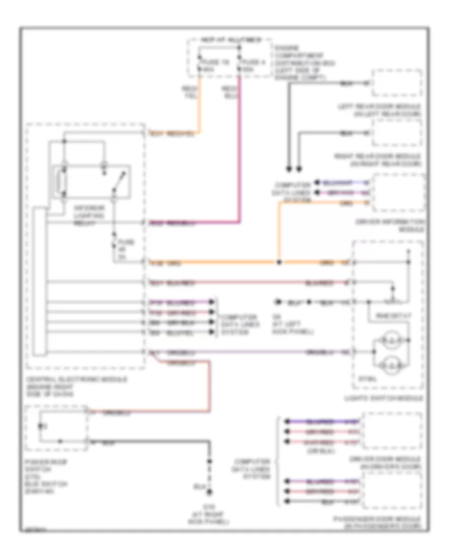
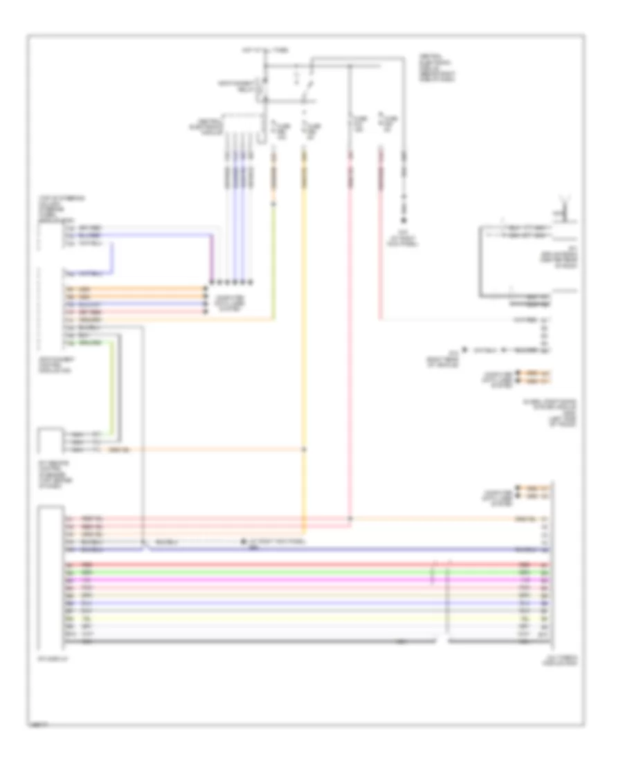
БАГАЖНИК ЗАДНЯЯ ДВЕРЬ ЛЮЧОК ТОПЛИВНОГО БАКА
Электросхема открывания багажника и лючка топливного бака для Volvo V50 2007
Электросхема открывания багажника и лючка топливного бака для Volvo V50 2007 - Список элементов:
- Central electronic module (behind right side of dash)
- Engine compartment distribution box (left side of engine compt)
- Fuel
- Fuel filler flap lock motor (right side of cargo compt, behind carpet)
- Fuse 40a
- Fuse 60a
- G10 (at right kick panel)
- G12 (right rear of vehicle)
- G6 (at left kick panel)
- G66 (below driver's seat, near rocker panel)
- G83 (at left kick panel)
- G84 (at right kick panel)
- Hot at all times
- Interior lights system
- Lid
- Lights switch module
- Private lock
- Remote keyless receiver (behind left side of dash)
- Switch
- Tailgate
- Trunk lid/
- Trunk lid/tailgate handle switch
- Trunk lid/tailgate lock unit
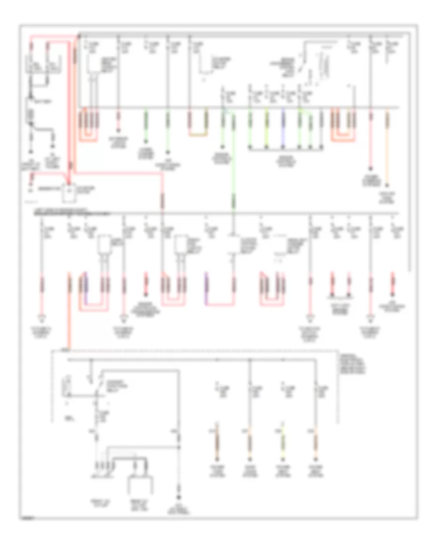
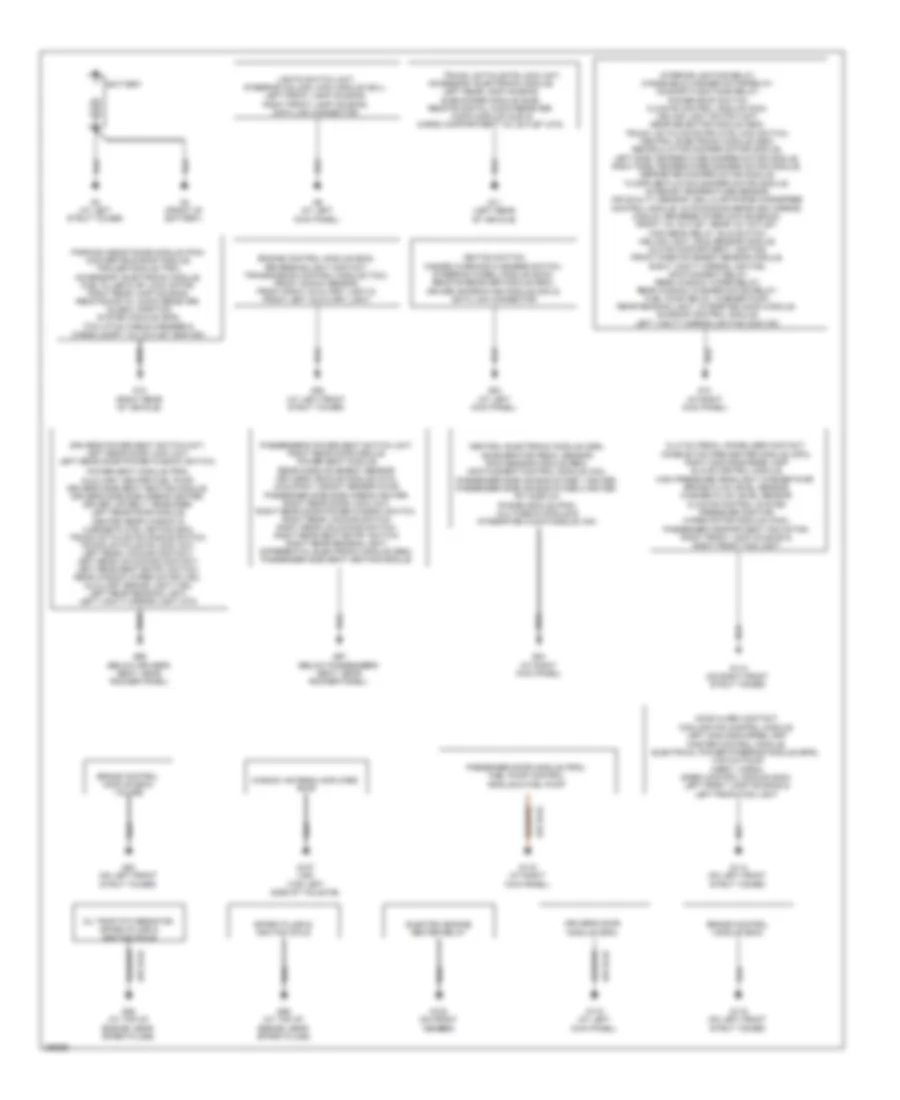
БЛОК ПРЕДОХРАНИТЕЛЕЙ И РЕЛЕ
Электросхема блока предохранителей и реле (1 из 2) для Volvo V50 2007
Электросхема блока предохранителей и реле (1 из 2) для Volvo V50 2007 - Список элементов:
- (left side of engine compt) engine compartment distribution box
- A23
- A28
- Air conditioning system
- Anti-lock brakes system
- Battery
- C27
- C29
- C30
- Cem
- Central electronic module (cem) (behind right side of dash)
- Climate control system relay
- Comfort functions relay
- Cooling fans system
- D14
- Door locks system
- E20
- Engine controls & transmissions systems
- Engine controls system
- Engine management system main relay
- Exterior lights system
- Front 12v outlet
- Front fog lights relay
- Fuse 10a
- Fuse 15a
- Fuse 20a
- Fuse f1 50a
- Fuse f10 40a
- Fuse f11 20a
- Fuse f12 30a
- Fuse f13 30a
- Fuse f14 40a
- Fuse f16 40a
- Fuse f17 30a
- Fuse f18 40a
- Fuse f2 80a
- Fuse f20 15a
- Fuse f21 20a
- Fuse f23 10a
- Fuse f26 15a
- Fuse f27 10a
- Fuse f29 15a
- Fuse f3 60a
- Fuse f4 60a
- Fuse f45 15a
- Fuse f62 20a
- Fuse f63 20a
- Fuse f7 30a
- Fuse f8 20a
- Fuse f84 25a
- Fuse f85 25a
- Fuse f9 30a
- G10 (at right kick panel)
- G3 (at left strut tower)
- G4 (front of battery)
- Generator
- Headlight washer motor relay
- Heated rear window relay
- Horn relay
- Nca
- Pf1 150a
- Pf2 150a
- Power seat system
- Power steering systems
- Power tops system
- Rear 12v outlet (s40, v50)
- Red
- Starter motor
- Starter motor relay
- To fuse 54 (diagram 2 of 2)
- To fuse 57 (diagram 2 of 2)
- To fuse 74 (diagram 2 of 2)
- To ignition switch (diagram 2 of 2)
- Wiper/ washer system
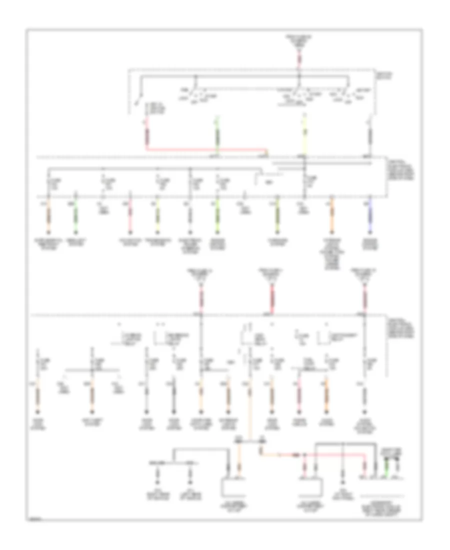
Электросхема блока предохранителей и реле (2 из 2) для Volvo V50 2007
Электросхема блока предохранителей и реле (2 из 2) для Volvo V50 2007 - Список элементов:
- (not used)
- 12v cargo compartment outlet
- A10
- A15
- A16
- A17
- A18 (not used)
- A30
- A42
- Acc
- Accessory electronic module (right rear corner of cargo compt)
- Anti-theft system
- Audio system
- Audio system, navigation system
- C18
- C21
- C22
- C24
- C25 (not used)
- C31
- C38
- C39
- C41
- C44
- C70
- Cem
- Central electronic module (cem) (behind right side of dash)
- Computer data lines system
- Door lock system
- E21
- E22
- E23
- E28
- E29
- E36
- Electronic power steering system
- Engine control system
- Exterior lights system
- From fuse 16 (diagram 1 of 2)
- From fuse 18 (diagram 1 of 2)
- From fuse 26 (diagram 1 of 2)
- From fuse 4 (diagram 1 of 2)
- Fuel pump relay
- Fuse 15a
- Fuse f43 15a
- Fuse f44 10a
- Fuse f51 10a
- Fuse f52 5a
- Fuse f53 10a
- Fuse f54 10a
- Fuse f55 20a
- Fuse f56 10a
- Fuse f57 15a
- Fuse f64 5a
- Fuse f73 5a
- Fuse f77 15a
- Fuse f81 20a
- Fuse f82 25a
- Fuse f83 25a
- G10 (at right kick panel)
- G11 (left rear of vehicle)
- G12 (right rear of vehicle)
- Headlight system
- High beam relay
- Ignition switch
- Infotainment relay
- Interior lighting relay
- Interior lights system, power tops system, power mirror system
- Key in ignition switch
- Lock
- Navigation system
- Off
- Phone module
- Red
- Reversing lights relay
- Run
- S40, v50
- Start
- Transmission system
- W/ aem
- W/o aem
- Warnings system
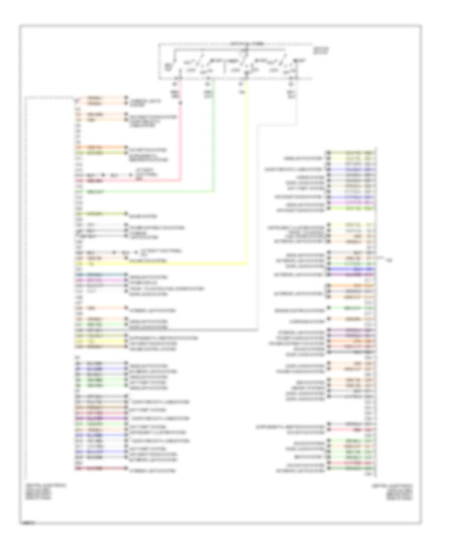
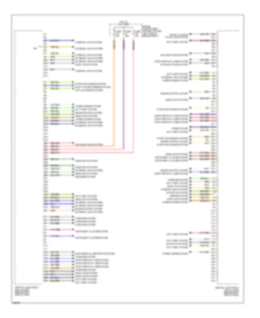
БЛОКИ УПРАВЛЕНИЯ КУЗОВОМ
Электросхема блоков управления кузовом (1 из 2) для Volvo V50 2007
Электросхема блоков управления кузовом (1 из 2) для Volvo V50 2007 - Список элементов:
- (at right kick panel) g10
- (at right kick panel) g84
- A10
- A11
- A12
- A13
- A14
- A15
- A16
- A17
- A18
- A19
- A20
- A21
- A22
- A23
- A24
- A25
- A26
- A27
- A28
- A29
- A30
- A31
- A32
- A33
- A34
- A35
- A36
- A37
- A38
- A39
- A40
- A41
- A42
- A43
- A44
- A45
- Acc
- Air conditioning system
- Anti-theft system
- B10
- B11
- B12
- B13
- B14
- B15
- B16
- B17
- B18
- B19
- B20
- B21
- B22
- B23
- B24
- B25
- B26
- B27
- B28
- B29
- B30
- B31
- B32
- C10
- C11
- C12
- C13
- C14
- C15
- C16
- C17
- C18
- C19
- C20
- C21
- C22
- C23
- C24
- C25
- C26
- C27
- C28
- C29
- C30
- C31
- C32
- C33
- C34
- C35
- C36
- C37
- C38
- C39
- C40
- C41
- C42
- C43
- C44
- C45
- C46
- Central electronic module (cem) (behind right side of dash)
- Computer data lines system
- Cruise control system
- Door locks system
- Engine controls system
- Exterior lights system
- Headlights system
- Horns system
- Hot at all times
- Ignition switch
- Instrument cluster system
- Interior lights system
- Key in
- Lock
- Memory systems
- Navigation system
- Off
- Phone module
- Power distribution system
- Power windows system
- Red
- Seats system
- Sound system
- Sound systems
- Start
- Trunk, tailgate & fuel doors system
- V50
- Warnings system
Электросхема блоков управления кузовом (2 из 2) для Volvo V50 2007
Электросхема блоков управления кузовом (2 из 2) для Volvo V50 2007 - Список элементов:
- Air conditioning system
- Anti-lock brake system
- Anti-theft system
- Central electronic module (cem) (behind right side of dash)
- Computer data lines system
- D10
- D11
- D12
- D13
- D14
- Defogger system
- Door lock system
- Door locks system
- E10
- E11
- E12
- E13
- E14
- E15
- E16
- E17
- E18
- E19
- E20
- E21
- E22
- E23
- E24
- E25
- E26
- E27
- E28
- E29
- E30
- E31
- E32
- E33
- E34
- E35
- E36
- E37
- E38
- E39
- E40
- E41
- Elect power steering system
- Engine compartment distribution box (left side of engine compt)
- Engine control system
- Exterior lights sysem
- Exterior lights system
- F10
- F11
- F12
- F13
- F14
- F15
- F16
- F17
- F18
- F19
- F20
- F21
- F22
- F23
- F24
- F25
- F26
- F27
- F28
- F29
- F30
- F31
- F32
- Fuse f16 40a
- Fuse f18 40a
- Fuse f4 60a
- G10
- G11
- G12
- G13
- G14
- G15
- G16
- G17
- G18
- G19
- G20
- G21
- G22
- G23
- G24
- G25
- G26
- G27
- G28
- G29
- G30
- G31
- G32
- H10
- H11
- H12
- H13
- H14
- H15
- H16
- H17
- H18
- H19
- H20
- H21
- H22
- H23
- H24
- H25
- H26
- H27
- H28
- H29
- H30
- H31
- H32
- Headlights system
- Horns system
- Hot at all times
- Instrument cluster system
- Interior lights system
- Mirrors system
- Navigation system
- S40
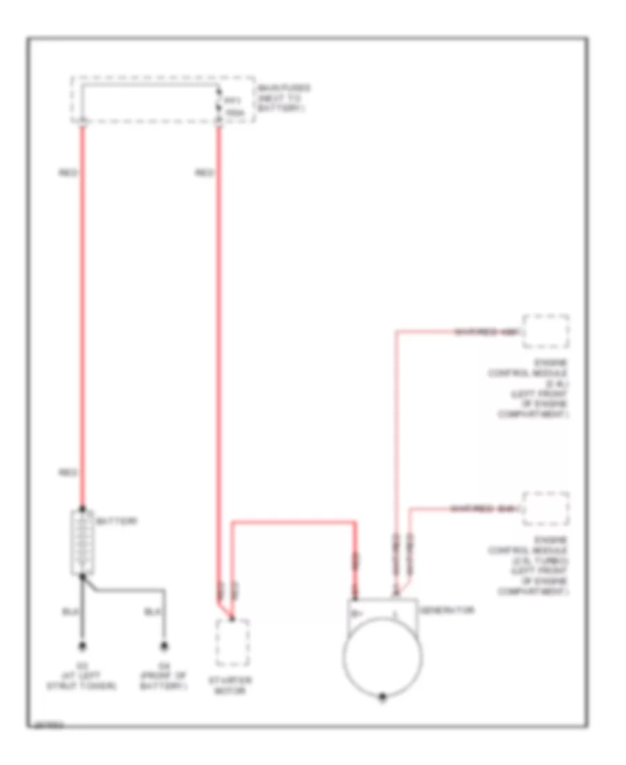
- Starting/charging system
- Trunk, tailgate & fuel door system
- Warnings system
- Wiper/washer system
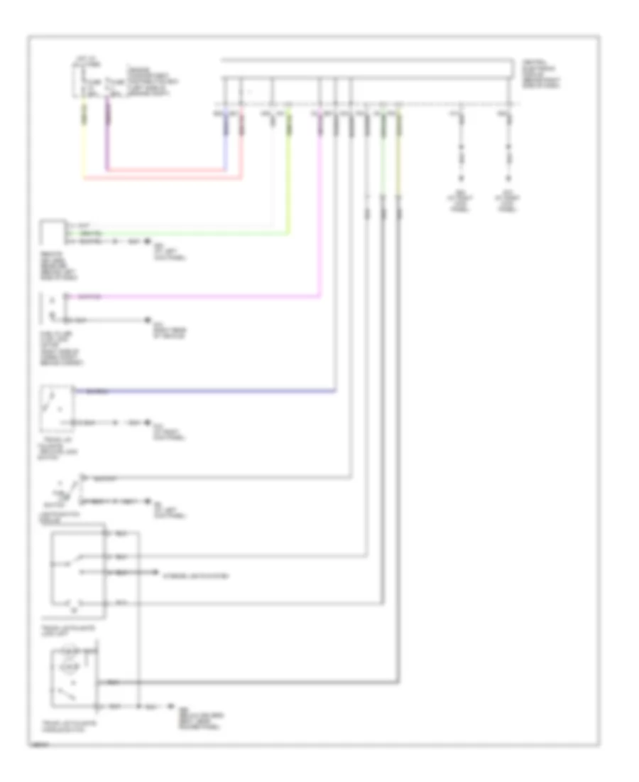
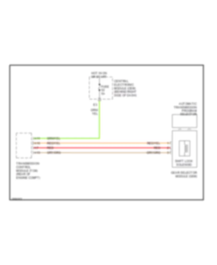
БЛОКИРОВКИ СЕЛЕКТОРА СТОЯНОЧНЫЙ ТОРМОЗ
Электросхема блокировки селектора для Volvo V50 2007
Электросхема блокировки селектора для Volvo V50 2007 - Список элементов:
- A11
- A13
- A16
- Automatic transmission program selector
- Central electronic module (cem) (behind right side of dash)
- Fuse 5a
- Gear selector module (gsm)
- Hot in on or start
- Red
- Shift lock solenoid
- Transmission control module (tcm) (rear of engine compt)
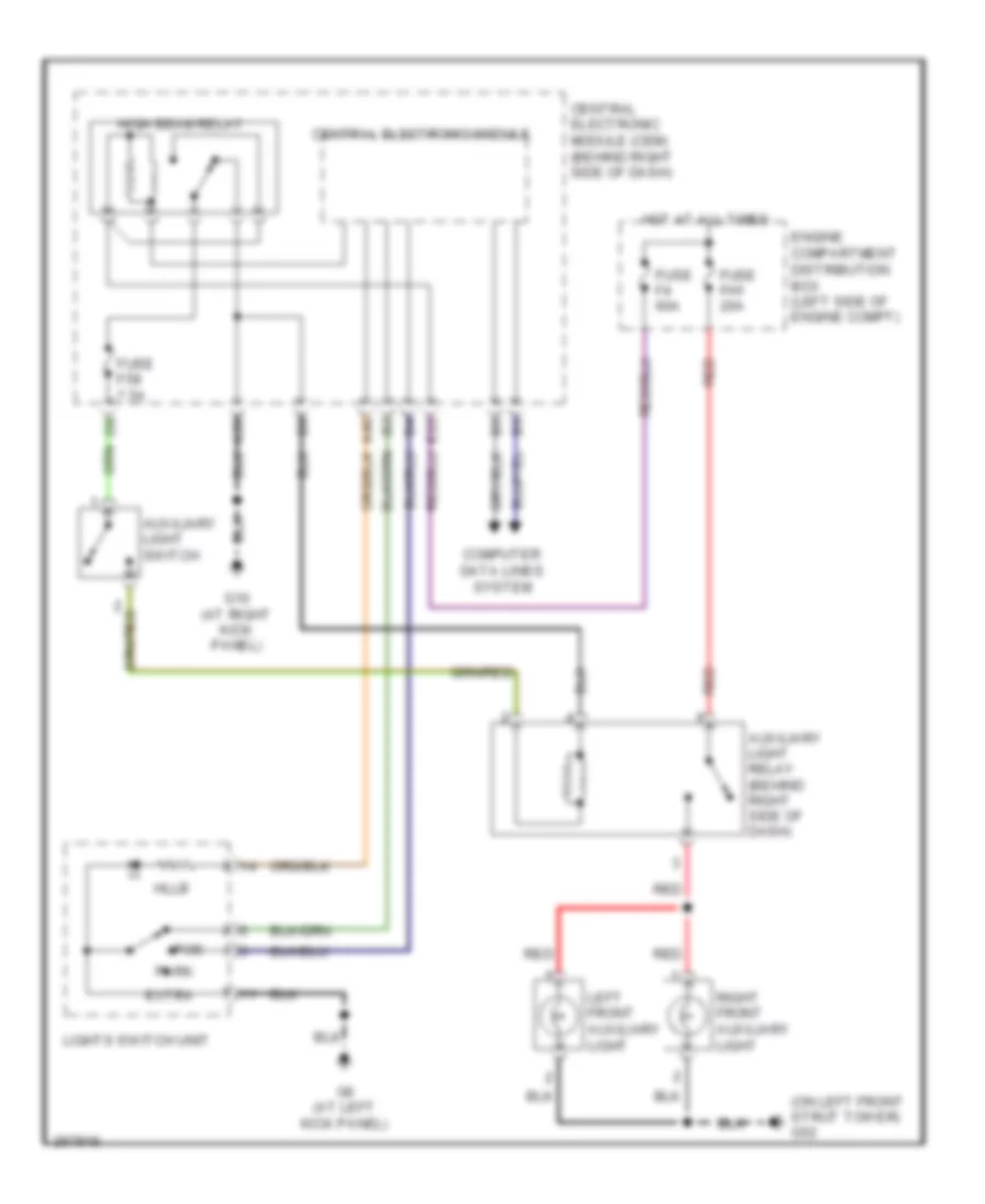
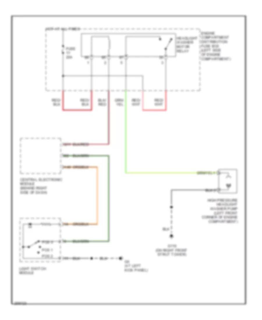
ВНЕШНЕЕ ОСВЕЩЕНИЕ
вспомогательная схема наружного освещения для Volvo V50 2007
вспомогательная схема наружного освещения для Volvo V50 2007 - Список элементов:
- (on left front strut tower) g52
- A28
- A40
- Auxiliary light relay (behind right side of dash)
- Auxiliary light switch
- Central electronic module
- Central electronic module (cem) (behind right side of dash)
- Computer data lines system
- E22
- Engine compartment distribution box (left side of engine compt)
- Extra
- Fuse f4 60a
- Fuse f58 7.5a
- Fuse fh1 20a
- G10 (at right kick panel)
- G6 (at left kick panel)
- High beam relay
- Hllb
- Hot at all times
- Left front auxiliary light
- Lights switch unit
- Park
- Pos
- Red
- Right front auxiliary light
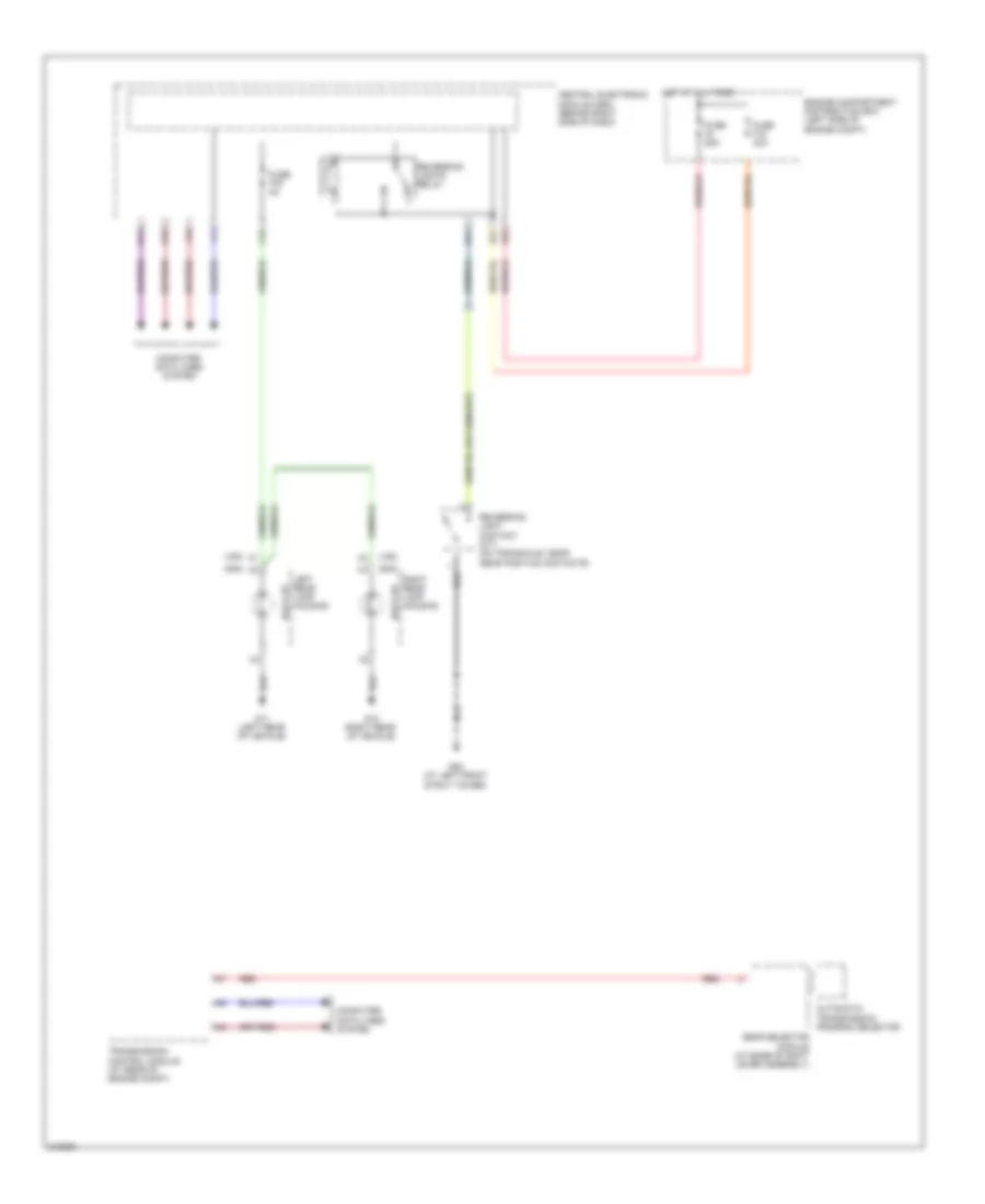
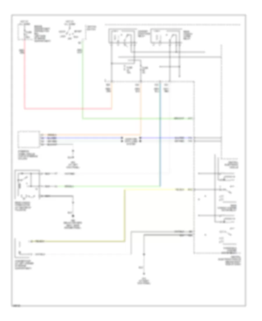
Электросхема заднего хода для Volvo V50 2007
Электросхема заднего хода для Volvo V50 2007 - Список элементов:
- (s40)
- (v50)
- Automatic transmission program selector
- Back up
- C45
- Central electronic module (cem) (behind right side of dash)
- Computer data lines system
- E14
- E21
- E22
- Engine compartment distribution box (left side of engine compt)
- F14
- F16
- Fuse f18 40a
- Fuse f4 60a
- Fuse f79 5a
- G11 (left rear of vehicle)
- G12 (right rear of vehicle)
- G14
- G15
- G52 (at left front strut tower)
- Gear selector module (at base of shift lever assembly)
- Hot at all times
- Left rear lamp housing
- Red
- Reversing light contact (m/t) (on transaxle, near gear position contacts)
- Reversing lights relay
- Right rear lamp housing
- Transmission control module (at rear of engine compt)
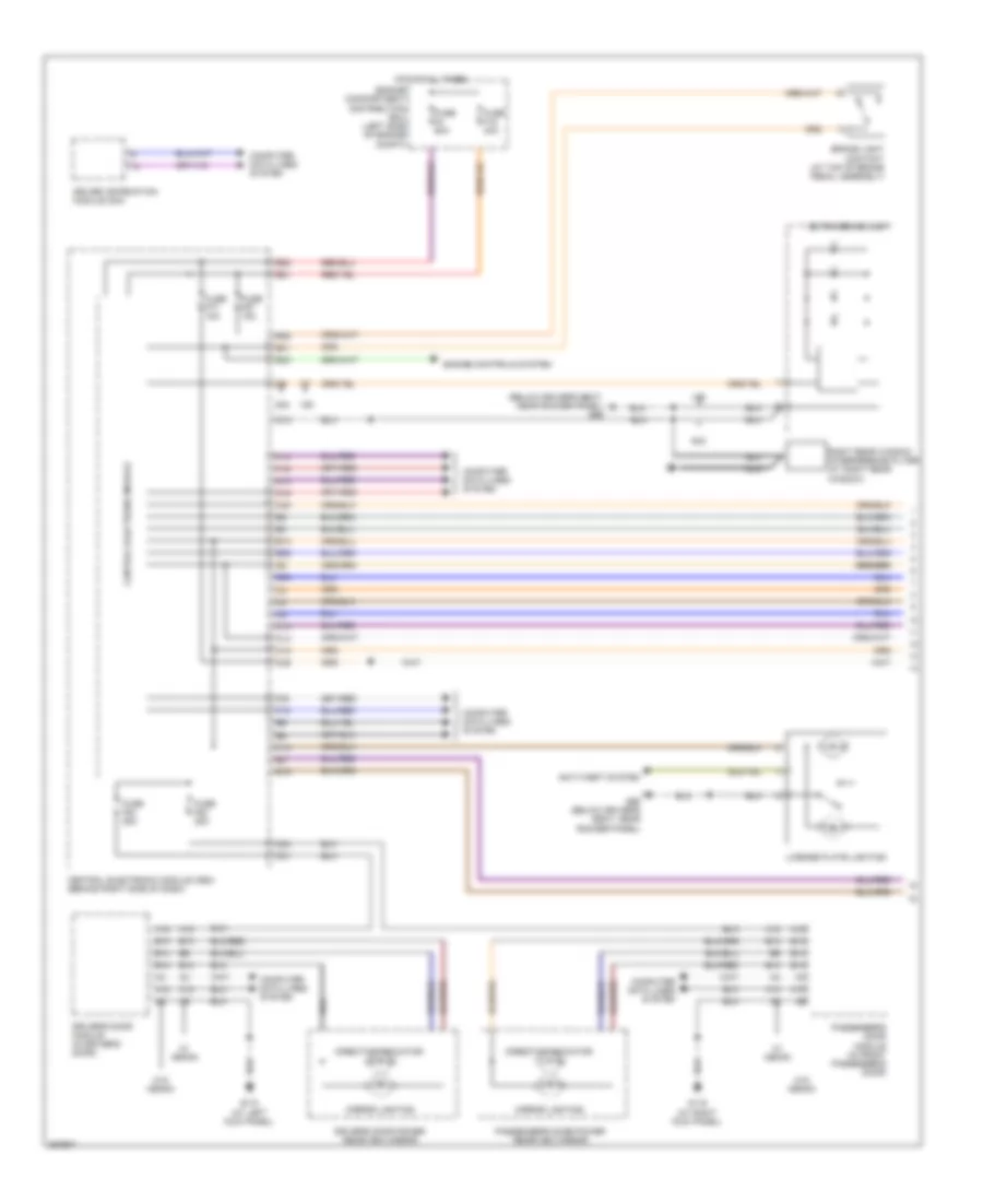
Электросхема внешнего освещения (1 из 3) для Volvo V50 2007
Электросхема внешнего освещения (1 из 3) для Volvo V50 2007 - Список элементов:
- (below driver's seat, near rocker panel) g66
- A12
- A18
- A40
- Anti-theft system
- B12
- B13
- B14
- B19
- Brake light contact (at top of brake pedal assembly)
- C10
- C12
- C13
- C14
- C22
- C24
- C31
- Central electronic module
- Central electronic module (cem) (behind right side of dash)
- Computer data lines system
- D12
- Direction indicator
- Driver information module (dim)
- Driver's door module (in driver's door)
- Driver's door power rearview mirror
- E13
- E21
- E22
- E28
- E38
- E39
- E40
- E41
- Engine compartment distribution box (left side of engine compt)
- Engine controls system
- Extra brake light
- F14
- F15
- F16
- F30
- Fuse f18 40a
- Fuse f4 60a
- Fuse f57 15a
- Fuse f77 15a
- Fuse f82 25a
- Fuse f83 25a
- G115 (at left kick panel)
- G116 (at right kick panel)
- G14
- G15
- G66 (below driver's seat, near rocker panel)
- Hot at all times
- License plate lighting
- Mirror lighting
- Nca
- Passenger's door module (in front passenger's door)
- Passenger's door power rearview mirror
- Right rear window interference filter (at right rear window)
- S40
- V50
- W/ xenon
- W/o xenon
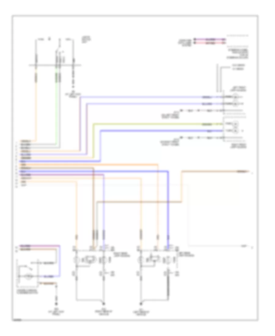
Электросхема внешнего освещения (2 из 3) для Volvo V50 2007
Электросхема внешнего освещения (2 из 3) для Volvo V50 2007 - Список элементов:
- (at left kick panel)
- Computer data lines system
- G11 (left rear of vehicle)
- G110 (on right front strut tower)
- G114 (on left front strut tower)
- G12 (right rear of vehicle)
- G6 (at left kick panel)
- G83
- Gnd
- Hazard warning flashers switch
- Left front lamp housing
- Left rear lamp housing
- Lights switch unit
- Park
- Pos 0
- Pos 1
- Pos 2
- Right front lamp housing
- Right rear lamp housing
- Steering wheel module (swm) (top of steering column)
- Stop
- Tail
- Turn
- V50 s40
- W/ xenon
- W/o xenon
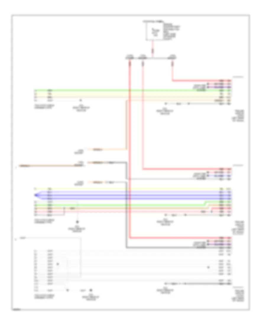
Электросхема внешнего освещения (3 из 3) для Volvo V50 2007
Электросхема внешнего освещения (3 из 3) для Volvo V50 2007 - Список элементов:
- 13-pin socket
- 4-pin socket
- 7-pin socket
- A10
- A12
- Computer data lines system
- Engine compartment distribution box (left side of engine compt)
- Fuse f14 40a
- G12 (right rear of vehicle)
- Hot at all times
- Red
- Tow hitch cable harness (13-pin)
- Tow hitch cable harness (4-pin)
- Tow hitch cable harness (7-pin)
- Trailer module (13-pin) (left rear of trunk)
- Trailer module (4-pin) (left rear of trunk)
- Trailer module (7-pin) (left rear of trunk)
ВНУТРЕННЕЕ ОСВЕЩЕНИЕ
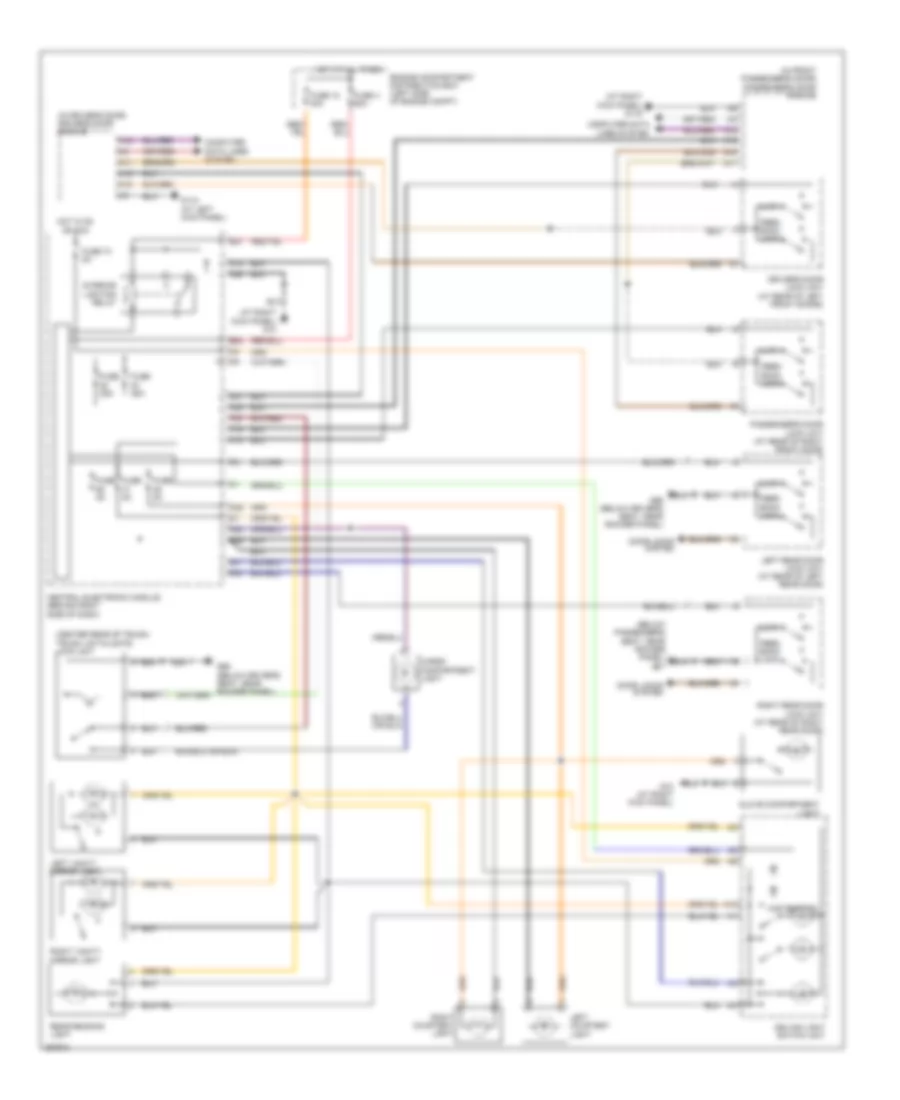
Электросхема подсветки для Volvo V50 2007
Электросхема подсветки для Volvo V50 2007 - Список элементов:
- (at right kick panel) g10
- (at right kick panel) g116
- (below passenger's seat, near rocker panel) g67
- (center rear of trunk) trunk lid/tailgate lock unit
- (in driver's door) driver's door module
- (in front passenger's door) passenger's door module
- A10
- A11
- A12
- A15
- A18
- A25
- A28
- A38
- Ajar
- C20
- C24
- C31
- Cargo compartment light
- Ceiling light switch unit
- Central electronic module (behind right side of dash)
- Computer data lines system
- D12
- Door locks system
- Driver's door lock unit (at rear of left front doors)
- E21
- E22
- Engine compartment distribution box (left side of engine compt)
- F18
- F19
- F20
- F21
- F24
- Feed- back lock
- Fuse 18 40a
- Fuse 25a
- Fuse 4 60a
- Fuse 5a
- Fuse 73 5a
- G10 (at right kick panel)
- G115 (at left kick panel)
- G66 (below driver's seat, near rocker panel)
- Glove compartment light
- Hot at all times
- Hot in on or acc
- Interior lighting relay
- Left courtesy light
- Left rear door lock unit (at rear of left rear door)
- Left vanity mirror light
- Map reading
- Passenger's door lock unit (at rear of right front door)
- Rear reading light
- Right courtesy light
- Right rear door lock unit (at rear of right rear door)
- Right vanity mirror light
Электросхема подсветки приборов для Volvo V50 2007
Электросхема подсветки приборов для Volvo V50 2007 - Список элементов:
- A12
- A13
- A38
- B21
- Central electronic module (behind right side of dash)
- Computer data lines system
- Driver door module (in driver's door)
- Driver information module
- E21
- E22
- Engine compartment distribution box (left side of engine compt)
- F15
- F30
- Fuse 18 40a
- Fuse 4 60a
- Fuse 5a
- G10 (at right kick panel)
- G6 (at left kick panel)
- Hot at all times
- Interior lighting relay
- Left rear door module (in left rear door)
- Lights switch module
- Passenger door module (in passenger's door)
- Power roof switch (c70) blis switch (s40/v40)
- Rheostat
- Right rear door module (in right rear door)
- Sym-l
ЗАЗЕМЛЕНИЕ ПОДКЛЮЧЕНИЕ МАССЫ
Электросхема подключение массы заземления для Volvo V50 2007
Электросхема подключение массы заземления для Volvo V50 2007 - Список элементов:
- Accessory electronic module, left rear lamp housing, subwoofer module (sub), remote digital audio receiver, audio module (aud) & cargo compartment 12v outlet (c70)
- Battery
- Brake control module (bcm)
- Brake control module (bcm) valves
- Central electronic module (cem), accelerator pedal sensor, rain sensor module (rsm), infotainment control module (icm), passenger side air bag stage 1 igniter, passenger side air bag stage 2 igniter, rti display, phone module (phm), multimedia module & integrated audio module (iam)
- Clutch pedal immobilizer contact, combustion pre-heater module (cpm), right gas discharge lamp slave control module, high pressure headlight washer pump, brake fluid level sensor, washer fluid level sensor, climate control system pressure monitor, wiper motor module (wmm), passenger compartment fan motor, right front lamp housing & right front fog light
- Driver's door module (ddm)
- Driver's power seat switch unit, left rear door lock unit, left rear door power window switch,
- Electric engine heater relay
- Engine control module (ecm), reversing light contact, transmission control module (tcm), front knock sensor, front right auxiliary light & front left auxiliary light
- G10 (at right kick panel)
- G102 (on front member)
- G107 (v50) (top left side of tailgate)
- G11 (left rear of vehicle)
- G110 (on right front strut tower)
- G114 (on left front strut tower)
- G115 (at left kick panel)
- G116 (at right kick panel)
- G119 (on left front strut tower)
- G12 (right rear of vehicle)
- G3 (at left strut tower)
- G4 (front of battery)
- G52 (at left front strut tower)
- G6 (at left kick panel)
- G66 (below driver's seat, near rocker panel)
- G67 (below passenger's seat, near rocker panel)
- G80 (on left front strut tower)
- G83 (at left kick panel)
- G84 (at right kick panel)
- G88 (at top of engine, near spark plugs)
- G89 (at top of engine, near spark plugs)
- Hood alarm contact, cooling fan control module, left gas discharge lamp master control module, electrical power steering module (eps), vacuum pump, horn1, horn2, siren control module (scm), left front lamp housing & left front fog light
- Ignition switch, hazard warning flashers switch, steering wheel module (swm), remote receiver module (rrx), driver information module (dim) & data link connector
- Interior lighting relay, windshield washer motor relay, comfort functions relay, power roof switch, climate control module (ccm), ceiling light switch unit, gear selector module (gsm), trunk lid/tailgate private lock switch, central electronic module (cem), recirculation damper motor module, left side temperature damper motor module, right side temperature damper motor module, defroster damper motor module, floor/ventilation damper motor module, interior temperature sensor, air quality sensor, cellular phone handsfree control module, auto-dimming rearview mirror, manual reverse interlock solenoid, front 12v outlet, rear 12v outlet, high beam relay, blis switch, ceiling light, rain sensor module, glove compartment lighting, front mass movement sensor module, right vanity mirror lighting, infotainment relay, rear window wiper relay, rear window washer motor relay, fuel pump relay, washer pump, rear reading light, integrted audio module, sunroof control module, left vanity mirror lighting (s40/v50)
- Lights switch unit, steering column lock module (scl), left front lamp housing, right front lamp housing, data link connector,
- Oil trap ptc resistor, spark plugs & ignition coils
- Parking assistance module (pam) convertible roof module, trailer module (trm), accessory electronic module, fuel filler flap lock motor, right rear lamp housing, remote digital audio receiver, global position system module (gps), tow hitch cable harness & cargo compt 12v outlet (s40/v50)
- Passenger door module (pdm), fuel pump control module & fuel pump
- Passenger's power seat switch unit, right rear door module, power seat module, rear mass movement sensor, keyless vehicle module (kvm), occupant weight sensor (ows) passenger side side airbag igniter, right rear door lock unit, right rear door power window switch, right rear locking switch, right rear unlocking switch, right rear seat entry switch, right rear reading light, differential electronic module (dem), passenger side seat heating module
- Power seat module (psm), auxiliary heater fuel pump, driver's side seat heating module, driver's side side airbag igniter, driver lap belt tensioner, left rear door module, heated rear window & license plate lighting (s40), trunklid/tailgate handle switch, trunklid/tailgate lock unit, left rear locking contact, left rear unlocking contact, left rear seat entry switch, rear window wiper motor (v50), auxiliary brake light (v50), left rear reading light, left vanity mirror light (c70)
- Spark plugs & ignition coils
- Trunk lid/tailgate lock unit,
- Window antenna amplifier, roof
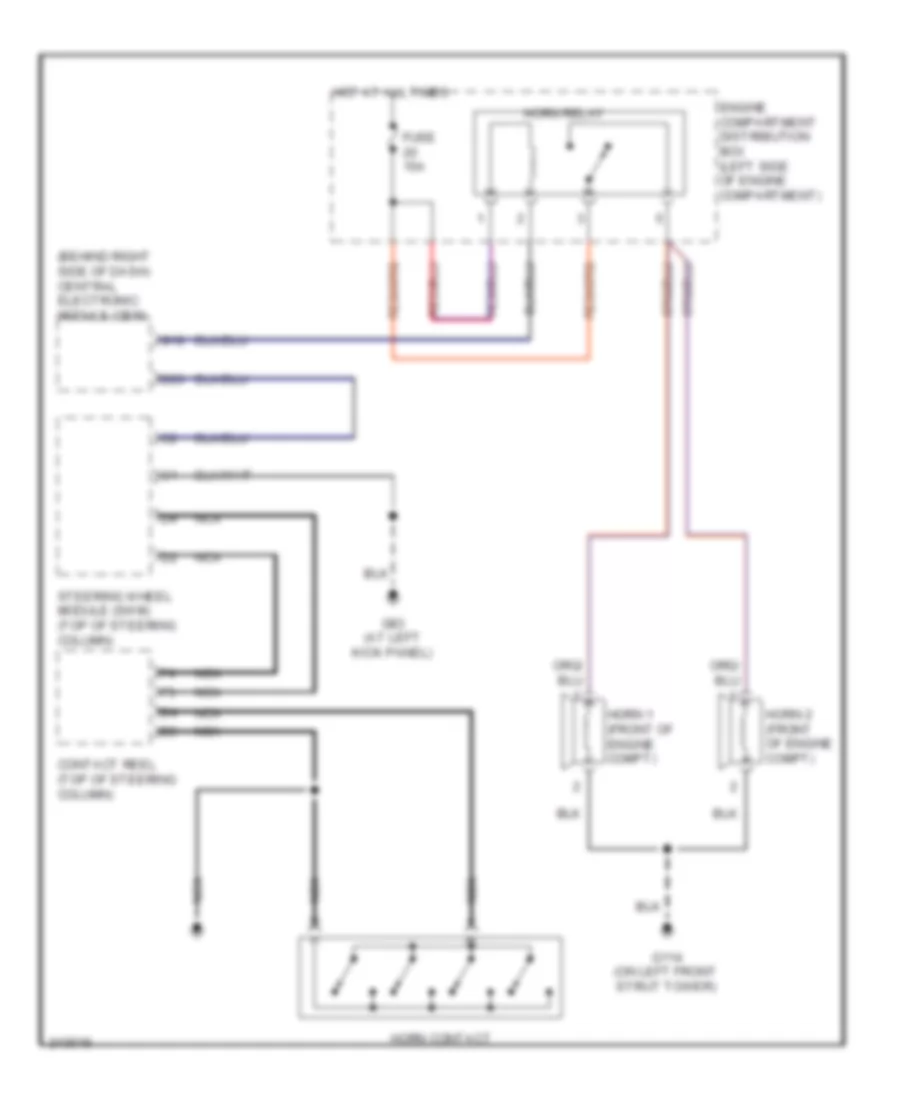
Звуковой сигнал Гудок
Электросхема звукового сигнал Гудка для Volvo V50 2007
Электросхема звукового сигнал Гудка для Volvo V50 2007 - Список элементов:
- (behind right side of dash) central electronic module (cem)
- B26
- Contact reel (top of steering column)
- Engine compartment distribution box (left side of engine compartment)
- Fuse 15a
- G114 (on left front strut tower)
- G18
- G83 (at left kick panel)
- Horn 1 (front of engine compt)
- Horn 2 (front of engine compt)
- Horn contact
- Horn relay
- Hot at all times
- Nca
- Steering wheel module (swm) (top of steering column)
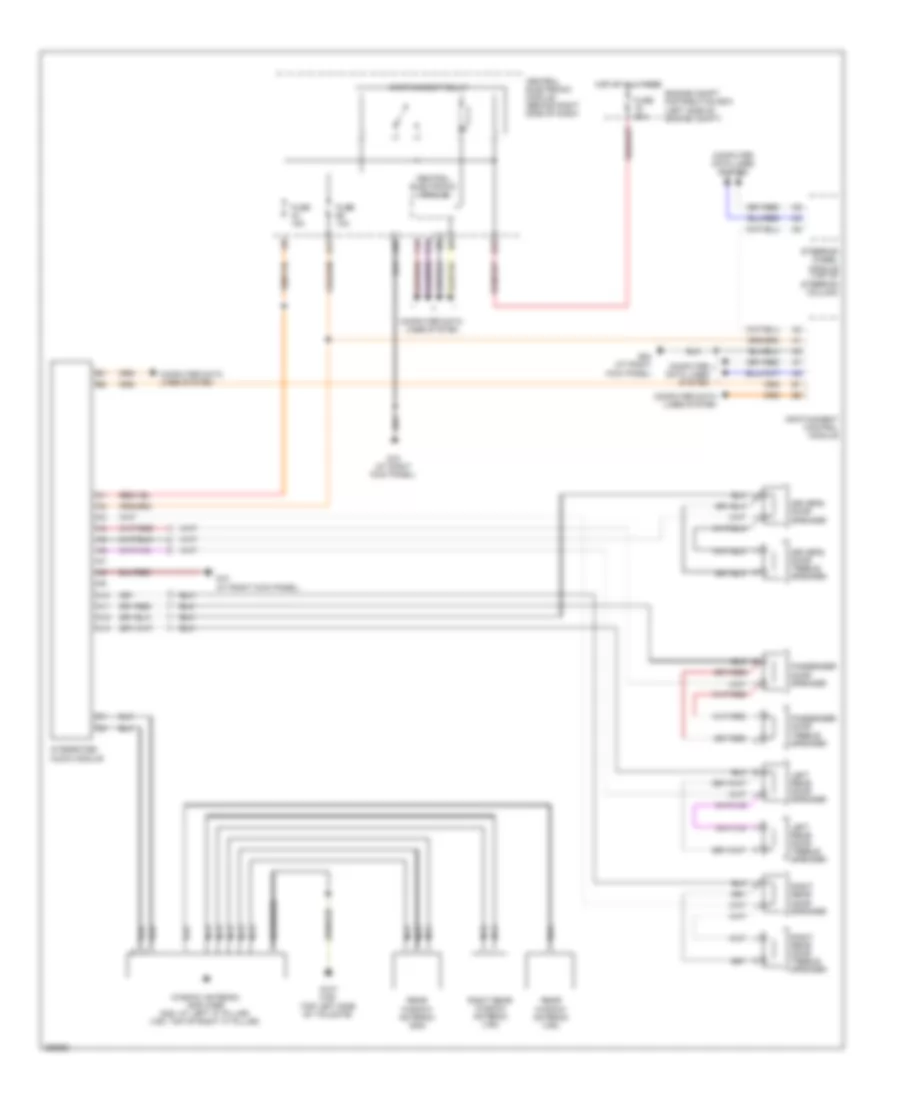
Магнитола Мультимедия
Эдектросхема магнитолы. Базовая комплектация. для Volvo V50 2007
Эдектросхема магнитолы. Базовая комплектация. для Volvo V50 2007 - Список элементов:
- A10
- A11
- A12
- A13
- A21
- A28
- Central electronic module
- Central electronic module (behind right side of dash)
- Computer data lines system
- Driver's door speaker
- Driver's door treble speaker
- E23
- Engine compt distribution box (left side of engine compt)
- F14
- F16
- Fuse 10a
- Fuse 15a
- Fuse 30a
- G10 (at right kick panel)
- G107 (v50) (top left side of tailgate)
- G84 (at right kick panel)
- Hot at all times
- Infotainment control module
- Infotainment relay
- Integrated audio module
- Left rear door speaker
- Left rear door treble speaker
- Nca
- Passenger door speaker
- Passenger door treble speaker
- Rear window antenna (s40)
- Rear window antenna (v50)
- Right rear door speaker
- Right rear door treble speaker
- Right rear window antenna (v50)
- Screened
- Steering wheel module (top of steering column)
- Window antenna amplifier (s40: at left "c" pillar) (v50: top of right "c" pillar)
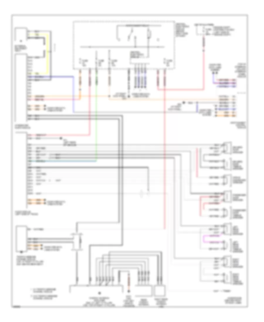
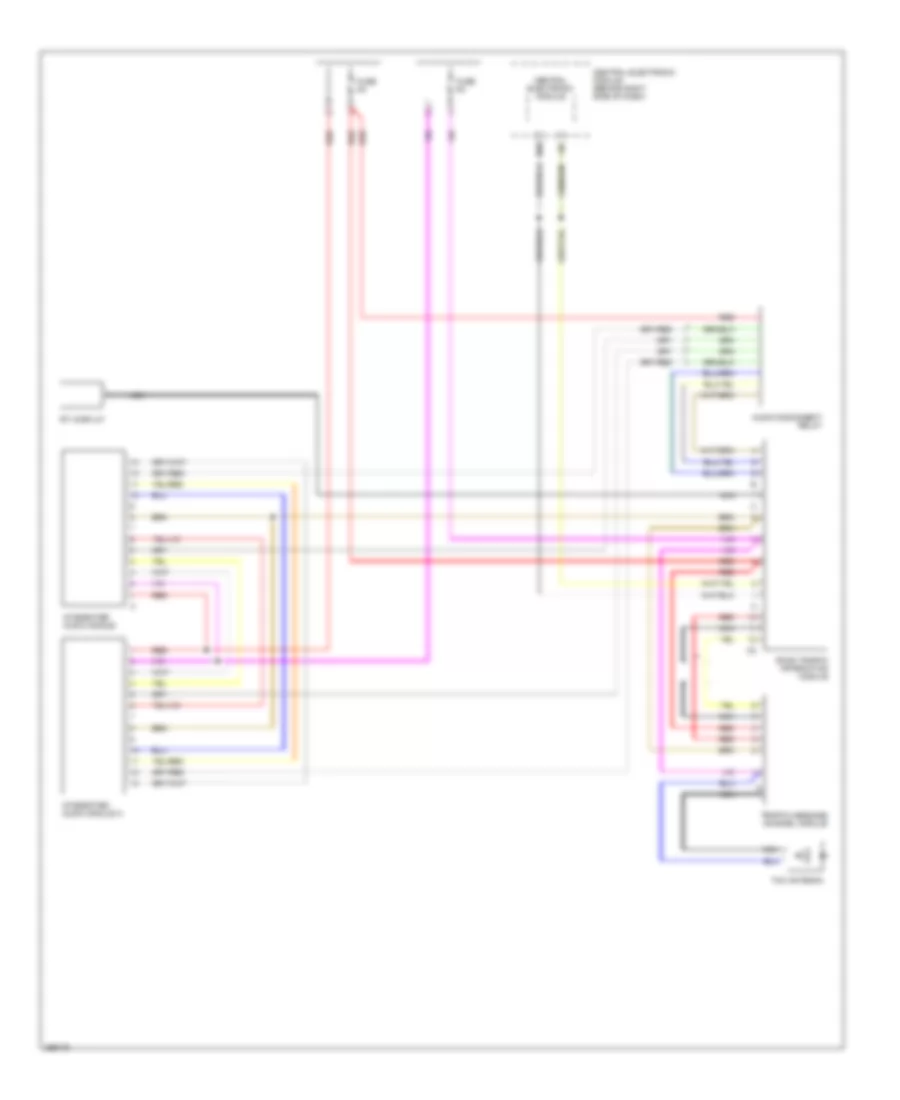
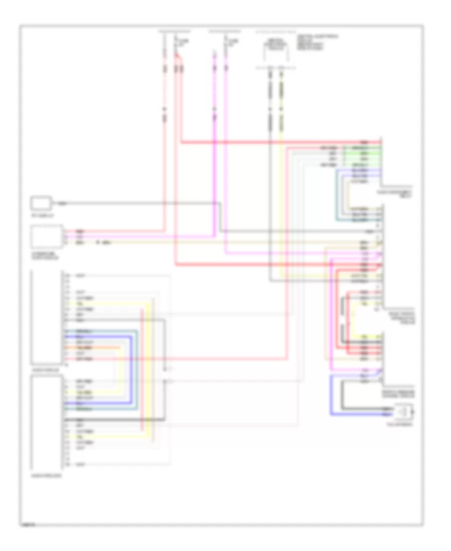
Электросхема премиум магнитолы для Volvo V50 2007
Электросхема премиум магнитолы для Volvo V50 2007 - Список элементов:
- (at right kick panel) g10
- (top of steering column) steering wheel module
- A10
- A11
- A12
- A13
- A14
- A21
- A28
- Audio module (left side of trunk)
- B10
- B11
- B12
- B13
- B14
- B15
- B16
- C23
- C40
- C44
- Central electronic module
- Central electronic module (behind right side of dash)
- Computer data lines system
- Driver's door speaker
- Driver's door treble speaker
- E23
- Engine compt distribution box (left side of engine compt)
- External equipment input
- F14
- F16
- Fuse 10a
- Fuse 15a
- Fuse 30a
- Fuse 5a
- G107 (v50) (top left side of taiilgate)
- G11 (left rear of vehicle)
- G84 (at right kick panel)
- Hot at all times
- Infotainment control module
- Infotainment relay
- Integrated audio module
- Left rear door speaker
- Left rear door treble speaker
- Microphone (center front of roof liner)
- Middle dashboard speaker
- Nca
- Passenger door speaker
- Passenger door treble speaker
- Rear window antenna
- Right rear door speaker
- Right rear door treble speaker
- Right rear window antenna (v50)
- S40
- Screened
- Traffic message channel module (v50: at right "c" pillar) (s40: behind rear seat)
- V50
- W/ traffic message channel module
- W/o traffic message channel module
- Window antenna amplifier (s40: at left "c" pillar) (v50: top of right "c" pillar)
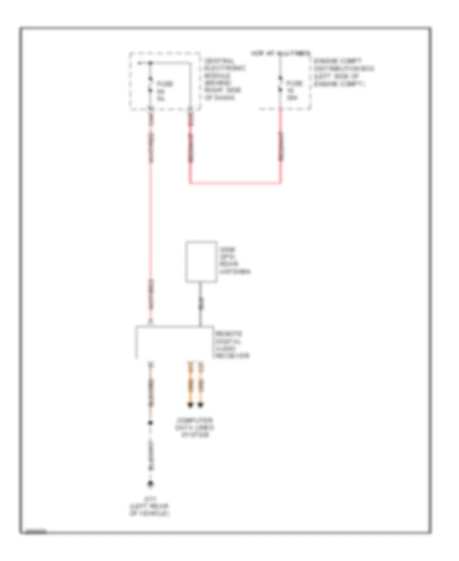
Электросхема спутникового радио для Volvo V50 2007
Электросхема спутникового радио для Volvo V50 2007 - Список элементов:
- C44
- Central electronic module (behind right side of dash)
- Computer data lines system
- E23
- Engine compt distribution box (left side of engine compt)
- Fuse 30a
- Fuse 5a
- G11 (left rear of vehicle)
- Gsm/ gps/ rdar antenna
- Hot at all times
- Remote digital audio reciever
Навигация GPS Парктроники
Электросхема навигации GPS, стандартная комплектация для Volvo V50 2007
Электросхема навигации GPS, стандартная комплектация для Volvo V50 2007 - Список элементов:
- Audio disconnect relay
- Central electronic module
- Central electronic module (behind right side of dash)
- Fuse 5a
- H20
- Integrated audio module
- Integrated audio module a
- Nca
- Red
- Road traffic information module
- Rti display
- Tmc antenna
- Traffic message channel module
Электросхема навигации GPS, Премиум класс для Volvo V50 2007
Электросхема навигации GPS, Премиум класс для Volvo V50 2007 - Список элементов:
- Audio disconnect relay
- Audio module
- Audio module b
- Central electronic module
- Central electronic module (behind right side of dash)
- Fuse 5a
- H20
- Integrated audio module
- Nca
- Red
- Road traffic information module
- Rti display
- Tmc antenna
- Traffic message channel module
Электросхема парктроников для Volvo V50 2007
Электросхема парктроников для Volvo V50 2007 - Список элементов:
- (on front bumper)
- (on rear bumper)
- A10
- A11
- A12
- A13
- A14
- C10
- C11
- C38
- Central electronic module (behind right side of dash)
- Computer data
- Front parking assistance sensor 5
- Front parking assistance sensor 6
- Front parking assistance sensor 7
- Front parking assistance sensor 8
- Fuse f51 10a
- G12 (right rear of vehicle)
- Hot in on or start
- Lines system
- Parking assistance control module (at right rear corner of cargo compartment)
- Rear parking assistance sensor 1
- Rear parking assistance sensor 2
- Rear parking assistance sensor 3
- Rear parking assistance sensor 4
- Red
- Trailer module (trm) (left rear of trunk)
схема информации о дорожном движении для Volvo V50 2007
схема информации о дорожном движении для Volvo V50 2007 - Список элементов:
- (at right kick panel) g84
- (top of steering column) steering wheel module (swm)
- A21
- A28
- A29
- B10
- C44
- Central electronic module
- Central electronic module (behind right side of dash)
- Computer data lines system
- F14
- F16
- Fuse f43 15a
- Fuse f64 5a
- Fuse f65 5a
- Fuse f66 10a
- G10 (at right kick panel)
- G12 (right rear of vehicle)
- Global positioning system module (gps) (left side of trunk)
- Hot at all times
- Infotainment control module (icm)
- Infotainment relay
- Multimedia module (mmm)
- Nca
- Pnk
- Red
- Rti display
- Rti gps antenna (center rear of roof)
- Rti remote control ir sensor (top center of dash)
Подогрев стекол и зеркал
Электросхема подогрева стекол и зеркал для Volvo V50 2007
Электросхема подогрева стекол и зеркал для Volvo V50 2007 - Список элементов:
- (in front passenger's door)
- A12
- A14
- A17
- A18
- A42
- Acc
- B11
- B12
- C24
- C31
- Central electronic module (behind right side of dash)
- Central electronic module (cem) (behind right side of dash)
- Climate control module
- Computer data lines system
- Driver's door module (ddm) (in driver's door)
- Driver's door rear view mirror
- E30
- Engine compartment distribution box (left side of engine compartment)
- Fuse 25a
- Fuse 30a
- G115 (at left kick panel)
- G116 (at right kick panel)
- G84 (at right kick panel)
- Heated rear view mirror
- Heated rear window
- Heated rear window relay
- Heated rear window/door mirrors switch
- Hot at all times
- Ignition switch
- Left rear window interference filter
- Lock
- Nca
- Off
- Passenger door module (pdm)
- Passenger door rear view mirror
- Right rear window interference filter
- Start
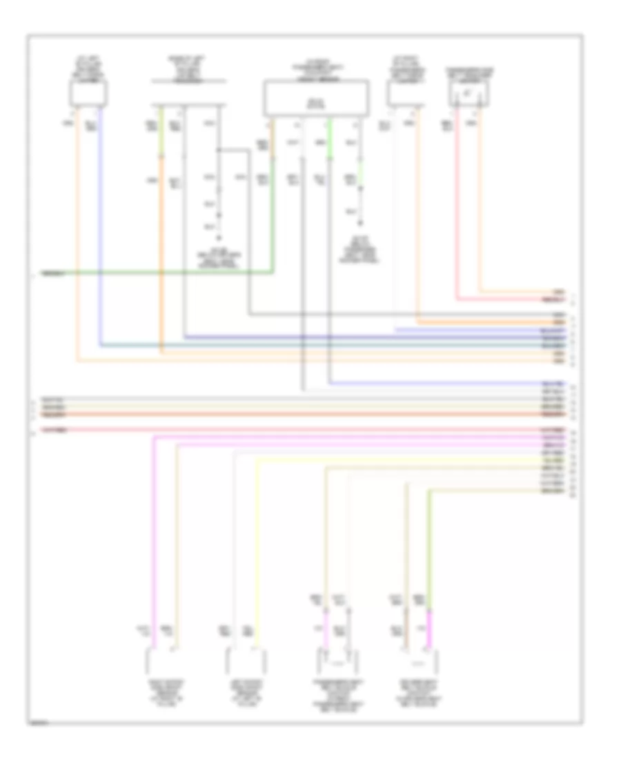
ПОДУШКИ БЕЗОПАСНОСТИ AIR BAG
Электросхема подушек безопасности SRS AirBag (1 из 3) для Volvo V50 2007
Электросхема подушек безопасности SRS AirBag (1 из 3) для Volvo V50 2007 - Список элементов:
- (under driver's seat) driver's seat position sensor
- (under front passenger's seat) passenger's seat position sensor
- Central electronic module (behind right side of dash)
- Comfort functions relay
- Contact reel
- Driver side airbag igniter (in steering wheel)
- Driver side airbag igniter stage 2 (in steering wheel)
- Fuse 44 10a
- Fuse 49 10a
- G31/10 (at right kick panel)
- G31/84 (at right kick panel)
- Gnd
- Hot at all times
- Hot in start and run
- Left front impact sensor (behind left side of front bumper)
- Nca
- Passenger airbag igniter stage 2 (behind right side of dash)
- Passenger side air bag switch
- Passenger side airbag igniter (behind right side of dash)
- Right front impact sensor (behind right side of front bumper)
- Solid state
- Steering column igniter (top of steering column)
Электросхема подушек безопасности SRS AirBag (2 из 3) для Volvo V50 2007
Электросхема подушек безопасности SRS AirBag (2 из 3) для Volvo V50 2007 - Список элементов:
- (at left "b" pillar) driver's belt force limiter
- (at right "b" pillar)
- (base of left "b" pillar) driver's lap belt tensioner
- (in front passenger's seat) occupant weight sensor
- Driver's seat belt buckle contact (in driver's seat belt buckle)
- G31/66 (below driver's seat, near rocker panel)
- G31/67 (below passenger seat, near rocker panel)
- Left b-post side impact sensor (at left "b" pillar)
- Nca
- Passenger's belt force limiter
- Passenger's seat belt buckle contact (in front passenger's seat belt buckle)
- Passenger's side belt tensioner igniter
- Right b-post side impact sensor (at right "b" pillar)
- Solid state
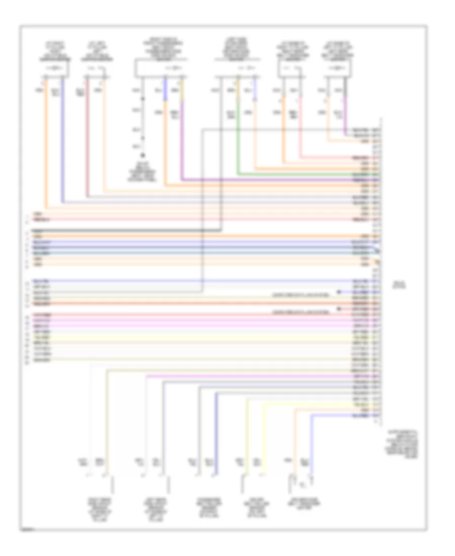
Электросхема подушек безопасности SRS AirBag (3 из 3) для Volvo V50 2007
Электросхема подушек безопасности SRS AirBag (3 из 3) для Volvo V50 2007 - Список элементов:
- (at base of left "c" pillar) left rear belt tensioner igniter
- (at base of right "c" pillar) right rear belt tensioner igniter
- (at left "c" pillar) left inflatable curtain igniter
- (at right "c" pillar) right inflatable curtain igniter
- (left side of driver's seat back) driver's side side air bag igniter
- (right side of front passenger's seat back) passenger's side side air bag igniter
- Computer data link system
- Driver belt roller sensor (on left "b" pillar)
- Driver's side belt tensioner igniter
- G31/67 (below passenger's seat, near rocker panel)
- Left rear side impact sensor (at base of left "c" pillar)
- Nca
- Passenger belt roller sensor (on right "b" pillar)
- Right rear side impact sensor (at base of right "c" pillar)
- Solid state
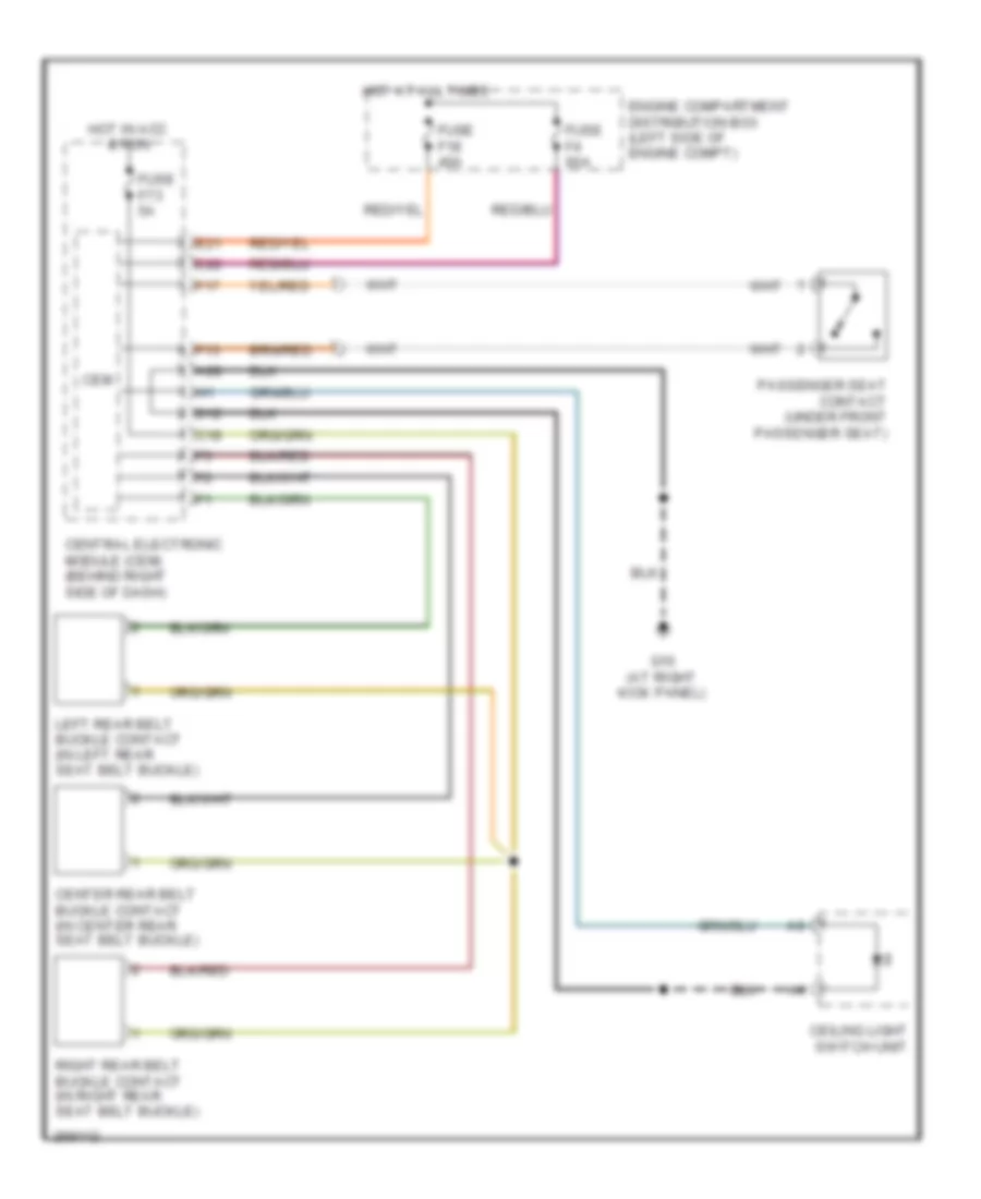
ПРЕДУПРЕЖДАЮЩИЕ СИСТЕМЫ
Электросхема предупреждающей системы для Volvo V50 2007
Электросхема предупреждающей системы для Volvo V50 2007 - Список элементов:
- A28
- C18
- Ceiling light switch unit
- Cem
- Center rear belt buckle contact (in center rear seat belt buckle)
- Central electronic module (cem) (behind right side of dash)
- D12
- E21
- E22
- Engine compartment distribution box (left side of engine compt)
- F13
- F17
- Fuse f18 40a
- Fuse f4 60a
- Fuse f73 5a
- G10 (at right kick panel)
- Hot at all times
- Hot in acc & run
- Left rear belt buckle contact (in left rear seat belt buckle)
- Passenger seat contact (under front passenger seat)
- Right rear belt buckle contact (in right rear seat belt buckle)
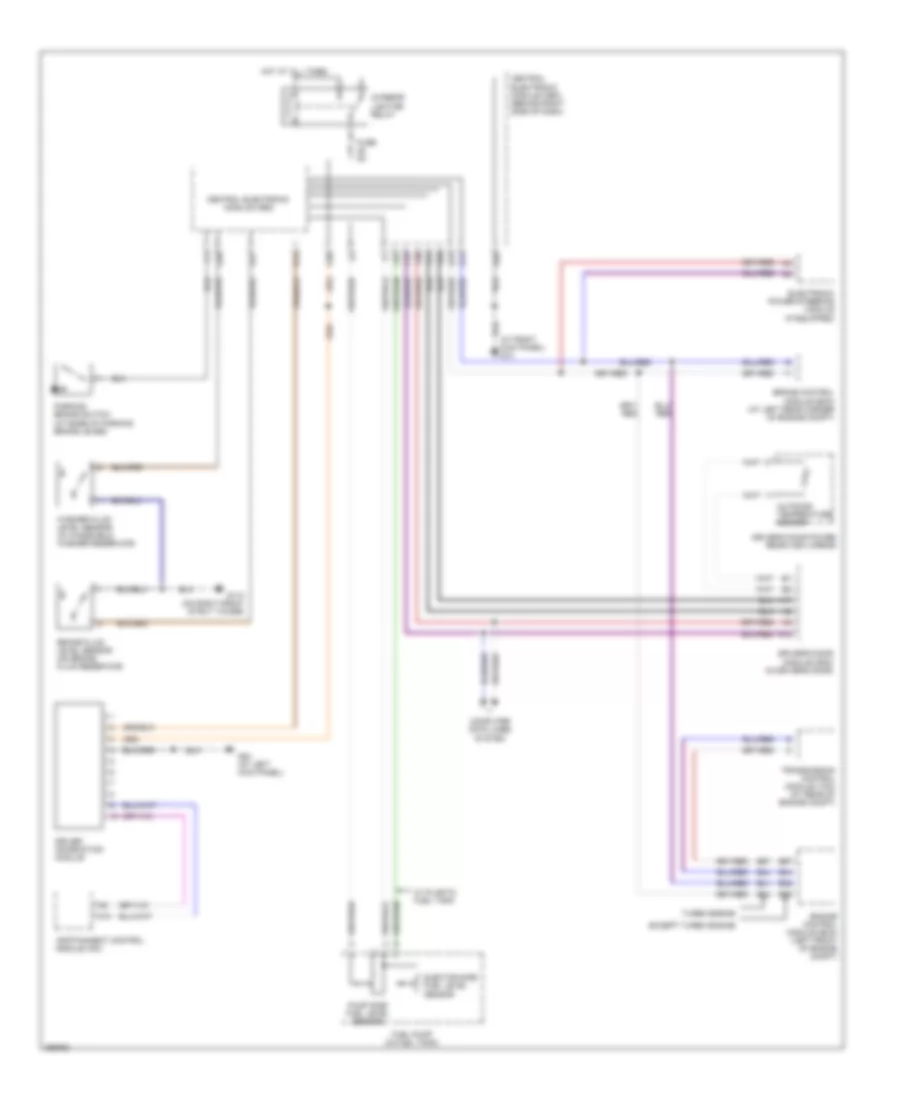
ПРИБОРНАЯ ПАНЕЛЬ
Электросхема панели приборов для Volvo V50 2007
Электросхема панели приборов для Volvo V50 2007 - Список элементов:
- (at right kick panel) g10
- A10
- A12
- A17
- A28
- A38
- B14
- B41
- B44
- B45
- B54
- B57
- B58
- Brake control module (bcm) (at left rear corner of engine compt)
- Brake fluid level sensor (on brake fluid reservoir)
- Central electronic module (cem)
- Central electronic module (cem) (behind right side of dash)
- Computer data lines system
- Driver information module
- Driver's door module (ddm) (in driver's door)
- Driver's door power rear-view mirror
- Ejector side fuel level sensor
- Electronic power steering module (if equipped)
- Engine control module (ecm) (left front of engine compt)
- Except turbo engine
- F15
- F25
- F28
- F30
- F31
- Fuel pump (in fuel tank)
- Fuse 5a
- G110 (on right front strut tower)
- G14
- G15
- G27
- G28
- G83 (at left kick panel)
- Hot at all times
- Infotainment control module (icm)
- Interior lighting relay
- Outdoor temperature sensor
- Parking brake switch (at base of parking brake lever)
- Pump side fuel level sensor
- Transmission control module (tcm) (at rear of engine compt)
- Turbo engine
- W/ plastic fuel tank
- Washer fluid level sensor (in windshield washer reservoir)
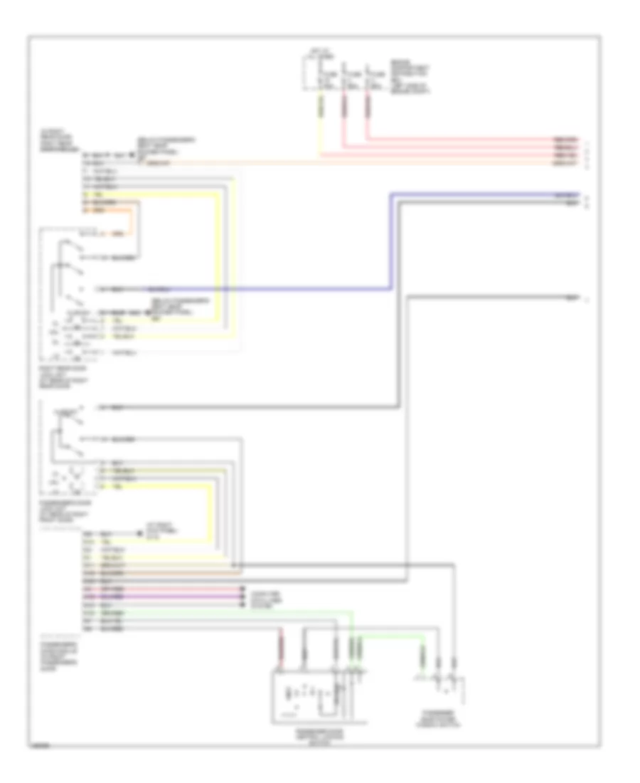
ПРИВОД ЗЕРКАЛ
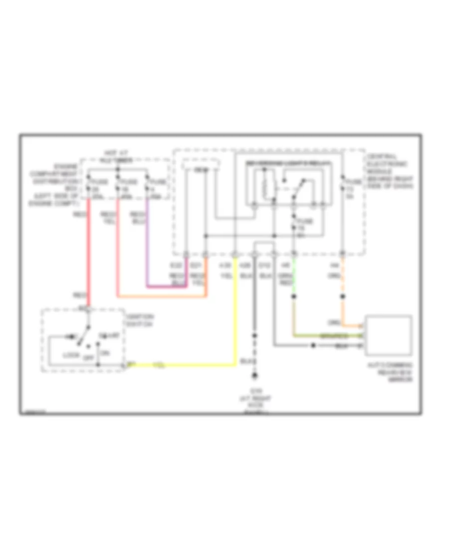
автомобиль, затемняющий схему зеркала заднего обзора для Volvo V50 2007
автомобиль, затемняющий схему зеркала заднего обзора для Volvo V50 2007 - Список элементов:
- A28
- A30
- Acc
- Auto dimming rearview mirror
- Cem
- Central electronic module (behind right side of dash)
- D12
- E21
- E22
- Engine compartment distribution box (left side of engine compt)
- Fuse 15a
- Fuse 40a
- Fuse 5a
- Fuse 60a
- G10 (at right kick panel)
- Hot at all times
- Ignition switch
- Lock
- Off
- Red
- Reversing lights relay
- Start
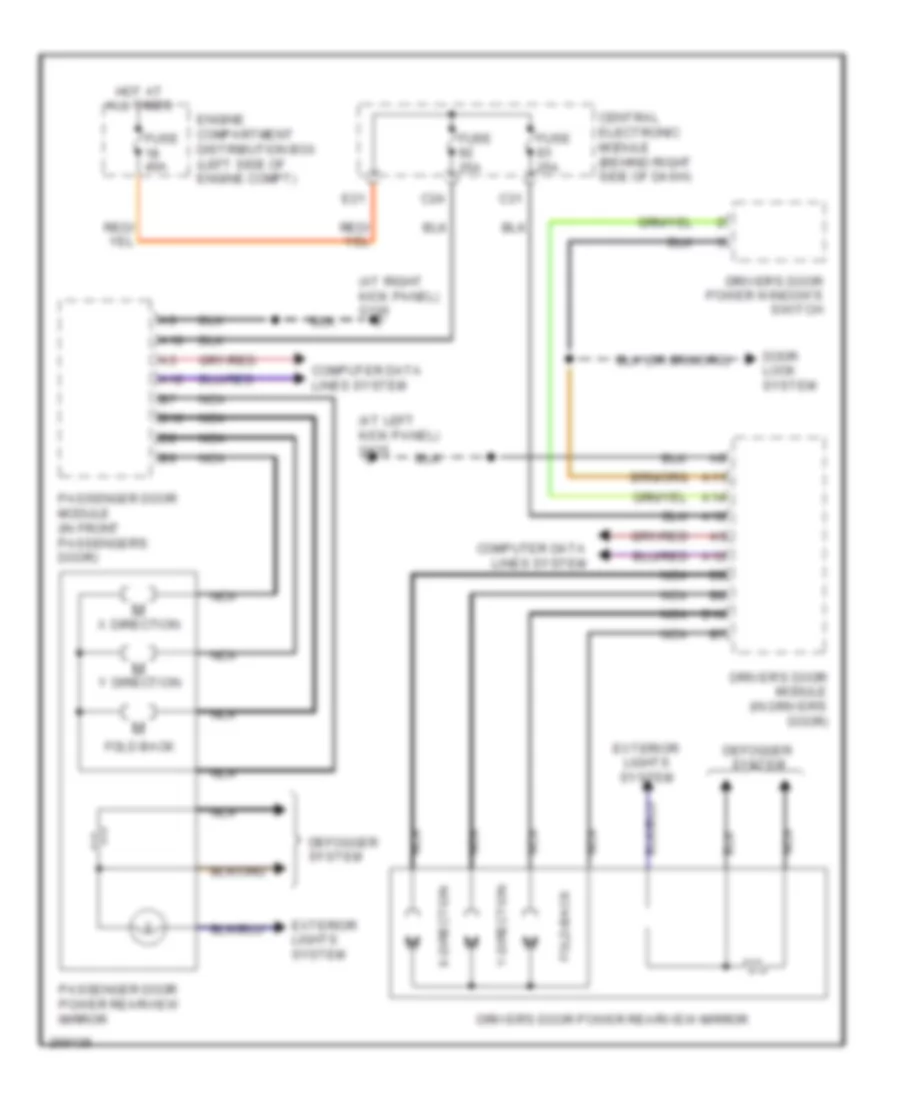
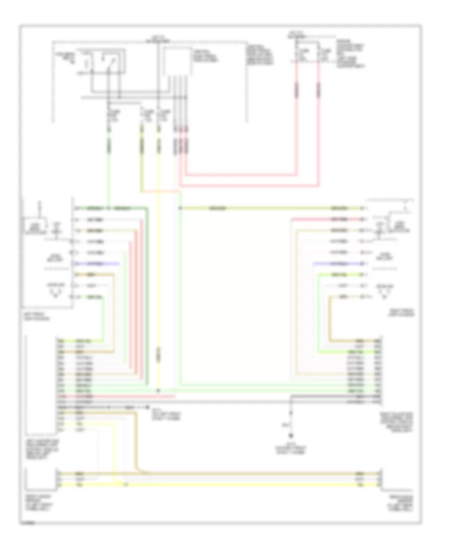
Электросхема привода зеркал для Volvo V50 2007
Электросхема привода зеркал для Volvo V50 2007 - Список элементов:
- (at left kick panel) g115
- (at right kick panel) g116
- A11
- A12
- A14
- A18
- B10
- C24
- C31
- Central electronic module (behind right side of dash)
- Computer data lines system
- Defogger system
- Door lock system
- Driver's door module (in driver's door)
- Driver's door power rearview mirror
- Driver's door power window's switch
- E21
- Engine compartment distribution box (left side of engine compt)
- Exterior lights system
- Fold back
- Fold-back
- Fuse 25a
- Fuse 40a
- Hot at all times
- M x-direction
- M y-direction
- Nca
- Passenger door module (in front passenger's door)
- Passenger door power rearview mirror
- X direction
- Y direction
ПРИВОД ЛЮКА И КРЫШИ
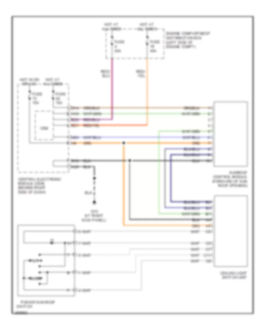
Электросхема привода люка или крыши для Volvo V50 2007
Электросхема привода люка или крыши для Volvo V50 2007 - Список элементов:
- A28
- C11
- Ceiling light switch unit
- Cem
- Central electronic module (cem) (behind right side of dash)
- D12
- D14
- E21
- E22
- Engine compartment distribution box (left side of engine compt)
- Fuse 15a
- Fuse 40a
- Fuse 60a
- G10 (at right kick panel)
- H18
- H20
- Hot at all times
- Hot in on or acc
- Power sun roof
- Slide
- Sunroof control module (forward of sun roof opening)
- Switch
- Tilt
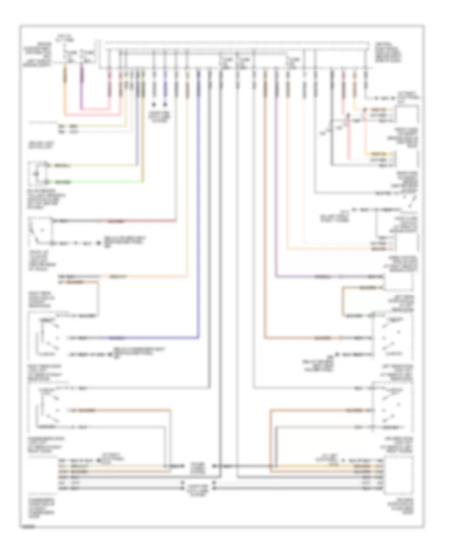
ПРИВОД СТЕКЛОПОДЪЕМНИКОВ
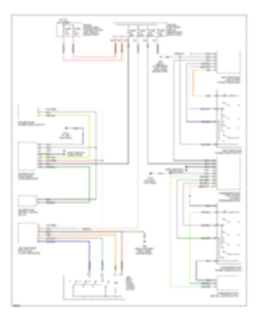
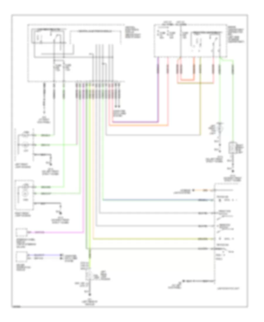
Электросхема стеклоподъемников для Volvo V50 2007
Электросхема стеклоподъемников для Volvo V50 2007 - Список элементов:
- A11
- A12
- A13
- A14
- A16
- A18
- C21
- C24
- C27
- C31
- Central electronic module (behind right side of dash)
- Computer data lines system
- Driver's door central locking switch
- Driver's door module (ddm) (in driver's door)
- Driver's door power window switch
- E20
- E21
- Engine compartment distribution box (left side of engine compt)
- Fuse 20a
- Fuse 25a
- Fuse 40a
- Fuse 60a
- G115 (at left kick panel)
- G116 (at right kick panel)
- G66 (below driver's seat, near rocker panel)
- G67 (below passenger's seat, near rocker panel)
- Hot at all times
- Left rear door module (ldm) (in left rear door)
- Left rear door power window switch
- Passenger's door central locking switch
- Passenger's door module (pdm) (in front passenger's door)
- Passenger's door power window switch
- Right rear door module (rdm) (in right rear door)
- Right rear door power window switch
Противоугонная система Сигнализация
Электросхема открывания авто для Volvo V50 2007
Электросхема открывания авто для Volvo V50 2007 - Список элементов:
- (at left kick panel) g115
- (at right kick panel) g10
- (at right kick panel) g116
- (below driver's seat near rocker panel) g66
- (below passenger's seat near rocker panel) g67
- A11
- A12
- A15
- A18
- A28
- Ajar sw
- B28
- C21
- C24
- C27
- C31
- Ceiling light switch unit
- Central electronic module (cem) (behind right side of dash)
- Computer data lines system
- D10
- Driver's door lock unit (at rear of left front doors)
- Driver's door module (in driver's door)
- E21
- E22
- E36
- Engine compartment distribution box (left side of engine compt)
- F15
- F18
- F19
- F20
- F21
- F24
- F30
- Front mass movement sensor module (center of roof)
- Fuse 10a
- Fuse 25a
- Fuse 40a
- Fuse 60a
- G114 (on left front strut tower)
- G19
- G66 (below driver's seat near rocker panel)
- H17
- H19
- H21
- Hood alarm contact (at front of engine compt)
- Hot at all times
- Left rear door lock unit (at rear of left rear door)
- Left rear door module (in left rear door)
- Lock sw
- Passenger's door lock unit (at rear of right front door)
- Passenger's door module (in front passenger's door)
- Power window system
- Rear mass movement sensor (center rear of roof)
- Right rear door lock unit (at rear of right rear door)
- Right rear door module (in right rear door)
- Siren control module (scm) (at right rear of engine compt)
- Solar sensor taillight sensor & indicator alarm (on top center of dash)
- Trunk lid/ tailgate lock unit (center rear of trunk)
- V50
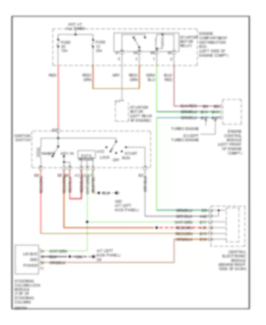
Электросхема иммобилайзера для Volvo V50 2007
Электросхема иммобилайзера для Volvo V50 2007 - Список элементов:
- (at left kick panel) g6
- A15
- A42
- Acc
- B10
- B11
- B13
- B17
- Central electronic module (behind right side of dash)
- Engine compartment distribution box (left side of engine compt)
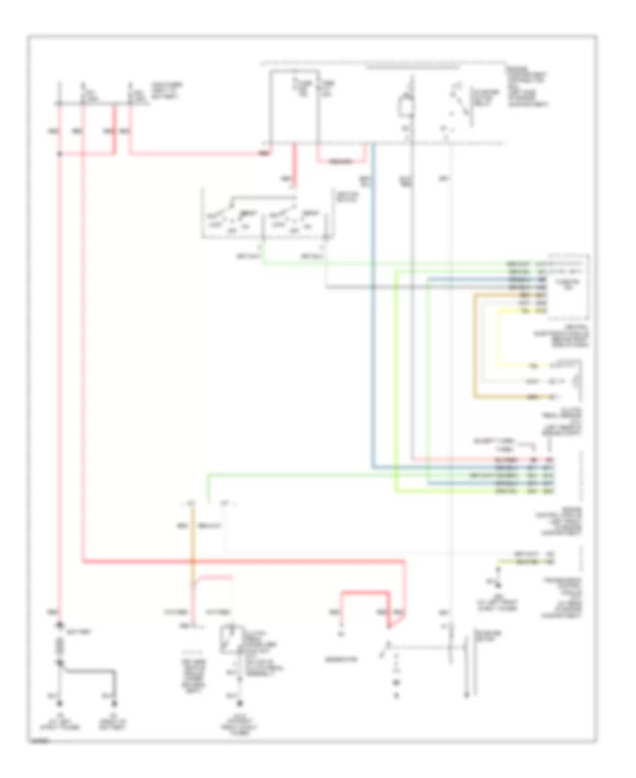
- Engine control module (left front of engine compt)
- Except turbo engine
- Fuse 15a
- Fuse 30a
- G83 (at left kick panel)
- Gnd
- Hot at all times
- Ignition switch
- Inhibit
- Key in
- Lin bus
- Lock
- Off
- Pats module
- Power
- Red
- Run
- Start
- Starter motor (left rear of engine)
- Starter motor relay
- Steering column lock module (top of steering column)
- Turbo engine
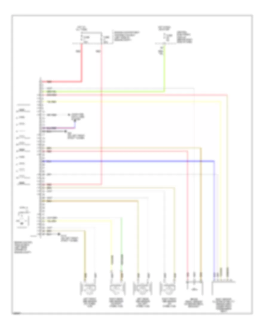
СИСТЕМА АНТИБЛОКИРОВОЧНОЙ ТОРМОЗНОЙ СИСТЕМЫ ABS
Электросхема антиблокировочной тормозной системы АБС (ABS), С Динамическое Управление Стабильностью для Volvo V50 2007
Электросхема антиблокировочной тормозной системы АБС (ABS), С Динамическое Управление Стабильностью для Volvo V50 2007 - Список элементов:
- Body sensor cluster stability sensor (bsc) (under front passenger's seat)
- Brake control module (bcm) (left rear corner of engine compt)
- Brake pedal sensor (on brake pedal bracket)
- Central electronic module (behind right side of dash)
- Computer data lines system
- Engine compartment distribution box (left side of engine compt)
- Fuse 20a
- Fuse 30a
- Fuse 5a
- G119 (on left front strut tower)
- G80 (on left front strut tower)
- Hot at all times
- Hot in run or start
- Left front abs sensor (on wheel hub)
- Left rear abs sensor (on left wheel hub)
- Red
- Right front abs sensor (on wheel hub)
- Right rear abs sensor (on right wheel hub)
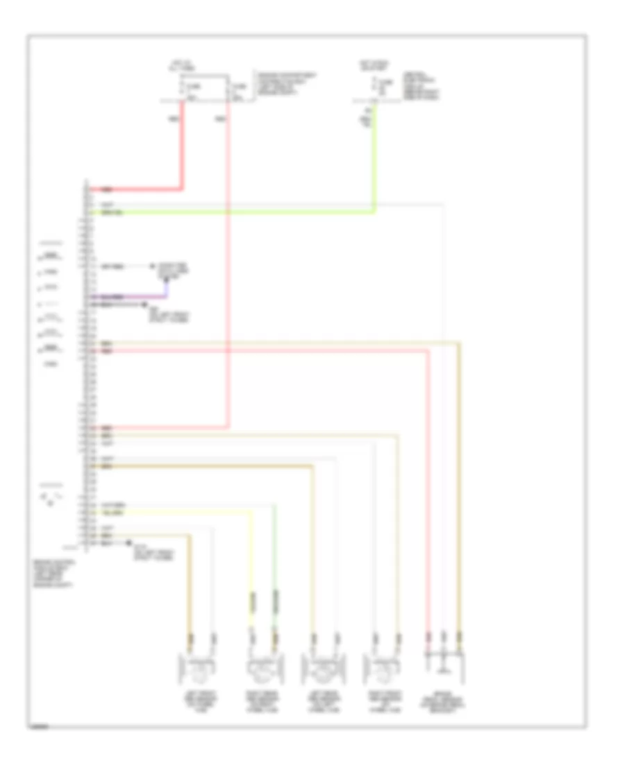
Электросхема антиблокировочной тормозной системы АБС (ABS), без Динамическое Управление Стабильностью для Volvo V50 2007
Электросхема антиблокировочной тормозной системы АБС (ABS), без Динамическое Управление Стабильностью для Volvo V50 2007 - Список элементов:
- Brake control module (bcm) (left rear corner of engine compt)
- Brake pedal sensor (on brake pedal bracket)
- Central electronic module (behind right side of dash)
- Computer data lines system
- Engine compartment distribution box (left side of engine compt)
- Fuse 20a
- Fuse 30a
- Fuse 5a
- G119 (on left front strut tower)
- G80 (on left front strut tower)
- Hot at all times
- Hot in run or start
- Left front abs sensor (on wheel hub)
- Left rear abs sensor (on left wheel hub)
- Red
- Right front abs sensor (on wheel hub)
- Right rear abs sensor (on right wheel hub)
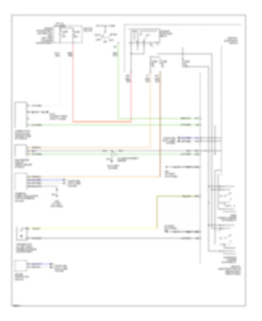
СИСТЕМА КОНДИЦИОНЕРА
Электросхема кондиционера (1 из 2) для Volvo V50 2007
Электросхема кондиционера (1 из 2) для Volvo V50 2007 - Список элементов:
- Air quality sensor (at right side of plenum)
- Climate control module (ccm)
- Climate control system relay
- Computer data lines system
- Defroster damper motor (left side of hvac housing)
- Electromagnetic clutch (climate control system) (left front of engine)
- Engine cpmpartment distribution box (left side of engine compt)
- Engine management main relay
- Evaporator temperature sensor (near center of hvac housing)
- Floor/ventilation damper motor (left side of hvac housing)
- Fuse f10 40a
- Fuse f16 40a
- Fuse f27 10a
- Fuse f3 60a
- Fuse f34 10a
- Fuse f35 15a
- Fuse f9 30a
- G10 (at right kick panel)
- G110 (on right front strut tower)
- Hot at all times
- Interior temerature sensor (center of dash)
- Left side temperature damper motor (on right side of hvac housing)
- Passenger compartment fan motor (behind center of dash)
- Recirculation damper motor (on lower right side of hvac housing)
- Red
- Right side temperature damper motor (on right side of hvac housing)
Электросхема кондиционера (2 из 2) для Volvo V50 2007
Электросхема кондиционера (2 из 2) для Volvo V50 2007 - Список элементов:
- A17
- B10
- B16
- B25
- B27
- B28
- B31
- B47
- B51
- B53
- Central electronic module (cem) (behind right side of dash)
- Climate control system pressure monitor
- Climate control system pressure sensor (at right rear of engine compt)
- Comfort functions relay
- Driver's door module
- Driver's door power rear view mirror
- Engine control module (ecm) (left front of engine compt)
- Fuse 10a
- Fuse 5a
- Infotainment relay
- Outdoor temperature sensor
- Solar twilight sensor & indicator alarm (on top center of dash)
- Turbo engine except turbo engine
Электросхема кондиционера с ручный управлением (1 из 2) для Volvo V50 2007
Электросхема кондиционера с ручный управлением (1 из 2) для Volvo V50 2007 - Список элементов:
- Climate control module (ccm)
- Climate control system relay
- Computer data lines system
- Defroster damper motor (left side of hvac housing)
- Electromagnetic clutch (climate control system) (left front of engine)
- Engine cpmpartment distribution box (left side of engine compt)
- Engine management main relay
- Evaporator temperature sensor (near center of hvac housing)
- Floor/ventilation damper motor (left side of hvac housing)
- Fuse f10 40a
- Fuse f16 40a
- Fuse f27 10a
- Fuse f3 60a
- Fuse f34 10a
- Fuse f35 15a
- Fuse f9 30a
- G10 (at right kick panel)
- G110 (on right front strut tower)
- Hot at all times
- Left side temperature damper motor (on right side of hvac housing)
- Passenger compartment fan motor (behind center of dash)
- Recirculation damper motor (on lower right side of hvac housing)
- Red
Электросхема кондиционера с ручный управлением (2 из 2) для Volvo V50 2007
Электросхема кондиционера с ручный управлением (2 из 2) для Volvo V50 2007 - Список элементов:
- A17
- B10
- B16
- B25
- B27
- B28
- B31
- B47
- B51
- B53
- Central electronic module (cem) (behind right side of dash)
- Climate control system pressure monitor
- Climate control system pressure sensor (at right rear of engine compt)
- Comfort functions relay
- Driver's door module
- Driver's door power rear view mirror
- Engine control module (ecm) (left front of engine compt)
- Fuse 10a
- Fuse 5a
- Infotainment relay
- Outdoor temperature sensor
- Solar twilight sensor & indicator alarm (on top center of dash)
- Turbo engine except turbo engine
СИСТЕМА КРУИЗКОНТРОЛЯ
Электросхема системы круизконтроля для Volvo V50 2007
Электросхема системы круизконтроля для Volvo V50 2007 - Список элементов:
- 2.4l
- 2.5l turbo
- A14
- A15
- A19
- A24
- A45
- A65
- A72
- A74
- A75
- A88
- A96
- Accelerator pedal sensor (near accelerator pedal)
- B16
- B2 nca
- B26
- B27
- B3 nca
- B41
- B45
- B5 nca
- B54
- B58
- Brake control module (at left rear corner of engine compt)
- Brake pedal sensor (at left rear corner of engine compt)
- Central electronic module (behind right side of dash)
- Central electronic module (cem) (behind right side of dash)
- Clutch pedal sensor (left rear of engine compartment)
- Computer data lines system
- Contact reel (top of steering column)
- Cruise control unit (sws)
- Engine compt distribution box (left side of engine compt)
- Engine control module (ecm) (left front of engine compt)
- Engine management system main relay
- Engine throttle body (at rear of engine)
- Fuse 10a
- Fuse 30a
- Fuse 5a
- G12
- G21
- G22
- G23
- G31
- G84 (at right kick panel)
- Hot at all times
- Hot w/ comfort functions relay energized
- Nca
- Red
- Steering wheel module (top of steering column)
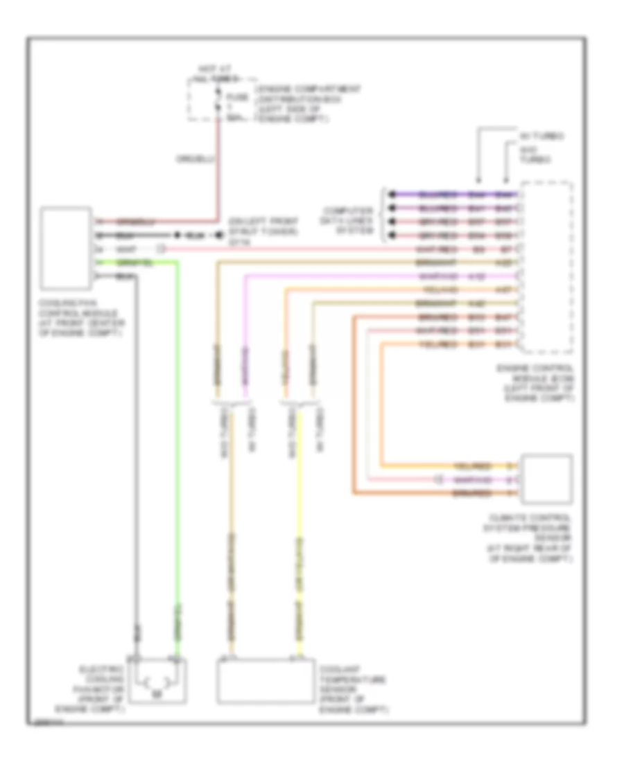
СИСТЕМА ОХЛАЖДЕНИЯ
Электросхема системы охлаждения для Volvo V50 2007
Электросхема системы охлаждения для Volvo V50 2007 - Список элементов:
- (on left front strut tower) g114
- A12
- A22
- A42
- A67
- B31
- B41
- B44
- B45
- B47
- B51
- B53
- B54
- B57
- B58
- Climate control system pressure sensor (at right rear of of engine compt)
- Computer data lines system
- Coolant temperature sensor (front of engine compt)
- Cooling fan control module (at front center of engine compt)
- Electric cooling fan motor (front of engine compt)
- Engine compartment distribution box (left side of engine compt)
- Engine control module (ecm) (left front of engine compt)
- Fuse 50a
- Hot at all times
- W/ turbo
- W/o turbo
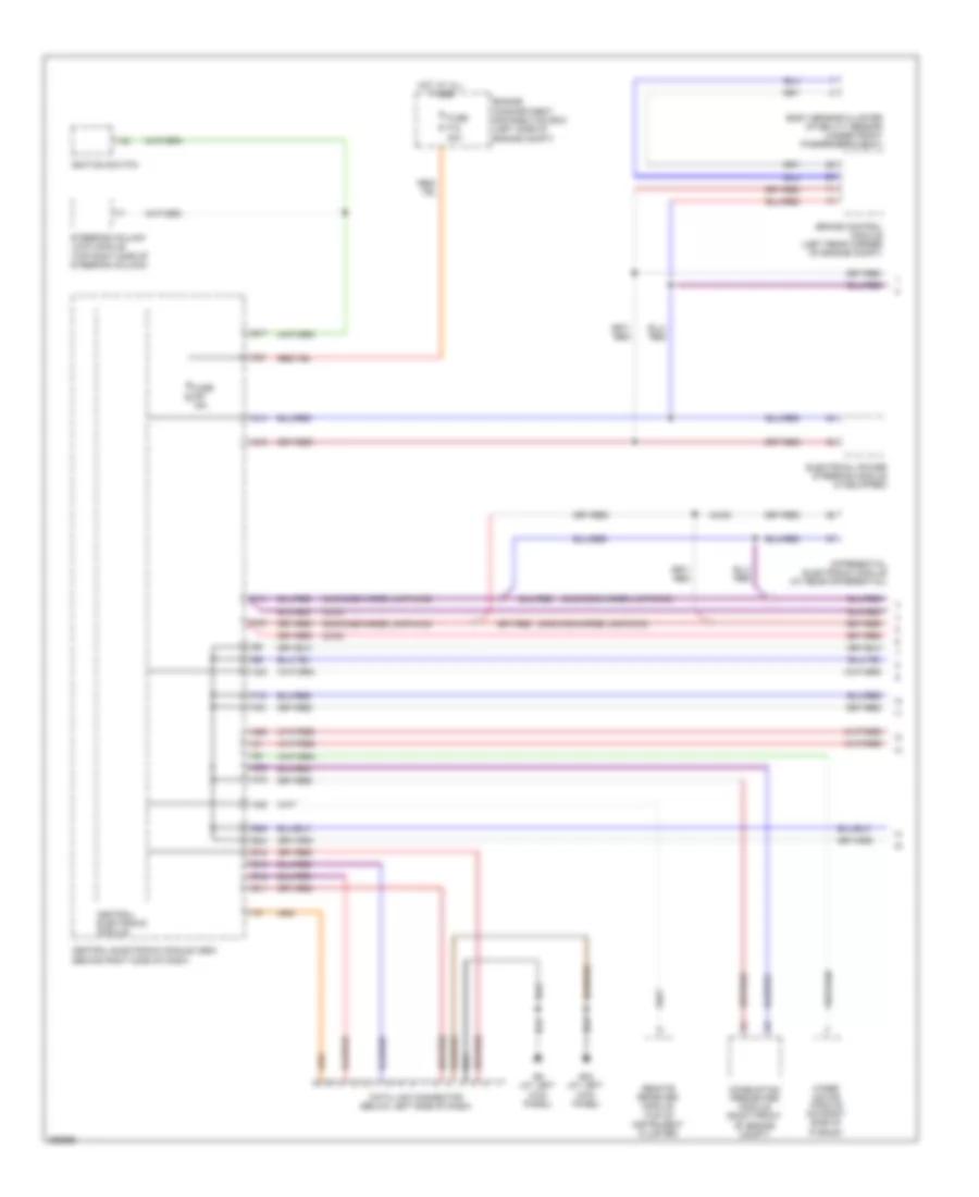
СИСТЕМА ПЕРЕДАЧИ ДАННЫХ
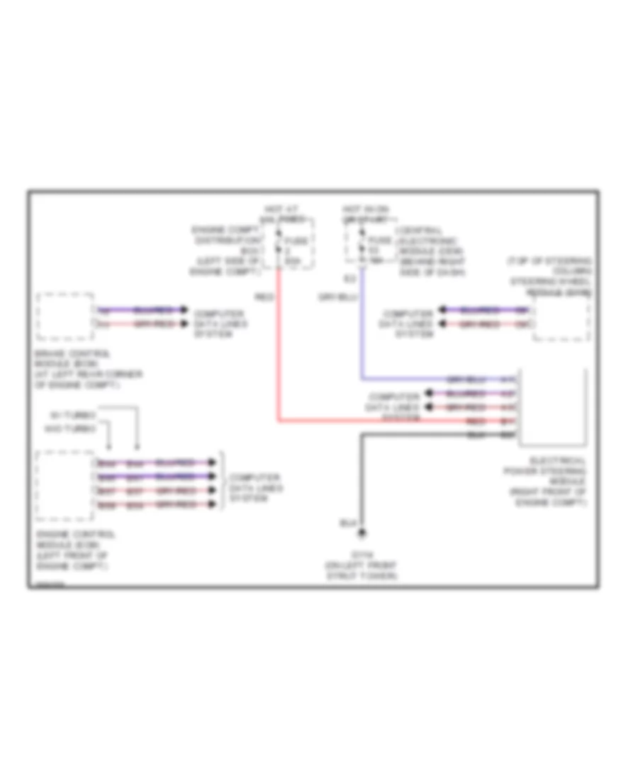
Электросхема линии передачи данных CAN (1 из 4) для Volvo V50 2007
Электросхема линии передачи данных CAN (1 из 4) для Volvo V50 2007 - Список элементов:
- (2wd)
- (4wd)
- (gas discharge lamp/2wd)
- (gas discharge lamp/4wd)
- A35
- B11
- B12
- B15
- B16
- B17
- B24
- B25
- Body sensor cluster stability sensor (under front passenger's seat)
- Brake control module (left rear corner of engine compt)
- Central electronic module
- Central electronic module (cem) (behind right side of dash)
- Combustion preheater module (right front of engine compt)
- Data link connector (below left side of dash)
- Differential electronic module (at rear differential)
- E21
- Electrical power steering module (if equipped)
- Engine compartment distribution box (left side of engine compt)
- F14
- F15
- F16
- F30
- Fuse f18 40a
- Fuse f57 15a
- G14
- G15
- G16
- G26
- G32
- G6 (at left kick panel)
- G83 (at left kick panel)
- H23
- Hot at all times
- Ignition switch
- Remote receiver module (top of instrument cluster)
- Steering column lock module (top right side of steering column)
- Wiper motor module (on right side of plenum)
Электросхема линии передачи данных CAN (2 из 4) для Volvo V50 2007
Электросхема линии передачи данных CAN (2 из 4) для Volvo V50 2007 - Список элементов:
- A10
- A11
- A12
- A13
- Accessory electronic module (right rear corner of cargo comp)
- Climate control module
- Driver information module
- Infotainment control module
- Integrated audio module
- Left gas discharge lamp master control module (behind left headlight)
- Multimedia module (if equipped)
- Parking assistance module (right rear corner of cargo comp)
- Passenger door module (in front passenger's door)
- Phone module (if equipped)
- Rain sensor module (front center of roof)
- Right camera module (right rear view mirror)
- Right gas discharge lamp master control module (behind right headlight)
- Right rear door module (in right rear door)
- Siren control module (right front wheelwell)
- To audio module (diagram 4 of 4)
- Trailer module (left rear of trunk)
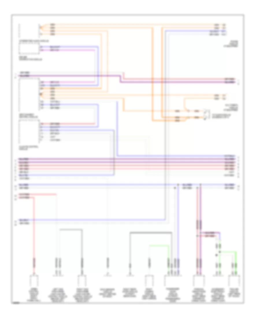
Электросхема линии передачи данных CAN (3 из 4) для Volvo V50 2007
Электросхема линии передачи данных CAN (3 из 4) для Volvo V50 2007 - Список элементов:
- (at rear of engine compt) transmission control module
- A12
- A13
- A46
- A51
- A52
- A53
- A56
- A88
- Additive dosing module (behind left rear seat)
- Alternator
- Automatic transmission program selector
- B41
- B44
- B45
- B54
- B57
- B58
- Climate control system
- Driver's door module (in driver's door)
- Driver's door power window switch
- Driver's power seat module
- Driver's side seat heating module (under driver's seat)
- Engine control module (left side of engine compt)
- Except turbo engine
- Gear selector module (at base of shift lever assembly)
- Keyless vehicle module (under driver's seat)
- Left camera module (left rear view mirror)
- Left rear door module (in left rear door)
- Occupant weight sensor (in front passenger's seat)
- Passenger's side seat heating module (under passenger's seat)
- Red
- Steering wheel module
- Turbo engine
Электросхема линии передачи данных CAN (4 из 4) для Volvo V50 2007
Электросхема линии передачи данных CAN (4 из 4) для Volvo V50 2007 - Список элементов:
- Audio module (left side of trunk)
- From integrated audio module (diagram 2 0f 4)
- Global positioning system module (left side of trunk)
- Remote digital audio receiver (left rear of trunk)
- Traffic message channel module (s40: behind rear seat) (v50: at right "c" pillar)
- W/ premium audio system
- W/ premium audio system & gps
- W/ premium audio system & remote digital audio receiver
- W/ premium audio system, gps & remote digital audio receiver
- W/ premium audio system, gps & traffic message channel
СИСТЕМА УПРАВЛЕНИЯ ДВИГАТЕЛЯ
2.4L
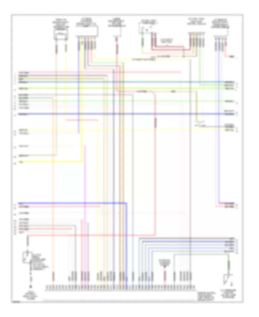
2.4L, Электросхема системы управления двигателем (1 из 4) для Volvo V50 2007
2.4L, Электросхема системы управления двигателем (1 из 4) для Volvo V50 2007 - Список элементов:
- (at left front of engine compt) vacuum pump
- (left rear of engine compt) vacuum pump switch
- A10
- A11
- A12
- A13
- A14
- A15
- A16
- A17
- A18
- A19
- A20
- A21
- A22
- A23
- A24
- A25
- A26
- A27
- A28
- A29
- A30
- A31
- A32
- A33
- A34
- A35
- A36
- A37
- A38
- A39
- A40
- A41
- A42
- A43
- A44
- A45
- A46
- A47
- A48
- A49
- A50
- Camshaft position sensor (exhaust side) (right rear of engine)
- Center heated oxygen sensor (center of catalytic converter)
- Engine compartment distribution box (left side of engine compt)
- Engine control module (ecm) (left front of engine compt)
- Engine management system main relay
- Front heated oxygen sensor (upstream of catalytic converter)
- Front knock sensor (on left side of engine)
- Fuse f32 10a
- Fuse f33 20a
- Fuse f34 10a
- Fuse f35 15a
- Fuse f36 10a
- Fuse f9 5a
- G114 (on left front strut tower)
- Hot at all times
- Nca
- Rear heated oxygen sensor (downstream of catalytic converter)
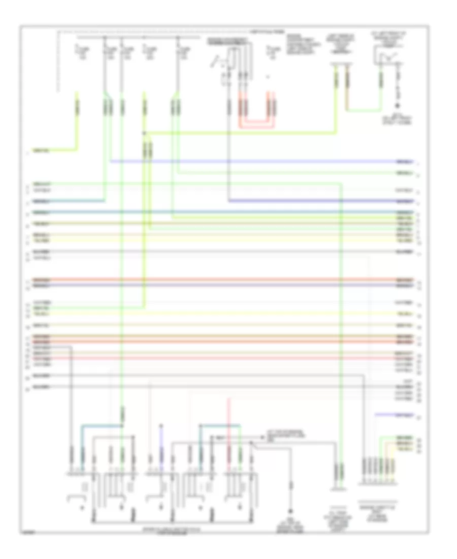
2.4L, Электросхема системы управления двигателем (2 из 4) для Volvo V50 2007
2.4L, Электросхема системы управления двигателем (2 из 4) для Volvo V50 2007 - Список элементов:
- (at right rear of engine) evap valve
- (at top of engine, near spark plugs) g89
- (left front of engine) fuel pressure & temperature sensor
- (on left rear of engine) intake manifold pressure sensor
- (on top front of engine) variable valve timing intake solenoid
- (on top rear of engine, in air duct) mass airflow (maf) sensor
- (right rear of engine) camshaft position sensor (intake side)
- G88 (at top of engine, near spark plugs)
- Impulse sensor (on top rear of engine)
- Nca
- Oil trap ptc resistor (left side of engine compt)
- Spark plugs & ignition coils (top of engine)
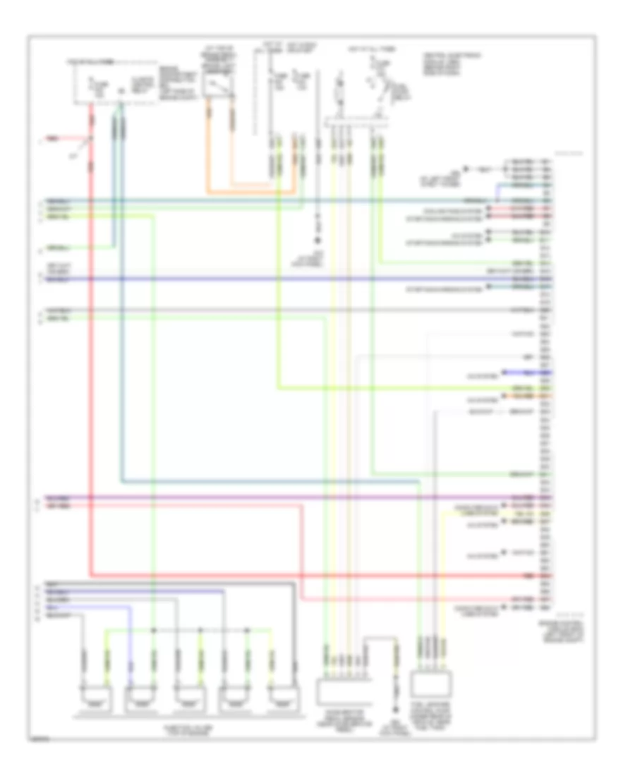
2.4L, Электросхема системы управления двигателем (3 из 4) для Volvo V50 2007
2.4L, Электросхема системы управления двигателем (3 из 4) для Volvo V50 2007 - Список элементов:
- (at fuel tank) fuel pump control module
- (at rear of engine compt) transmission control module
- (at rear of engine) engine throttle body
- (front of engine compt) coolant temperature sensor
- (in fuel tank) fuel pump
- (under driver's seat) keyless vehicle module
- A/t
- A51
- A52
- A53
- A54
- A55
- A56
- A57
- A58
- A59
- A60
- A61
- A62
- A63
- A64
- A65
- A66
- A67
- A68
- A69
- A70
- A71
- A72
- A73
- A74
- A75
- A76
- A77
- A78
- A79
- A80
- A81
- A82
- A83
- A84
- A85
- A86
- A87
- A88
- A89
- A90
- A91
- A92
- A93
- A94
- A95
- A96
- A97
- B20
- Clutch pedal immobilizer contact (on top of clutch pedal assembly)
- Engine control module (ecm) (left front of engine compt)
- G110 (on right front strut tower)
- G116 (at right kick panel)
- M/t
- Oil pressure monitor (on left side of engine)
- Red
- Starting/ charging system
- W/ plastic gas tank
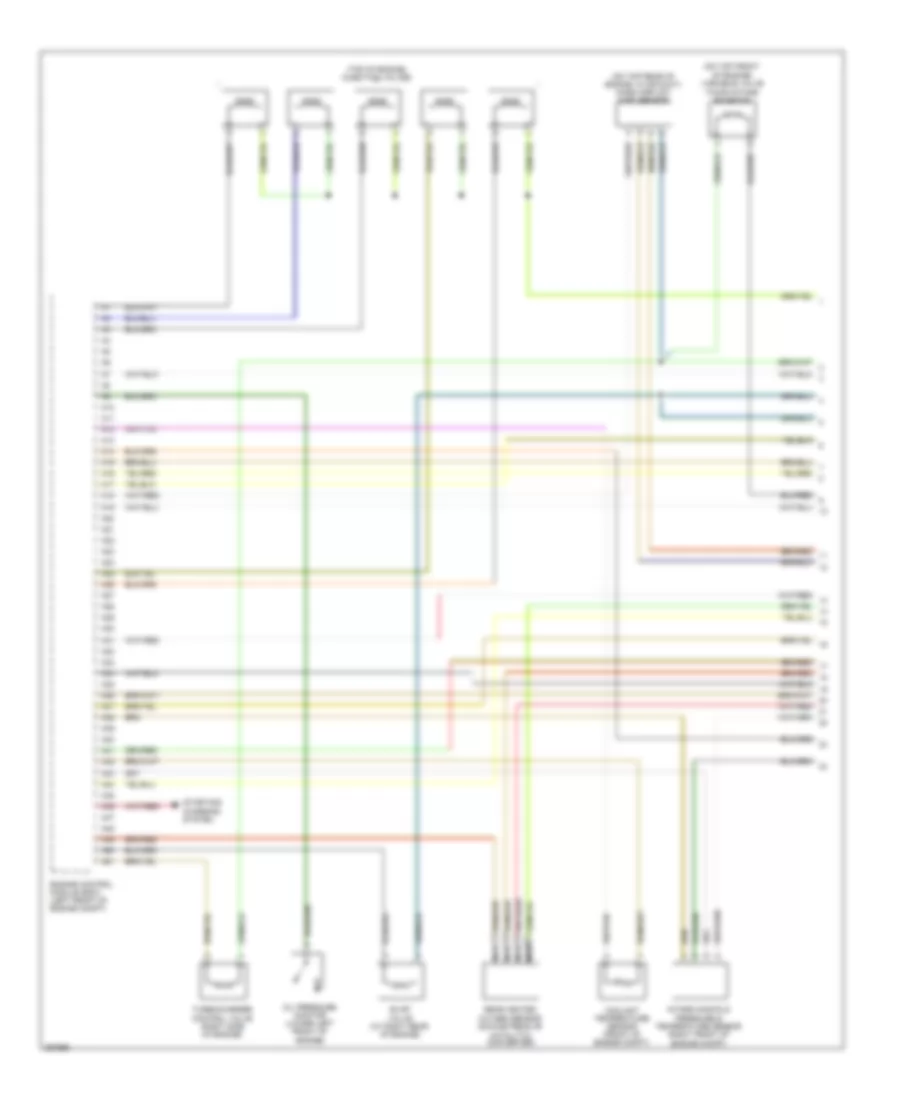
2.4L, Электросхема системы управления двигателем (4 из 4) для Volvo V50 2007
2.4L, Электросхема системы управления двигателем (4 из 4) для Volvo V50 2007 - Список элементов:
- (at top of brake pedal assembly) brake light contact
- A/c system
- A/t
- A28
- Accelerator pedal sensor (near accelerator pedal)
- All times
- B10
- B11
- B12
- B13
- B14
- B15
- B16
- B17
- B18
- B19
- B20
- B21
- B22
- B23
- B24
- B25
- B26
- B27
- B28
- B29
- B30
- B31
- B32
- B33
- B34
- B35
- B36
- B37
- B38
- B39
- B40
- B41
- B42
- B43
- B44
- B45
- B46
- B47
- B48
- B49
- B50
- B51
- B52
- B53
- B54
- B55
- B56
- B57
- B58
- C16
- Central electronic module (cem) (behind right side of dash)
- Climate control relay
- Computer data lines system
- Cooling fans system
- E10
- E28
- E40
- E41
- Engine compartment distribution box (left side of engine compt)
- Engine control module (ecm) (left front of engine compt)
- Fuel leakage control pump (under rear of vehicle, near fuel tank)
- Fuel pump relay
- Fuse f23 10a
- Fuse f54 10a
- Fuse f57 15a
- Fuse f74 15a
- G10 (at right kick panel)
- G22
- G31
- G52 (at left front strut tower)
- G84 (at right kick panel)
- Hot at all times
- Hot at hot in run or start
- Injection valves (top of engine)
- Red
- Starting/charging system
2.5L ТУРБО
2.5L турбо, Электросхема системы управления двигателем (1 из 4) для Volvo V50 2007
2.5L турбо, Электросхема системы управления двигателем (1 из 4) для Volvo V50 2007 - Список элементов:
- (on top front of engine) variable valve timing intake solenoid
- (on top rear of engine, in air duct) mass airflow (maf) sensor
- (top of engine) injection valves
- A10
- A11
- A12
- A13
- A14
- A15
- A16
- A17
- A18
- A19
- A20
- A21
- A22
- A23
- A24
- A25
- A26
- A27
- A28
- A29
- A30
- A31
- A32
- A33
- A34
- A35
- A36
- A37
- A38
- A39
- A40
- A41
- A42
- A43
- A44
- A45
- A46
- A47
- A48
- A49
- A50
- A51
- Coolant temperature sensor (front of engine compt)
- Engine control module (ecm) (left front of engine compt)
- Evap valve (at right rear of engine)
- Intake manifold pressure & temperature sensor (right front of engine compt)
- Nca
- Oil pressure monitor (lower left front of engine)
- Rear heated oxygen sensor (downstream of catalytic converter)
- Starting/ charging system
- Turbocharger control valve (right side of engine)
2.5L турбо, Электросхема системы управления двигателем (2 из 4) для Volvo V50 2007
2.5L турбо, Электросхема системы управления двигателем (2 из 4) для Volvo V50 2007 - Список элементов:
- (at left front of engine compt) vacuum pump
- (at top of engine, near spark plugs) g89
- (left rear of engine compt) vacuum pump switch
- Engine compartment distribution box (left side of engine compt)
- Engine management system main relay
- Engine throttle body (at rear of engine)
- Fuse f32 10a
- Fuse f33 20a
- Fuse f34 10a
- Fuse f35 15a
- Fuse f36 10a
- Fuse f9 5a
- G114 (on left front strut tower)
- G88 (at top of engine, near spark plugs)
- Hot at all times
- Nca
- Oil trap ptc resistor (left side of engine compt)
- Spark plugs & ignition coils (top of engine)
2.5L турбо, Электросхема системы управления двигателем (3 из 4) для Volvo V50 2007
2.5L турбо, Электросхема системы управления двигателем (3 из 4) для Volvo V50 2007 - Список элементов:
- (at fuel tank) fuel pump control module
- (at rear of engine compt) transmission control module
- (in fuel tank) fuel pump
- (left front of engine) fuel pressure & temperature sensor
- (left side of engine) front knock sensor
- (right rear of engine) camshaft position sensor (exhaust side)
- (right rear of engine) camshaft position sensor (intake side)
- A52
- A53
- A54
- A55
- A56
- A57
- A58
- A59
- A60
- A61
- A62
- A63
- A64
- A65
- A66
- A67
- A68
- A69
- A70
- A71
- A72
- A73
- A74
- A75
- A76
- A77
- A78
- A79
- A80
- A81
- A82
- A83
- A84
- A85
- A86
- A87
- A88
- A89
- A90
- A91
- A92
- A93
- A94
- A95
- A96
- A97
- Engine control module (ecm) (left front of engine compt)
- G116 (at right kick panel)
- Impulse sensor (on top rear of engine)
- Red
- W/ plastic fuel tank
2.5L турбо, Электросхема системы управления двигателем (4 из 4) для Volvo V50 2007
2.5L турбо, Электросхема системы управления двигателем (4 из 4) для Volvo V50 2007 - Список элементов:
- (at left front strut tower)
- (at right kick panel) g10
- (at top of brake pedal assembly) brake light contact
- A/c system
- A/c system computer data lines system
- A/t
- A28
- Accelerator pedal sensor (near accelerator pedal)
- B10
- B11
- B12
- B13
- B14
- B15
- B16
- B17
- B18
- B19
- B20
- B21
- B22
- B23
- B24
- B25
- B26
- B27
- B28
- B29
- B30
- B31
- B32
- B33
- B34
- B35
- B36
- B37
- B38
- B39
- B40
- B41
- B42
- B43
- B44
- B45
- B46
- B47
- B48
- B49
- B50
- B51
- B52
- B53
- B54
- B55
- B56
- B57
- B58
- C16
- Central electronic module (cem) (behind right side of dash)
- Climate control relay
- Clutch pedal immobilizer contact (on top of clutch pedal assembly)
- Computer data lines system
- Cooling fans system
- E10
- E28
- E40
- E41
- Engine compartment distribution box (left side of engine compt)
- Engine control module (ecm) (left front of engine compt)
- Front heated oxygen sensor (upstream of catalytic converter)
- Fuel leakage control pump (under rear of vehicle, near fuel tank)
- Fuel pump relay
- Fuse f23 10a
- Fuse f54 10a
- Fuse f57 15a
- Fuse f74 15a
- G110 (on right front strut tower)
- G22
- G31
- G52
- G84 (at right kick panel)
- Hot at all times
- Hot in run or start
- Keyless vehicle module (under driver's seat)
- M/t
- Nca
- Red
- Starting/charging system
- Variable valve timing outlet solenoid (on top right of engine)
СИСТЕМА УСИЛИТЕЛЯ РУЛЯ
Электросхема усилителя руля для Volvo V50 2007
Электросхема усилителя руля для Volvo V50 2007 - Список элементов:
- (top of steering column) steering wheel module (swm)
- B41
- B44
- B45
- B54
- B57
- B58
- Brake control module (bcm) (at left rear corner of engine compt)
- Central electronic module (cem) (behind right side of dash)
- Computer data lines system
- Electrical power steering module (right front of engine compt)
- Engine compt distribution box (left side of engine compt)
- Engine control module (ecm) (left front of engine compt)
- Fuse 10a
- Fuse 80a
- G114 (on left front strut tower)
- Hot at all times
- Hot in on or start
- Red
- W/ turbo
- W/o turbo
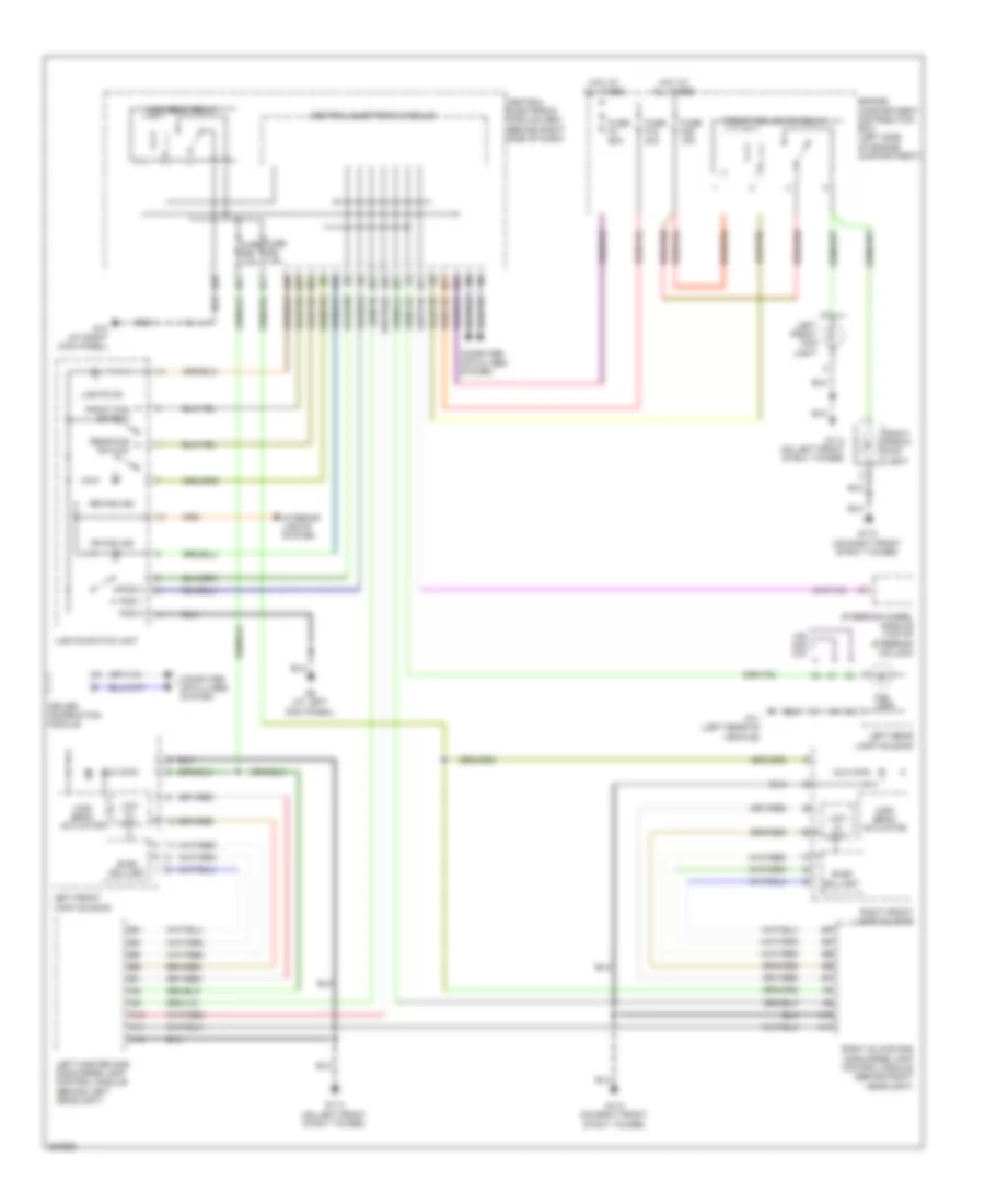
Система Фар
Электросхема фар, С ксеноновые лампы для Volvo V50 2007
Электросхема фар, С ксеноновые лампы для Volvo V50 2007 - Список элементов:
- A10
- A11
- A12
- A28
- A32
- A40
- Aux main
- B22
- B23
- B31
- Central electronic module
- Central electronic module (cem) (behind right side of dash)
- Computer data lines system
- Driver information module
- E11
- E21
- E22
- E25
- E27
- E37
- Elec ballast
- Engine compartment distribution box (left side of engine compartment)
- Fog lamp
- Fr fog ind
- Front fog lights relay
- Front fog switch
- Fuse f18 40a
- Fuse f29 15a
- Fuse f4 60a
- Fuse f58 7.5a
- Fuse f59 7.5a
- G10 (at right kick panel)
- G11 (left rear of vehicle)
- G110 (on right front strut tower)
- G114 (on left front strut tower)
- G26
- G6 (at left kick panel)
- High beam actuator
- High beam relay
- Hot at all times
- Interior lights system
- Left front fog light
- Left front lamp housing
- Left master gas discharge lamp control module (behind left headlight)
- Left rear lamp housing
- Lights on
- Lights switch unit
- Low mi vdrtl
- Pos 0
- Pos 1
- Pos 2
- Rear fog switch
- Right front fog light
- Right front lamp housing
- Right slave gas discharge lamp control module (behind right headlight)
- Rr fog ind
- Steering wheel module (top of steering column)
- V50 s40 c70
Электросхема фар, без Ксеноновые лампы для Volvo V50 2007
Электросхема фар, без Ксеноновые лампы для Volvo V50 2007 - Список элементов:
- (c70)
- (s40)
- (s40, v50)
- (v50)
- A28
- A32
- B22
- B23
- B31
- C4 c1
- Central electronic module
- Central electronic module (behind right side of dash)
- Computer data lines system
- Driver information module
- E11
- E21
- E22
- E25
- E27
- E37
- Engine compartment distribution box (left side of engine compartment)
- Fog lamp
- Fr fog ind
- Front fog lights relay
- Front fog switch
- Fuse f18 40a
- Fuse f29 15a
- Fuse f4 60a
- Fuse f58 7.5a
- Fuse f59 7.5a
- G10 (at right kick panel)
- G11 (left rear of vehicle)
- G110 (on right front strut tower)
- G114 (on left front strut tower)
- G6 (at left kick panel)
- High
- High beam relay r8
- Hot at all times
- Interior lights system
- Left front fog light
- Left front lamp housing
- Left rear lamp housing
- Lights switch unit
- Low
- Pos 0
- Pos 1
- Pos 2
- Rear fog switch
- Right front fog light
- Right front lamp housing
- Rr fog ind
- Steering wheel module (top of steering column)
Электросхема корректора фар для Volvo V50 2007
Электросхема корректора фар для Volvo V50 2007 - Список элементов:
- A10
- A11
- A12
- Central electronic module (cem)
- Central electronic module (cem) (behind right side of dash)
- E11
- E21
- E22
- E27
- E29
- Elec ballast
- Engine compartment distribution box (left side of engine compartment)
- Front angle sensor (in left front wheelwell)
- Fuse f18 40a
- Fuse f4 60a
- Fuse f51 10a
- Fuse f58 7.5a
- Fuse f59 7.5a
- G110 (on right front strut tower)
- G114 (on left front strut tower)
- G26
- High beam actuator
- High beam relay r8
- Hot at all times
- Hot in on or start
- Left front lamp housing
- Left master gas discharge lamp control module (behind left headlight)
- Leveling
- Low mi vdrtl
- Rear angle sensor (in left rear wheelwell)
- Right front lamp housing
- Right slave gas discharge lamp control module (behind right headlight)
СИСТЕМЫ ПАМЯТИ
Электросхема памяти водительского сиденья для Volvo V50 2007
Электросхема памяти водительского сиденья для Volvo V50 2007 - Список элементов:
- (under driver's seat)
- 30p
- 31p
- 31s
- B10
- B11
- B12
- B13
- B14
- C20
- C30
- Can+
- Can-
- Cem
- Central electronic module (cem) (behind right side of dash)
- Computer data lines system
- Driver's seat backrest angle motor
- Driver's seat fore/aft motor
- Driver's seat up/down front edge motor
- Driver's seat up/down rear edge motor
- Ext-x
- F15
- F30
- Fuse 25a
- Fuse 86 5a
- G66 (below driver's seat, near rocker panel)
- Hot at all times
- Hsg
- Hss
- Interior lighting relay
- Power seat module (psm)
СИСТЕМЫ СИДЕНИЙ
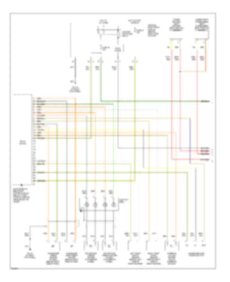
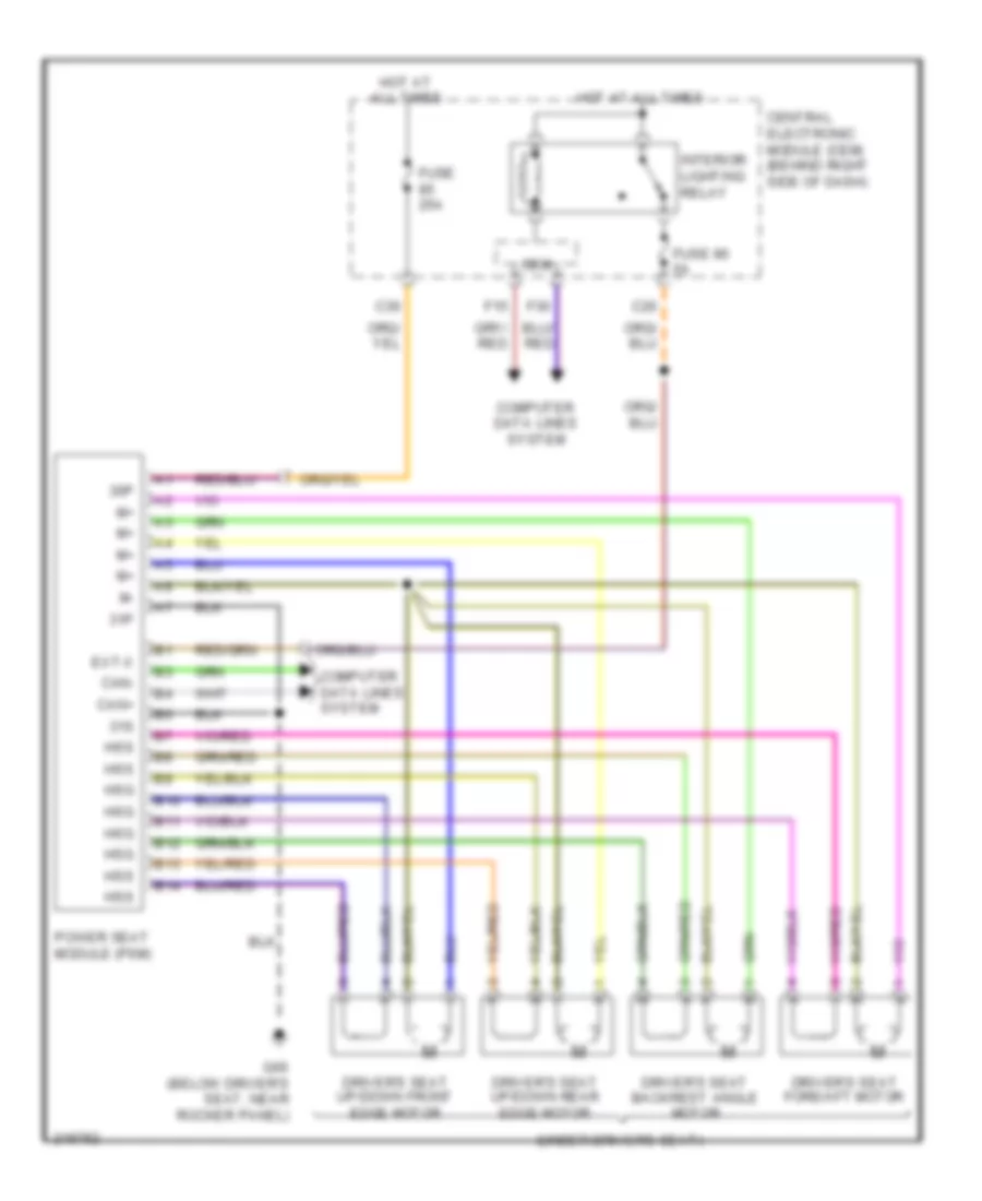
Электросхема привода водительского сиденья для Volvo V50 2007
Электросхема привода водительского сиденья для Volvo V50 2007 - Список элементов:
- 30p
- Back
- Backrest switch
- C20
- C30
- Central electronic module
- Central electronic module (behind right side of dash)
- Down
- Driver's seat backrest angle motor (under driver's seat)
- Driver's seat fore/aft motor (under driver's seat)
- Driver's seat front edge up/down motor (under driver's seat)
- Driver's seat rear edge up/down motor (under driver's seat)
- E20
- E21
- Engine compartment distribution box (left side of engine compt)
- Ext x
- Forw
- Front edge up/down switch
- Fuse 25a
- Fuse 40a
- Fuse 5a
- Fuse 60a
- Fwd/back switch
- G66 (below driver's seat, on rocker panel)
- Hot at all times
- Interior lighting relay
- Memory
- Power driver's seat switch unit
- Rear edge up/down switch
- Stop logic
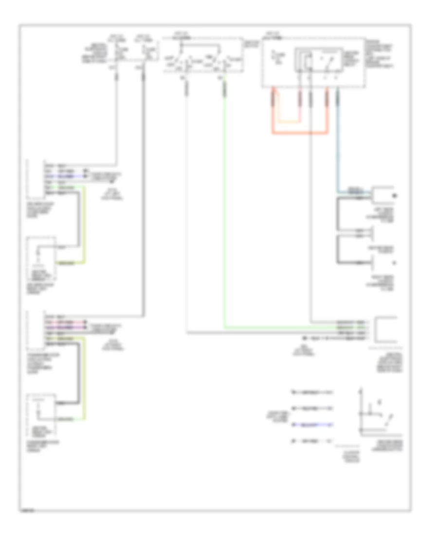
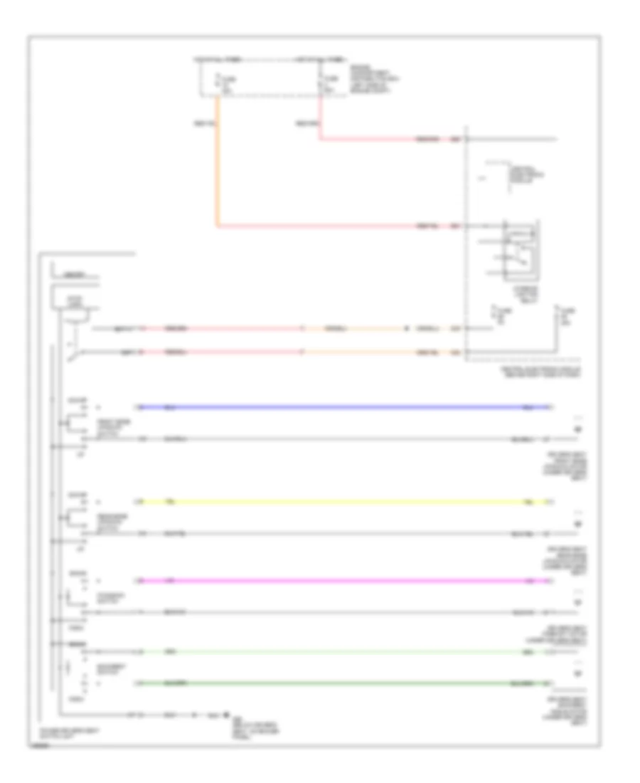
Электросхема подогрева сидений для Volvo V50 2007
Электросхема подогрева сидений для Volvo V50 2007 - Список элементов:
- B41
- B45
- B54
- B58
- C42
- C43
- Central
- Central electronic module (behind right side of dash)
- Climate control module (ccm)
- Comfort functions relay
- Computer data lines system
- Driver's seat backrest heating coil
- Driver's seat cushion heating coil
- Driver's seat temperature sensor (in driver front seat cushion)
- Driver's side seat heater module (under driver's seat)
- E20
- Electronic module
- Engine compartment distribution box (left side of engine compartment)
- Engine control module (left front of engine compartment)
- Fuse 15a
- Fuse 60a
- G66 (below driver's seat, near rocker panel)
- G67 (below passenger's seat, near rocker panel)
- Hot at all times
- Passenger's seat backrest heater
- Passenger's seat cushion heating coil
- Passenger's seat temperature sensor (in passenger front seat cushion)
- Passenger's side seat heater module (under front passenger's seat)
- Red
- W/ turbo
- W/o turbo
Электросхема привода пассажирского сиденья для Volvo V50 2007
Электросхема привода пассажирского сиденья для Volvo V50 2007 - Список элементов:
- 30p
- Back
- Backrest switch
- C20
- C29
- Central electronic module
- Central electronic module (behind right side of dash)
- Down
- E20
- E21
- Engine compartment distribution box (left side of engine compt)
- Ext.x
- Forw
- Front edge up/down switch
- Fuse 25a
- Fuse 40a
- Fuse 5a
- Fuse 60a
- Fwd/back switch
- G67 (below passenger's seat, near rocker panel)
- Hot at all times
- Interior lighting relay
- Passenger's seat backrest angle motor (under front passenger's seat)
- Passenger's seat fore/aft motor (under front passenger's seat)
- Passenger's seat front edge up/down motor (under front passenger's seat)
- Passenger's seat rear edge up/down motor (under front passenger's seat)
- Power passenger seat switch unit
- Rear edge up/down switch
- Stop logic
Стартер Генератор
Электросхема Генератора для Volvo V50 2007
Электросхема Генератора для Volvo V50 2007 - Список элементов:
- 150a
- A88
- B46
- Battery
- Engine control module (2.4l) (left front of engine compartment)
- Engine control module (2.5l turbo) (left front of engine compartment)
- G3 (at left strut tower)
- G4 (front of battery)
- Generator
- Main fuses (next to battery)
- Pf1
- Red
- Starter motor
Электросхема стартера для Volvo V50 2007
Электросхема стартера для Volvo V50 2007 - Список элементов:
- A/t
- A17
- A42
- Acc
- B11
- B13
- B15
- B17
- B20
- B30
- Battery
- Central electronic module (behind right side of dash)
- Clutch pedal immobilizer contact (m/t) (on top of clutch pedal assembly)
- Clutch pedal sensor (m/t) (left rear of engine compt)
- Engine compartment distribution box (left side of engine compartment)
- Engine control module (left front of engine compartment)
- Except turbo
- Fuse f13 30a
- Fuse f26 15a
- Fuse f54 15a
- G110 (on right front strut tower)
- G12
- G21
- G23
- G3 (at left strut tower)
- G4 (front of battery)
- G52 (at left front strut tower)
- Generator
- Ignition switch
- Keyless vehicle module (under driver's seat)
- Lock
- M/t
- Main fuses (next to battery)
- Off
- Pf1 150a
- Pf2 150a
- Red
- Start
- Starter motor
- Starter motor relay
- Transmission control module (a/t) (at rear of engine compartment)
- Turbo
Стеклоочистители и Стеклоомыватели Дворники
Электросхема передних стеклоочистителей дворников и омывателя лобового стекла для Volvo V50 2007
Электросхема передних стеклоочистителей дворников и омывателя лобового стекла для Volvo V50 2007 - Список элементов:
- (at right kick panel) g10
- A14
- A17
- A28
- A45
- Acc
- Anti-theft system
- Central electronic module
- Central electronic module (behind right side of dash)
- Comfort functions relay
- Computer data lines system
- D10
- Driver information module
- E12
- E20
- Engine compartment distribution box (left side of engine compartment)
- F14
- F16
- Fuse 15a
- Fuse 30a
- Fuse 5a
- Fuse 60a
- G110 (on right front strut tower)
- G83 (at left kick panel)
- G84 (at right kick panel)
- H23
- Hot at all times
- Ignition switch
- Lock
- Off
- Rain sensor module (front center of roof)
- Rear window washer motor relay
- Run
- Start
- Steering wheel module (swm) (top of steering column)
- W/ mass movement sensor
- Washer pump (at left front corner of engine compartment)
- Windshield washer motor relay
- Wiper motor module (wmm) (on right side of plenum)
схема шайбы фары для Volvo V50 2007
схема шайбы фары для Volvo V50 2007 - Список элементов:
- A40
- Central electronic module (behind right side of dash)
- Engine compartment distribution fuse box (left side of engine compartment)
- Fuse 20a
- G11
- G110 (on right front strut tower)
- G6 (at left kick panel)
- Headlight washer motor relay
- High pressure headlight washer pump (left front corner of engine compartment)
- Hot at all times
- Light switch module
- Pos 0
- Pos 1
- Pos 2
Электросхема заднего стеклоочистителя дворника и омывателя для Volvo V50 2007
Электросхема заднего стеклоочистителя дворника и омывателя для Volvo V50 2007 - Список элементов:
- A17
- A28
- A45
- Acc
- C33
- C34
- Central electronic module
- Central electronic module (behind right side of dash)
- Comfort functions relay
- Computer data lines system
- E12
- E20
- Engine compartment distribution box (left side of engine compartment)
- F14
- F16
- Fuse 15a
- Fuse 5a
- Fuse 60a
- G10 (at right kick panel)
- G66 (below driver's seat, near rocker panel)
- G83 (at left kick panel)
- Hot at all times
- Ignition switch
- Lock
- Off
- Rear window washer motor relay
- Rear window wiper motor (at center of tailgate)
- Rear window wiper relay
- Run
- Start
- Steering wheel module (top of steering column)
- Washer pump (at left corner of engine compartment)
- Windshield washer motor relay
ЦЕНТРАЛЬНЫЙ ЗАМОК
центральная схема захвата (1 из 2) для Volvo V50 2007
центральная схема захвата (1 из 2) для Volvo V50 2007 - Список элементов:
- (at right kick panel) g116
- (below passenger's seat near rocker panel) g67
- (in right rear door) right rear door module
- A10
- A11
- A12
- A13
- A15
- A16
- A18
- Ajar sw
- Computer data lines system
- Engine compartment distribution box (left side of engine compt)
- Fuse 40a
- Fuse 60a
- Hot at all times
- Lock
- Passenger door central locking switch
- Passenger door power window switch
- Passenger's door lock unit (at rear of right front door)
- Passenger's door module (in front passenger's door)
- Right rear door lock unit (at rear of right rear door)
- Un lock
- Unl
центральная схема захвата (2 из 2) для Volvo V50 2007
центральная схема захвата (2 из 2) для Volvo V50 2007 - Список элементов:
- (at left kick panel) g115
- (behind carpet)
- (below driver's seat near rocker panel) g66
- A10
- A11
- A12
- A13
- A14
- A15
- A16
- A18
- Ajar sw
- Central electronic module (behind right side of dash)
- Computer data lines system
- Driver's door central locking switch
- Driver's door lock unit (at rear of left front door)
- Driver's door module (in driver's door)
- Flap lock
- Fuel
- Fuel filler
- Fuse 20a
- Fuse 25a
- G10 (at right kick panel)
- G12 (right rear of vehicle)
- G6 (at left kick panel)
- G66 (below driver's seat near rocker panel)
- G83 (at left kick panel)
- G84 (at right kick panel)
- Interior lights system
- Left rear door lock unit (at rear of left rear door)
- Left rear door module (in left rear door)
- Lid
- Lights switch
- Lock
- Motor
- Private lock
- Remote receiver module (rrx) (behind left side of dash)
- Switch
- Tailgate
- Trunk lid/
- Trunk lid/ tailgate lock unit (center rear of trunk)
- Trunk/tailgate handle switch
- Un lock
- Unit
- Unl
Электросхема системы безключевого доступа (1 из 2) для Volvo V50 2007
Электросхема системы безключевого доступа (1 из 2) для Volvo V50 2007 - Список элементов:
- (behind right side of dash) central electronic module
- (below passenger's seat near rocker panel) g67
- (m/t)
- A11
- A15
- B10
- B11
- B12
- B13
- B14
- B15
- B16
- B17
- B18
- B19
- B20
- C26
- C32
- C41
- Clutch pedal immobilizer switch (at top of clutch pedal assembly)
- Clutch switch
- Computer data lines system
- D10
- D11
- D12
- D13
- D14
- D15
- D16
- D17
- D18
- D19
- D20
- D21
- D22
- D23
- Driver front door lock antenna
- E21
- E22
- Engine compartment distribution box (left side of engine compt)
- Fuse 15a
- Fuse 40a
- Fuse 60a
- Fuse f55 20a
- G110 (in right front strut tower)
- G66 (below driver's seat near rocker panel)
- Hot at all times
- Ignition switch
- Key in
- Keyless vehicle module (under driver's seat)
- Keyless vehicle signal receiver (rke) (top of instrument cluster)
- Left rear door lock unit (at rear of left rear door)
- Left rear front door lock antenna
- License plate lighting
- Passenger door contact locking
- Passenger door lock module
- Passenger front door lock antenna
- Red
- Release motor
- Right rear door contact locking
- Right rear front door lock antenna
Электросхема системы безключевого доступа (2 из 2) для Volvo V50 2007
Электросхема системы безключевого доступа (2 из 2) для Volvo V50 2007 - Список элементов:
- (below driver's seat near rocker panel) g66
- (below passenger's seat near rocker panel) g67
- A10
- A11
- A12
- A13
- A14
- A15
- A16
- A17
- A18
- A19
- A20
- A21
- A22
- A23
- A24
- Bumper compartment door lock antenna (behind center of rear bumper)
- Cabin 1 rear door lock antenna (behind rear seat)
- Cabin 2 door lock antenna (under center console)
- Cabin 3 door lock antenna (under center console)
- Clutch switch
- Driver door contact locking
- Driver door lock module
- Driver's door lock unit (at rear of left front door)
- E10
- E11
- E12
- E13
- E14
- E15
- E16
- E17
- E18
- E19
- E20
- E21
- E22
- Keyless vehicle module (under driver's seat)
- Left rear door contact locking
- Passenger's door lock unit (at rear of right front door)
- Release motor
- Right rear door lock unit (at rear of right rear door)

 Čeština
 Dansk
Dansk Deutsch
 Ελληνικά
 English
 English
 Español
 Suomi
Suomi Français
 Français
 עברית
עברית Hrvatski
 Magyar
 Italiano
 日本語
日本語 한국어
한국어 Polski
 Português
 Português
 Română
 Русский
 Slovenčina
 Slovenščina
 Svenska
 Türkçe
 中文 (中国)