ANTI-LOCK BRAKES
Anti-lock Brakes Wiring Diagram for Infiniti QX4 2003
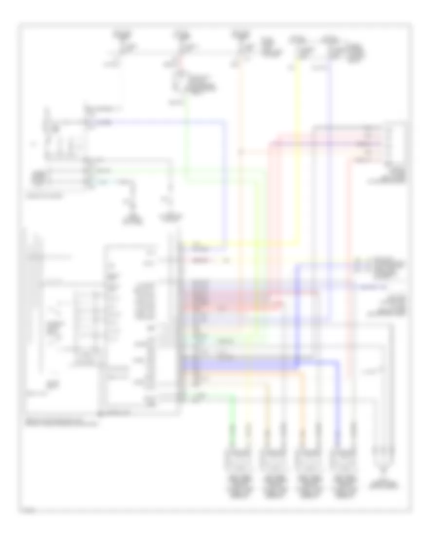
List of elements for Anti-lock Brakes Wiring Diagram for Infiniti QX4 2003:
- 17u
- 39u
- Abs actuator & electric unit (on right side of enigne compartment)
- Abs ind
- Abs st-out
- Actuator
- B55 (at right kick panel)
- Bls
- Combination meter
- Control unit
- Data link connector (dlc) (on lower dash panel, left of steering column)
- Diag-l
- E112 (near cruise control servo)
- Fl in
- Fl out
- Fl ss
- Fl ss gnd
- Fr in
- Fr out
- Fr ss
- Fr ss gnd
- Fuse & fusible link box (in relay box-2)
- Fuse 14 10a
- Fuse 7 7.5a
- Fuse 8 10a
- Fuse block (j/b) (left side of dash)
- Fusible link c 40a
- Fusible link d 40a
- G sen 1 gnd
- G sen 1 sig
- G sen 2 sig
- G sen 2 vcc
- G sensor (w/ 4wd) (below rear of center console)
- Gnd
- Gnd gnd
- Gs1
- Gs2
- Gst
- Hot at all times
- Hot in on or start
- Ign
- Left front wheel speed sensor (on left front wheel hub assembly)
- Left rear wheel speed sensor (on left rear wheel hub assembly)
- M10
- M24
- M25
- M26
- M4 (at left end of dash)
- Meter out
- Motor mon
- Motor relay
- Pnk
- R in
- R out
- Red
- Relay act
- Relay mon
- Relay unit
- Right front wheel speed sensor (on right front wheel hub assembly)
- Right rear wheel speed sensor (on right rear wheel hub assembly)
- Rl ss
- Rl ss gnd
- Rr ss
- Rr ss gnd
- Rxd
- Sila
- Solenoid valve relay
- Stoplight switch (on bracket, above brake pedal)
- Transfer control unit (w/ 4wd) (behind lower center dash panel)
- Txd
- Unified meter control unit
- W/ 4wd
 Čeština
 Dansk
Dansk Deutsch
 Ελληνικά
 English
 English
 Español
 Suomi
Suomi Français
 Français
 עברית
עברית Hrvatski
 Magyar
 Italiano
 日本語
日本語 한국어
한국어 Nederlands
 Português
 Português
 Română
 Русский
 Slovenčina
 Slovenščina
 Svenska
 Türkçe
 中文 (中国)
 Polski