Противоугонная система Сигнализация
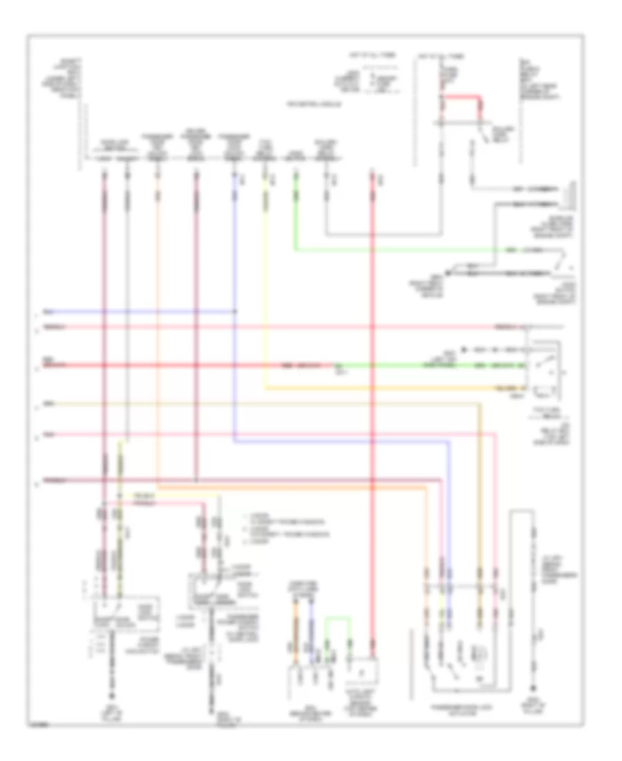
Электросхема открывания авто (1 из 2) для Hyundai Elantra GS 2013
 https://portal-diagnostov.com/license.html
Automotive Electricians Portal FZCO
Automotive Electricians Portal FZCO
https://portal-diagnostov.com/license.html
https://portal-diagnostov.com/license.html
Automotive Electricians Portal FZCO
Automotive Electricians Portal FZCO
Электросхема открывания авто (1 из 2) для Hyundai Elantra GS 2013 - Список элементов:
- 2 door
- 4 door
- B-can
- Burglar alarm relay control
- Computer data lines system
- Door lock relay
- Door lock relay control
- Door unlock relay
- Door unlock relay control
- Dr lk
- Dr lock fuse 20a
- Dr unlk
- Driver door key unlock signal
- Driver door lock actuator
- Driver door lock/ unlock signal
- Fd11
- Fd31
- Fd41
- Gf01 (left "b" pillar)
- Gf03 (left "c" pillar)
- Gf04 (right "c" pillar)
- Gm01 (left top dash panel)
- High
- Hot at all times
- I/p-b
- I/p-c
- I/p-g
- I/p-h
- Ips control module
- Key lk
- Key unlk
- Left rear door lock actuator
- Left rear door lock/ unlock signal
- Low
- Pnk
- Red
- Right rear door lock actuator
- Right rear door lock/ unlock signal
- Smart junction box (under left side of dash, near kick panel)
- Starting/ charging system
- W/ two turn relay
- W/o two turn relay
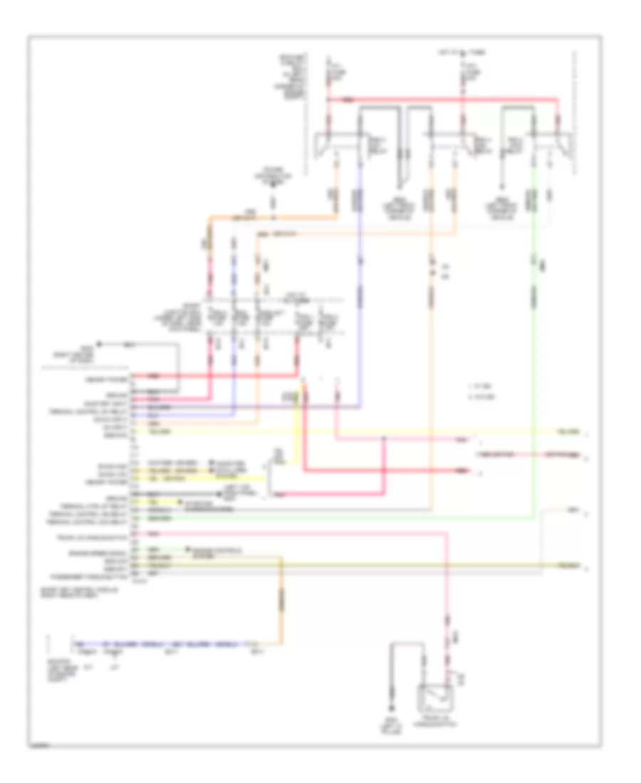
Электросхема открывания авто (2 из 2) для Hyundai Elantra GS 2013
Электросхема открывания авто (2 из 2) для Hyundai Elantra GS 2013 - Список элементов:
- (right front corner of vehicle)
- (top left side of dash)
- 2 door
- 4 door
- Auto light & photo sensor (top center of dash)
- B/alarm horn relay
- B/alarm horn relay control
- Bcm (behind center of dash)
- Burglar alarm horn (right front of engine compt)
- Can h
- Can l
- Computer data lines system
- Door lock
- Door lock switch
- Door unlock
- Dr lk
- Dr unlk
- Driver/ passenger door key lock signal
- E/r fuse & relay box (in left rear corner of engine compt)
- Fd11
- Fd21
- Ge04
- Gf01 (left "b" pillar)
- Gf02 (right "b" pillar)
- Gm01 (left top dash panel)
- Hood switch
- Hood switch (right front of engine compt)
- Horn fuse 15a
- Hot at all times
- I/p-c
- I/p-e
- I/p-g
- I/p-h
- Icm relay box
- Ips control module
- J/c jd01 (sedan: front passenger's door)
- Key lk
- Key unlk
- Leak current auto cut device
- Lock
- M02-b
- M02-c
- M06-a
- Memory fuse 10a
- Mf11
- Nca
- Passenger door key unlock signal
- Passenger door lock actuator
- Passenger door lock/ unlock signal
- Passenger power window switch (w/ central door lock)
- Pnk
- Power window main switch
- Red
- Sec ind
- Smart junction box (under left side of dash, near kick panel)
- Two turn relay
- Two turn relay control
- Unlock
- W/ safety power windows
- W/o safety power windows
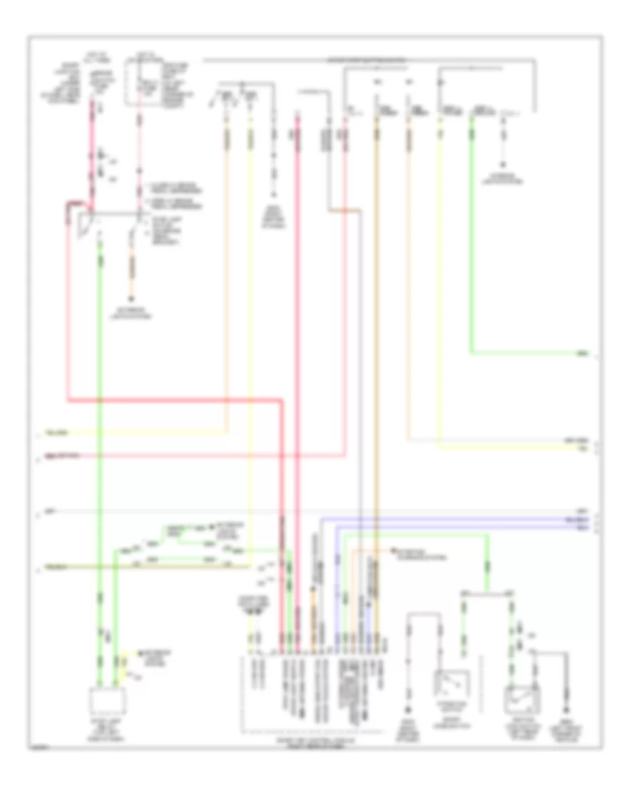
Электросхема иммобилайзера, С Система безключевого доступа (1 из 3) для Hyundai Elantra GS 2013
Электросхема иммобилайзера, С Система безключевого доступа (1 из 3) для Hyundai Elantra GS 2013 - Список элементов:
- (left top dash panel) gm01
- (or pnk)
- A/t
- Acc/in input
- B-can high
- B-can low
- Bcm fuse 7.5a
- Cng-aa
- Cng-mk
- Computer data lines system
- E/r fuse & relay box (in left rear corner of engine compt)
- Ec11
- Ecm/pcm (left rear of engine compt)
- Em11
- Em61
- Ems com
- Engine controls system
- Engine speed signal
- Ge02 (left front corner of vehicle)
- Gf03 (left "c" pillar)
- Gm02 (right center of dash)
- Ground
- Hot at all times
- I/p-f
- I/p-h
- Ig 1 fuse 40a
- Ig 2 fuse 40a
- M/t
- M13-a
- Md ud
- Memory power
- Mf61
- Module 7 fuse 7.5a
- On input
- On/start input
- Passenger toggle button
- Pdm 1 fuse 25a
- Pdm 2 (acc) relay
- Pdm 2 fuse 7.5a
- Pdm 3 (ig1) relay
- Pdm 3 fuse 7.5a
- Pdm 4 (ig2) relay
- Pnk
- Power distribution system
- Red
- Smart junction box (under left side of dash, near kick panel)
- Smart key control module (right rear of dash)
- Ssb sw1
- Ssb sw2
- Starting/ charging system
- Terminal control acc relay
- Terminal control ig1 relay
- Terminal control ig2 relay
- Terminal ctrl st relay
- Trunk lid handle switch
- W/ isg
- W/o isg
Электросхема иммобилайзера, С Система безключевого доступа (2 из 3) для Hyundai Elantra GS 2013
Электросхема иммобилайзера, С Система безключевого доступа (2 из 3) для Hyundai Elantra GS 2013 - Список элементов:
- (ill -)
- (or pnk)
- (or pnk) red
- A/t
- B+ (ill +)
- Brake
- Brake light switch
- C-can high
- C-can low
- Close w/ brake
- Computer data lines system
- Driver toggle button
- E/r fuse & relay box (in left rear corner of engine compt)
- Ecu 3 fuse 10a
- Em11
- Em61
- Exterior lights system
- External buzzer
- Ge02 (left front corner of vehicle)
- Gm02 (right center of dash)
- Hot at all times
- Hot in on or start
- I/p-f
- Ignition lock switch (left rear of dash)
- Immo antenna ground
- Immo antenna power
- Interior lights system
- K-line
- Lines system computer data
- M/t
- M13-b
- Mf61
- Open w/ brake
- P position ignition lock sw
- P position switch
- Pedal depressed
- Pnk
- Red
- Smart junction box (under left side of dash, near kick panel)
- Smart key control module (right rear of dash)
- Sport mode switch
- Ssb amber
- Ssb green
- Ssb ill ground
- Ssb ill power
- Ssb sw 1
- Ssb sw 2
- Start feedback signal (m/t) (a/t)
- Start stop button switch
- Starting/ charging system
- Stop lamp power
- Stop lamp relay (top left side of dash)
- Stop lamp switch (on brake pedal bracket)
- Switch fuse 10a
- System anti-lock brakes
- Wheel sen output (fr)
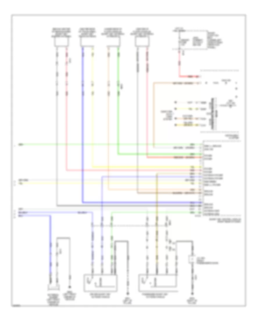
Электросхема иммобилайзера, С Система безключевого доступа (3 из 3) для Hyundai Elantra GS 2013
Электросхема иммобилайзера, С Система безключевого доступа (3 из 3) для Hyundai Elantra GS 2013 - Список элементов:
- (behind center of rear bumper) smart key bumper antenna
- (center of floor console) smart key antenna (interior 1)
- (center rear of trunk area) smart key trunk antenna
- (under rear of floor console) smart key antenna (interior 2)
- Antenna gnd
- Antenna power
- Computer data lines system
- Driver smart key outside handle
- Ee11
- External buzzer (left front corner of vehicle)
- Fd11
- Fd21
- Fr11
- Ge02 (left front corner of vehicle)
- Gf01 (left "b" pillar)
- Gf02 (right "b" pillar)
- Ground
- High
- Hot at all times
- I/p-h
- Immo ind
- Instrument cluster
- J/c jd01 (front passenger's door)
- Key out ind
- Leak current autocut device
- Lock
- Low
- M13-c
- Memory fuse 10a
- Mf61
- Micom
- Nca
- Passenger smart key outside handle
- Power
- Red
- Smart junction box (under left side of dash, near kick panel)
- Smart key control module (right rear of dash)
- Ssb green
- Ssb ill ground
- Ssb ill power
- Transceiver b-can
- Transceiver c-can
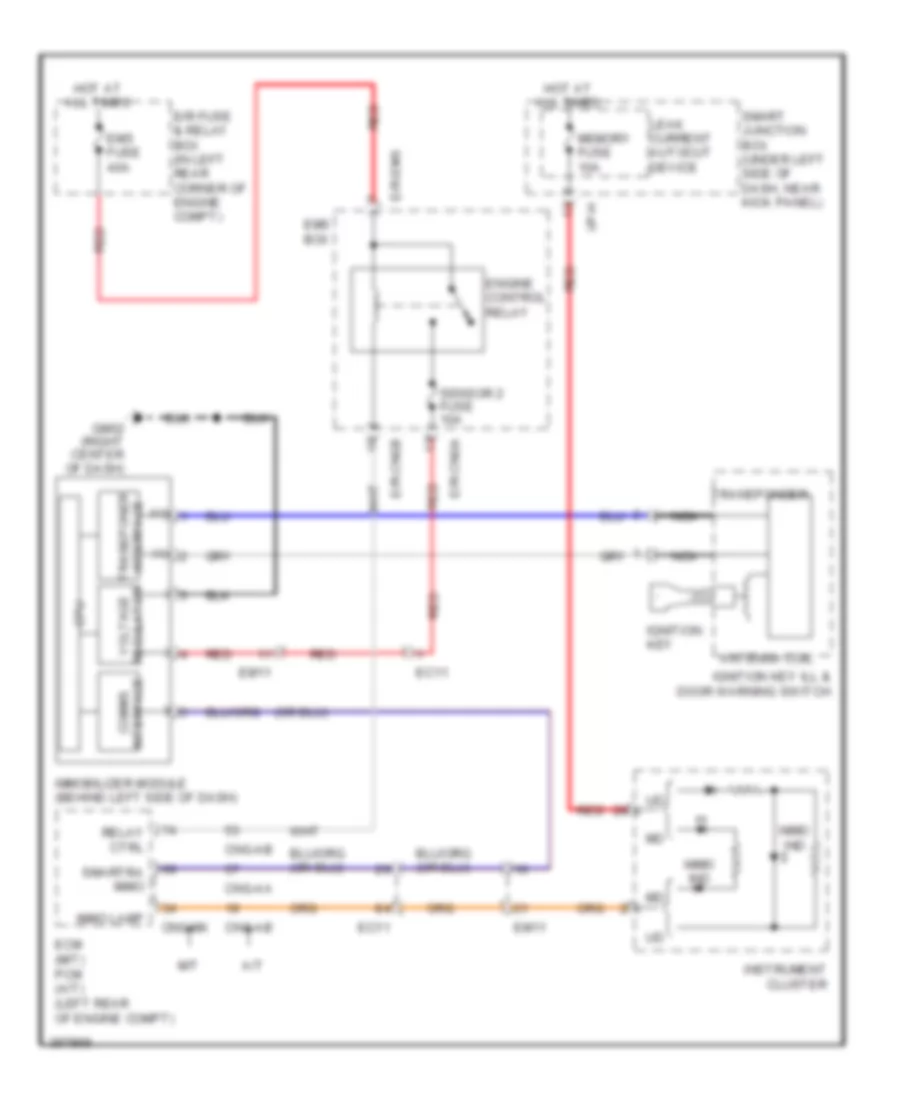
Электросхема иммобилайзера, без системы безключевого доступа Система для Hyundai Elantra GS 2013
Электросхема иммобилайзера, без системы безключевого доступа Система для Hyundai Elantra GS 2013 - Список элементов:
- (+)
- (-)
- A/t
- Antenna coil
- Cng-aa
- Cng-ab
- Cng-mk
- Cpu
- E/r fuse & relay box (in left rear corner of engine compt)
- E/r-cnga
- E/r-cngb
- E/r-ems
- Ec11
- Ecm (m/t) pcm (a/t) (left rear of engine compt)
- Em11
- Ems box
- Ems fuse 40a
- Engine control relay
- Gm02 (right center of dash)
- Hot at all times
- I/p-h
- Ignition key
- Ignition key ill & door warning switch
- Immo ind
- Immo lamp
- Immobilizer module (behind left side of dash)
- Instrument cluster
- Interface comms
- Interface transponer
- Leak current autocut device
- M/t
- Memory fuse 10a
- Nca
- Red
- Regulator voltage
- Relay ctrl
- Sensor 2 fuse 10a
- Smart junction box (under left side of dash, near kick panel)
- Smartra immo
- Transponder

 Čeština
 Dansk
Dansk Deutsch
 Ελληνικά
 English
 English
 Español
 Suomi
Suomi Français
 Français
 עברית
עברית Hrvatski
 Magyar
 Italiano
 日本語
日本語 한국어
한국어 Nederlands
 Português
 Português
 Română
 Русский
 Slovenčina
 Slovenščina
 Svenska
 Türkçe
 中文 (中国)