POWER DISTRIBUTION
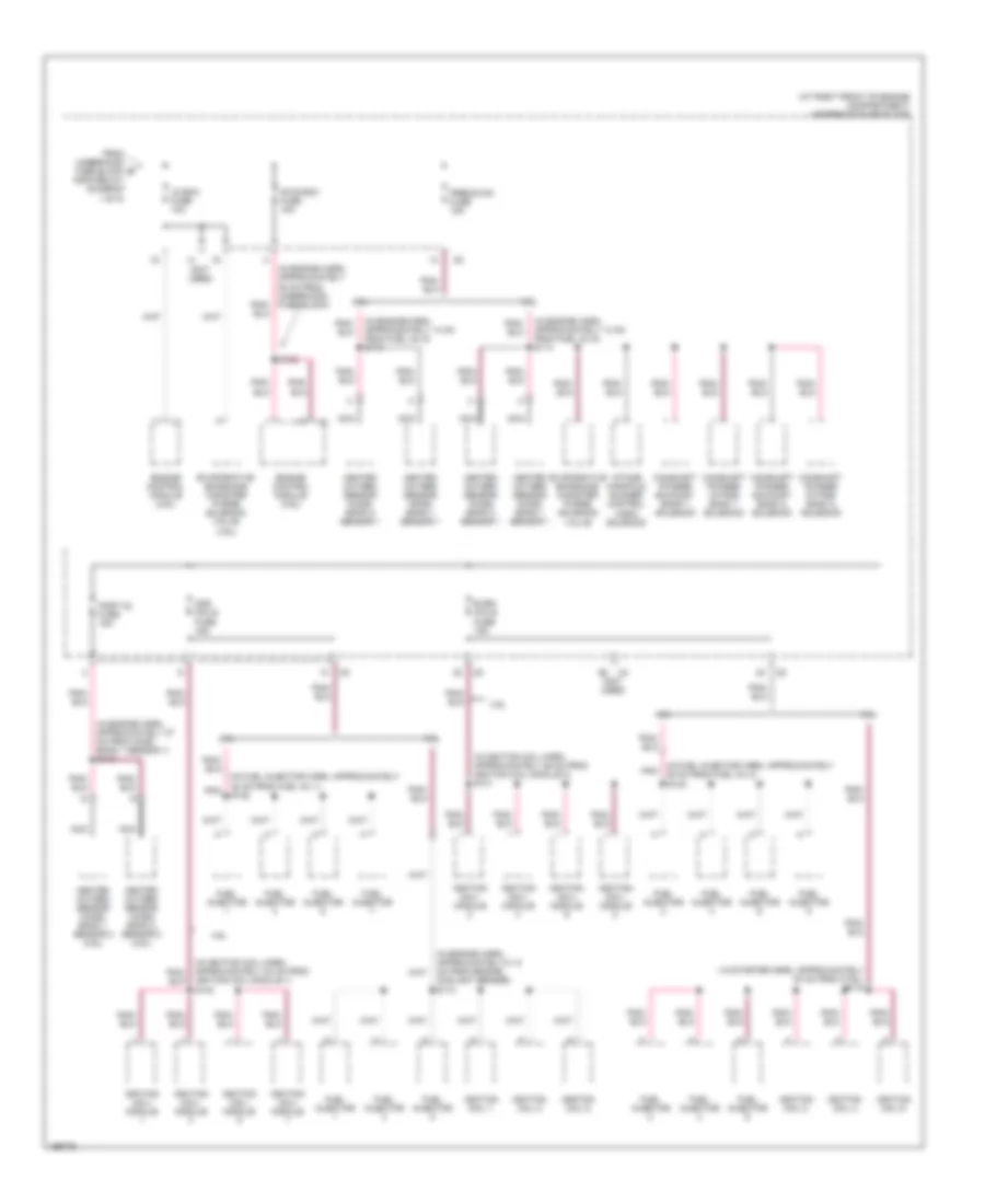
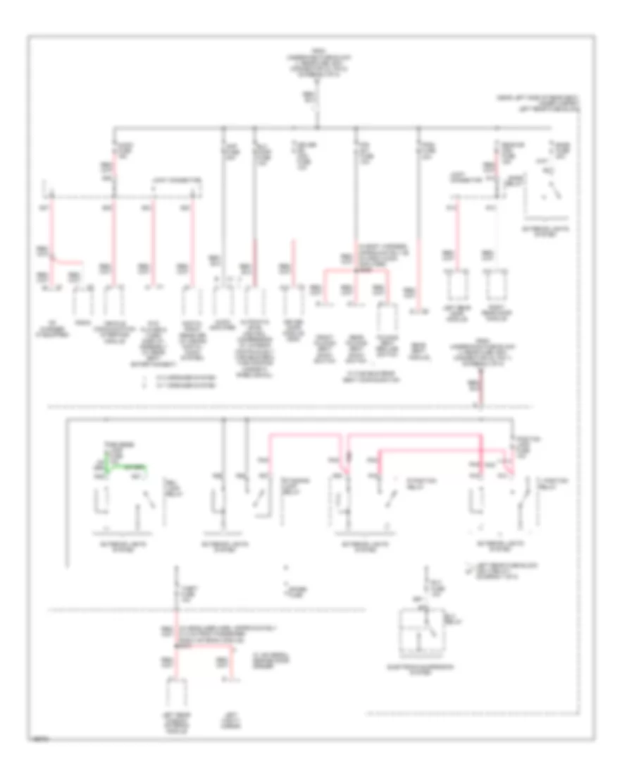
Power Distribution Wiring Diagram (1 of 8) for Cadillac SRX 2005
 https://portal-diagnostov.com/license.html
Automotive Electricians Portal FZCO
Automotive Electricians Portal FZCO
https://portal-diagnostov.com/license.html
https://portal-diagnostov.com/license.html
Automotive Electricians Portal FZCO
Automotive Electricians Portal FZCO
List of elements for Power Distribution Wiring Diagram (1 of 8) for Cadillac SRX 2005:
- (3.6l)
- (4.6l)
- (at right front of engine compartment) underhood fuse block
- (in engine harn, approximately 18.5 cm from fuel inj 1) s118
- 3.6l
- 4.6l
- A12
- Air conditioning & cooling fans systems
- Air conditioning system
- Battery
- Blower fuse 40a
- Blower relay
- Ccp fuse 10a
- Dash integration module
- Data link connector
- Dim/ aldl fuse 10a
- Ebcm fuse 50a
- Ecm/tcm fuse 10a
- Electronic brake control module
- Engine control module
- Engine control module (ecm)
- Flasher fuse 15a
- Generator
- Generator inline fuse 200a
- Hi fan fuse 30a
- Hi speed fan relay
- Hvac control module
- Instrument panel cluster
- Lo speed fan fuse 30a
- Lo speed fan relay
- Main relay
- Main relay control
- R14
- R19
- R20
- R39
- R40
- R47
- R48
- R49
- R50
- R51
- R52
- Red
- S/p fan relay
- Starter
- Theft deterrent module
- To underhood fuse block (horn relay) (diagram 3 of 8)
- To underhood fuse block (v8 ecm fuse, 10a) (diagram 2 of 8)
- Transmission control module
- Turn signal/ hazard flasher module
- Volt check fuse 10a
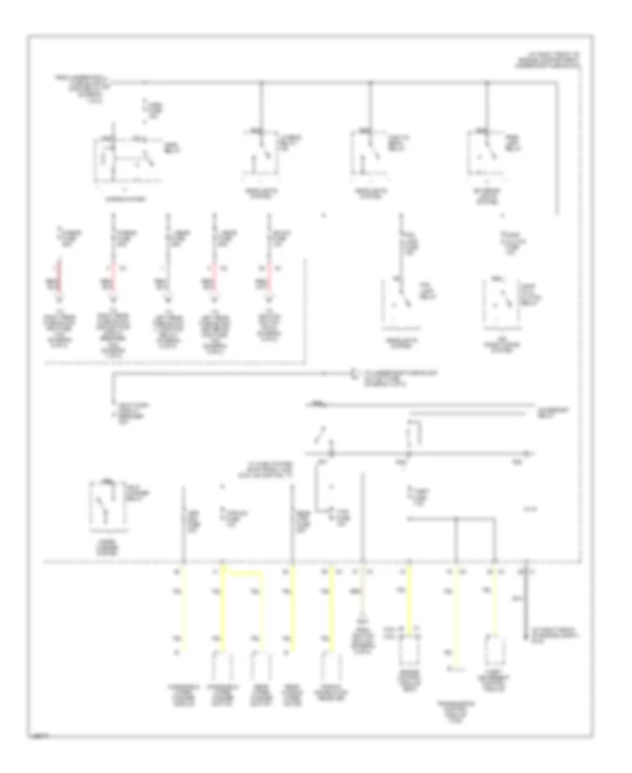
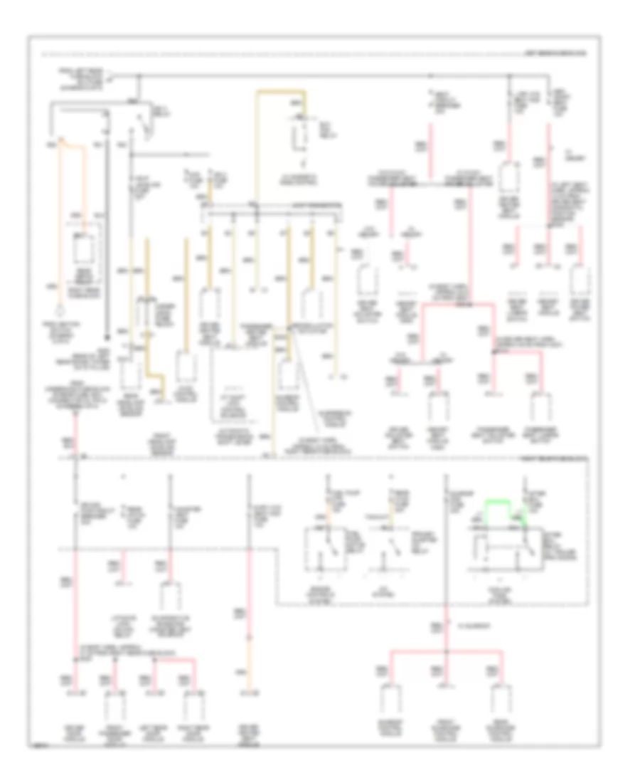
Power Distribution Wiring Diagram (2 of 8) for Cadillac SRX 2005
List of elements for Power Distribution Wiring Diagram (2 of 8) for Cadillac SRX 2005:
- ( in starter harn, approximately 30 cm from c108 ) s119
- (at right front of engine compartment) underhood fuse block
- (in engine harn, approximately 14 cm from fuel inj 5) s114
- (in engine harn, approximately 37 cm from ho2s bank 1 sensor 1) s113
- (in fuel injector harn, approximately 25 cm from fuel inj 2)
- (in fuel injector harn, approximately 30 cm from fuel inj 1) s122
- (in ignition coil harn, approximately 30 cm from ignition coil module 1) s142
- (in ignition coil harn, approximately 36 cm from ignition coil module 2) s131
- (not used)
- 3.6l
- 4.6l
- Camshaft phaser exhaust bank 1 solenoid
- Camshaft phaser exhaust bank 2 solenoid
- Camshaft phaser intake bank 1 solenoid
- Camshaft phaser intake bank 2 solenoid
- Coolant sensor)
- Engine control module (3.6l)
- Engine control module (4.6l)
- Evaporative emissions canister purge solenoid valve
- Evaporative emissions canister purge solenoid valve (4.6l)
- Even coils fuse 15a
- From underhood b fuse block (main relay) (diagram 1 of 8)
- Fuel injector
- Heated oxygen sensor (ho2s) bank 1 sensor 1
- Heated oxygen sensor (ho2s) bank 1 sensor 2 (3.6l)
- Heated oxygen sensor (ho2s) bank 2 sensor 1
- Heated oxygen sensor (ho2s) bank 2 sensor 2 (3.6l)
- Hfv6 ecm fuse 15a
- Ignition coil 1
- Ignition coil 2
- Ignition coil 3
- Ignition coil 4
- Ignition coil 5
- Ignition coil 6
- Ignition coil/ module
- Intake manifold runner control (imrc) solenoid
- Nca
- Odd coils fuse 15a
- Pnk
- Post 02 fuse 15a
- Pre02/cam fuse 15a
- S102
- S112
- S123
- V8 ecm fuse 10a
Power Distribution Wiring Diagram (3 of 8) for Cadillac SRX 2005
List of elements for Power Distribution Wiring Diagram (3 of 8) for Cadillac SRX 2005:
- (3.6l)
- (4.6l)
- (at right front of engine compartment) underhood fuse block
- (at right front of engine compt) g104
- Accessory relay
- Air conditioning system
- Comp (clu) clutch relay
- Comp clutch fuse 10a
- Engine control module (ecm)
- Exterior lights system
- Fog lamp fuse 15a
- Fog lamp relay
- From ignition switch (diagram 5 of 8)
- From underhood fuse block a (main relay) (diagram 1 of 8)
- Hdlp wash circuit breaker 30a
- Hdlp washer relay
- Headlights system
- High (hi) beam relay
- Horn fuse 15a
- Horn relay
- Horns system
- Ign sw fuse 10a
- L rear fuse 60a
- Lo beam relay/ hid
- Park lamp relay
- R rear fuse 60a
- R10
- R11
- R24
- R28
- R32
- R35
- R36
- R37
- R38
- R56
- R68
- Rear window wiper motor
- Rear wiper/ washer switch
- Rear wpr fuse 25a
- Theft deterrent control module
- Theft fuse 7.5a
- To ignition switch (pin 6) (diagram 5 of 8)
- To left rear fuse block (driver dr mod fuse, 10a) (diagram 6 of 8)
- To left rear fuse block (l position relay) (diagram 6 of 8)
- To right rear fuse block (dr mod pwr circuit breaker, 30a) (diagram 7 of 8)
- To right rear fuse block (rim fuse, 10a) (diagram 5 of 8)
- To underhood fuse block outlet fuse (diagram 4 of 8)
- Traffic information receiver
- Transmission control module (tcm)
- Vics fuse 10a
- W/ avec system am/fm radio, mcd, dvd, navigation, tv
- Windshield wiper/ washer module
- Windshield wiper/ washer switch
- Wiper/ washer system
- Wpr mod fuse 30a
- Wpr sw fuse 10a
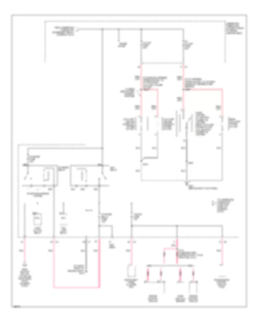
Power Distribution Wiring Diagram (4 of 8) for Cadillac SRX 2005
List of elements for Power Distribution Wiring Diagram (4 of 8) for Cadillac SRX 2005:
- (accessory relay) (diagram 3 of 8)
- (at right front of engine compt) g104
- (in console harness, approximately 20 cm from right auxiliary power outlet)
- (in i/p harness, approximately 37 cm from inside air temperature sensor)
- (not used)
- 3.6l
- 4.6l
- Approximately 16 cm from fuel inj 3)
- Auxiliary center console 1 power outlet
- Auxiliary center console 2 power outlet
- Cigar lighter (w/ ashtray cigarette lighter) front auxiliary power outlet (w/o ashtray cigarette lighter)
- Coil
- Comp clutch relay
- Engine control module
- Fog lamp relay
- From ignition switch (via splice pack sp200 (pin 8) (diagram 5 of 8)
- From underhood fuse block h
- G201 (behind right kick panel)
- I/p outlet fuse 20a
- Ign 1 relay
- Instrument panel cluster (ipc)
- Mass air flow sensor
- Outlet fuse 20a
- Pnk
- R43
- R44
- R45
- R46
- R55
- R63
- R64
- Rear auxiliary power outlet
- S115 (in engine harn, pnk
- S200
- S315
- S316
- S353
- Spare fuse
- Starter fuse 30a
- Starter relay
- Starter relay fuse 10a
- Starting/charging system
- Tcm/ipc fuse 15a
- To underhood fuse block (wash noz fuse 10a, (diagram 5 of 8)
- Transmission control module (tcm)
- Underhood fuse block (at right front of engine compartment)
- W/ rear seat enter- tainment package
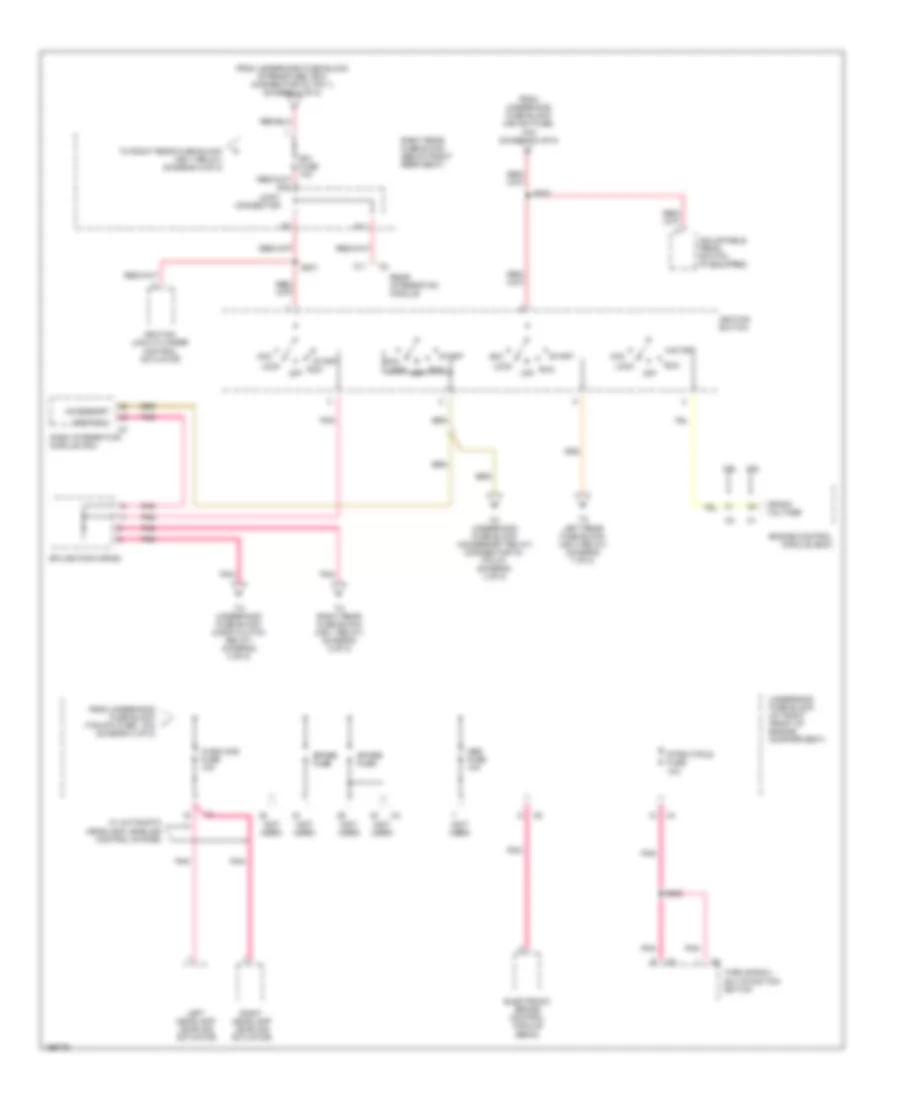
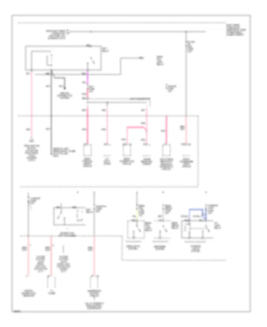
Power Distribution Wiring Diagram (5 of 8) for Cadillac SRX 2005
List of elements for Power Distribution Wiring Diagram (5 of 8) for Cadillac SRX 2005:
- (not used)
- 3.6l
- 4.6l
- A11
- Abs fuse 10a
- Acc
- Accessory
- Adjustable pedal switch (if equipped)
- Crank voltage
- Dash integration module (dim)
- Electronic brake control module (ebcm)
- Engine control module (ecm)
- From underhood fuse block (ign sw fuse, 10a) (diagram 3 of 8)
- From underhood fuse block (r rear fuse, 60a) (connector c3, pin 1) (diagram 3 of 8)
- From underhood fuse block (tcm/ipc fuse, 10a) (diagram 4 of 8)
- Ignition 1
- Ignition lock cylinder control actuator
- Ignition switch
- Joint connector
- Left headlamp leveling actuator
- Lock
- Lock off
- Off
- Pnk
- Rear integration module
- Right headlamp leveling actuator
- Right rear fuse block (below right rear seat)
- Rim fuse 10a
- Run
- S11
- S201
- S202
- S203
- Spare fuse
- Splice pack sp200
- Start
- Strg ctrls fuse 10a
- To left rear fuse block (ign 3 relay) (diagram 7 of 8)
- To right rear fuse block (ign 1 relay) (diagram 8 of 8)
- To underhood fuse block (accessory relay) (connector c4, pin 37) (diagram 3 of 8)
- To underhood fuse block (comp clutch relay) (diagram 4 of 8)
- Turn signal/ multifunction switch
- Underhood fuse block (at right front of engine compartment)
- W/ automatic headlamp leveling control system
- Wash noz fuse 10a
Power Distribution Wiring Diagram (6 of 8) for Cadillac SRX 2005
List of elements for Power Distribution Wiring Diagram (6 of 8) for Cadillac SRX 2005:
- (in body harness, approximately 95 cm from audio amplifier) s306
- (near left side of rear seat, under carpet) left rear fuse block
- 21.5 cm from passenger radio antenna module) s313
- A12
- Amp fuse 30a
- Audio amplifier
- Audio fuse 15a
- Automatic level control compressor (w/ chassis continuously variable real time damping magneto rheological)
- Bass fuse 20a
- Bass relay
- Cd changer (if equipped)
- Digital radio receiver (w/ 5-band digital audio system)
- Driver door module (ddm)
- Driver dr mod fuse 10a
- Dvd player & video display assembly (w/ rear seat entertainment)
- Elc comp fuse 10a
- Elc fuse 10a
- Elc relay
- Electronic suspension system
- Exterior lights system
- Ffs sw fuse 10a
- Ffsm fuse 30a
- Folding seat recline switch
- From underhood fuse block (l rear fuse, 60a) (connector c2, pin 1) (diagram 3 of 8)
- From underhood fuse block (l rear fuse, 60a) (connector c2, pin 2) (diagram 3 of 8)
- Front folding seat show switch
- Joint connector
- L position relay
- Left rear door module
- Left rear fuse block (ign 3 relay) (diagram 7 of 8)
- Left rear window antenna module
- Left vanity mirror
- Pnk
- Position lamp fuse 10a
- R position relay
- R13
- R15
- R18
- R20
- R26
- R27
- R29
- R36
- R37
- Radio
- Rear dr mod fuse 15a
- Rear folding seat show switch
- Rear seat module
- Rev lamp relay
- Right rear door module
- S12
- S13
- S14
- S24
- S25
- S26
- S27
- S28
- Spare fuse
- Standing lamp relay
- Theft fuse 10a
- Vehicle communication interface module
- W/ 7 speaker system
- W/ 8 speaker system
- W/ flexible rear seat configuration
- W/ universal garage door opener
Power Distribution Wiring Diagram (7 of 8) for Cadillac SRX 2005
List of elements for Power Distribution Wiring Diagram (7 of 8) for Cadillac SRX 2005:
- (in body harn, approx 10 cm from right rear fuse block)
- (in body harn, approx 21 cm from right rear fuse block) s303
- (in body harn, approx 54.5 cm from sdm) s304
- (in driver seat harn, approx 45 mm from c307) s318
- (in left seat harn, approx 10 cm from driver seat horizontal position sensor) s348
- A/c system
- A/t shift lock control solenoid
- After boil relay (w/ trailer provisions)
- Automatic transmission shift lever
- B11
- Canister vent fuse 10a
- Ccp fuse 10a
- Cooling fans system
- Dr mod pwr circuit breaker 30a
- Driver adjuster seat switch
- Driver door module
- Driver heated seat module
- Driver power seat switch
- Driver seat adjuster switch
- Driver seat lumbar switch
- Elc fan relay
- Engine controls system
- Evaporative emissions canister vent solenoid
- From ignition switch (diagram 5 of 8)
- From left rear fuse block w elc fuse (diagram 6 of 8)
- From underhood fuse block (r rear fuse, 60a) (connector c3, pin 2) (diagram 3 of 8)
- Front headlamp leveling sensor
- Front passenger door module
- Front sunshade control module
- Fuel pump motor relay
- Fuel pump mtr fuse 15a
- G402 (rear of left rear shock tower on "d" pillar)
- Hdlp leveling fuse 10a
- Hvac control module
- Ign 3 fuse 10a
- Ign 3 relay
- Joint connector
- L frt htd seat mod fuse 10a
- Left rear door module
- Left rear fuse block
- Liftgate lock/ unlock relay
- Mem/ adapt seat fuse 10a
- Memory seat module
- Memory seat module (msm)
- Nca
- Passenger heated seat module
- Passenger seat adjuster switch
- Passenger seat lumbar switch
- Primary quarter a/c relay
- R frt htd seat mod fuse 10a
- R11
- R12
- R21
- R22
- R23
- R25
- R37
- Rear defog relay
- Rear hatch fuse 10a
- Rear headlamp leveling sensor
- Rear hvac fuse 30a
- Rear sunshade control module
- Recirculation actuator
- Right rear door module
- Right rear fuse block
- S302
- Seat circuit breaker 30a
- Sunroof control module
- Sunroof mod fuse 40a
- Suspension control module
- Under- hood fuse block
- W/ 8-way passenger seat power adjuster
- W/ magnetic ride control
- W/ memory
- W/ sunroof
- W/o 8-way passenger seat power adjuster
- W/o memory
Power Distribution Wiring Diagram (8 of 8) for Cadillac SRX 2005
List of elements for Power Distribution Wiring Diagram (8 of 8) for Cadillac SRX 2005:
- (rear of left rear shock tower on "d" pillar) g402
- 4.6l w/ magnetic ride control suspension
- A/t shift lever
- A12
- Air bag fuse 10a
- Defogger system
- From ignition switch (via splice pack sp200, pin 9) (diagram 5 of 8)
- From right rear fuse block (rim fuse, 10a) (diagram 5 of 8)
- Front passenger door module
- Ground distribution system
- Headlights system
- Ign 1 fuse 10a
- Ign 1 relay
- Inflatable restraint sensing & diagnostic module
- Information not available
- Inside rearview mirror
- Int lamp relay
- Interior lamp fuse 10a
- Interior lights system
- Joint connector
- Pnk
- R16
- R17
- R21
- R22
- R23
- R25
- R26
- R27
- R31
- R32
- Rap relay
- Rear defog fuse 40a
- Rear defog relay
- Rear fog lamp fuse 10a
- Rear fog lamp relay
- Rear integration module
- Rear parking assist module
- Right rear fuse block (near right side of rear seat, under carpet)
- Rt frt dr mod fuse 10a
- S25
- S26
- S27
- S28
- Suspension control module
- Suspntn fuse 25a
- Traffic information receiver
- Tv tuner
- Vics/rap fuse 10a
- W/avec system, am/fm radio, icdx navigation, cd-rom & tv
- W/avec system, am/fm radio, mcd, dvd, navigation & tv

 Čeština
 Dansk
Dansk Deutsch
 Ελληνικά
 English
 English
 Español
 Suomi
Suomi Français
 Français
 עברית
עברית Hrvatski
 Magyar
 Italiano
 日本語
日本語 한국어
한국어 Nederlands
 Português
 Português
 Română
 Русский
 Slovenčina
 Slovenščina
 Svenska
 Türkçe
 中文 (中国)