AIR CONDITIONING
Heater Wiring Diagram for Ford Focus ZX3 2004
 https://portal-diagnostov.com/license.html
Automotive Electricians Portal FZCO
Automotive Electricians Portal FZCO
https://portal-diagnostov.com/license.html
https://portal-diagnostov.com/license.html
Automotive Electricians Portal FZCO
Automotive Electricians Portal FZCO
List of elements for Heater Wiring Diagram for Ford Focus ZX3 2004:
- (at left ``a" pillar) g204
- (at right ``a" pillar) g203
- (in main wiring
- (in main wiring harness, near breakout for instrument cluster) s224
- (not used)
- 15-fa13
- 29-fa13
- 29s-le10
- 31s-fa26
- 31s-hb22
- 31s-hb31
- 32-fa76
- 33-fa76
- 91-fa13
- 91s-fa20
- Battery junction box (bjb) (in left rear corner of engine compartment)
- Blower motor resistor (behind center of dash)
- C270a
- C270e
- Central junction box (cjb) (behind left side of dash)
- Defogger system
- Fuse 40a
- Fuse 7.5a
- Harness, near breakout for instrument cluster) s212
- Heater blower motor (behind center of dash)
- Heater blower switch
- Heater control module (behind dash)
- High
- Hot at all times
- Hot in start or run
- Interior lights system
- Low speed
- Medium high
- Medium low
- Off
- Rear window heater on
- Rear window heater switch
- Rear window heater switch illumination
- Recirculation air actuator (behind right side of dash, next to blower motor)
- Recirculation on
- Recirculation switch
- Recirculation switch illumination
- S249 (in main wiring harness, near breakout for c213)
- Solid state
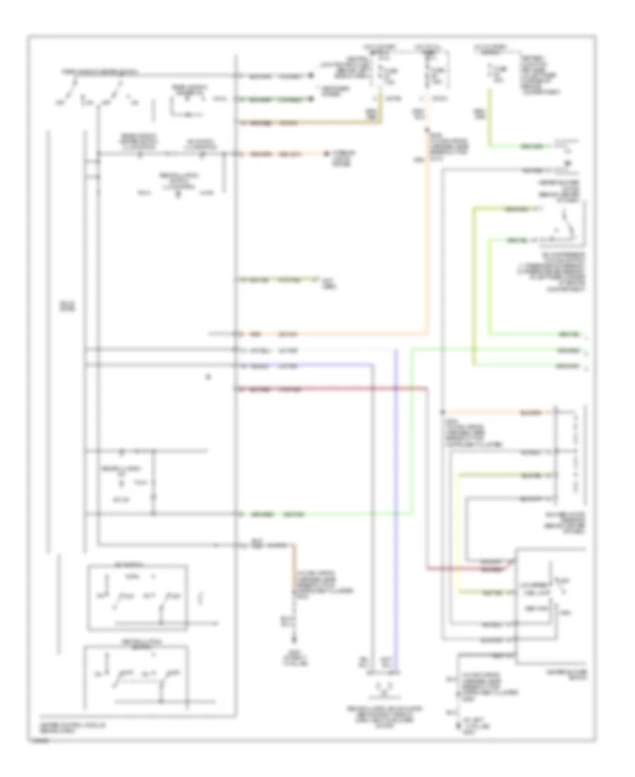
2.0L
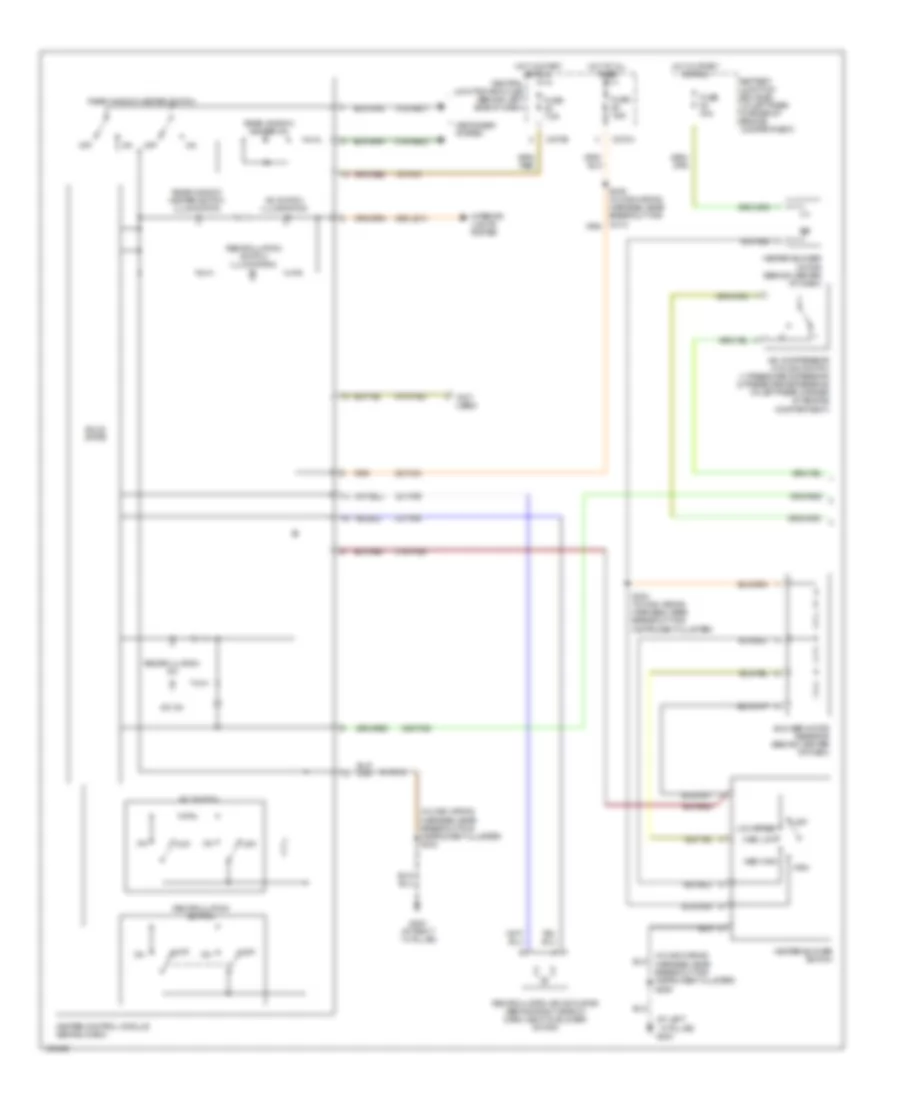
2.0L, Manual A/C Wiring Diagram, Except SVT (1 of 2) for Ford Focus ZX3 2004
List of elements for 2.0L, Manual A/C Wiring Diagram, Except SVT (1 of 2) for Ford Focus ZX3 2004:
- (at left ``a" pillar) g204
- (in main wiring
- (in main wiring harness, near breakout for instrument cluster) s212
- (not used)
- 15-fa13
- 15s-fa38
- 29-fa13
- 29s-le10
- 31s-fa26
- 31s-hb22
- 31s-hb31
- 32-fa76
- 33-fa76
- 91-fa13
- 91s-fa20
- A/c compressor cycling switch (1: pressure increasing) (2: pressure decreasing) (in left rear corner of engine compartment)
- A/c on
- A/c switch
- A/c switch illumination
- Battery junction box (bjb) (in left rear corner of engine compartment)
- Blower motor resistor (behind center of dash)
- C270a
- C270e
- Central junction box (cjb) (behind left side of dash)
- Defogger system
- Fuse 40a
- Fuse 7.5a
- G203 (at right ``a" pillar)
- Harness, near breakout for instrument cluster) s206
- Heater blower motor (behind center of dash)
- Heater blower switch
- Heater control module (behind dash)
- High
- Hot at all times
- Hot in start or run
- Interior lights system
- Low speed
- Med high
- Med low
- Off
- Rear window heater on
- Rear window heater switch
- Rear window heater switch illumination
- Recirculation air actuator (behind right side of dash, next to blower motor)
- Recirculation on
- Recirculation switch
- Recirculation switch illumination
- S224 (in main wiring harness, near breakout for instrument cluster)
- Solid state
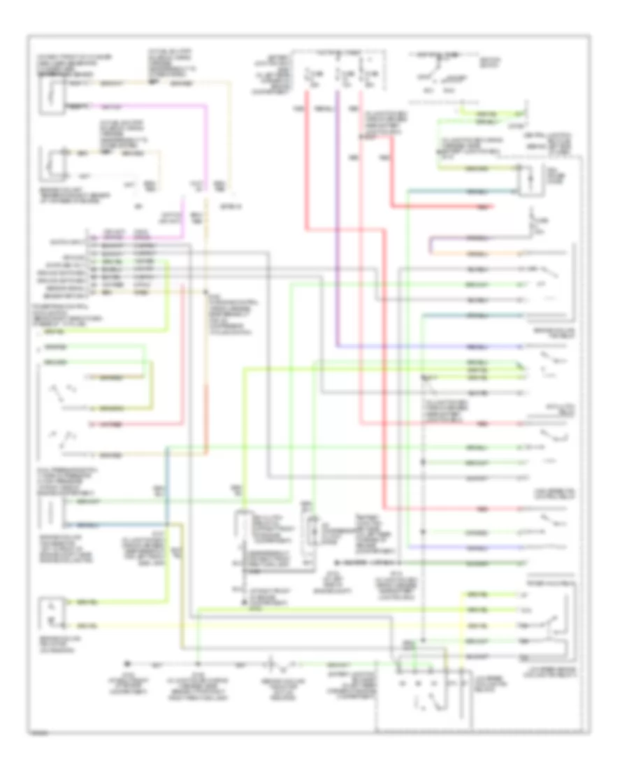
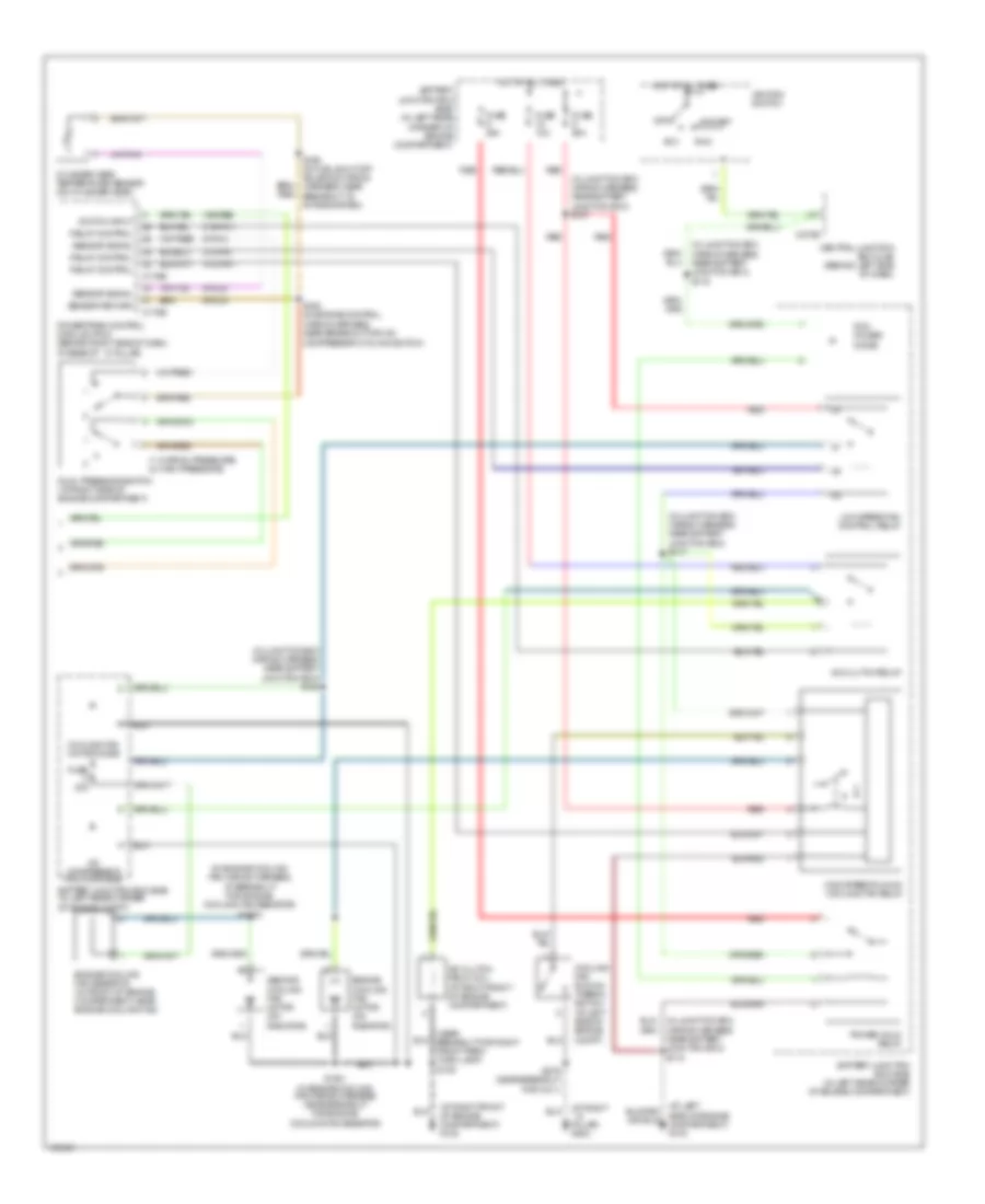
2.0L, Manual A/C Wiring Diagram, Except SVT (2 of 2) for Ford Focus ZX3 2004
List of elements for 2.0L, Manual A/C Wiring Diagram, Except SVT (2 of 2) for Ford Focus ZX3 2004:
- (at right front of engine compartment) g102
- (in fuel shutoff solenoid wiring harness, near breakout to intake system) s198
- (in junction box wiring harness,
- (in junction box wiring harness, near battery junction box) s119
- (in junction box wiring harness, near battery junction box)
- (near breakout for right front park/turn lamp)
- (on right front of cylinder head, near generator) cylinder head temperature sensor
- 15s-re8
- 31s-fa11
- 31s-pa17
- 31s-pa21
- 31s-pa7
- 8-pa13
- 8-rj5 8-rj33
- 87a
- 9-re8
- A/c clutch field coil (at right front of engine compartment)
- A/c clutch relay
- A/c compressor clutch diode
- Acc
- Battery junction box (bjb) (in left rear corner of engine compartment)
- C270e
- Central junction box (cjb) (behind left side of dash)
- Cycling switch)
- Dual pressure switch 1) normal pressure 2) high pressure (at right side of engine compartment)
- Engine coolant temperature (ect) sensor (at top rear of engine)
- Engine cooling fan motor (on radiator)
- Engine cooling fan relay
- Engine cooling fan resistor (svt: in front of engine compt, near engine cooling fan)
- Fuse 10a
- Fuse 20a
- Fuse 30a
- Fuse 50a
- G102 (at right front of engine compartment)
- G103 (at left side of engine compt)
- Ground
- Ground switched
- High speed fan control relay
- Hot at all times
- Ignition switch
- Low speed cooling fan relay b
- Low speed engine cooling fan relay a
- Nca
- Near battery junction box) s107
- Off
- Pcm power diode
- Power hold relay
- Powertrain control module (pcm) (behind right side of dash, at base of ``a" pillar)
- Red
- Run
- S109
- S109 (in junction box wiring harness, near breakout for right front park/turn lamp)
- S117
- S118 (in junction box wiring harness, near battery junction box)
- S137 (in junction box wiring harness, near breakout for left front side lamp)
- S163 (in engine control wiring harness, near breakout for a/c compressor
- Second cooling fan motor (svt: on radiator)
- Sensor return
- Sensor signal
- Spi
- Start
- Switch input
- Switched volt
- Zetec-e
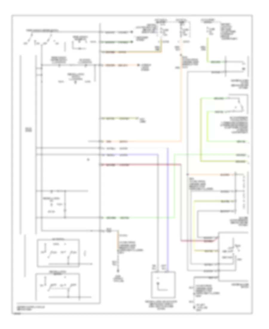
2.0L, Manual A/C Wiring Diagram, SVT (1 of 2) for Ford Focus ZX3 2004
List of elements for 2.0L, Manual A/C Wiring Diagram, SVT (1 of 2) for Ford Focus ZX3 2004:
- (at left ``a" pillar) g204
- (in main wiring
- (not used)
- 15-fa13
- 15s-fa38
- 29-fa13
- 29s-le10
- 31s-fa26
- 31s-hb22
- 31s-hb31
- 32-fa76
- 33-fa76
- 91-fa13
- 91s-fa20
- A/c compressor cycling switch 1) pressure increasing 2) pressure decreasing (in left rear corner of engine compartment)
- A/c on
- A/c switch
- A/c switch illumination
- Battery junction box (bjb) (in left rear corner of engine compartment)
- Blower motor resistor (behind center of dash)
- C270a
- C270e
- Central junction box (cjb) (behind left side of dash)
- Defogger system
- Fuse 40a
- Fuse 7.5a
- G203 (at right ``a" pillar)
- Harness, near breakout for instrument cluster) s206
- Harness, near breakout for instrument cluster) s212
- Harness, near breakout for instrument cluster)
- Heater blower motor (behind center of dash)
- Heater blower switch
- Heater control module (behind dash)
- High
- Hot at all times
- Hot in run or start
- Hot in start or run
- Interior lights system
- Low
- Med high
- Med low
- Off
- Rear window heater on
- Rear window heater switch
- Rear window heater switch illumination
- Recirculation air actuator (behind right side of dash, next to blower motor)
- Recirculation on
- Recirculation switch
- Recirculation switch illumination
- S224 (in main wiring
- Solid state
2.0L, Manual A/C Wiring Diagram, SVT (2 of 2) for Ford Focus ZX3 2004
List of elements for 2.0L, Manual A/C Wiring Diagram, SVT (2 of 2) for Ford Focus ZX3 2004:
- (in fuel shutoff solenoid wiring harness, near breakout to intake system) s198
- (in junction box wiring harness near battery junction box) s102
- (in junction box wiring harness near battery junction box) s117
- (in junction box wiring harness near battery junction box) s119
- (in junction box wiring harness, near battery junction box) s118
- (in junction box wiring
- (in left rear corner of engine compartment) battery junction box (bjb)
- 15s-re8
- 31s-fa11
- 31s-pa7
- 8-pa13
- 8-rj5
- 9-re8
- A/c clutch field coil (at right front of engine compartment)
- A/c clutch relay
- A/c compressor clutch diode
- Acc
- Battery (in left side of engine compt)
- Battery junction box (bjb) (in left rear corner of engine compartment)
- Breakout for right
- C270e
- Central junction box (cjb) (behind left side of dash)
- Dual pressure switch 1) normal pressure 2) high pressure (at right side of engine compartment)
- Engine coolant temperature (ect) sensor (at top rear of engine)
- Engine cooling fan resistor)
- Engine cooling fan motor (on radiator)
- Engine cooling fan relay
- Front park/turn lamp)
- Fuse 10a
- Fuse 20a
- Fuse 30a
- G102 (at right front of engine compartment)
- G103 (at left side of engine compartment)
- Ground switched
- Hot at all times
- Ignition switch
- Lock
- Pcm power diode
- Power hold relay
- Powertrain control module (pcm) (behind right side of dash, at base of "a" pillar)
- Red
- Run off
- S1001 (in engine cooling fan
- S109
- S163 (in engine control wiring harness, near breakout for a/c compressor cycling switch)
- Sensor return
- Sensor signal
- Start
- Switched volt
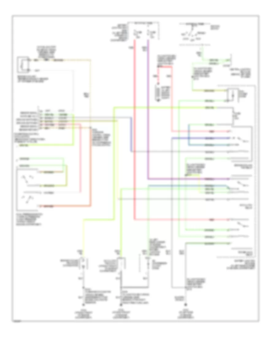
2.3L
2.3L, Manual A/C Wiring Diagram (1 of 2) for Ford Focus ZX3 2004
List of elements for 2.3L, Manual A/C Wiring Diagram (1 of 2) for Ford Focus ZX3 2004:
- (at left ``a" pillar) g204
- (in main wiring
- (in main wiring harness, near breakout for instrument cluster) s212
- (not used)
- 15-fa13
- 15s-fa38
- 29-fa13
- 29s-le10
- 31s-fa26
- 31s-hb22
- 31s-hb31
- 32-fa76
- 33-fa76
- 91-fa13
- 91s-fa20
- A/c compressor cycling switch 1) pressure increasing 2) pressure decreasing (in left rear corner of engine compartment)
- A/c on
- A/c switch
- A/c switch illumination
- Battery junction box (bjb) (in left rear corner of engine compartment)
- Blower motor resistor (behind center of dash)
- C270a
- C270e
- Central junction box (cjb) (behind left side of dash)
- Defogger system
- Fuse 40a
- Fuse 7.5a
- G203 (at right ``a" pillar)
- Harness, near breakout for instrument cluster) s206
- Heater blower motor (behind center of dash)
- Heater blower switch
- Heater control module (behind dash)
- High
- Hot at all times
- Hot in start or run
- Interior lights system
- Low speed
- Med high
- Med low
- Off
- Rear window heater on
- Rear window heater switch
- Rear window heater switch illumination
- Recirculation air actuator (behind right side of dash, next to blower motor)
- Recirculation on
- Recirculation switch
- Recirculation switch illumination
- S224 (in main wiring harness, near breakout for instrument cluster)
- Solid state
2.3L, Manual A/C Wiring Diagram (2 of 2) for Ford Focus ZX3 2004
List of elements for 2.3L, Manual A/C Wiring Diagram (2 of 2) for Ford Focus ZX3 2004:
- (1: normal pressure) (2: high pressure)
- (at left
- (at right front of engine compartment) g102
- (at right ``a" pillar) g202
- (in engine cooling fan wiring harness, at breakout for engine cooling fan resistor) s1002
- (in junction box wiring harness, near battery junction box) s107
- (in junction box wiring harness, near battery junction box) s108
- (in junction box wiring harness, near battery junction box) s117
- (in junction box wiring harness, near battery junction box) s118
- (in junction box wiring harness, near battery junction box) s119
- (near breakout for right front park/ turn lamp) s109
- 15s-re8
- 31s-fa11
- 31s-pa17
- 31s-pa7
- 8-pa13
- 8-rj33
- 9-rj33
- A/c clutch field coil (at right front of engine compartment)
- A/c clutch relay
- A/c compressor clutch diode
- Acc
- Battery junction box (bjb) (in left rear corner of engine compartment)
- Battery junction box (bjb) (in left rear corner of engine compt)
- C175b
- C175e
- C270e
- Central junction box (cjb) (behind left side of dash)
- Compressor cycling switch)
- Cooling fan motor diode
- Cooling fan run-on thermo switch (at left side of engine compt)
- Cylinder head temperature sensor (on cylinder head)
- Dual pressure switch (at right side of engine compartment)
- Engine cooling fan motor (on radiator)
- Engine cooling fan resistor (in front of engine compartment, near engine cooling fan)
- Fuse 10a
- Fuse 20a
- Fuse 30a
- Fuse 50a
- High speed run-on cooling fan relay
- Hot at all times
- Ignition switch
- Low speed fan control relay
- Off
- Pcm power diode
- Power hold relay
- Powertrain control module (pcm) (behind right side of dash, at base of ``a" pillar)
- Red
- Relay control
- Run
- S1001 (in engine cooling fan wiring harness near breakout for engine cooling fan resistor)
- S162 (in engine control wiring harness, near breakout for a/c
- S198 (in fuel shut-off solenoid wiring harness, near breakout to intake system)
- S279 (near breakout for c211)
- Second cooling fan motor (on radiator)
- Sensor return
- Sensor signal
- Side of engine compartment) g103
- Start
- Switch input

 Čeština
 Dansk
Dansk Deutsch
 Ελληνικά
 English
 English
 Español
 Suomi
Suomi Français
 Français
 עברית
עברית Hrvatski
 Magyar
 Italiano
 日本語
日本語 한국어
한국어 Nederlands
 Português
 Português
 Română
 Русский
 Slovenčina
 Slovenščina
 Svenska
 Türkçe
 中文 (中国)