AIR CONDITIONING
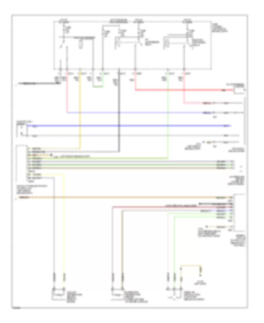
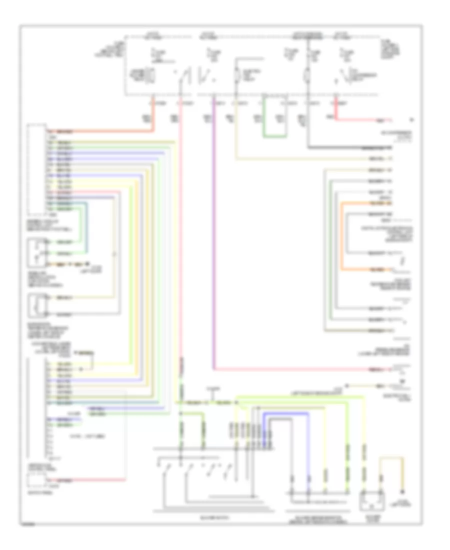
Automatic A/C Wiring Diagram, with Dual Stage Cooling Fans (1 of 2) for MINI Cooper 2007
 https://portal-diagnostov.com/license.html
Automotive Electricians Portal FZCO
Automotive Electricians Portal FZCO
https://portal-diagnostov.com/license.html
https://portal-diagnostov.com/license.html
Automotive Electricians Portal FZCO
Automotive Electricians Portal FZCO
List of elements for Automatic A/C Wiring Diagram, with Dual Stage Cooling Fans (1 of 2) for MINI Cooper 2007:
- (left door)
- Air distribution motor (center console)
- Air stratification flap motor (under right side of dash center console)
- Blower motor
- Blower output stage (center of dash)
- Computer data lines system
- Fuse f30 5a
- Fuse f31 30a
- Fuse f41 5a
- Fuse holder 2 (behind left footwell trim)
- Heat exchanger sensor (behind center of dash)
- Heater blower relay
- Heating & a/c control module
- Hot at all times
- Hot in accy, run and start
- Hot in on or start
- Interior temperature sensor
- Nca
- Power steering control module fan
- Red
- Solar sensor (top of dash)
- Steering control module fan relay (left side of left footwell)
- Switch panel
- X10201
- X10205
- X10207
- X1108
- X1108 (left door)
- X13230 (under left rear seat) (convertible) (left door) (coupe)
- X1879
- X610
- X6454
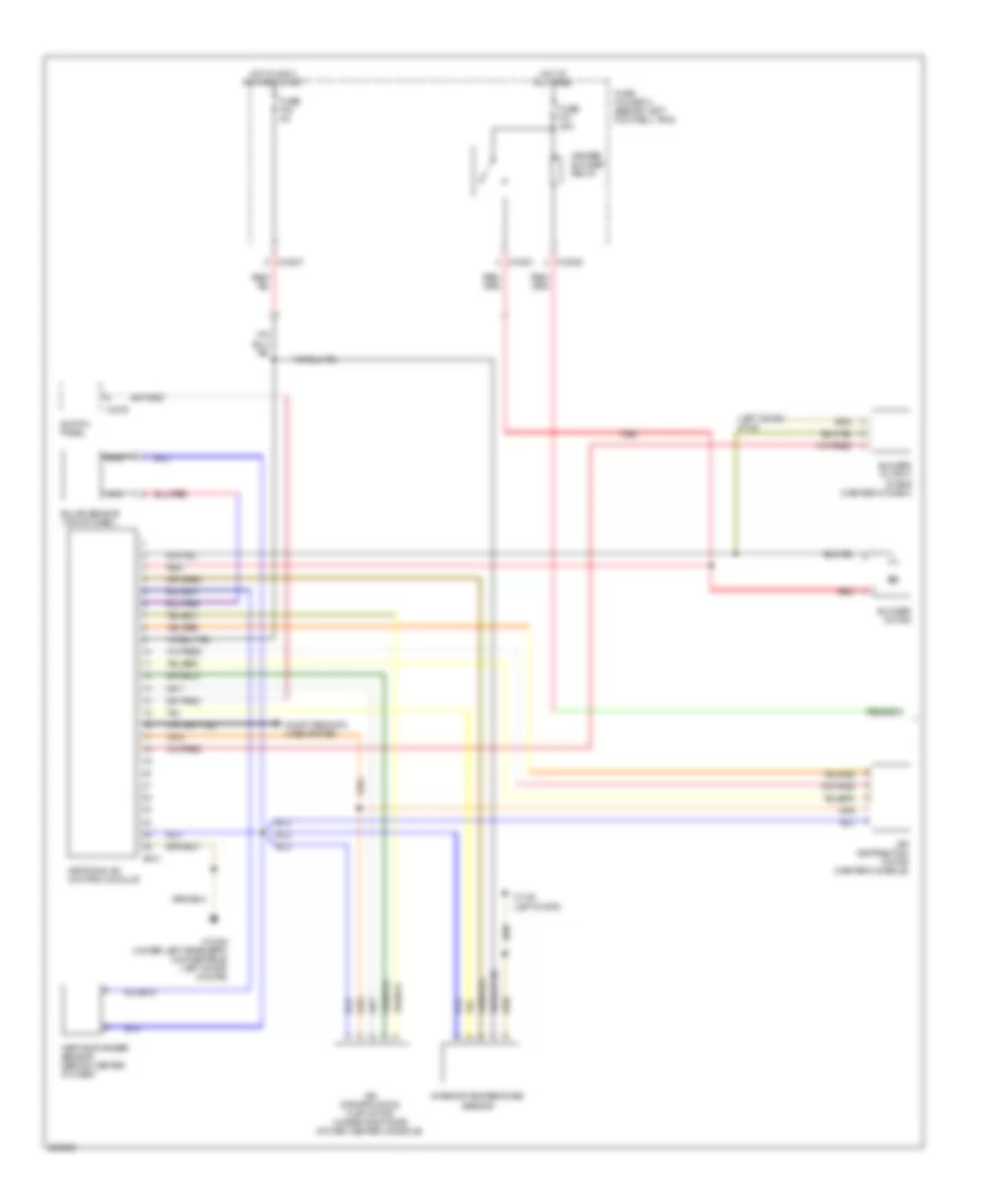
Automatic A/C Wiring Diagram, with Dual Stage Cooling Fans (2 of 2) for MINI Cooper 2007
List of elements for Automatic A/C Wiring Diagram, with Dual Stage Cooling Fans (2 of 2) for MINI Cooper 2007:
- (left side of engine compt)
- A/c compressor clutch
- A/c compressor relay
- A/c pressure sensor (lower left side of engine)
- Computer data lines system
- Coolant temperature sensor (rear of engine)
- Digital motor electronics control unit (left side of engine compt)
- Electric fan 1 motor
- Electric fan relay
- Electric fan stage 2 relay
- Evaporator temperature sensor (under left side of center console)
- Fan switch second stage
- Fresh air/ recirculation flap motor (behind glove box)
- Fuse f03 15a
- Fuse f05 5a
- Fuse f07 30a
- Fuse f08 30a
- Fuse fl9 50a
- Fuse holder 3 (left side of engine compt)
- General module control unit (behind right footwell)
- Hot at all times
- Hot w/ dme main relay energized
- Nca
- Red
- X1108 (left door)
- X167
- X175 (left side of engine compt)
- X179 (convertible: below right rear seat) (coupe: right door)
- X253
- X254
- X255
- X4007
- X4010
- X4013
- X4014
- X53
- X6000
- X60004
- X8687
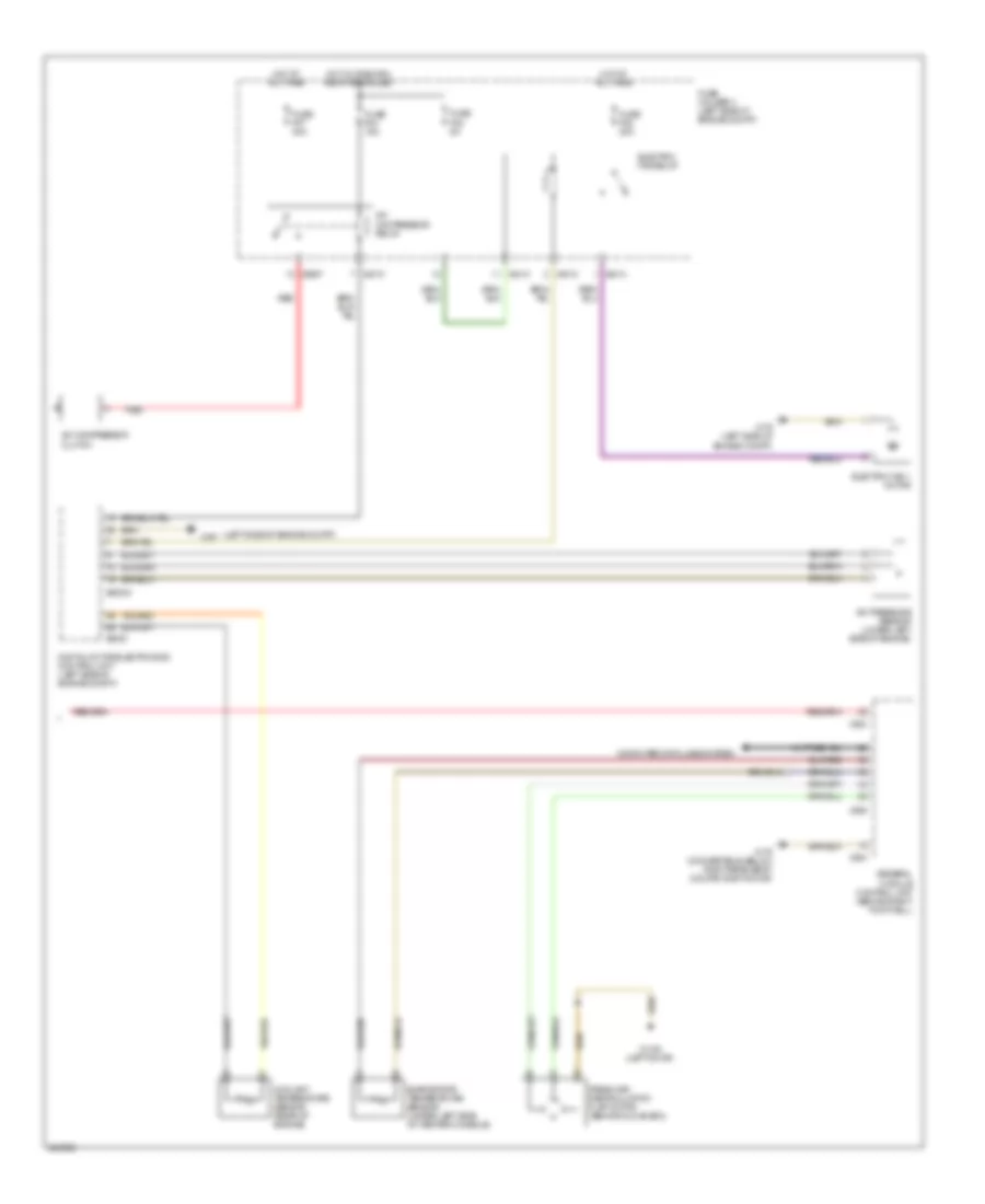
Automatic A/C Wiring Diagram, with Single Stage Cooling Fans (1 of 2) for MINI Cooper 2007
List of elements for Automatic A/C Wiring Diagram, with Single Stage Cooling Fans (1 of 2) for MINI Cooper 2007:
- (left door) x1108
- Air distribution motor (center console)
- Air stratification flap motor (under right side of dash center console)
- Blower motor
- Blower output stage (center of dash)
- Computer data lines system
- Fuse f30 5a
- Fuse f31 30a
- Fuse holder 2 (behind left footwell trim)
- Heat exchanger sensor (behind center of dash)
- Heater blower relay
- Heating & a/c control module
- Hot at all times
- Hot in accy, run and start
- Interior temperature sensor
- Nca
- Red
- Solar sensor (top of dash)
- Switch panel
- X10201
- X10205
- X10207
- X1108 (left door)
- X13230 (under left rear seat) (convertible) (left door) (coupe)
- X1879
- X610
Automatic A/C Wiring Diagram, with Single Stage Cooling Fans (2 of 2) for MINI Cooper 2007
List of elements for Automatic A/C Wiring Diagram, with Single Stage Cooling Fans (2 of 2) for MINI Cooper 2007:
- (left side of engine compt)
- A/c compressor clutch
- A/c compressor relay
- A/c pressure sensor (lower left side of engine)
- Computer data lines system
- Coolant temperature sensor (rear of engine)
- Digital motor electronics control unit (left side of engine compt)
- Electric fan 1 motor
- Electric fan relay
- Evaporator temperature sensor (under left side of center console)
- Fresh air/ recirculation flap motor (behind glove box)
- Fuse f03 15a
- Fuse f05 5a
- Fuse f07 30a
- Fuse f08 20a
- Fuse holder 3 (left side of engine compt)
- General module control unit (behind right footwell)
- Hot at all times
- Hot w/ dme main relay energized
- Red
- X1108 (left door)
- X167
- X175 (left side of engine compt)
- X179 (convertible: below right rear seat) (coupe: right door)
- X253
- X254
- X255
- X4010
- X4013
- X4014
- X6000
- X60004
- X8687
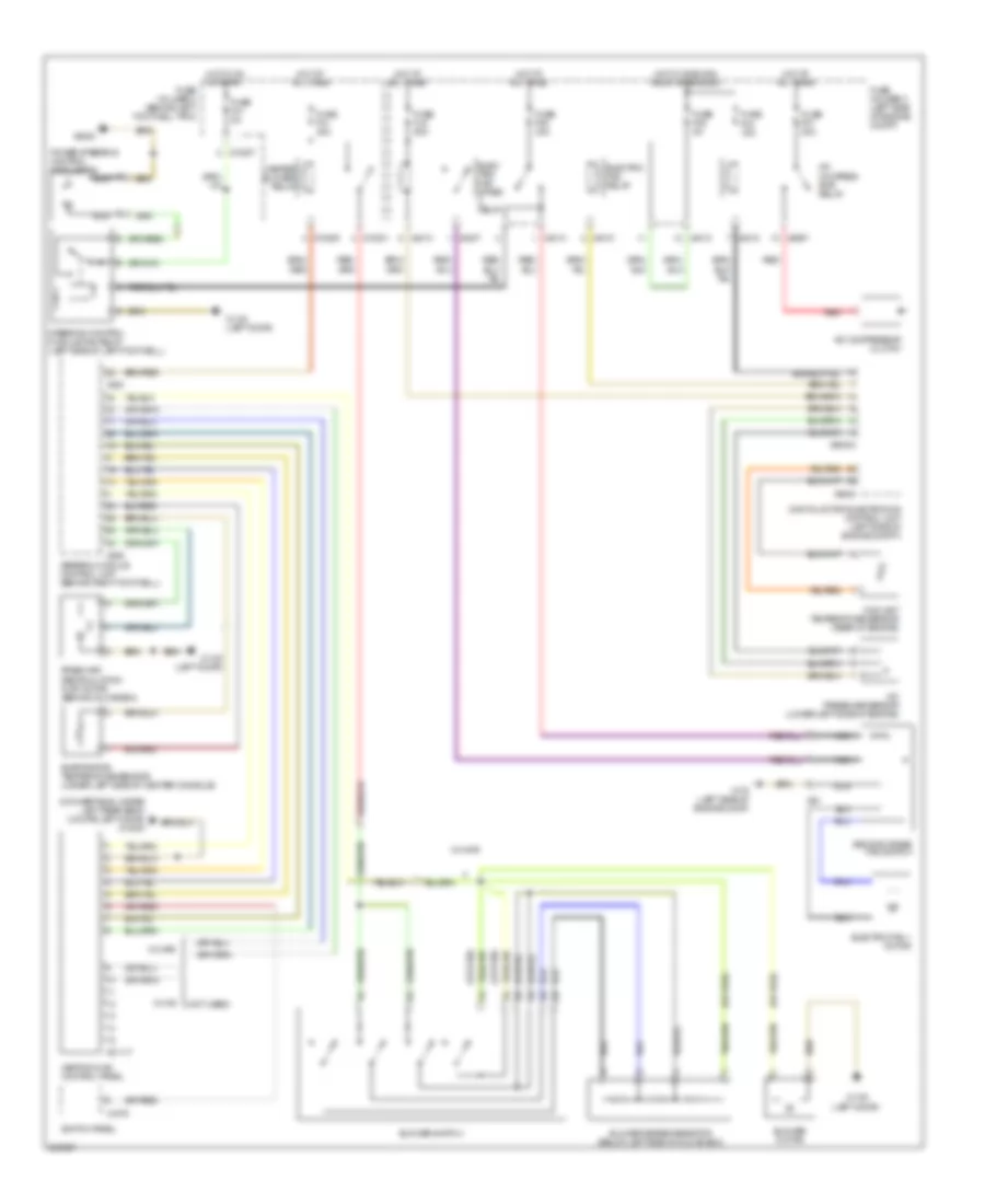
Manual A/C Wiring Diagram, with Dual Stage Cooling Fans for MINI Cooper 2007
List of elements for Manual A/C Wiring Diagram, with Dual Stage Cooling Fans for MINI Cooper 2007:
- (convertible: under left rear seat) (coupe: left door) x13230
- (left door)
- (not used)
- (or red)
- A/c compres- sor relay
- A/c compressor clutch
- A/c pressure sensor (lower left side of engine)
- Blower motor
- Blower series resistor (below left side of glove box)
- Blower switch
- Coolant temperature sensor (rear of engine)
- Digital motor electronics control unit (left side of engine compt)
- Elec- tric fan stage relay
- Electric fan 1 motor
- Electric fan relay
- Evaporator temperature sensor (under left side of center console)
- Fresh air/ recirculation flap motor (behind glove box)
- Fuse f03 15a
- Fuse f05 5a
- Fuse f07 30a
- Fuse f08 30a
- Fuse f31 30a
- Fuse f41 5a
- Fuse fl9 50a
- Fuse holder 2 (behind left footwell trim)
- Fuse holder 3 (left side of engine compt)
- General module control unit (behind right footwell)
- Heater blower relay
- Heating & a/c control panel
- Hot at all times
- Hot in on or start
- Hot w/ dme main relay energized
- Nca
- Power steering control module fan
- Red
- Second stage fan switch
- Steering control module fan relay (left side of left footwell)
- Switch panel
- W/ ihkr
- W/ ihs
- X01117
- X10201
- X10205
- X10207
- X1108
- X1108 (left door)
- X175 (left side of engine comp)
- X1879
- X253
- X255
- X4007
- X4010
- X4013
- X4014
- X53
- X6000
- X60004
- X6454
- X8687
Manual A/C Wiring Diagram, with Single Stage Cooling Fans for MINI Cooper 2007
List of elements for Manual A/C Wiring Diagram, with Single Stage Cooling Fans for MINI Cooper 2007:
- (convertible: under left rear seat) (coupe: left door) x13230
- (left door)
- (not used)
- (or red)
- A/c compressor clutch
- A/c compressor relay
- A/c pressure sensor (lower left side of engine)
- Blower motor
- Blower series resistor (behind left side of glove box)
- Blower switch
- Coolant temperature sensor (rear of engine)
- Digital motor electronics control unit (left side of engine compt)
- Electric fan 1 motor
- Electric fan relay
- Evaporator temperature sensor (under left side of center console)
- Fresh air/ recirculation flap motor (behind glove box)
- Fuse f03 15a
- Fuse f05 5a
- Fuse f07 30a
- Fuse f08 20a
- Fuse f31 30a
- Fuse holder 2 (behind left footwell trim)
- Fuse holder 3 (left side of engine compt)
- General module control unit (behind right footwell)
- Heater blower relay
- Heating & a/c control panel
- Hot at all times
- Hot w/ dme main relay energized
- Red
- Switch panel
- W/ ihkr
- W/ ihs
- X01117
- X10201
- X10205
- X1108
- X1108 (left door)
- X175 (left side of engine compt)
- X1879
- X253
- X255
- X4010
- X4013
- X4014
- X6000
- X60004
- X8687

 Čeština
 Dansk
Dansk Deutsch
 Ελληνικά
 English
 English
 Español
 Suomi
Suomi Français
 Français
 עברית
עברית Hrvatski
 Magyar
 Italiano
 日本語
日本語 한국어
한국어 Nederlands
 Português
 Português
 Română
 Русский
 Slovenčina
 Slovenščina
 Svenska
 Türkçe
 中文 (中国)