SUPPLEMENTAL RESTRAINTS
Supplemental Restraint Wiring Diagram for Oldsmobile Cutlass 1997
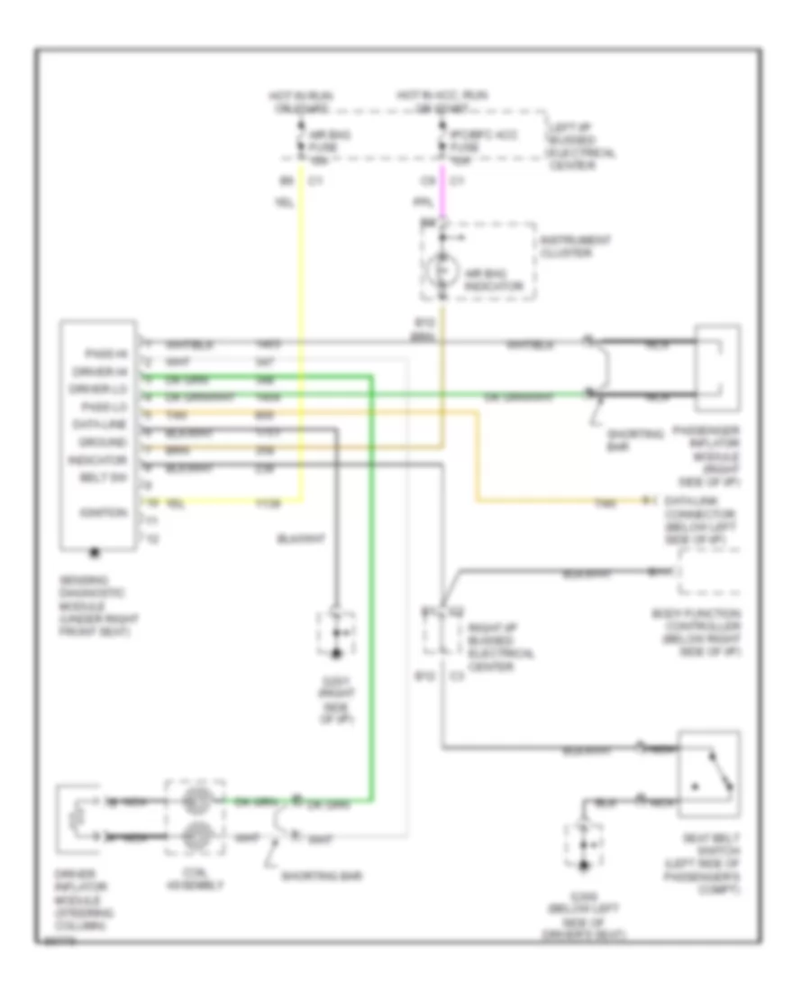
List of elements for Supplemental Restraint Wiring Diagram for Oldsmobile Cutlass 1997:
- Air bag fuse 10a
- Air bag indicator
- B11
- B12
- Belt sw
- Body function controller (below right side of i/p)
- Coil assembly
- Data line
- Data link connector (below left side of i/p)
- Driver hi
- Driver inflator module (steering column)
- Driver lo
- G201 (right side of i/p)
- G300 (below left side of driver's seat)
- Ground
- Hot in acc, run or start
- Hot in run or start
- Ignition
- Indicator
- Instrument cluster
- Ipc/bfc acc fuse 10a
- Left i/p bussed electrical center
- Nca
- Nca b
- Pass hi
- Pass lo
- Passenger inflat0r module (right side of i/p)
- Right i/p bussed electrical center
- Seat belt switch (left side of passenger's compt)
- Sensing diagnostic module (under right front seat)
- Shorting bar
- Tan
 Čeština
 Dansk
Dansk Deutsch
 Ελληνικά
 English
 English
 Español
 Suomi
Suomi Français
 Français
 עברית
עברית Hrvatski
 Magyar
 Italiano
 日本語
日本語 한국어
한국어 Nederlands
 Português
 Português
 Română
 Русский
 Slovenčina
 Slovenščina
 Svenska
 Türkçe
 中文 (中国)
 Polski