ANTI-LOCK BRAKES
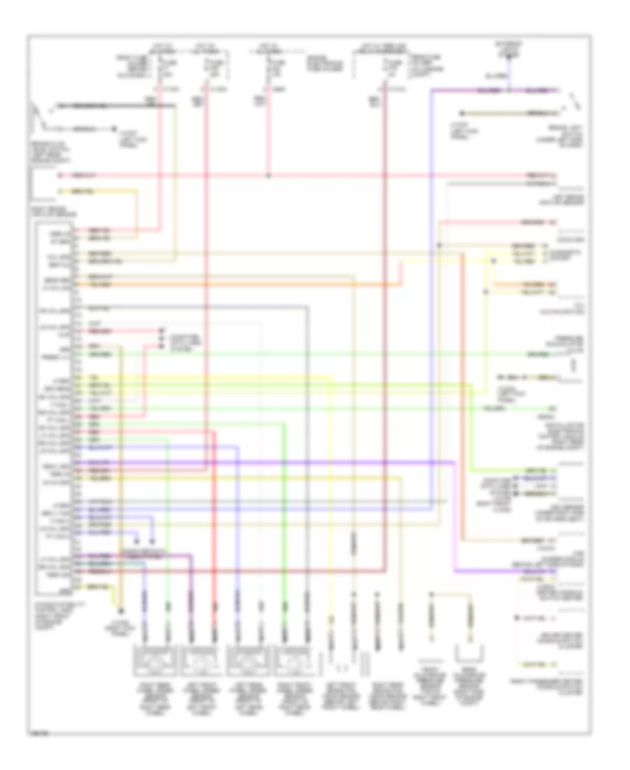
Anti-lock Brakes Wiring Diagram for BMW 650i 2010
List of elements for Anti-lock Brakes Wiring Diagram for BMW 650i 2010:
- Brake fluid level switch (left rear engine compt)
- Brake light switch (under left side of dash)
- Brk fld
- Brk lt sig
- Car access module (behind left side of dash)
- Ccc/m-ask
- Center console switch center
- Computer data lines system
- Computer data lines system x13786 (right front floor)
- Deac. dsc
- Diagnostic socket
- Digital motor electronics control module (right rear of engine compt)
- Driver center console switch cluster
- Dsc sens
- Dsc sensor (under right side of driver's seat)
- Dynamic stability control (dsc) (right front of engine compt)
- Engine electronics fuse holder
- Exterior lights system
- F can h
- F can l
- Fr whl spd
- Front axle brake pressure sensor (top of right front wheel)
- Front fuse holder (behind glove box)
- Front passenger center console switch cluster
- Fuse f06 10a
- Fuse f1 50a
- Fuse f25 25a
- Fuse f78 5a
- Grd
- Hot at all times
- Hot w/ term 30g relay energized
- Left brake air flap sensor
- Left front brake pad wear sensor (behind left front wheel)
- Left front wheel speed sensor (front of left front wheel)
- Left rear wheel speed sensor (front of left rear wheel)
- Lf brk
- Lf whl sig
- Lf whl spd
- Lr wh spd
- Lr whl spd
- Nca
- Press vlv
- Pressure accumulator valve
- Pt can h
- Pt can l
- Rear axle brake pressure sensor (right side of engine compt)
- Rear fuse holder (in luggage compt)
- Red
- Rf whl spd
- Right brake air flap sensor
- Right front wheel speed sensor (front of right rear wheel)
- Right rear brake pad wear sensor (behind right rear wheel)
- Right rear wheel speed sensor (front of right rear wheel)
- Rr whl spd
- Rt brk
- Sens grd
- Tcu (w/o navigation)
- Term 30
- Term 30g
- Whl spd
- Wup
- X10318
- X11001
- X11004
- X11012
- X13782 (right kick panel)
- X13783 (left kick panel)
- X13787 (left kick panel)
- X16919
- X60004
- X8681
 Čeština
 Dansk
Dansk Deutsch
 Ελληνικά
 English
 English
 Español
 Suomi
Suomi Français
 Français
 עברית
עברית Hrvatski
 Magyar
 Italiano
 日本語
日本語 한국어
한국어 Nederlands
 Português
 Português
 Română
 Русский
 Slovenčina
 Slovenščina
 Svenska
 Türkçe
 中文 (中国)
 Polski