COOLING FAN
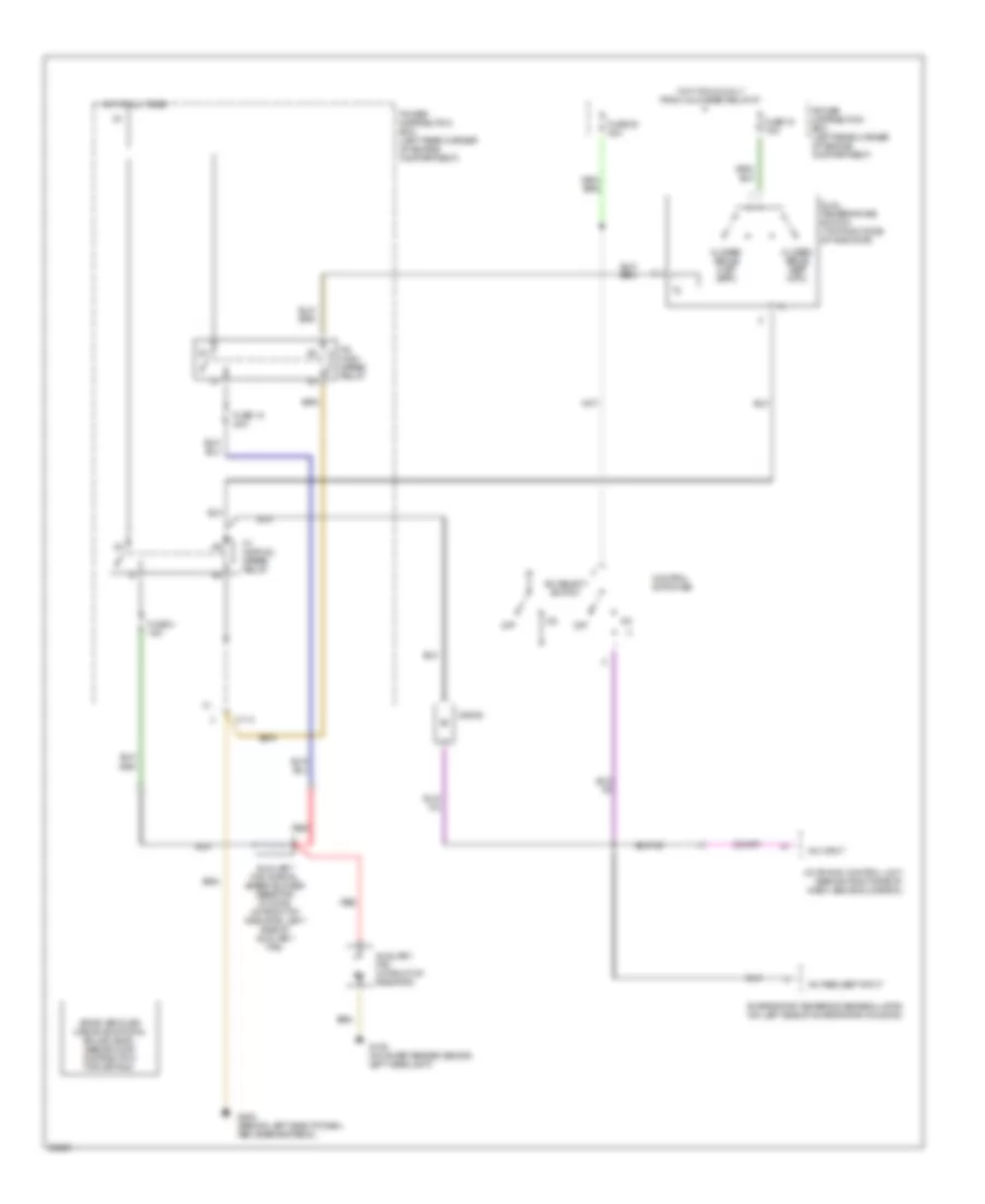
Cooling Fan Wiring Diagram for BMW 325is 1990
List of elements for Cooling Fan Wiring Diagram for BMW 325is 1990:
- A/c input
- A/c request input
- A/c select switch
- Auxiliary fan (in front of radiator)
- Auxiliary fan normal speed blower resistor (6 ohms) (in front of radiator, left side of auxiliary fan)
- C114
- Closed above o 196 f o (91 c)
- Closed above o 210 f o (99 c)
- Control switches
- Diode
- Dual temperature switch (top right side of radiator)
- Evaporator temperature regulator (on left side of evaporator housing)
- Fuse 18 30a
- Fuse 19 7.5a
- Fuse 20 30a
- Fuse 3 15a
- G106 (on inner fender, behind left headlight)
- G202 (behind left side of dash, above brake pedal)
- Hot at all times
- Hot in run only from unloader relay k7
- K1 normal speed relay
- K6 high speed relay
- Motronic control unit (behind right side of dash, above glove box)
- Off
- Power distribution box (left rear corner of engine compartment)
- Red
- Some vehicles use an additional splice (s325). see ground distribution for details.
 Čeština
 Dansk
Dansk Deutsch
 Ελληνικά
 English
 English
 Español
 Suomi
Suomi Français
 Français
 עברית
עברית Hrvatski
 Magyar
 Italiano
 日本語
日本語 한국어
한국어 Nederlands
 Português
 Português
 Română
 Русский
 Slovenčina
 Slovenščina
 Svenska
 Türkçe
 中文 (中国)
 Polski