ANTI-LOCK BRAKES
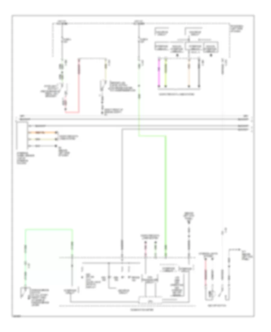
Anti-lock Brakes Wiring Diagram (1 of 3) for Mitsubishi Outlander SE 2013
 https://portal-diagnostov.com/license.html
Automotive Electricians Portal FZCO
Automotive Electricians Portal FZCO
https://portal-diagnostov.com/license.html
https://portal-diagnostov.com/license.html
Automotive Electricians Portal FZCO
Automotive Electricians Portal FZCO
List of elements for Anti-lock Brakes Wiring Diagram (1 of 3) for Mitsubishi Outlander SE 2013:
- Asc-ecu (right rear of engine compt)
- C-129
- C-315
- C-33
- Computer data lines system
- Engine compartment relay box (left side of engine compt)
- Etacs-ecu (left side of dash)
- Fuse 17 10a
- Fusible link 26 40a
- Fusible link 27 30a
- G & yaw rate sensor (under front of center floor console)
- G19 (under left end of dash)
- Hot at all times
- Hydraulic unit
- Left front wheel speed sensor (at left front wheel hub assembly)
- Left rear wheel speed sensor (at left rear wheel hub assembly)
- Motor
- Nca
- Pnk
- Pressure sensor
- Right front wheel speed sensor (at right front wheel hub assembly)
- Right rear wheel speed sensor (at right rear wheel hub assembly)
- Solenoid valve
- Transmissions system
Anti-lock Brakes Wiring Diagram (2 of 3) for Mitsubishi Outlander SE 2013
List of elements for Anti-lock Brakes Wiring Diagram (2 of 3) for Mitsubishi Outlander SE 2013:
- (behind left kick panel) g17
- (right front of engine compt) g1
- Abs ind
- Analog interface circuit
- Asc ind
- Asc off ind (w/o color liquid crystal display)
- Asc off switch
- Brake fluid level switch (on brake master cylinder reservoir)
- Brake ind
- C-22
- C-301
- C-304
- C-312
- C-313
- C-317
- C-32
- Can drive circuit
- Can transceiver circuit
- Combination meter
- Computer data lines system
- Cpu
- Etacs-ecu (left side of dash)
- Fuse 2 15a
- Fuse 9 15a
- G17 (behind left kick panel)
- G6 (behind left side of dash)
- Hot at all times
- Illum
- Interface circuit
- Interior lights system
- Lcd (abs asc operating asc warning asc off brake)
- Led drive circuit
- Parking brake switch (w/ hill start assist (hsa)) (at base of parking brake lever)
- Pnk
- Steering wheel sensor (top of steering column)
- Stoplight switch (above brake pedal, on bracket)
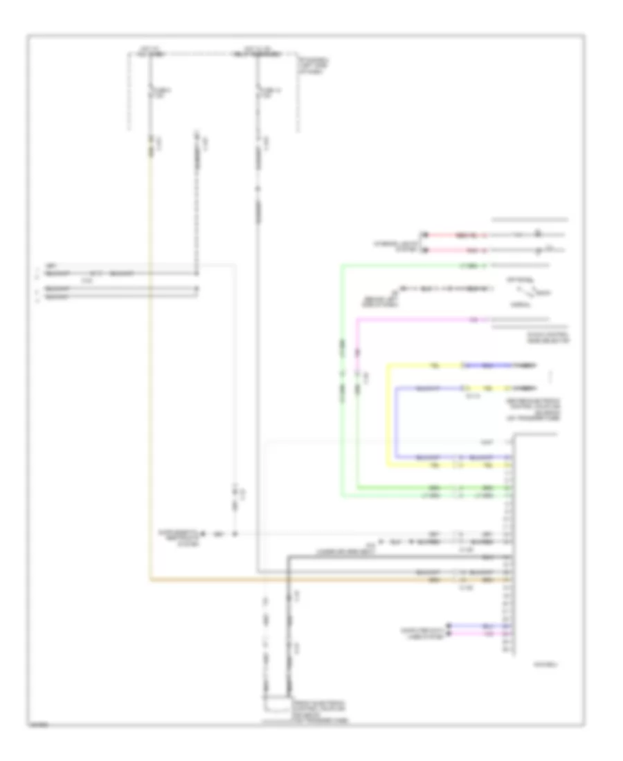
Anti-lock Brakes Wiring Diagram (3 of 3) for Mitsubishi Outlander SE 2013
List of elements for Anti-lock Brakes Wiring Diagram (3 of 3) for Mitsubishi Outlander SE 2013:
- A-13
- Awc-ecu
- C-138
- C-31
- C-311
- C-313
- C-317
- C-32
- C-33
- C-42
- Center electronic control coupling solenoid (on transfer case)
- Computer data lines system
- D-113
- Etacs-ecu (left side of dash)
- Front electronic control coupling solenoid (on transfer case)
- Fuse 12 7.5a
- Fuse 8 7.5a
- G18 (under drivers seat)
- G6 (behind left side of dash)
- Hot at all times
- Hot w/ ig1 relay energized
- Ill
- Interior lights system
- Nca
- Normal
- Off road
- Pnk
- S-awc control mode selector
- Snow

 Čeština
 Dansk
Dansk Deutsch
 Ελληνικά
 English
 English
 Español
 Suomi
Suomi Français
 Français
 עברית
עברית Hrvatski
 Magyar
 Italiano
 日本語
日本語 한국어
한국어 Nederlands
 Português
 Português
 Română
 Русский
 Slovenčina
 Slovenščina
 Svenska
 Türkçe
 中文 (中国)