ANTI-LOCK BRAKES
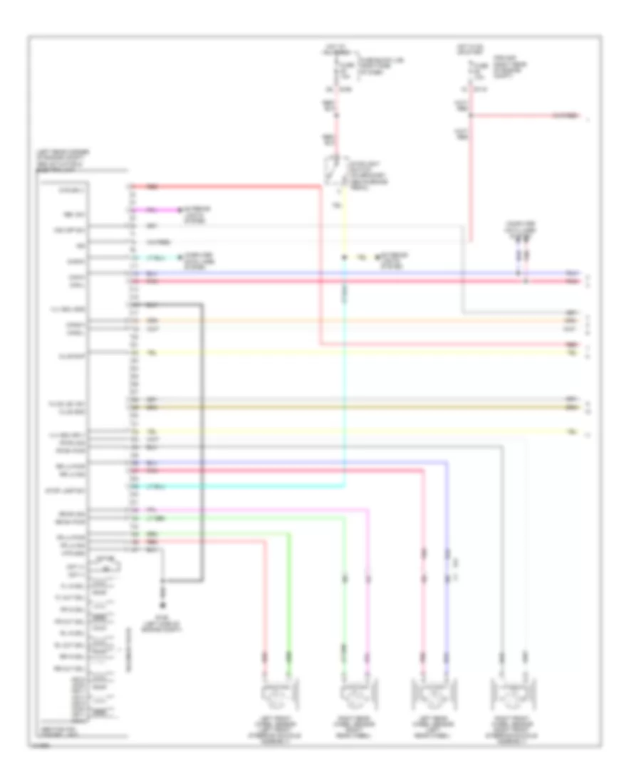
Anti-lock Brakes Wiring Diagram, with Traction Control & Stability Assist with Hill Assist (1 of 2) for Nissan Xterra X 2013
 https://portal-diagnostov.com/license.html
Automotive Electricians Portal FZCO
Automotive Electricians Portal FZCO
https://portal-diagnostov.com/license.html
https://portal-diagnostov.com/license.html
Automotive Electricians Portal FZCO
Automotive Electricians Portal FZCO
List of elements for Anti-lock Brakes Wiring Diagram, with Traction Control & Stability Assist with Hill Assist (1 of 2) for Nissan Xterra X 2013:
- (left rear corner of engine compt) abs actuator & electric unit
- 15c
- 16c
- 17c
- 18c
- Abs/tcs/vdc control unit
- Can-h
- Can-l
- Can2-h
- Can2-l
- Clus gnd
- Clus sup
- Computer data lines system
- Diag-k
- E119
- E126 (left side of engine compt)
- E160
- E41
- Exterior lights system
- Fl in sol
- Fl out sol
- Fluid lev sw
- Fr in sol
- Fr lh pwr
- Fr lh sig
- Fr out sol
- Fr rh pwr
- Fr rh sig
- Fuse 10a
- Fuse block (j/b) (right side of dash)
- Hdc sw
- Hot at all times
- Hot in on or start
- Hsv2 (mc2) hsv1 (mc1) usv2 (mc2) usv1 (mc1)
- Ign
- Ipdm e/r (right rear of engine compt)
- Left front wheel sensor (left front steering knuckle assembly)
- Left rear wheel sensor (left rear wheel)
- Mot (+)
- Mot (-)
- Motor
- Mtr gnd
- Mtr sply
- Pnk
- Red
- Right front wheel sensor (right front steering knuckle assembly)
- Right rear wheel sensor (right rear wheel)
- Rl in sol
- Rl out sol
- Rr in sol
- Rr lh pwr
- Rr lh sig
- Rr out sol
- Rr rh pwr
- Rr rh sig
- Solenoid valve
- Stop lamp relay (in fuse & relay box)
- Stop lp sw
- Stoplight switch (on bracket, above brake pedal)
- Stp lamp on
- Vdc off sw
- Vlv ecu gnd
- Vlv ecu sply
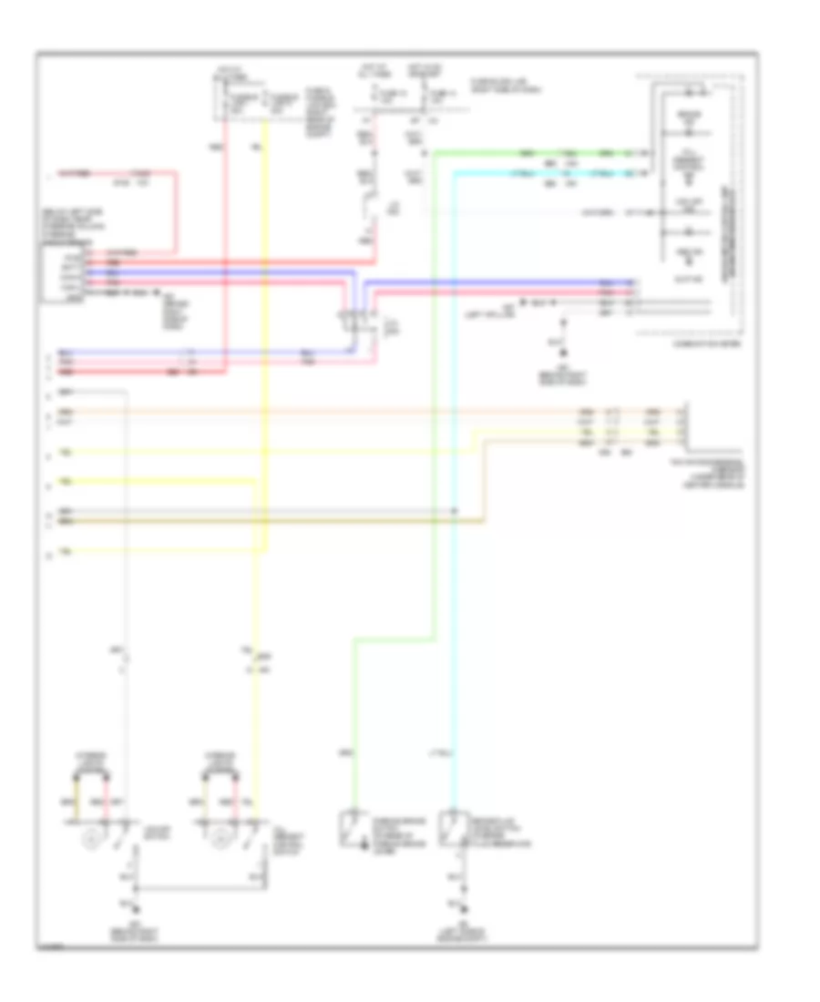
Anti-lock Brakes Wiring Diagram, with Traction Control & Stability Assist with Hill Assist (2 of 2) for Nissan Xterra X 2013
List of elements for Anti-lock Brakes Wiring Diagram, with Traction Control & Stability Assist with Hill Assist (2 of 2) for Nissan Xterra X 2013:
- (below left side of dash, near steering column)
- (w/ information display) unified meter control unit
- 44g
- 68j
- Abs ind
- B40
- B69
- Batt
- Brake fluid level switch (in brake fluid reservoir)
- Brake ind
- Can-h
- Can-l
- Combination meter
- E26
- E34
- E9 (left side of engine compt)
- Fuse & fusible link box (right rear of engine compt)
- Fuse 14 10a
- Fuse 18 10a
- Fuse block (j/b) (right side of dash)
- Fusible link i 30a
- Fusible link n 40a
- Gnd
- Hill descent control ind
- Hill descent control switch
- Hot at all times
- Hot in on or start
- Interior lights system
- J/c m02
- J/c m03
- M31 e152
- M40
- M57 (left a-pillar)
- M61 (behind right side of dash)
- M91
- Parking brake switch (on base of parking brake lever)
- Pnk
- Pwr
- Red
- Slip ind
- Steering angle sensor
- Vdc off ind
- Vdc off switch
- Yaw rate/side/decel g-sensor (under rear of center console)
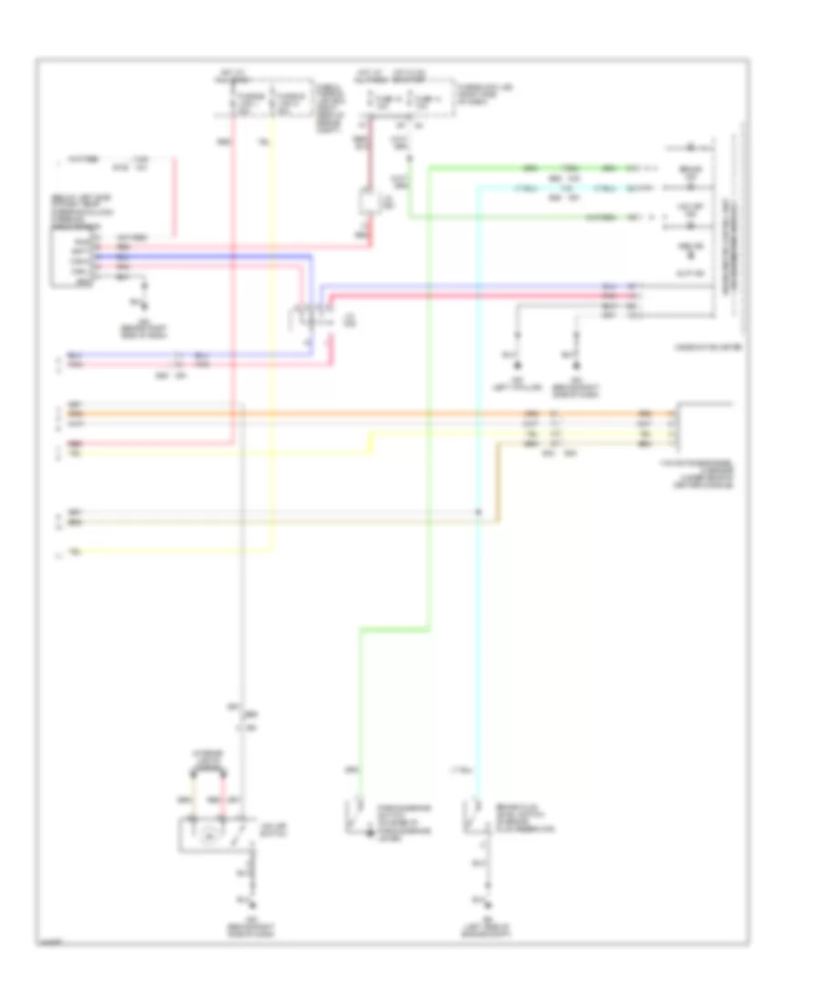
Anti-lock Brakes Wiring Diagram, with Traction Control & Stability Assist, without Hill Assist (1 of 2) for Nissan Xterra X 2013
List of elements for Anti-lock Brakes Wiring Diagram, with Traction Control & Stability Assist, without Hill Assist (1 of 2) for Nissan Xterra X 2013:
- (left rear corner of engine compt) abs actuator & electric unit
- 15c
- 16c
- 17c
- 18c
- Abs/tcs/vdc control unit
- Can-h
- Can-l
- Can2-h
- Can2-l
- Clus gnd
- Clus sup
- Computer data lines system
- Diag-k
- E119
- E126 (left side of engine compt)
- E160
- E41
- Exterior lights system
- Fl in sol
- Fl out sol
- Fluid lev sw
- Fr in sol
- Fr lh pwr
- Fr lh sig
- Fr out sol
- Fr rh pwr
- Fr rh sig
- Fuse 10a
- Fuse block (j/b) (right side of dash)
- Hot at all times
- Hot in on or start
- Hsv2 (mc2) hsv1 (mc1) usv2 (mc2) usv1 (mc1)
- Ign
- Ipdm e/r (right rear of engine compt)
- Left front wheel sensor (left front steering knuckle assembly)
- Left rear wheel sensor (left rear wheel)
- Mot (+)
- Mot (-)
- Motor
- Mtr gnd
- Mtr sply
- Pnk
- Red
- Rev sw
- Right front wheel sensor (right front steering knuckle assembly)
- Right rear wheel sensor (right rear wheel)
- Rl in sol
- Rl out sol
- Rr in sol
- Rr lh pwr
- Rr lh sig
- Rr out sol
- Rr rh pwr
- Rr rh sig
- Solenoid valve
- Stop lamp sw
- Stoplight switch (on bracket, above brake pedal)
- Vdc off sw
- Vlv ecu gnd
- Vlv ecu sply
Anti-lock Brakes Wiring Diagram, with Traction Control & Stability Assist, without Hill Assist (2 of 2) for Nissan Xterra X 2013
List of elements for Anti-lock Brakes Wiring Diagram, with Traction Control & Stability Assist, without Hill Assist (2 of 2) for Nissan Xterra X 2013:
- (below left side of dash, near steering column) steering angle sensor
- 44g
- 68j
- Abs ind
- B40
- B69
- Batt
- Brake fluid level switch (in brake fluid reservoir)
- Brake ind
- Can-h
- Can-l
- Combination meter
- E152 m31
- E26
- E34
- E9 (left side of engine compt)
- Fuse & fusible link box (right rear of engine compt)
- Fuse 14 10a
- Fuse 18 10a
- Fuse block (j/b) (right side of dash)
- Fusible link l 30a
- Fusible link n 40a
- Gnd
- Hot at all times
- Hot in on or start
- Interior lights system
- J/c m02
- J/c m03
- M40
- M57 (left a-pillar)
- M61 (behind right side of dash)
- M91
- M91 e26
- Parking brake switch (on base of parking brake lever)
- Pnk
- Pwr
- Red
- Slip ind
- Unified meter control unit (w/ information display)
- Vdc off ind
- Vdc off switch
- Yaw rate/side/decel g sensor (under rear of center console)

 Čeština
 Dansk
Dansk Deutsch
 Ελληνικά
 English
 English
 Español
 Suomi
Suomi Français
 Français
 עברית
עברית Hrvatski
 Magyar
 Italiano
 日本語
日本語 한국어
한국어 Nederlands
 Português
 Português
 Română
 Русский
 Slovenčina
 Slovenščina
 Svenska
 Türkçe
 中文 (中国)