CRUISE CONTROL
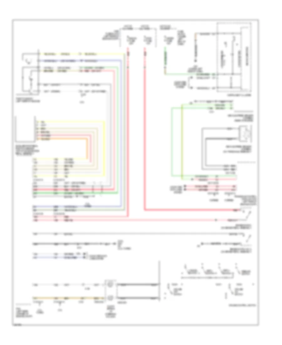
Cruise Control Wiring Diagram for Mazda CX-7 s Touring 2011
List of elements for Cruise Control Wiring Diagram for Mazda CX-7 s Touring 2011:
- (2.5l) g22 g2 (2.3l turbo)
- (or red)
- 0140-01a
- 0140-01b
- 0140-201a
- 0140-201b
- 0517-01b
- 0517-201a
- 0517-201b
- 0922-202
- 0922-203
- 1ab
- 1ac
- 1ae
- 1af
- 1ai
- 1aj
- 1am
- 1an
- 1ao
- 1aq
- 1av
- 1ba
- 1be
- 1bh
- 2.3l turbo
- 2.5l
- 2aj
- 2ak
- 2al
- 2an
- 2ao
- 2ar
- 2be
- 2bf
- 5 speed
- 6 speed
- A14
- Accelerator pedal position sensor (top of accelerator pedal assembly)
- B19
- B20
- Brake switch (on brake pedal assembly)
- Brake switch no. 2 (on brake pedal assembly)
- C-02
- C-06
- C-09
- C-21
- Cancel switch
- Clock spring (in steering column)
- Computer data lines system
- Cruise control switch
- Cruise main ind
- Cruise off switch
- Cruise on switch
- Cruise set ind
- Eng b+ fuse 25a
- Fuse block (under left end of dash)
- G10 (under left side of dash)
- Hot at all times
- Hot in on or start
- Instrument cluster
- Main fuse block (left rear of engine compt)
- Meter fuse 15a
- Microcomputer
- Nca
- Pcm (left rear corner of engine compt)
- Red
- Resume switch
- Set(+) switch
- Set(-) switch
- Stop fuse 10a
- Throttle body (left rear of engine)
- Transaxle control module (tcm) (left side of engine compt)
- Vehicle speed sensor (5 speed) (rear of engine)
- Vehicle speed sensor (6 speed) (on transaxle assembly)
 Čeština
 Dansk
Dansk Deutsch
 Ελληνικά
 English
 English
 Español
 Suomi
Suomi Français
 Français
 עברית
עברית Hrvatski
 Magyar
 Italiano
 日本語
日本語 한국어
한국어 Nederlands
 Português
 Português
 Română
 Русский
 Slovenčina
 Slovenščina
 Svenska
 Türkçe
 中文 (中国)
 Polski