TRANSMISSION
A/T Wiring Diagram, Evolution for Mitsubishi Lancer ES 2014
 https://portal-diagnostov.com/license.html
Automotive Electricians Portal FZCO
Automotive Electricians Portal FZCO
https://portal-diagnostov.com/license.html
https://portal-diagnostov.com/license.html
Automotive Electricians Portal FZCO
Automotive Electricians Portal FZCO
List of elements for A/T Wiring Diagram, Evolution for Mitsubishi Lancer ES 2014:
- A-13
- Acc relay 2 energized
- C-131
- C-27
- C-315
- C-317
- C-35
- Can transceiver circuit
- Combination meter
- Computer data lines system
- Cpu
- Engine compartment relay box (left side of engine compt)
- Etacs-ecu (on rear of junction block, behind left end of dash)
- Fuse 10a
- Fuse 15a
- Fuse 20a
- Fuse 7.5a
- G19 (left side of engine compt)
- G3 (left rear of engine)
- G4 (behind right kick panel)
- G6 (behind center of dash)
- Hot at all times
- Hot w/
- Ig1 relay energized
- Ill
- Interface circuit
- Interior
- Lcd (shift position normal sport s-sport)
- Lights system
- Low side switch
- Manual
- Mode (+)
- Mode (-)
- Nca
- Paddle shift switch
- Pnk
- Shift lever (center console)
- Shift lever position indicator panel
- Shift lever position sensor (p, r, n, d, m, +, -)
- Transaxle assembly (transmission assembly)
- Twin clutch sport shift transaxle control module switch
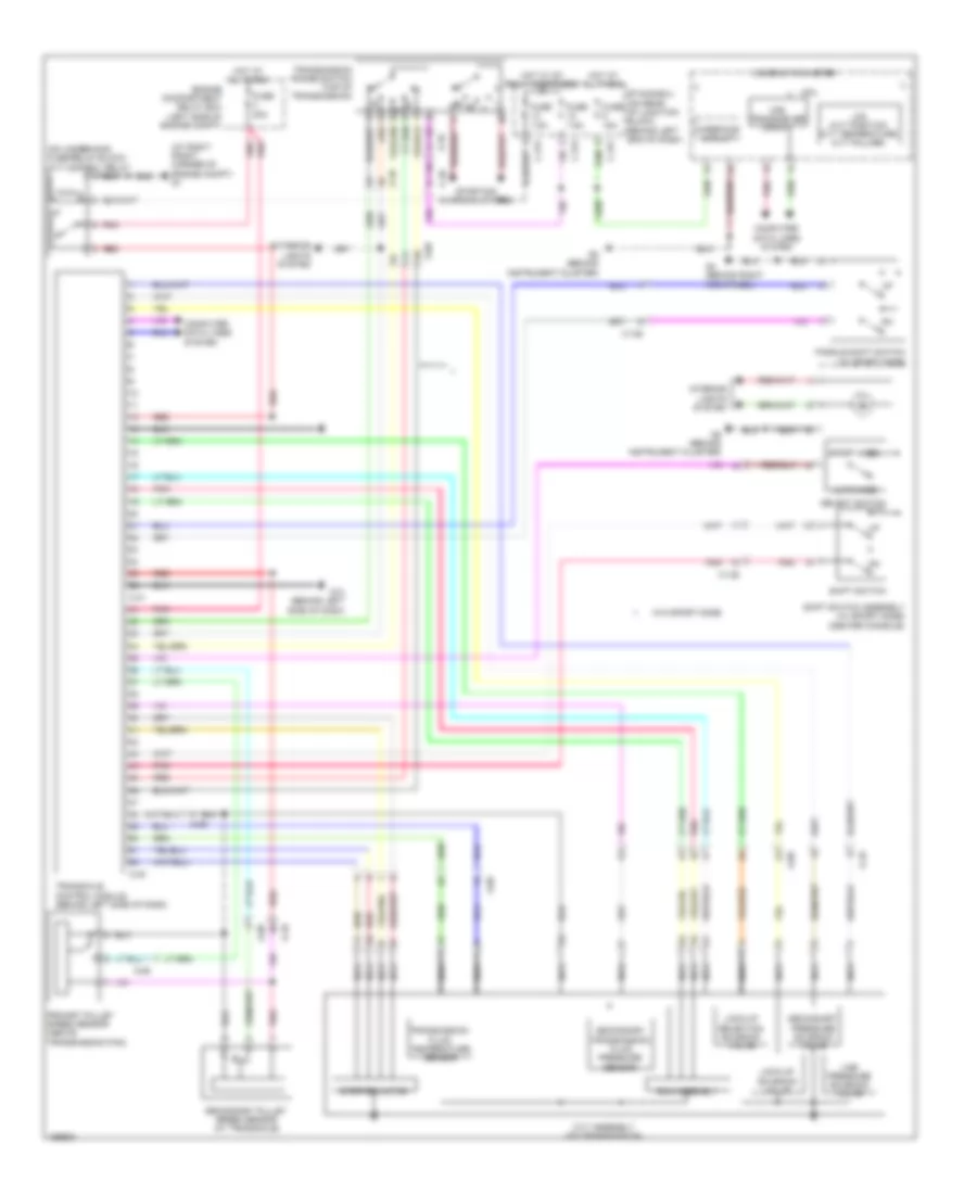
A/T Wiring Diagram, Except Evolution CVT for Mitsubishi Lancer ES 2014
List of elements for A/T Wiring Diagram, Except Evolution CVT for Mitsubishi Lancer ES 2014:
- (at right front corner of engine compt) g1
- (center console)
- (on underhood fuse/relay block) cvt control relay
- A-09
- A-10
- Auto mode
- C-128
- C-313
- C-317
- C-39
- C-40
- C-41
- Can transceiver circuit
- Combination meter
- Computer data lines system
- Cpu
- Cvt assembly (on transmission)
- Engine compartment relay box (left side of engine compt)
- Etacs-ecu (on rear of junction block, behind left end of dash)
- Exterior lights system
- Fuse 15a
- Fuse 20a
- Fuse 7.5a
- G13 (behind left side of dash)
- G4 (behind right kick panel)
- G5 (behind instrument cluster)
- Hot at all times
- Hot w/ ig1 relay energized
- Ill
- Interface circuit
- Interior lights system
- Lcd (cvt position cvt temperature cvt failure)
- Line pressure solenoid valve
- Lock-up selection solenoid valve
- Lock-up solenoid valve
- Nca
- Paddle shift switch (w/ sport mode)
- Pnk
- Primary pulley speed sensor (above transmission pan)
- Red
- Rom-assembly
- Secondary pressure solenoid valve
- Secondary pulley speed sensor (at transaxle)
- Secondary transmission fluid pressure sensor
- Select switch
- Shift switch
- Shift switch assembly (w/ sport mode)
- Sport mode
- Starting/ charging system
- Stepper motor
- Transaxle control module (behind left side of dash)
- Transmission fluid temperature sensor
- Transmission range switch (top of transmission)
- W/o sport mode
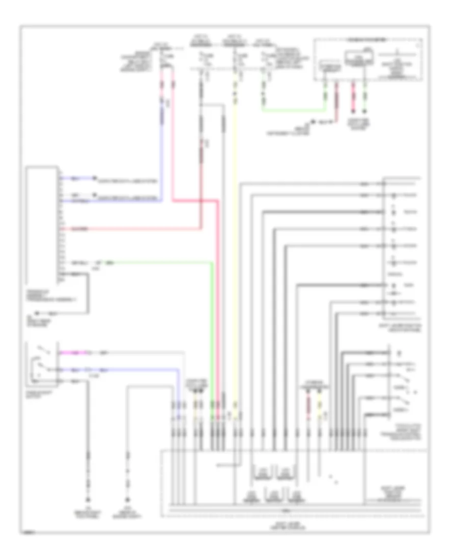
A/T Wiring Diagram, Except Evolution TC-SST for Mitsubishi Lancer ES 2014
List of elements for A/T Wiring Diagram, Except Evolution TC-SST for Mitsubishi Lancer ES 2014:
- A-54
- Acc relay 2 energized
- C-128
- C-315
- C-317
- C-49
- C-54
- Can transceiver circuit
- Combination meter
- Computer data lines system
- Cpu
- Engine compartment relay box (left side of engine compt)
- Etacs-ecu (on rear of junction block, behind left end of dash)
- Fuse 10a
- Fuse 15a
- Fuse 20a
- Fuse 7.5a
- G16 (rear of engine compt)
- G2 (right rear of engine)
- G4 (behind right kick panel)
- G5 (behind instrument cluster)
- Hot at all times
- Hot w/
- Ig1 relay energized
- Ill
- Interface circuit
- Interior
- Lcd (shift position normal sport s-sport)
- Lights system
- Low side switch
- Manual
- Mode (+)
- Mode (-)
- Nca
- Paddle shift switch
- Pnk
- Shift lever (center console)
- Shift lever position indicator panel
- Shift lever position sensor (p, r, n, d, m, +, -)
- Transaxle assembly (transmission assembly)
- Twin clutch sport shift transaxle control module switch
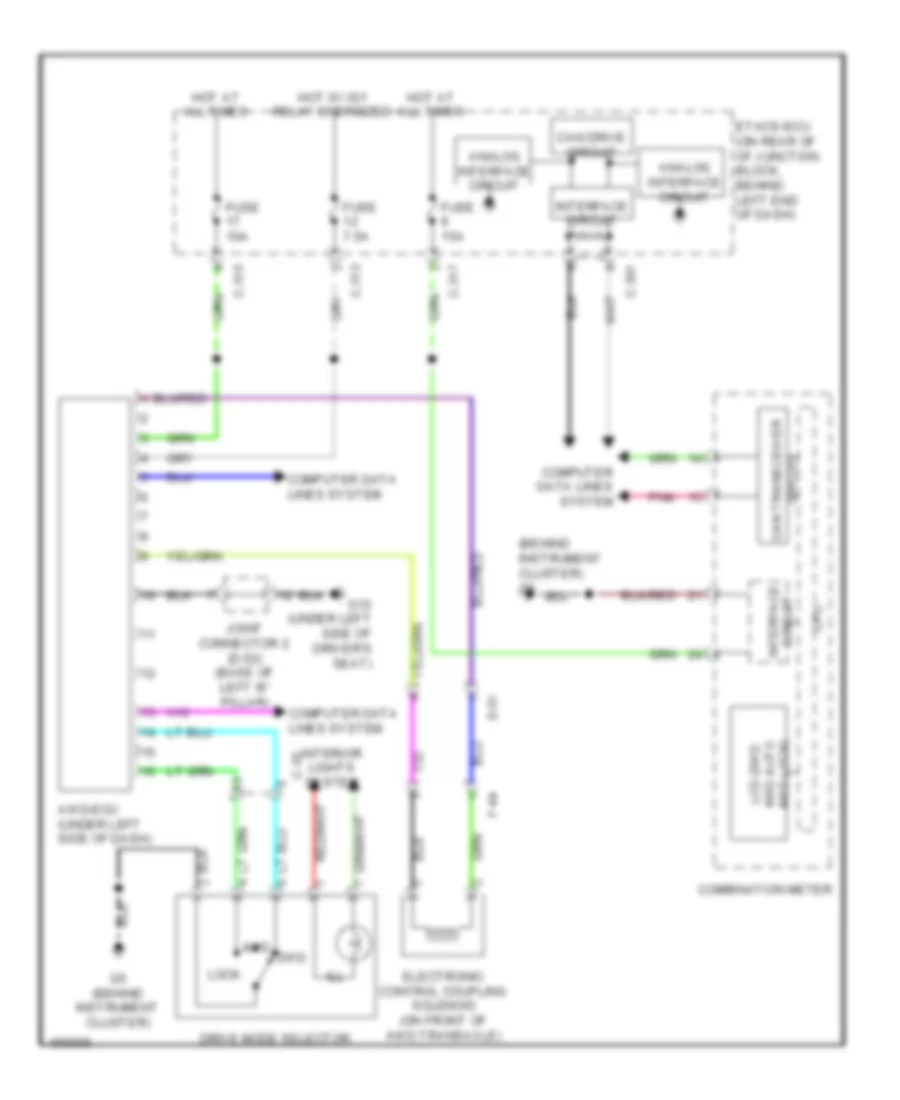
AWD Wiring Diagram for Mitsubishi Lancer ES 2014
List of elements for AWD Wiring Diagram for Mitsubishi Lancer ES 2014:
- (behind instrument cluster) g5
- 2wd
- 4wd
- Analog interface circuit
- Awd-ecu (under left side of dash)
- C-301
- C-313
- C-315
- C-317
- C-35
- Can drive circuit
- Circuit can transceiver
- Circuit interface
- Combination meter
- Computer data lines system
- Cpu
- D-51
- Drive mode selector
- Electronic control coupling solenoid (on front of awd transaxle)
- Etacs-ecu (on rear of of junction block, behind left end of dash)
- F-44
- Fuse 10a
- Fuse 15a
- Fuse 7.5a
- G12 (under left side of driver's seat)
- G5 (behind instrument cluster)
- Hot at all times
- Hot w/ ig1 relay energized
- Ill
- Interface circuit
- Interior lights system
- Joint connector 2 (d-52) (base of left 'b" pillar)
- Lcd (2wd 4wd auto 4wd lock)
- Lock
- Pnk

 Čeština
 Dansk
Dansk Deutsch
 Ελληνικά
 English
 English
 Español
 Suomi
Suomi Français
 Français
 עברית
עברית Hrvatski
 Magyar
 Italiano
 日本語
日本語 한국어
한국어 Nederlands
 Português
 Português
 Română
 Русский
 Slovenčina
 Slovenščina
 Svenska
 Türkçe
 中文 (中国)