WARNING SYSTEMS
Warning Systems Wiring Diagram for Nissan Armada SE 2007
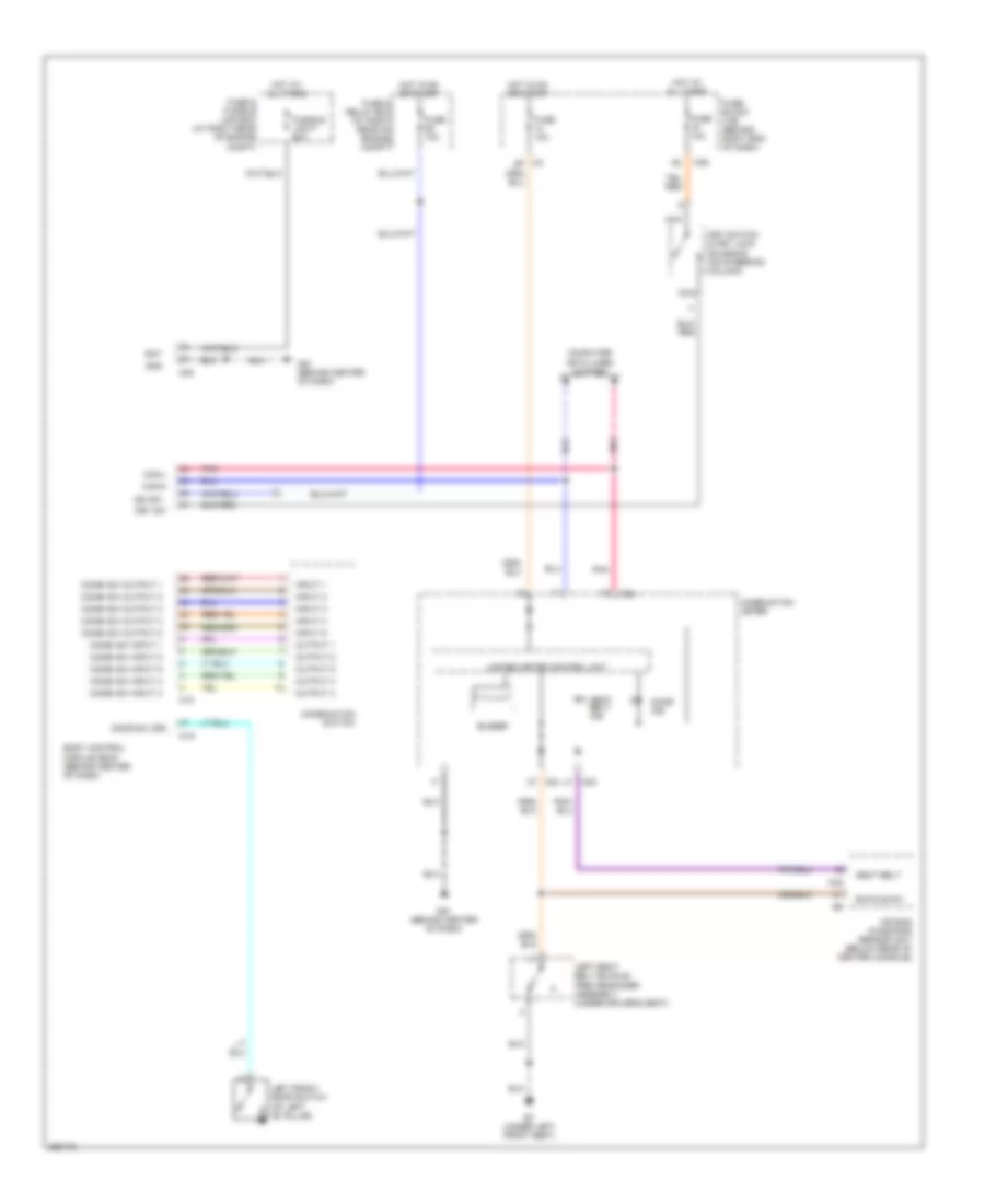
List of elements for Warning Systems Wiring Diagram for Nissan Armada SE 2007:
- Air bag diagnosis sensor unit (below rear of center console)
- B7 (under left front seat)
- Bat
- Body control module (bcm) (behind center of dash)
- Buckle sw
- Buzzer
- Can-h
- Can-l
- Combi sw input 1
- Combi sw input 2
- Combi sw input 3
- Combi sw input 4
- Combi sw input 5
- Combi sw output 1
- Combi sw output 2
- Combi sw output 3
- Combi sw output 4
- Combi sw output 5
- Combination meter
- Combination switch
- Computer data lines system
- Door ind
- Door sw (dr)
- Fuse & fusible link box (at right rear of engine compt)
- Fuse & relay box (at right rear of engine compt)
- Fuse 10a
- Fuse block (j/b) (behind right end of dash)
- Fusible link f 50a
- Gnd
- Hot at all times
- Hot in on or start
- Ign sw
- Input 1
- Input 2
- Input 3
- Input 4
- Input 5
- Key sw
- Key switch & key lock solenoid (on steering column)
- Left front door switch (at left "b" pillar)
- Left seat belt buckle pre-tensioner assembly (under driver's seat)
- M18
- M19
- M20
- M23
- M24
- M35
- M39
- M61 (behind center of dash)
- Nca
- Output 1
- Output 2
- Output 3
- Output 4
- Output 5
- Pnk
- Seat belt
- Seat belt ind
- Unified meter control unit
 Čeština
 Dansk
Dansk Deutsch
 Ελληνικά
 English
 English
 Español
 Suomi
Suomi Français
 Français
 עברית
עברית Hrvatski
 Magyar
 Italiano
 日本語
日本語 한국어
한국어 Nederlands
 Português
 Português
 Română
 Русский
 Slovenčina
 Slovenščina
 Svenska
 Türkçe
 中文 (中国)
 Polski