COOLING FAN
Cooling Fan Wiring Diagram for Mercedes-Benz ML550 2013
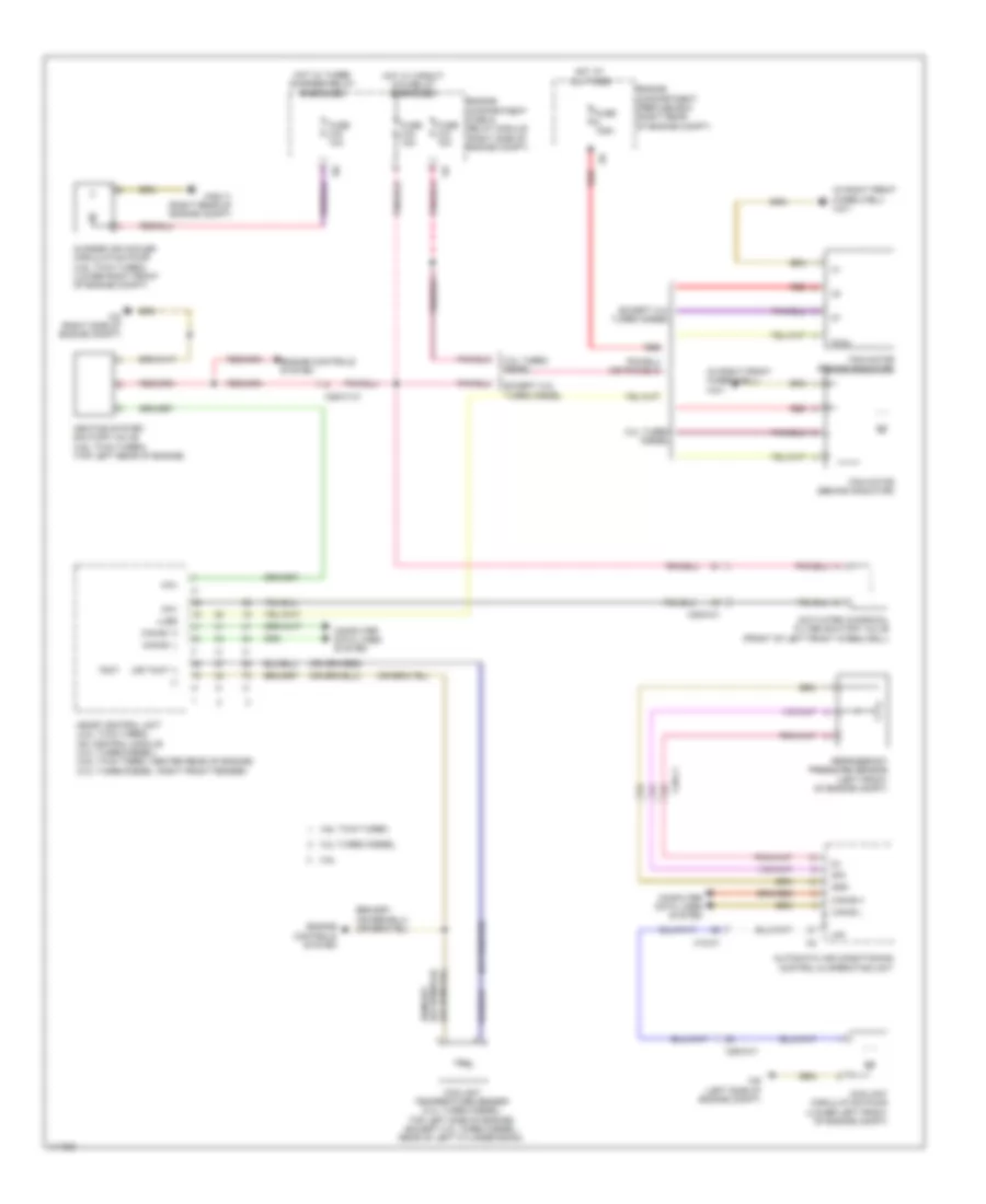
List of elements for Cooling Fan Wiring Diagram for Mercedes-Benz ML550 2013:
- (-)
- (in right front wheelwell) w2/1
- (or tmot 1)
- 3.0l turbo diesel
- 3.5l
- 4.6l twin turbo
- Aav
- Activated charcoal filter shutoff valve (front of left front wheelwell)
- Automatic air conditioning control & operating unit
- Can-b h
- Can-b l
- Can-e1 h
- Can-e1 l
- Charge air cooler circulation pump (4.6l twin turbo) (lower right front of engine compt)
- Computer data lines system
- Coolant circulation pump (lower left front of engine compt)
- Coolant temperature sensor (3.0l turbo diesel: top left side of engine) (except 3.0l turbo diesel: rear of left cylinder bank)
- Engine compartment fuse & relay module (right side of engine compt)
- Engine compartment prefuse box (right rear of engine compt)
- Engine controls system
- Except 3.0l turbo diesel
- Fan motor (behind radiator)
- Fuse 10a
- Fuse 125a
- Fuse 15a
- Gnd
- Hav
- Heating system shutoff valve (4.6l twin turbo) (top left rear of engine)
- Hot at all times
- Hot w/ circuit 87m relay energized
- Hot w/ turbo charger relay energized
- Lues
- Me-sfi control unit (4.6l twin turbo) cdi control module (3.0l turbo diesel) (4.6l twin turbo: center rear of engine) (3.0l turbo diesel: right front fender)
- Pwm
- Red
- Refrigerant pressure sensor (left front of engine compt)
- Sig
- Tmot
- W2 (right side of engine compt)
- W52/11 (right rear of engine compt)
- W9 (left side of engine compt)
- X18-c1
- X25/2-c1
- X26/31-c1
 Čeština
 Dansk
Dansk Deutsch
 Ελληνικά
 English
 English
 Español
 Suomi
Suomi Français
 Français
 עברית
עברית Hrvatski
 Magyar
 Italiano
 日本語
日本語 한국어
한국어 Nederlands
 Português
 Português
 Română
 Русский
 Slovenčina
 Slovenščina
 Svenska
 Türkçe
 中文 (中国)
 Polski