AIR CONDITIONING
2.2L
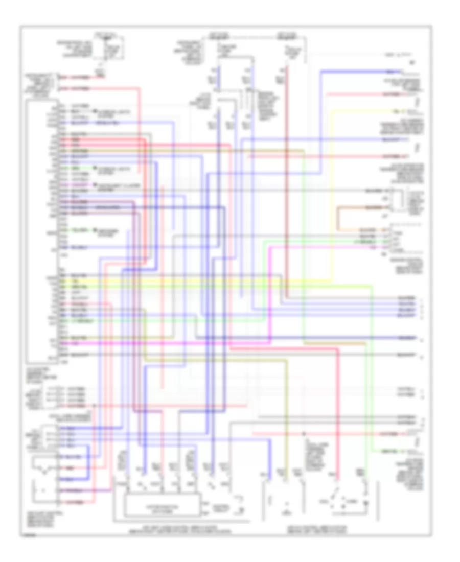
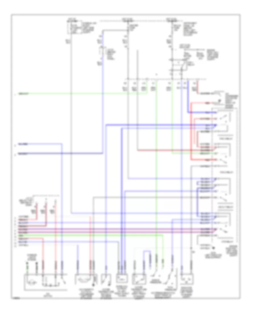
2.2L CNG, Manual A/C Wiring Diagram (1 of 2) for Toyota Camry CE 2000
 https://portal-diagnostov.com/license.html
Automotive Electricians Portal FZCO
Automotive Electricians Portal FZCO
https://portal-diagnostov.com/license.html
https://portal-diagnostov.com/license.html
Automotive Electricians Portal FZCO
Automotive Electricians Portal FZCO
List of elements for 2.2L CNG, Manual A/C Wiring Diagram (1 of 2) for Toyota Camry CE 2000:
- (cowl wire harn, above glove box)
- (cowl wire harn, i14: right side of dash, i8: center of dash)
- (cowl wire harn, i3: right side of dash, i8: center of dash)
- (cowl wire harn, i3: right side of dash, i9: center of dash)
- 2.2l
- 2.2l cng
- A/c fuse 10a
- A/c switch
- Air inlet control servo motor
- Air inlet controls
- Air vent controls
- Air vent mode control servo motor (behind right center of dash, on blower housing)
- B/l
- Blower resistor (behind right center of dash)
- Blower motor (behind right side of dash)
- Blower switch
- Control circuit
- Def
- Ecu-b fuse 10a
- Engine room j/b 2 (left side of engine compt)
- Engine room r/b 1 (left side of engine compt)
- F/d
- Face
- Foot
- Fresh
- G202 (left instrument panel brace)
- Gnd
- H15 h13
- H9 h7
- Heater control switch
- Hot in on
- I14
- I3 i6
- I8 i3
- I9 i3
- Instrument panel j/b (behind dash, left of steering column)
- Interior lights system
- J/c 11 j/c 9 (behind center of dash)
- J/c 12 (below top center of dash)
- Motor position switches
- Off
- Or start
- Recirc
- Red
- Tmc
- Tmmk
- V10
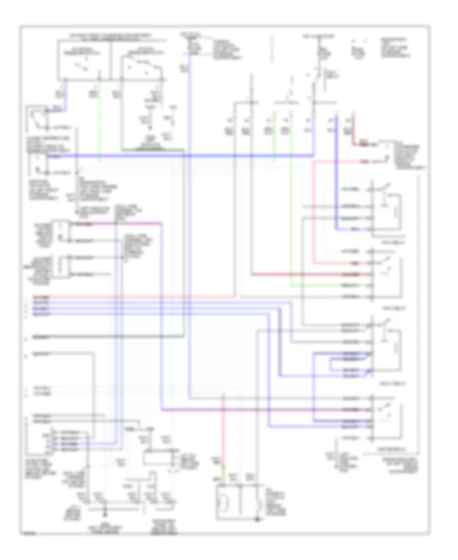
2.2L CNG, Manual A/C Wiring Diagram (2 of 2) for Toyota Camry CE 2000
List of elements for 2.2L CNG, Manual A/C Wiring Diagram (2 of 2) for Toyota Camry CE 2000:
- 2.2l
- 2.2l cng
- 2.2l w/ engine immobilizer
- 2.2l w/o engine immobilizer
- A/c condenser fan motor (right front of engine compt)
- A/c evaporator temperature sensor (on evaporator)
- A/c magnetic clutch & lock sensor (left side of engine)
- A/c pressure switch (right front of engine compt)
- A/cs
- Acmg
- Cds fuse 30a
- Dual pressure
- E10
- E11
- E4 (engine harn, e2: right front corner of engine compt, e4: left side of engine compt)
- Ecu-ig fuse 15a
- Engine control module (behind right side of dash)
- Engine room j/b 2 (left side of engine compt)
- Engine room r/b 1 (left side of engine compt)
- Fan 1 relay
- Fan 2 relay
- Fan 3 relay
- Fusible link block (left side of engine compt)
- G108 (left radiator side support)
- G131 (on intake manifold)
- Heater fuse 10a
- Hot at all times
- Hot in on
- Hot in on or start
- Htr fusible link 50a
- Htr relay
- Instrument panel j/b (behind dash, left of steering column)
- J/c 23 j/c 20 (behind right side of dash)
- J/c 32 j/c 30 (behind upper right end of dash)
- J/c 8 j/c 7 (behind left side of dash)
- Lcki
- Lock
- Mg clt relay
- Or start
- Prs
- Radiator fan motor (left front of engine compt)
- Rdi fuse 30a
- Red
- Single pressure
- Thr
- Water temperature switch 1 (right front of engine compt)
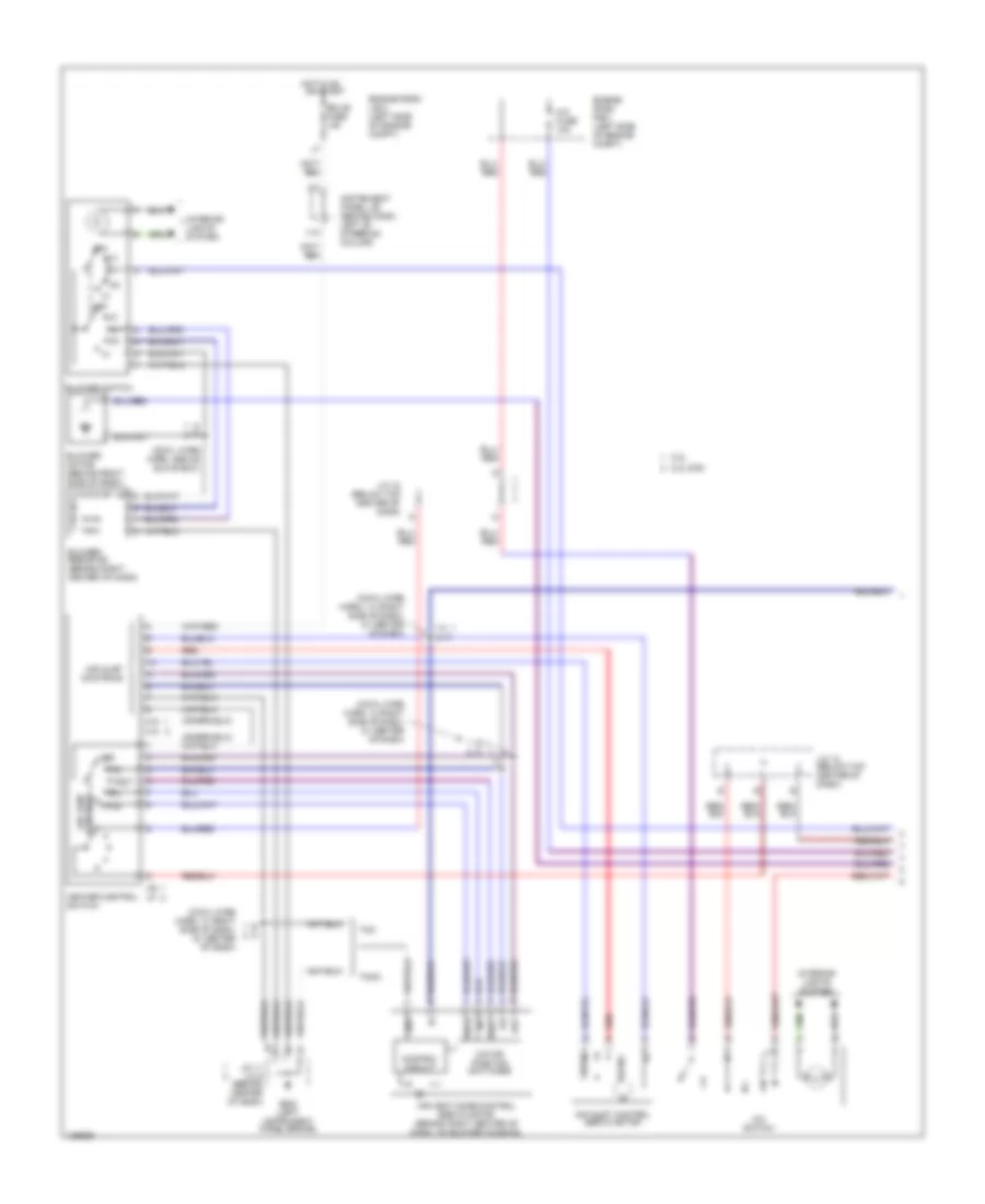
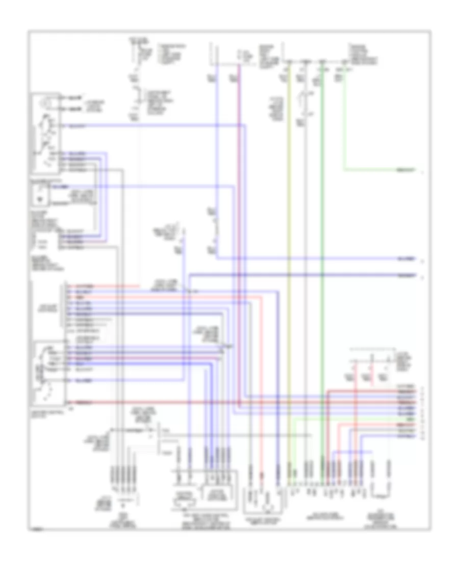
2.2L, Automatic A/C Wiring Diagram (1 of 2) for Toyota Camry CE 2000
List of elements for 2.2L, Automatic A/C Wiring Diagram (1 of 2) for Toyota Camry CE 2000:
- A/c ambient temperature sensor (on front center of engine compartment)
- A/c control assembly (behind center of dash)
- A/c evaporator temperature sensor (behind right side of dash, on evaporator)
- A/c room temperature sensor (behind left side of dash, right side of steering column)
- A/c solar sensor (top left side of dash)
- A10
- A11
- A12
- A13
- A14
- A15
- A16
- A17
- A18
- A19
- A20
- A21
- A22
- A23
- A24
- A25
- A26
- A34
- A35
- Ac1
- Act
- Aif
- Air
- Air inlet control servo motor (behind right side of dash)
- Air mix control servo motor (behind left center of dash)
- Air vent mode control servo motor (behind right center of dash, on blower housing)
- Amc
- Amh
- B/l
- B10
- B11
- B12
- B13
- B14
- B15
- B16
- Blw
- Control circuit
- Cool
- Def
- Defogger system
- Ecu-b fuse 10a
- Ecu-ig fuse 15a
- Engine control module (behind right side of dash)
- Engine room j/b 2 (on left side of engine compart- ment)
- Engine room j/b 2 (on left side of engine compartment)
- F/d
- Face
- Foot
- Gnd
- Heater fuse 10a
- Hot at all times
- Hot in on or start
- I10 (cowl wire harness, above glove box)
- Ig+
- Ign
- Illum
- Instrument cluster system
- Instrument panel j/b (behind dash, left of steering column)
- Interior lights system
- J/c 1 (behind left kick panel)
- J/c 27 & j/c 28 (behind right side of dash)
- J/c 29 (behind right side of dash)
- J/c 32 (behind right kick panel)
- J27
- J28
- Lock
- Mgcr
- Motor position switches
- Pnk
- Psw
- Rdfg
- Red
- Spd
- Tach
- Tam
- Thwo
- Tpi
- V10
- Warm
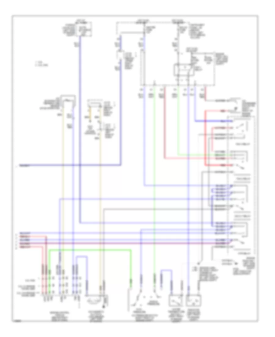
2.2L, Automatic A/C Wiring Diagram (2 of 2) for Toyota Camry CE 2000
List of elements for 2.2L, Automatic A/C Wiring Diagram (2 of 2) for Toyota Camry CE 2000:
- (cowl wire harness, left side of dash, right of steering column) i8
- (cowl wire harness, top center of dash) i7
- (left radiator side support) g108
- (on right front of engine compartment) a/c triple pressure switch
- A/c blower motor linear controller (behind center of dash)
- A/c condenser fan motor (on right front of engine compartment)
- A/c dual pressure switch
- A/c magnetic clutch & lock sensor (left side of engine)
- A/c single pressure switch
- Blower motor (behind right side of dash)
- Blower resistor (behind right center of dash, on blower housing)
- Cds fuse 30a
- Compartment)
- Engine room j/b 2 (on left side of engine compartment)
- Engine room r/b 1 (on left side of engine compartment)
- Fan 1 relay
- Fan 2 relay
- Fan 3 relay
- Fusible link block (on left side of engine compartment)
- G108 (left radiator side support)
- G202 (left instrument panel brace)
- Gnd
- Heater relay
- Hot at all times
- Hot in or start
- Htr fuse 50a
- I7 (cowl wire harness, top center of dash)
- Instrument panel j/b (behind left side of dash)
- J/c 11 (behind center of dash)
- J/c 7 & 8 (behind left side of dash)
- J7 a
- J8 a
- Mg clt relay
- Radiator fan motor (on left front of engine compartment)
- Rdi fuse 30a
- Red
- Tmc
- Tmmk
- Water temperature switch 1 (on right front of engine compartment)
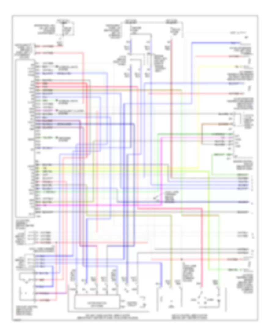
2.2L, Manual A/C Wiring Diagram (1 of 2) for Toyota Camry CE 2000
List of elements for 2.2L, Manual A/C Wiring Diagram (1 of 2) for Toyota Camry CE 2000:
- (cowl wire harn, above glove box)
- (cowl wire harn, i14: right side of dash, i8: center of dash)
- (cowl wire harn, i3: right side of dash, i8: center of dash)
- (cowl wire harn, i3: right side of dash, i9: center of dash)
- 2.2l
- 2.2l cng
- A/c fuse 10a
- A/c switch
- Air inlet control servo motor
- Air inlet controls
- Air vent controls
- Air vent mode control servo motor (behind right center of dash, on blower housing)
- B/l
- Blower resistor (behind right center of dash)
- Blower motor (behind right side of dash)
- Blower switch
- Control circuit
- Def
- Ecu-b fuse 10a
- Engine room j/b 2 (left side of engine compt)
- Engine room r/b 1 (left side of engine compt)
- F/d
- Face
- Foot
- Fresh
- G202 (left instrument panel brace)
- Gnd
- H15 h13
- H9 h7
- Heater control switch
- Hot in on
- I14
- I3 i6
- I8 i3
- I9 i3
- Instrument panel j/b (behind dash, left of steering column)
- Interior lights system
- J/c 11 j/c 9 (behind center of dash)
- J/c 12 (below top center of dash)
- Motor position switches
- Off
- Or start
- Recirc
- Red
- Tmc
- Tmmk
- V10
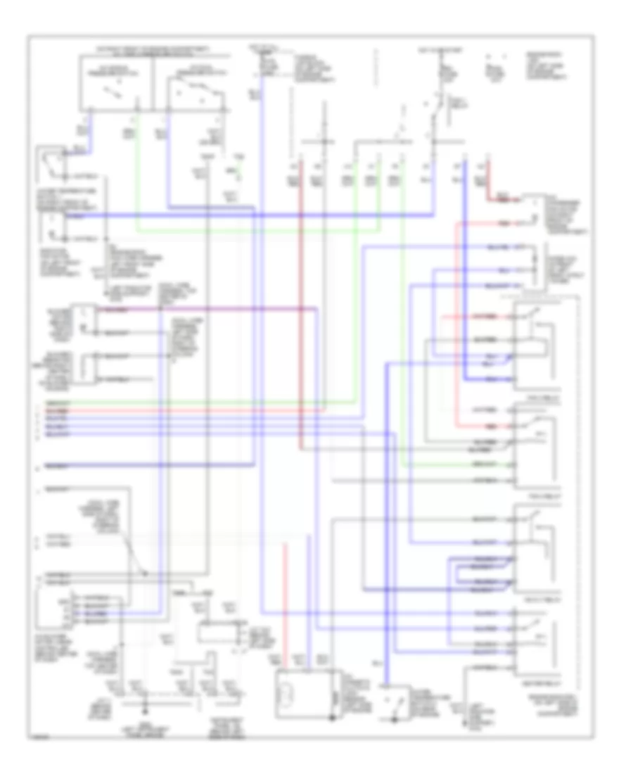
2.2L, Manual A/C Wiring Diagram (2 of 2) for Toyota Camry CE 2000
List of elements for 2.2L, Manual A/C Wiring Diagram (2 of 2) for Toyota Camry CE 2000:
- 2.2l
- 2.2l cng
- 2.2l w/ engine immobilizer
- 2.2l w/o engine immobilizer
- A/c condenser fan motor (right front of engine compt)
- A/c evaporator temperature sensor (on evaporator)
- A/c magnetic clutch & lock sensor (left side of engine)
- A/c pressure switch (right front of engine compt)
- A/cs
- Acmg
- Cds fuse 30a
- Dual pressure
- E10
- E11
- E4 (engine harn, e2: right front corner of engine compt, e4: left side of engine compt)
- Ecu-ig fuse 15a
- Engine control module (behind right side of dash)
- Engine room j/b 2 (left side of engine compt)
- Engine room r/b 1 (left side of engine compt)
- Fan 1 relay
- Fan 2 relay
- Fan 3 relay
- Fusible link block (left side of engine compt)
- G108 (left radiator side support)
- G131 (on intake manifold)
- Heater fuse 10a
- Hot at all times
- Hot in on
- Hot in on or start
- Htr fusible link 50a
- Htr relay
- Instrument panel j/b (behind dash, left of steering column)
- J/c 23 j/c 20 (behind right side of dash)
- J/c 32 j/c 30 (behind upper right end of dash)
- J/c 8 j/c 7 (behind left side of dash)
- Lcki
- Lock
- Mg clt relay
- Or start
- Prs
- Radiator fan motor (left front of engine compt)
- Rdi fuse 30a
- Red
- Single pressure
- Thr
- Water temperature switch 1 (right front of engine compt)
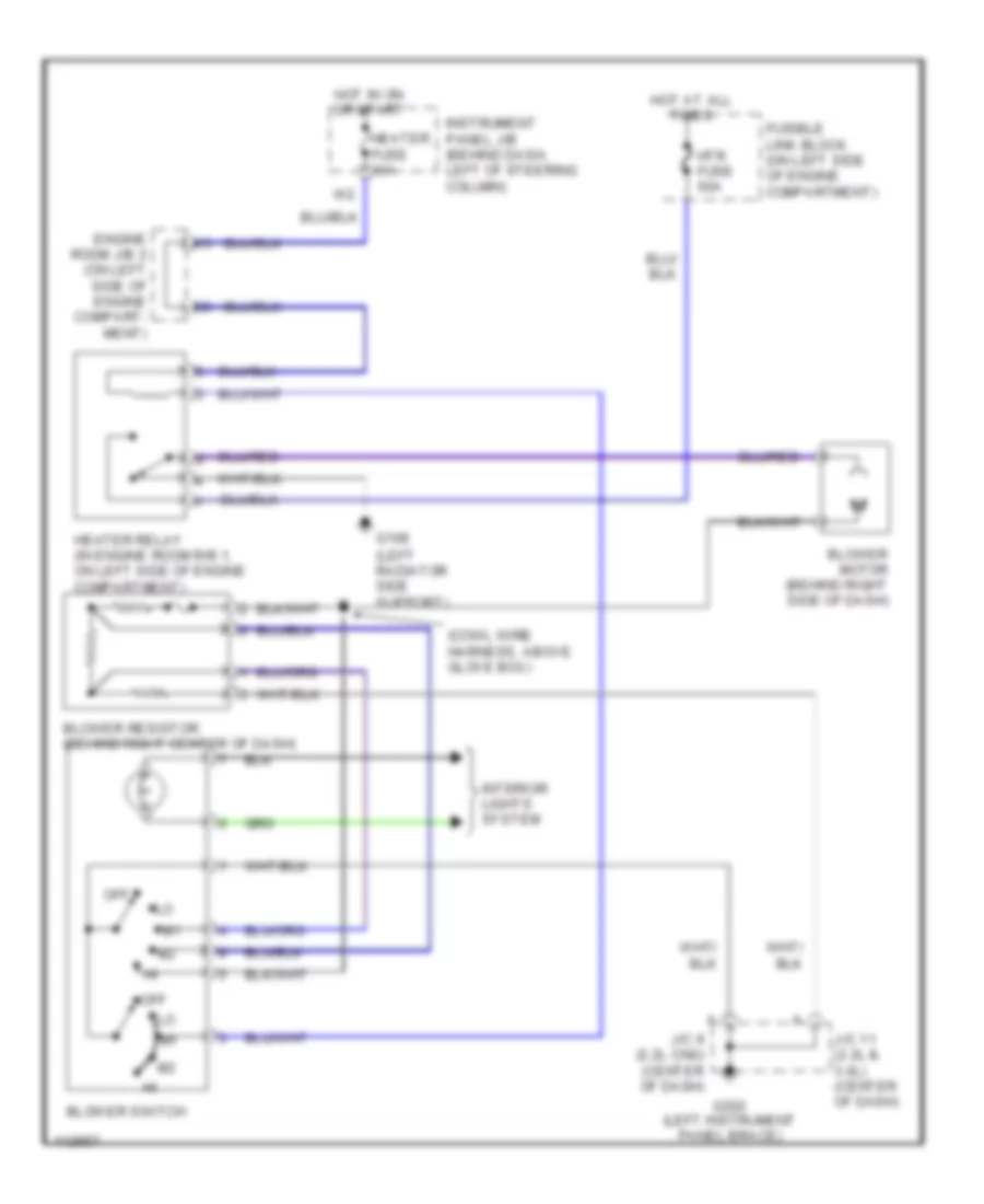
Heater Wiring Diagram for Toyota Camry CE 2000
List of elements for Heater Wiring Diagram for Toyota Camry CE 2000:
- (cowl wire harness, above glove box)
- (left radiator side support)
- Blower motor (behind right side of dash)
- Blower resistor (behind right center of dash)
- Blower switch
- Engine room j/b 2 (on left side of engine compart- ment)
- Fusible link block (on left side of engine compartment)
- G108
- G202 (left instrument panel brace)
- Heater fuse 10a
- Heater relay (in engine room r/b 1, on left side of engine compartment)
- Hot at all times
- Hot in on or start
- Htr fuse 50a
- Instrument panel j/b (behind dash, left of steering column)
- Interior lights system
- J/c 11 (2.2l & 3.0l) (center of dash)
- J/c 9 (2.2l cng) (center of dash)
- Off
3.0L
3.0L, Automatic A/C Wiring Diagram (1 of 2) for Toyota Camry CE 2000
List of elements for 3.0L, Automatic A/C Wiring Diagram (1 of 2) for Toyota Camry CE 2000:
- (cowl wire harness, behind center of dash)
- A/c
- A/c ambient temperature sensor (on front center of engine compartment)
- A/c control assembly (behind center of dash)
- A/c evaporator temperature sensor (behind right side of dash, on evaporator)
- A/c room temperature sensor (behind left side of dash, right side of steering column)
- A/c solar sensor (top left side of dash)
- A10
- A11
- A12
- A13
- A14
- A15
- A16
- A17
- A18
- A19
- A20
- A21
- A22
- A23
- A24
- A25
- A26
- A34
- A35
- Ac1
- Act
- Aif
- Air
- Air inlet control servo motor (behind right side of dash)
- Air mix control servo motor (behind left center of dash)
- Air vent mode control servo motor (behind right center of dash, on blower housing)
- Amc
- Amh
- B/l
- B10
- B11
- B12
- B13
- B14
- B15
- B16
- Blw
- Control circuit
- Cool
- Def
- Defogger system
- E11
- E29
- Ecu-b fuse 10a
- Ecu-ig fuse 15a
- Engine control module (behind right side of dash)
- Engine room j/b 2 (on left side of engine compart- ment)
- Engine room j/b 2 (on left side of engine compartment)
- F/d
- Face
- Foot
- Gnd
- Heater fuse 10a
- Hot at all times
- Hot in on or start
- I10 (cowl wire harness, above glove box)
- I13
- Ig+
- Ign
- Illum
- Instrument cluster system
- Instrument panel j/b (behind dash, left of steering column)
- Interior lights system
- J/c 1 (behind left kick panel)
- J/c 27 & j/c 28 (behind right side of dash)
- J/c 29 (behind right side of dash)
- J/c 32 (behind right kick panel)
- J27
- J28
- Lock
- Mgcr
- Motor position switches
- Pnk
- Psw
- Rdfg
- Red
- Spd
- Tach
- Tam
- Thwo
- Tpi
- V10
- Warm
3.0L, Automatic A/C Wiring Diagram (2 of 2) for Toyota Camry CE 2000
List of elements for 3.0L, Automatic A/C Wiring Diagram (2 of 2) for Toyota Camry CE 2000:
- (cowl wire harness, left side of dash, right of steering column)
- (cowl wire harness, left side of dash, right of steering column) i8
- (cowl wire harness, top center of dash) i7
- (left radiator side support) g108
- (on right front of engine compartment) a/c triple pressure switch
- A/c blower motor linear controller (behind center of dash)
- A/c condenser fan motor (on right front of engine compartment)
- A/c dual pressure switch
- A/c magnetic clutch & lock sensor (left side of engine)
- A/c single pressure switch
- Blower motor (behind right side of dash)
- Blower resistor (behind right center of dash, on blower housing)
- Cds fuse 30a
- Compartment)
- Diode (a/c) (in front of left front strut tower)
- Engine room j/b 2 (on left side of engine compartment)
- Engine room r/b 1 (on left side of engine compartment)
- Fan 1 relay
- Fan 2 relay
- Fan 3 relay
- Fusible link block (on left side of engine compartment)
- G202 (left instrument panel brace)
- Gnd
- Heater relay
- Hot at all times
- Hot in or start
- Htr fuse 50a
- I7 (cowl wire harness, top center of dash)
- Instrument panel j/b (behind left side of dash)
- J/c 11 (behind center of dash)
- J/c 7 & 8 (behind left side of dash)
- J13
- J7 a
- J8 a
- Mg clt relay
- Radiator fan motor (on left front of engine compartment)
- Rdi fuse 30a
- Red
- Tmc
- Tmmk
- Water temperature switch 1 (on right front of engine compartment)
- Water temperature switch 2 (on rear of engine)
3.0L, Manual A/C Wiring Diagram (1 of 2) for Toyota Camry CE 2000
List of elements for 3.0L, Manual A/C Wiring Diagram (1 of 2) for Toyota Camry CE 2000:
- (cowl wire harn, above glove box) i3
- (cowl wire harn, behind center of dash)
- (cowl wire harn, right side of dash)
- A/c
- A/c amplifier (behind glove box)
- A/c evaporator temperature sensor (on evaporator)
- A/c fuse 10a
- Ac1
- Act
- Air inlet control servo motor
- Air inlet controls
- Air vent mode control servo motor (behind right center of dash, on blower motor)
- B/l
- Blower resistor (behind right center of dash)
- Blower motor (behind right side of dash)
- Blower switch
- Control circuit
- Controls air vent
- Def
- E11 e29
- Ecu-b fuse 10a
- Engine control module (behind right side of dash)
- Engine room j/b 2 (left side of engine compt)
- Engine room r/b 1 (left side of engine compt)
- F j27
- F/d
- Face
- Foot
- Fresh
- G202 (left instrument panel brace)
- Gnd
- H15
- Heater control switch
- Hot in on
- I14
- I9 (cowl wire harn, behind center of dash)
- Ign
- Instrument panel j/b (behind dash, left of steering column)
- Interior lights system
- J/c 11 (behind center of dash)
- J/c 12 (below top center of dash)
- J/c 27 & j/c 28 (behind right side of dash)
- J/c 29 (behind right side of dash)
- J28 d
- L-a/c
- Lock
- Mgc
- Motor position switches
- Off
- Or start
- Recirc
- Red
- S-a/c
- Tach
- Tmc
- Tmmk
- V10
3.0L, Manual A/C Wiring Diagram (2 of 2) for Toyota Camry CE 2000
List of elements for 3.0L, Manual A/C Wiring Diagram (2 of 2) for Toyota Camry CE 2000:
- A/c condenser fan motor (right front of engine compt)
- A/c magnetic clutch & lock sensor (left side of engine)
- A/c pressure switch (right front of engine compt)
- A/c switch
- Cds fuse 30a
- Diode (a/c) (in front of left front strut tower)
- Dual pressure
- Ecu-ig fuse 15a
- Engine room j/b 2 (left side of engine compt)
- Engine room r/b 1 (left side of engine compt)
- Fan 1 relay
- Fan 2 relay
- Fan 3 relay
- Fusible link block (left side of engine compt)
- G108 (left radiator side support)
- Heater fuse 10a
- Hot at all times
- Hot in on
- Hot in on or start
- Htr fusible link 50a
- Htr relay
- Instrument panel j/b (behind dash, left of steering column)
- Interior lights system
- J/c 12 (below top center of dash)
- J/c 32 (behind right kick panel)
- J13
- Mg clt relay
- Or start
- Radiator fan motor (left front of engine compt)
- Rdi fuse 30a
- Red
- Single pressure
- Water temperature switch 1 (right front of engine compt)
- Water temperature switch 2 (on rear of engine)
Heater Wiring Diagram for Toyota Camry CE 2000
List of elements for Heater Wiring Diagram for Toyota Camry CE 2000:
- (cowl wire harness, above glove box)
- (left radiator side support)
- Blower motor (behind right side of dash)
- Blower resistor (behind right center of dash)
- Blower switch
- Engine room j/b 2 (on left side of engine compart- ment)
- Fusible link block (on left side of engine compartment)
- G108
- G202 (left instrument panel brace)
- Heater fuse 10a
- Heater relay (in engine room r/b 1, on left side of engine compartment)
- Hot at all times
- Hot in on or start
- Htr fuse 50a
- Instrument panel j/b (behind dash, left of steering column)
- Interior lights system
- J/c 11 (2.2l & 3.0l) (center of dash)
- J/c 9 (2.2l cng) (center of dash)
- Off

 Čeština
 Dansk
Dansk Deutsch
 Ελληνικά
 English
 English
 Español
 Suomi
Suomi Français
 Français
 עברית
עברית Hrvatski
 Magyar
 Italiano
 日本語
日本語 한국어
한국어 Nederlands
 Português
 Português
 Română
 Русский
 Slovenčina
 Slovenščina
 Svenska
 Türkçe
 中文 (中国)