AIR CONDITIONING
Air Conditioning Wiring Diagrams for Chevrolet Beretta Z26 1995
 https://portal-diagnostov.com/license.html
Automotive Electricians Portal FZCO
Automotive Electricians Portal FZCO
https://portal-diagnostov.com/license.html
https://portal-diagnostov.com/license.html
Automotive Electricians Portal FZCO
Automotive Electricians Portal FZCO
List of elements for Air Conditioning Wiring Diagrams for Chevrolet Beretta Z26 1995:
- (l4 vin 4)
- (v6 vin m)
- +5v
- A/c clutch diode
- A/c compressor clutch
- A/c compressor control relay (right front of engine compartment on relay bracket)
- A/c request
- A/c sensor (right front of engine compartment) (left front of engine)
- Bi-lv
- Blend
- Blower motor
- Blower motor relay (right rear of engine compartment)
- Blower resistors (rear of engine compartment)
- Blower switch
- C tan
- C10
- C11
- Coolant fan
- D12
- Def
- Engine coolant temperature sensor (rear of engine)
- Fan control relay (lower left rear of engine)
- Fuse 20a
- Fuse 25a
- Fuse block
- G129 (on transaxle stud)
- Heater-a/c control assembly
- Hot at all times
- Hot in run
- Hot in run, bulb test or start
- Htr
- L4 vin 4
- Max
- Mode switch
- Norm
- Off
- Pnk
- Powertrain control module (behind right side of i/p)
- Red
- Relay control
- Sensor ground
- Sensor input
- Solid state
- Tan
- Temperature selector
- Temperature valve motor (left side of steering column brace)
- V6 vin m
- Vent
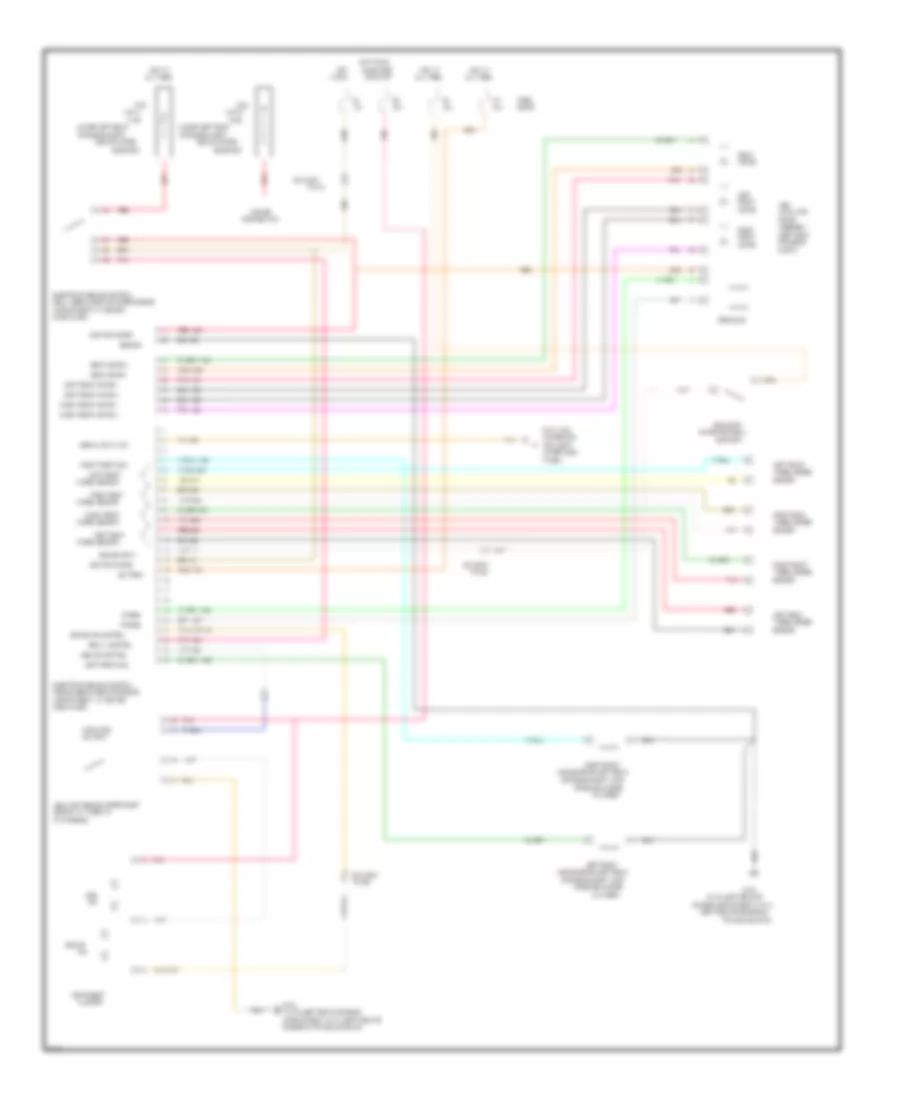
ANTI-LOCK BRAKES
Anti-lock Brake Wiring Diagrams for Chevrolet Beretta Z26 1995
List of elements for Anti-lock Brake Wiring Diagrams for Chevrolet Beretta Z26 1995:
- #11
- (dlc) (left
- (left rear
- (left rear of engine on
- (lower left rear
- (on brake pedal
- (vin m) (left rear of
- (vin m) (left rear of engine
- 10a
- 14 ga
- 16 ga
- 20a
- Abs
- Abs ind control
- Abs lamp module (upper right
- Abs solenoid (left rear
- Actuator
- All times
- Assembly
- B/h conn
- Battery
- Block
- Brake
- Brake ind control
- Brake input
- Brake sw
- Bulb test
- Cluster
- Compartment at center
- Compartment) (vin 4) (left rear of
- Compartment, at center
- Compt)
- Connector
- Cylinder)
- Dash panel)
- Data link
- Distribution
- Electronic brake control
- Emb coils
- Engine compartment) (vin 4)
- Engine on transaxle stud)
- Front
- Fus
- Fuse
- G130
- Ground
- Hot
- Hot at
- Hot in run,
- I/p harness)
- Ignition power
- In run
- Ind
- Indicator
- Instrument
- Left
- Left front
- Left front
- Left front motor +
- Left front motor /
- Left front sol
- Left rear
- Lf emb
- Link a
- Link d
- Lower hush
- Module (ebcm) (rear of engine
- Motor
- Near starter
- Of brake master
- Of engine
- Of engine compt,
- Of engine compt, part
- On input
- Or start
- Panel)
- Pin b5
- Pin c4
- Pin c6
- Pnk
- Pnk 1281
- Pnk 1632
- Power
- Rear
- Rear motor +
- Rear motor /
- Red
- Red 1633
- Red 885
- Relay (ebcm) (rear of upper engine
- Relay control
- Rf emb
- Right
- Right front
- Right front
- Right front motor +
- Right front motor /
- Right front sol
- Right rear
- Sensor
- Serial data link
- Side of i/p, taped to
- Solenoid)
- Support)
- Tan
- Tan 800
- Tan 883
- Transaxle stud)
- Wheel sensor
- Wheel speed
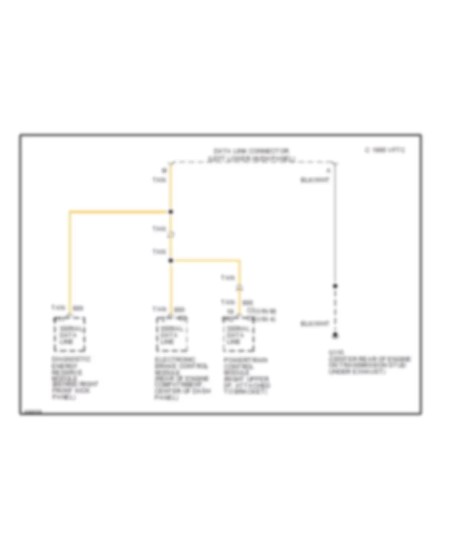
COMPUTER DATA LINES
Data Link Connector Wiring Diagram for Chevrolet Beretta Z26 1995
List of elements for Data Link Connector Wiring Diagram for Chevrolet Beretta Z26 1995:
- (vin m) (vin 4)
- 1995 vftc c
- A11
- C2 c3
- D12
- Data link connector (left lower hush panel)
- Diagnostic energy reserve module (behind right front kick panel)
- Electronic brake control module (rear of engine compatrment, center of dash panel)
- G115 (center rear of engine on transmission stud under exhaust)
- Powertrain control module (right upper i/p, attached to bracket)
- Serial data line
- Tan
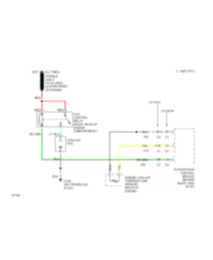
COOLING FAN
Cooling Fan Wiring Diagram for Chevrolet Beretta Z26 1995
List of elements for Cooling Fan Wiring Diagram for Chevrolet Beretta Z26 1995:
- C 1995 vftc
- C10
- Coolant fan
- Engine coolant temperature sensor (rear of engine)
- Fan control relay (right rear of engine compartment)
- G129 (on transaxle stud)
- Hot at all times
- L4 vin 4
- Powertrain control module (behind right side of i/p)
- Red
- V6 vin m
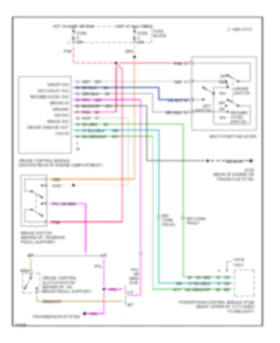
CRUISE CONTROL
Cruise Control Wiring Diagram for Chevrolet Beretta Z26 1995
List of elements for Cruise Control Wiring Diagram for Chevrolet Beretta Z26 1995:
- 1995 vftc c
- A/t
- B/h conn pin e6
- B/h conn pin e7
- Brake in
- Brake sig
- Brake switch (behind i/p, on brake pedal support)
- Cruise control clutch switch (behind i/p, on brake pedal support)
- Cruise control module (center rear of engine compartment)
- Cruise engage out
- Cruise switch
- Fuse 20a
- Fuse block
- G129 (rear of engine on transaxle stud)
- Ground
- Hot at all times
- Hot in accy or run
- Ign sig
- M/t
- Multi-function lever
- Off
- On/off sig
- Pnk
- Powertrain control module (pcm) (right upper i/p, attached to bracket)
- R/a
- Resume/ accel r/a
- Resume/accel sig
- Set switch
- Set/coast sig
- Switch
- Transmission system
- Vin 4
- Vin m
- Vss in
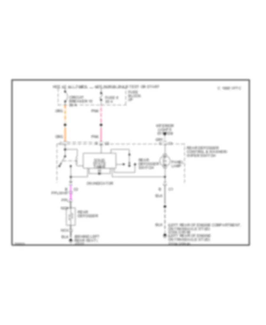
DEFOGGERS
Defogger Wiring Diagram for Chevrolet Beretta Z26 1995
List of elements for Defogger Wiring Diagram for Chevrolet Beretta Z26 1995:
- (behind left rear seat) g312
- (left rear of engine compartment, on transaxle stud) g104 (left rear of engine on transaxle stud) g114
- (vin 4)
- (vin m)
- 1995 vftc c
- Circuit breaker 15 30 a
- Fuse 9 20 a
- Fuse block: i/p
- Hot at all times
- Hot in run, bulb test or start
- Interior lights system
- Nca
- On indicator
- Panel lamp
- Pnk
- Rear defogger
- Rear defogger control & washer/ wiper switch
- Rear defogger switch
- Solid state timer
ENGINE PERFORMANCE
2.2L
2.2L (VIN 4), Engine Performance Wiring Diagrams (1 of 2) for Chevrolet Beretta Z26 1995
List of elements for 2.2L (VIN 4), Engine Performance Wiring Diagrams (1 of 2) for Chevrolet Beretta Z26 1995:
- 5 volts ref
- A/c press signal
- A/c request
- A/c sensor (right front of engine compt)
- A10
- A11
- A12
- B10
- B11
- B12
- Battery ref
- C10
- C11
- C12
- C13
- C14
- C15
- C16
- Conn c1
- Conn c2
- Crank sens output
- Crank sensor b+ feed
- Crank sensor grd
- Crank shaft position sensor (lower right side of engine)
- D10
- D11
- D12
- D13
- D14
- D15
- D16
- Ect sensor in
- Engine control module (ecm) (behind right side of i/p, near shroud)
- Engine coolant temperature sensor (left side of engine)
- Fuel injector #1
- Fuel injector #2
- Fuel injector #3
- Fuel injector #4
- Fuel pump relay ctrl
- Fuse 20a
- Fuse block
- Fusible link (20 ga-gray)
- G117 right rear of engine, on transaxle stud)
- Ground
- Heater and a/c ctrl assembly
- Hot at all times
- Hot in run, bulb test or start
- Iac a hi
- Iac a lo
- Iac b hi
- Iac b lo
- Iat sensor in
- Idle air control valve (top left rear of engine, on right front of throttle body)
- Ign ctrl a out
- Ign ctrl b out
- Injector 1 & 4 ctrl
- Injector 2 & 3 ctrl
- Instrument cluster
- Instrument cluster, cruise control and convenience center
- Intake air temp (iat) sensor (left front of engine comp, on right side of air cleaner)
- Map sensor (top left rear of engine, near throttle body)
- Map signal in
- Oil level signal
- Oxygen sensor (rear of engine on exhaust manifold)
- Oxygen sensor in-hi
- Oxygen sensor in-lo
- Pnk
- Red
- Sensor ground
- Tach
- Tan
- Throttle position (tp) sensor (top rear of engine, on left side of throttle body)
- Tps
- Vss out
2.2L (VIN 4), Engine Performance Wiring Diagrams (2 of 2) for Chevrolet Beretta Z26 1995
List of elements for 2.2L (VIN 4), Engine Performance Wiring Diagrams (2 of 2) for Chevrolet Beretta Z26 1995:
- (right rear of engine,
- (under left side of driver's seat)
- 3rd gear sw
- 456/422
- 87a
- A/c control relay
- A/c relay ctrl
- A/t
- Brake switch (behind dash, on brake pedal support)
- C10
- C11
- C12
- C13
- C14
- C15
- C16
- Canister purge sol valve (right front of engine compt)
- Conn c3
- Convenience center
- Coolant fan relay
- Coolant fan relay ctrl
- Coolant ind ctrl
- Coolant indicator
- D10
- D11
- D12
- D13
- D14
- D15
- D16
- Data link connector
- Dlc serial data in/out
- Egr solenoid ctrl
- Egr valve (left rear of engine, near map sensor)
- Electronic ignition (ei) system (rear of engine, above transaxle)
- Engine control module (ecm) (behind right side of i/p, near shroud)
- Evao ctrl
- Fuel pump prime conn
- Fuel pump relay (right rear of engine compt, behind strut tower)
- Fuel pump sw/ oil pres sender/sw (right rear of engine, near elect ignition (ei) system)
- Fuel tank/ pump unit
- Fuse 15a
- Fuse 20a
- Fuse block
- G117
- G117 (right rear of engine, on trans stud)
- G300
- Hot in run, bulb test or start
- Ignition
- Ignition coil
- Instrument cluster
- Knock sensor (rear of engine, below right side of exhaust manifold)
- Knock sensor in
- Low oil level ind ctrl
- Low oil level indicator
- M/t
- Malfunction ind ctrl
- Malfunction indicator
- Nca
- On transaxle stud)
- Park/neutral in
- Park/neutral position switch (a/t) (lower right rear of engine, top of transaxle)
- Pnk
- Pri
- Red
- Sec
- Shift indicator
- Spark plugs
- Sw a
- Sw b
- Tan
- Tcc solenoid
- Upshift ind/tcc ctrl
- Vehicle speed sensor (rear of engine)
- Vss in hi
- Vss in lo
- Z pnk
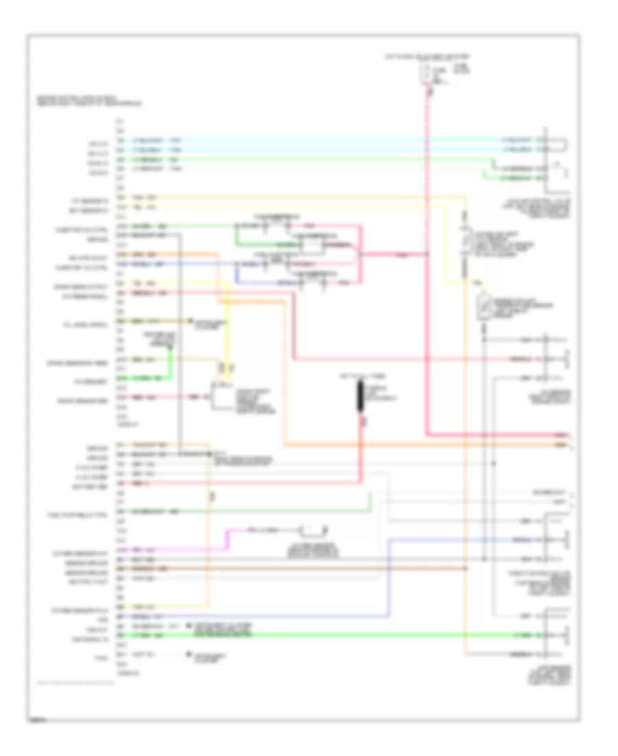
3.1L
3.1L (VIN M), Engine Performance Wiring Diagrams (1 of 2) for Chevrolet Beretta Z26 1995
List of elements for 3.1L (VIN M), Engine Performance Wiring Diagrams (1 of 2) for Chevrolet Beretta Z26 1995:
- (22 ga-rust)
- (left rear of engine rear of throttle body)
- (on right side transaxle output housing)
- (right front of engine compartment)
- (right rear top of engine)
- (top rear of engine, in throttle body air tube)
- (top right rear of eng, near exhaust system)
- (top right side of
- 5 volt ref
- A/c clutch relay
- A/c press sens signal
- A/c relay ctrl
- A/c request
- A/c sensor
- Battery
- Brake sw input
- Check gauges lamp
- Conn c1
- Conn c2
- Convenience center
- Convenience center, speedo,
- Coolant temp sensor
- Cooling fan relay ctrl
- Cruise control, wiper/washer
- Data link connector (lower left hush panel)
- Digital exhaust gas recirculation assembly
- Ect signal
- Egr sol "a" ctrl
- Egr sol "b" ctrl
- Egr sol "c" ctrl
- Engine, on rocker cover)
- Evap driver
- Evaporative emission canister purge valve
- Fan control relay
- Fuel pump relay ctrl
- Fuel pump relay monitor
- Fuse 10a
- Fuse 20a
- Fuse block
- Fusible link e
- G115 (center rear of engine on transaxle stud)
- G116 (left rear of engine compartment, on dash panel)
- Ground
- Heated oxygen sensor (upper right side of engine on exhaust manifold)
- Heater & a/c control assembly
- Hot at all times
- Hot in run
- Hot in run, bulb
- Idle air ctrl valve "a" (hi)
- Idle air ctrl valve "a" (lo)
- Idle air ctrl valve "b" (hi)
- Idle air ctrl valve "b" (lo)
- Idle air ctrl valve (top rear of engine, on throttle body)
- Instrument cluster
- Intake air temp sensor
- Low oil ind ctrl
- Malfunction ind control
- Malfunction indicator
- Manifold absolute pressure sensor
- Map signal
- Oil level signal
- Oxygen sensor ground
- Oxygen sensor signal
- Park/neutral out
- Pnk
- Pnp switch in
- Powertrain control module (upper right of i/p, attached to bracket)
- Red
- Sensor ground
- Serial data in/out
- Shift sol "a" ctrl
- Shift sol "b" ctrl
- Sol a
- Sol b
- Sol c
- Tan
- Tcc sol ctrl
- Test or start
- Throttle position sensor (rear of engine, right side of throttle body)
- Tps signal
- Trans fluid temp sensor
- Trans pos input "a"
- Trans pos input "b"
- Trans pos input "c"
- Vehicle speed sensor
- Vehicle speed sensor (hi)
- Vehicle speed sensor (lo)
- Vehicle speed signal
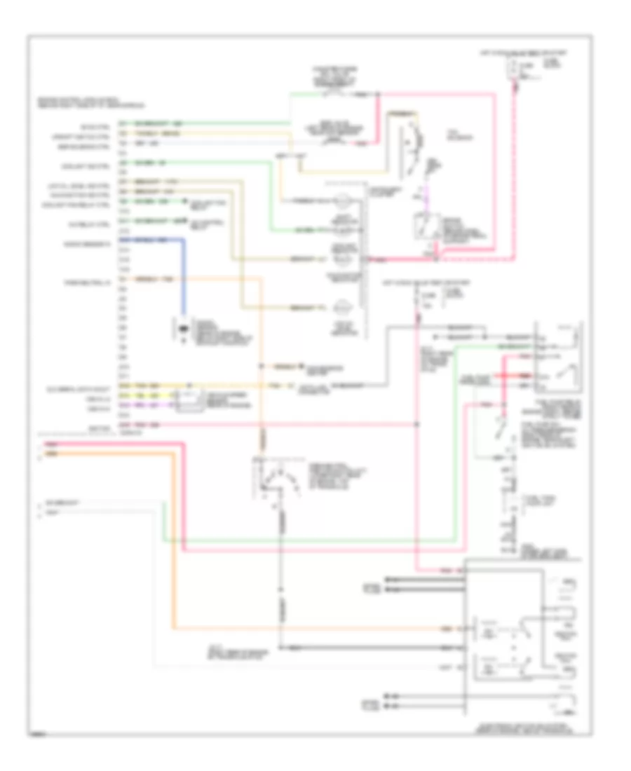
3.1L (VIN M), Engine Performance Wiring Diagrams (2 of 2) for Chevrolet Beretta Z26 1995
List of elements for 3.1L (VIN M), Engine Performance Wiring Diagrams (2 of 2) for Chevrolet Beretta Z26 1995:
- (right top of engine
- 87a
- Automatic transaxle
- Brake switch (on brake pedal support)
- Cam position sensor in
- Camshaft position sensor (upper right front of engine)
- Compartment, behind generator)
- Conn c3
- Crank pos sensor in
- Crank position sensor (lower right side of engine)
- Crank/cam pos sensor rtn
- Cruise control module
- Cruise on in
- E pnk
- Electronic ignition system
- Est bypass sig
- Est ctrl sig
- Fuel inj 1 out
- Fuel inj 2 out
- Fuel inj 3 out
- Fuel inj 4 out
- Fuel inj 5 out
- Fuel inj 6 out
- Fuel pump switch/oil pressure sensor sw (right front of engine block)
- Fuel pump priming conn
- Fuel pump relay (right rear of engine compt, behind strut tower)
- Fuel tank unit (top of fuel tank)
- Fuse 15a
- Fuse 20a
- Fuse block
- G115 (center rear of engine, on transaxle stud)
- G300 (under left front seat, near door sill)
- Ground
- Hot in run, bulb test, or start
- Ignition
- Ignition amplifier and switching module
- Inj
- Interlock
- Knock sensor (right front of engine block)
- Knock sensor in
- Mat sensor in
- Nca
- Park/neutral position switch (left rear of engine, right top of transaxle)
- Plugs spark
- Pnk
- Powertrain control module (upper right of i/p, attached to bracket)
- Red
- Ref pulse hi in
- Ref pulse low in
- Shift
- Shift sol a
- Shift sol b
- Spark plugs
- Tachometer
- Tan
- Tcc pwm sol
- Trans temp sensor
- Transaxle converter clutch
EXTERIOR LIGHTS
Exterior Light Wiring Diagram (1 of 2) for Chevrolet Beretta Z26 1995
List of elements for Exterior Light Wiring Diagram (1 of 2) for Chevrolet Beretta Z26 1995:
- 1995 vftc c
- Anti-lock brakes system
- B/h conn pin b1
- B/h conn pin c7
- B/h conn pin f2
- B/h conn pin g2
- B/h conn pin m
- B/h conn pin r
- Back-up lights switch (top of transaxle)
- Brake switch (on brake pedal support)
- Center high mounted stop light assembly
- Convenience center (left side of i/p)
- Coupe
- Coupe w/ spoiler
- Coupe/sedan
- Engine controls system
- Ex vin 4 m/t
- Fuse 2 20a
- Fuse 5 20a
- Fuse 7 20a
- Fuse block
- G129 (on transaxle stud)
- G300 (under left side of driver seat, near door sill)
- G400 (left rear of trunk, near shock tower)
- Hazard
- Hazard flasher
- Head
- Hot at all times
- Hot in run, bulb test or start
- Instrument cluster
- Left back-up light
- Left back-up lights
- Left turn ind
- Left turn sw
- Light switch
- Normal
- Off
- Park
- Park/neutral position switch (right top of transaxle)
- Pnk
- Right back-up light
- Right back-up lights
- Right turn ind
- Right turn sw
- Sedan
- To front lights
- To front park lights
- To rear lights
- To stop/turn lights
- Turn flasher (right of steering column)
- Turn/ hazard switch
- Vin 4 m/t
- Vin m only
- Warning system
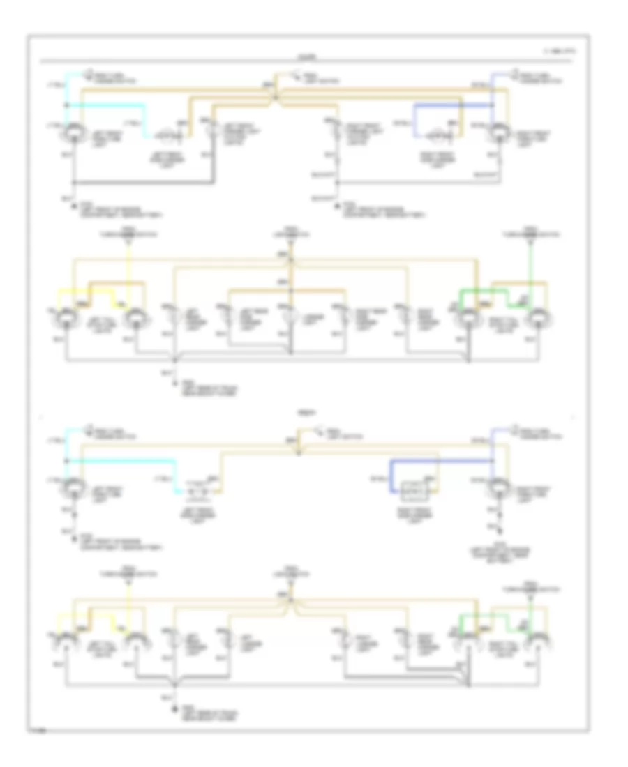
Exterior Light Wiring Diagram (2 of 2) for Chevrolet Beretta Z26 1995
List of elements for Exterior Light Wiring Diagram (2 of 2) for Chevrolet Beretta Z26 1995:
- 1995 vftc c
- Coupe
- From light switch
- From turn/ hazard switch
- From turn/hazard switch
- G100 (left front of engine compartment, near battery)
- G400 (left rear of trunk, near shock tower)
- Left front marker light (w/o fog lights)
- Left front park/turn light
- Left front side marker light
- Left license light
- Left rear marker light
- Left rear side marker light
- Left tail/ stop/turn lights
- License light
- Right front marker light (w/o fog lights)
- Right front park/turn light
- Right front side marker light
- Right license light
- Right rear marker light
- Right rear side marker light
- Right tail/ stop/turn lights
- Sedan
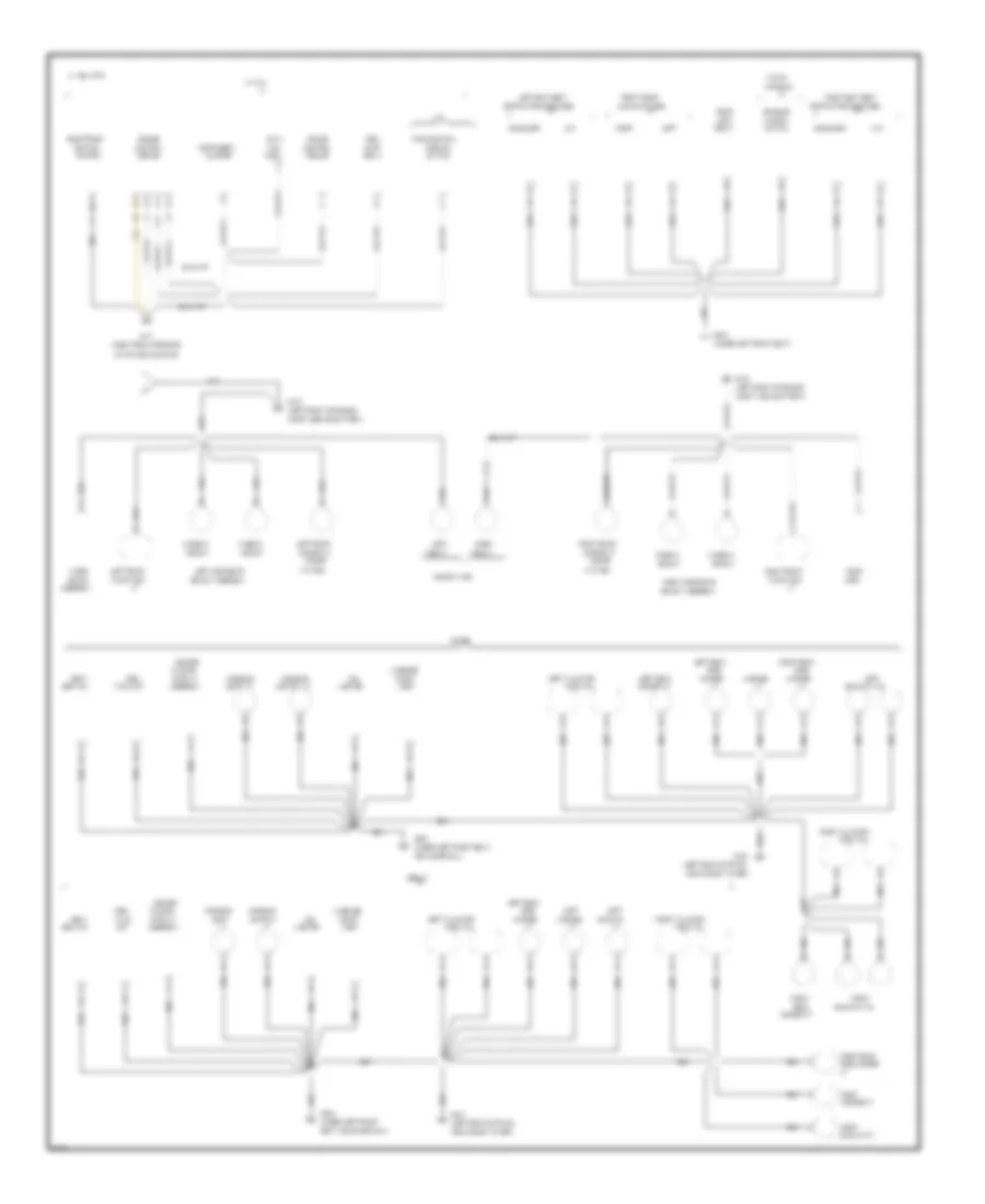
GROUND DISTRIBUTION
Ground Distribution Wiring Diagram (1 of 2) for Chevrolet Beretta Z26 1995
List of elements for Ground Distribution Wiring Diagram (1 of 2) for Chevrolet Beretta Z26 1995:
- (a/t)
- (center rear of engine, on transaxle stud near exhaust pipe)
- (left rear of engine compartment,
- (left rear of engine, above starter)
- (w/o daytime
- 1994 vftc c
- A/c
- A/c control
- A12
- Abs
- Alarm
- Assembly
- B/h conn
- Battery
- Blower
- Brake
- Brake fluid
- Cluster
- Clutch
- Compartment
- Compressor
- Conn
- Control
- Control &
- Coolant
- Cruise
- Data
- Daytime
- Defogger
- Diagnostic
- Diode
- Discriminating
- Door
- Electronic
- Energy
- Engine
- Fan
- Forward
- Fuel
- Function
- G114
- G115
- G116
- Headlight
- Heated
- Heater/
- Ignition
- Instrument
- Interlock
- Lamp
- Left front
- Left hi beam
- Level
- Light sw
- Lights
- Link
- Low
- Module
- Motor
- Multi/
- Nca
- Oil
- On dash panel)
- Oxygen
- Passenger
- Pin b7
- Pump
- Radio
- Rear
- Relay
- Reserve
- Right front
- Running
- Running lights)
- Sensor
- Shift
- Solenoid
- Switch
- System
- Temp
- Transaxle
- Unlock
- V6 vin m
- V6 vin m only
- Valve
- Washer sw
- Wiper/
Ground Distribution Wiring Diagram (2 of 2) for Chevrolet Beretta Z26 1995
List of elements for Ground Distribution Wiring Diagram (2 of 2) for Chevrolet Beretta Z26 1995:
- (coupe
- (left front of engine
- (left rear of trunk,
- (right rear of engine,
- (under left front
- (under left front seat)
- (under left front seat,
- 1994 vftc c
- A/t
- Ashtray
- Ashtray lt
- Assembly
- Back/up
- Back/up lt
- Back/up lts
- Belt sw
- C13
- Center
- Cig
- Cluster
- Compt
- Compt, behind battery)
- Compt, near battery)
- Conn
- Console
- Control
- Coupe
- Coupe w/t96
- Cruise
- Data
- Door
- Electronic
- Engine
- Fog lt
- Front door
- Fuel
- G100
- G117
- G300
- G404
- Headlt
- Headlt assembly
- Hi beam
- Hi level
- Horn
- Ignition
- Instrument
- L4 vin 4
- Lap
- Left
- Left composite
- Left front
- Left rear
- Left seat belt
- Left tail/stop/
- License
- License lt
- Light
- Lighter
- Link
- Lo beam
- Lock
- Lock switches
- Luggage
- Marker
- Marker lt
- Module
- Motor
- Near door sill)
- Near shock tower)
- On transaxle stud)
- Park/neutral
- Park/turn
- Postion
- Pump
- Rear
- Relay
- Retractor solenoids
- Right
- Right composite
- Right front
- Right rear
- Right seat belt
- Right tail/stop/
- Seat
- Seat, near door sill)
- Sedan
- Shift
- Shift lt
- Shoulder
- Side
- Side marker
- Stop lt
- Switch
- System
- Tan
- Tank
- Tank unit
- Turn lts
- Unit
- W/o t96)
- W/pwr
- Window
- Windows
- Wiper
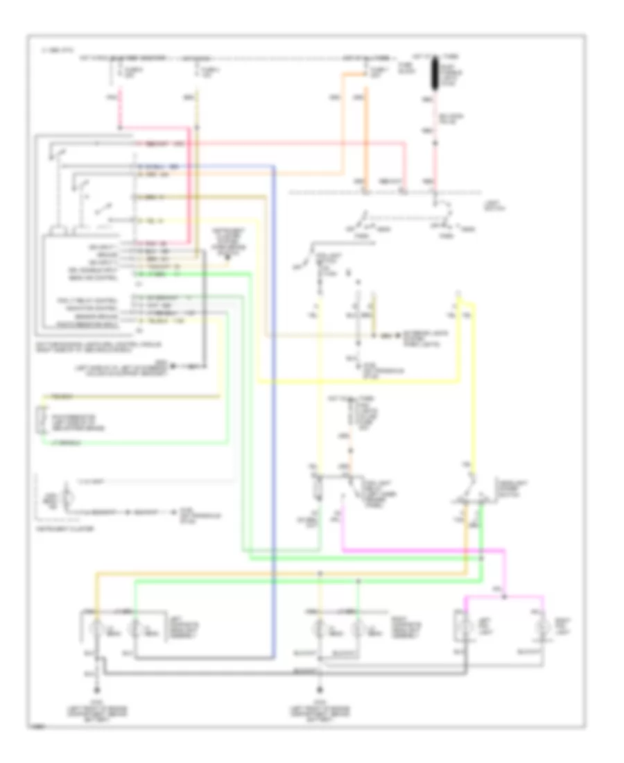
HEADLIGHTS
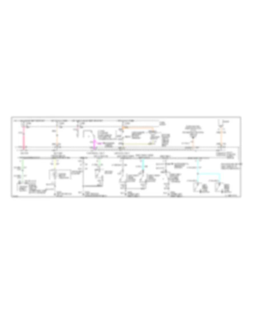
Headlight Wiring Diagram, with DRL for Chevrolet Beretta Z26 1995
List of elements for Headlight Wiring Diagram, with DRL for Chevrolet Beretta Z26 1995:
- 1995 vftc c
- B/h conn pin a5
- Beam ind control
- Daytime running lights (drl) control module (right side of i/p, above glove box)
- Drl disable input
- Exterior lights system (park lights)
- Fog light relay (left inner fender panel)
- Fog light switch
- Fog lights in-line fuse 20a
- Fog lt relay control
- Fuse 4 10a
- Fuse 7 20a
- Fuse 9 20a
- Fuse block
- G100 (left front of engine compartment, behind battery)
- G129 (on transaxle stud)
- G202 (left side of i/p, left of steering column on support bracket)
- Ground
- Head
- Headlight dimmer switch
- Hi beam
- High beam ind
- Hot at all times
- Hot in run
- Hot in run, bulb test or start
- Ign input 1
- Ign input 3
- Indicator control
- Instrument cluster
- Instrument cluster system (park brake switch)
- Left composite headlight assembly
- Left fog light
- Light switch
- Lo beam
- Off
- Park
- Photo resistor input
- Photoresistor (left side of i/p, above park brake)
- Pnk
- Red
- Right composite headlight assembly
- Right fog light
- Rust fusible link d 16 ga
- Sensor ground
- Tan
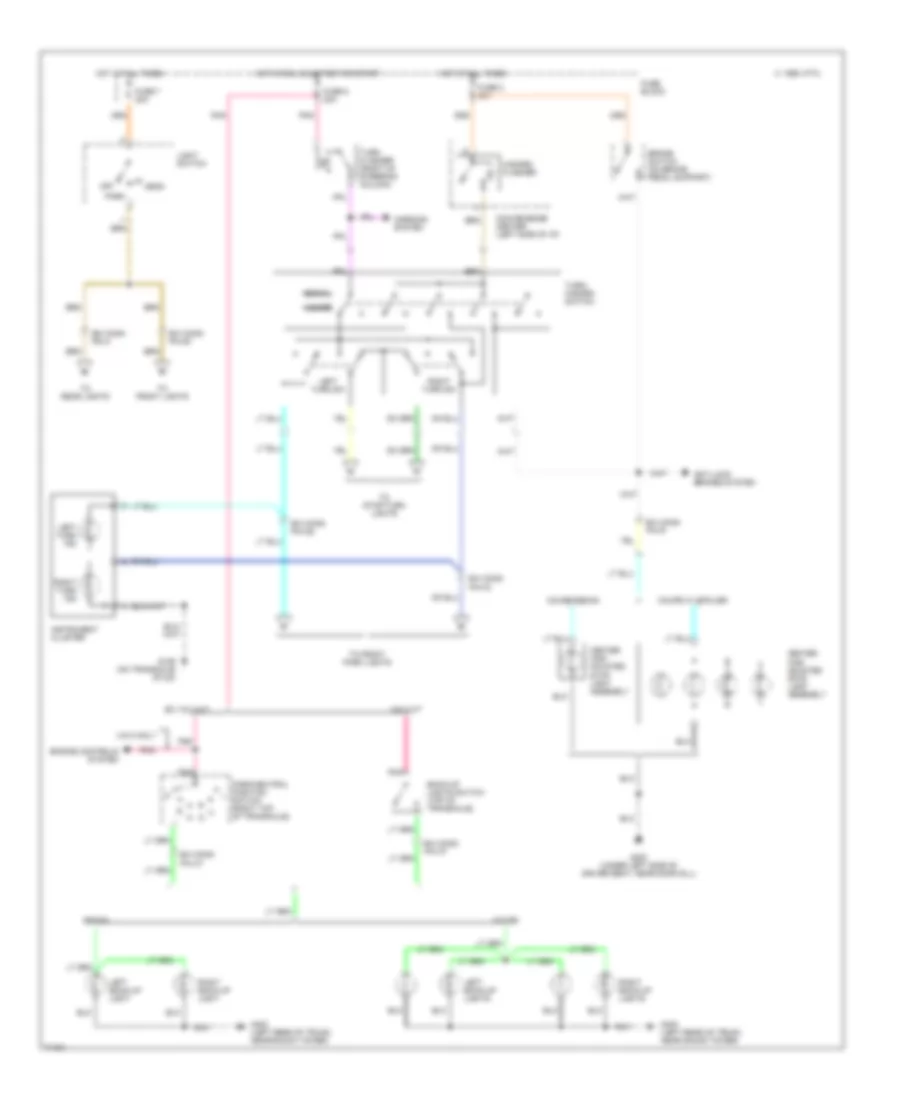
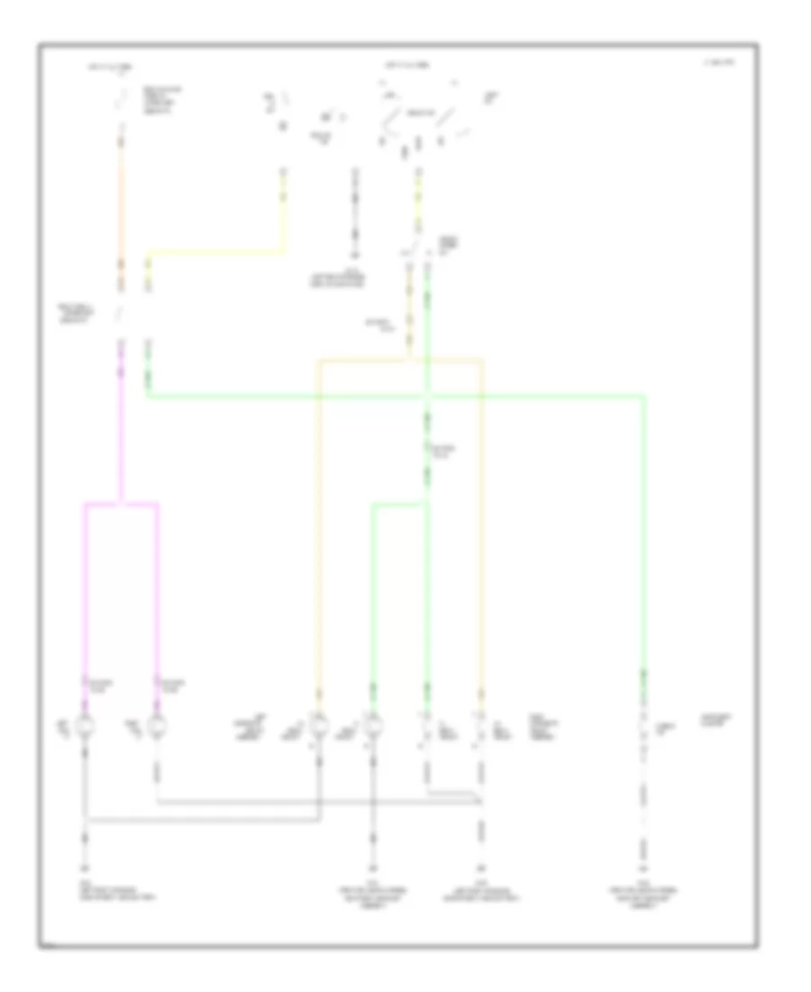
Headlight Wiring Diagram, with Fog Lamps for Chevrolet Beretta Z26 1995
List of elements for Headlight Wiring Diagram, with Fog Lamps for Chevrolet Beretta Z26 1995:
- (forward lights harness,
- (left front of engine
- (left rear of engine
- (upper left
- (upper left
- 1994 vftc c
- Assembly
- Assembly)
- B/h conn
- Beam
- Cluster
- Comp, on dash panel)
- Compartment, near battery)
- Composite
- Dimmer
- Fog
- Fog lt relay
- Fog lts
- Fog lts in/line
- Fuse 20a
- G100
- G101
- G116
- Head
- Headlt
- Headlt sw
- Hi beam
- Hot at all times
- Ind
- Instrument
- Left
- Light
- Near left headlight
- Near right headlight
- Off
- Park
- Pin a2
- Pin e1
- Pin e2
- Pin f1
- Right
- Side of i/p)
- Tan
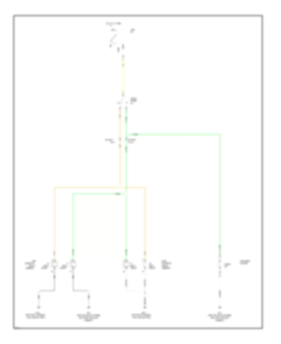
Headlight Wiring Diagram, without Fog Lamps for Chevrolet Beretta Z26 1995
List of elements for Headlight Wiring Diagram, without Fog Lamps for Chevrolet Beretta Z26 1995:
- (forward lights harness,
- (left front of engine
- Assembly
- Assembly)
- B/h conn
- Beam
- Cluster
- Comp, near battery)
- Composite
- Dimmer
- G100
- G101
- Head
- Headlt
- Hi beam
- Hot at all times
- Ind
- Instrument
- Left
- Light
- Near left headlight
- Near right headlight
- Off
- Park
- Pin a2
- Pin f1
- Right
- Tan
HORN
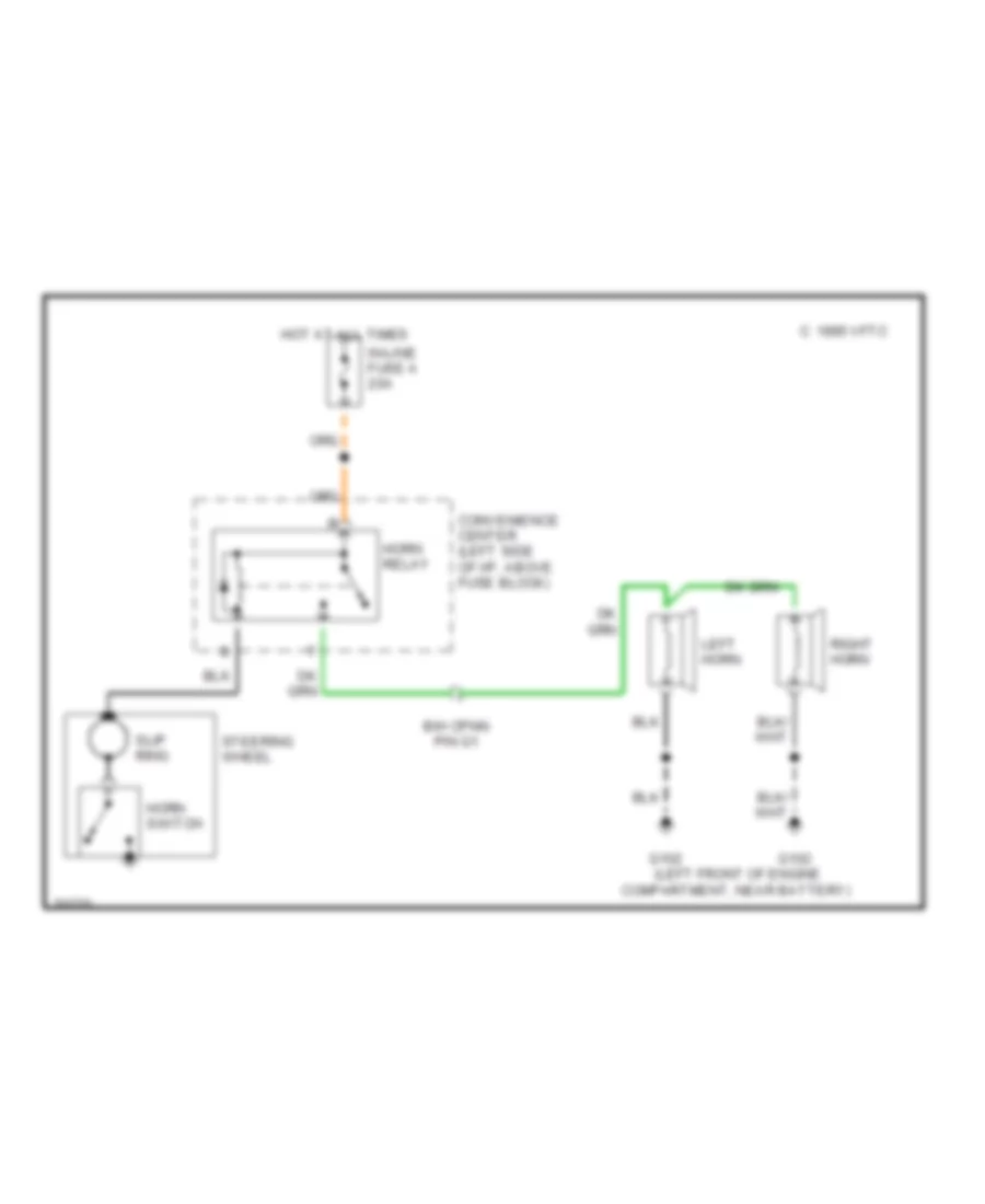
Horn Wiring Diagram for Chevrolet Beretta Z26 1995
List of elements for Horn Wiring Diagram for Chevrolet Beretta Z26 1995:
- (left front of engine
- 1995 vftc c
- B/h cpnn pin g1
- Compartment, near battery)
- Convenience center (left side of i/p, above fuse block)
- G102
- Horn relay
- Horn switch
- Hot at all times
- In-line fuse a 20a
- Left horn
- Right horn
- Slip ring
- Steering wheel
INSTRUMENT CLUSTER
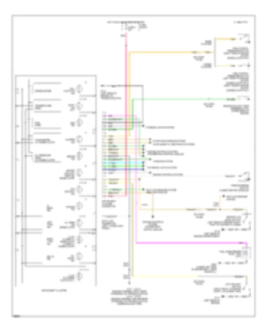
Instrument Cluster Wiring Diagram for Chevrolet Beretta Z26 1995
List of elements for Instrument Cluster Wiring Diagram for Chevrolet Beretta Z26 1995:
- (vin 4)
- (vin m)
- 1995 vftc c
- Abs ind
- Air bag ind
- Anti-lock brakes system
- Anti-lock brakes system (abs lamp module)
- B/h conn pin b5
- B/h conn pin d4
- B/h conn pin e4
- B/h conn pin e5
- Base cluster
- Belts ind
- Brake fluid level switch (left rear of engine compt, part of master cylinder)
- Brake ind
- Charge ind
- Data link connector (left lower hush panel)
- Engine controls system
- Engine controls system (powertrain contrl module)
- Engine controls system (powertrain control module)
- Engine coolant temp ind (base clstr)
- Engine coolant temp sender/switch (upper rear of engine)
- Exterior lights system
- Fuel gage
- Fuel gage sender (fuel tank unit)
- Fuel pump/oil pressure switch (left front of engine block) (gages clstr vin m) (right side of engine block) (gages clstr vin 4)
- Fuel pump/oil pressure switch (right side of engine block) (base clstr vin m)
- Fuse 2 20a
- Fuse block
- G114 (left rear of engine)
- G114 (left rear of engine, on transaxle stud)
- G116 (left rear of engine compartment)
- G117 (engine harness, right rear of engine, on transaxle stud) g115 (engine harness, center rear of engine, on transaxle stud under exhaust pipe)
- G300 (under left side of driver seat, near door sill)
- Gages cluster
- Hi beam ind
- Hot in run, bulb test or start
- Illum (2 used w/ base clstr 3 used w/ gages clstr)
- Illum (w/ gages clstr only)
- Instrument cluster
- Instrument cluster connector
- Interior lights system
- Left turn ind
- Low coolant ind
- Low coolant switch (right front of engine compt, on surge tank)
- Mal- function ind
- Oil level ind
- Oil pres ind (base clstr)
- Oil pressure gage (w/ gages clstr)
- Parking brake switch (under center console)
- Pnk
- Right turn ind
- Shift ind (m/t)
- Speedometer
- Starting/charging system
- Tachometer (w/ gages clstr)
- Tan
- Temperature gage
- Vin m
- Warning system
INTERIOR LIGHTS
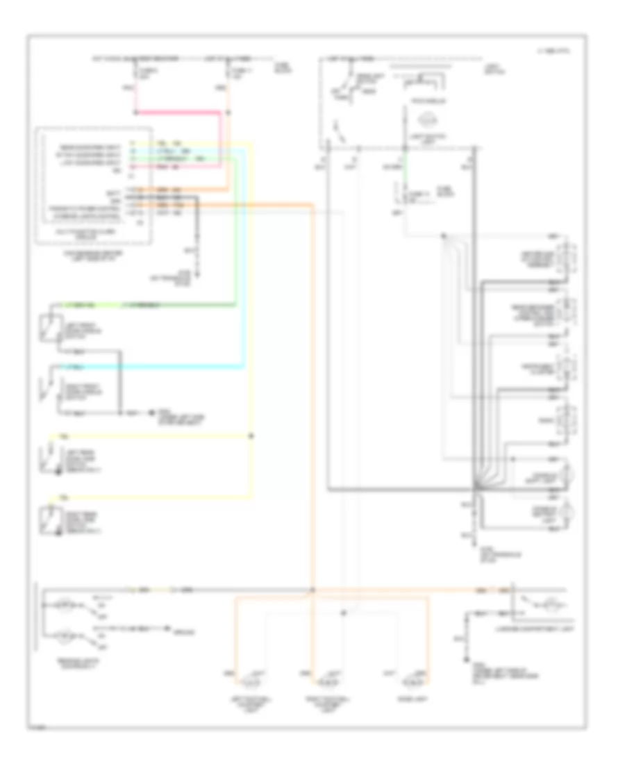
Interior Light Wiring Diagram for Chevrolet Beretta Z26 1995
List of elements for Interior Light Wiring Diagram for Chevrolet Beretta Z26 1995:
- 1995 vftc c
- Batt
- Console ashtray light
- Console shift light
- Convenience center (left side of i/p)
- Dome light
- Fuse 11 15a
- Fuse 13 3a
- Fuse 9 20a
- Fuse block
- G129 (on transaxle stud)
- G300 (under left side of driver seat)
- G300 (under left side of driver seat, near door sill)
- Gnd
- Ground
- Head
- Headlight switch
- Heater and a/c control assembly
- Hot at all times
- Hot in run, bulb test or start
- Ign
- Instrument cluster
- Interior lights control
- L fnt door open input
- Left footwell courtesy light
- Left front door handle switch
- Left rear door jamb switch (sedan only)
- Light switch
- Light switch light
- Luggage compartment light
- Multi-function alarm module
- Off
- Parasitic power control
- Park
- Pnk
- Pwm module
- Radio
- Reading lights (coupe only)
- Rear defogger control and wiper/washer switch
- Rear door open input
- Right footwell courtesy light
- Right front door handle switch
- Right rear door jamb switch (sedan only)
- Rt fnt door open input
PASSIVE RESTRAINTS
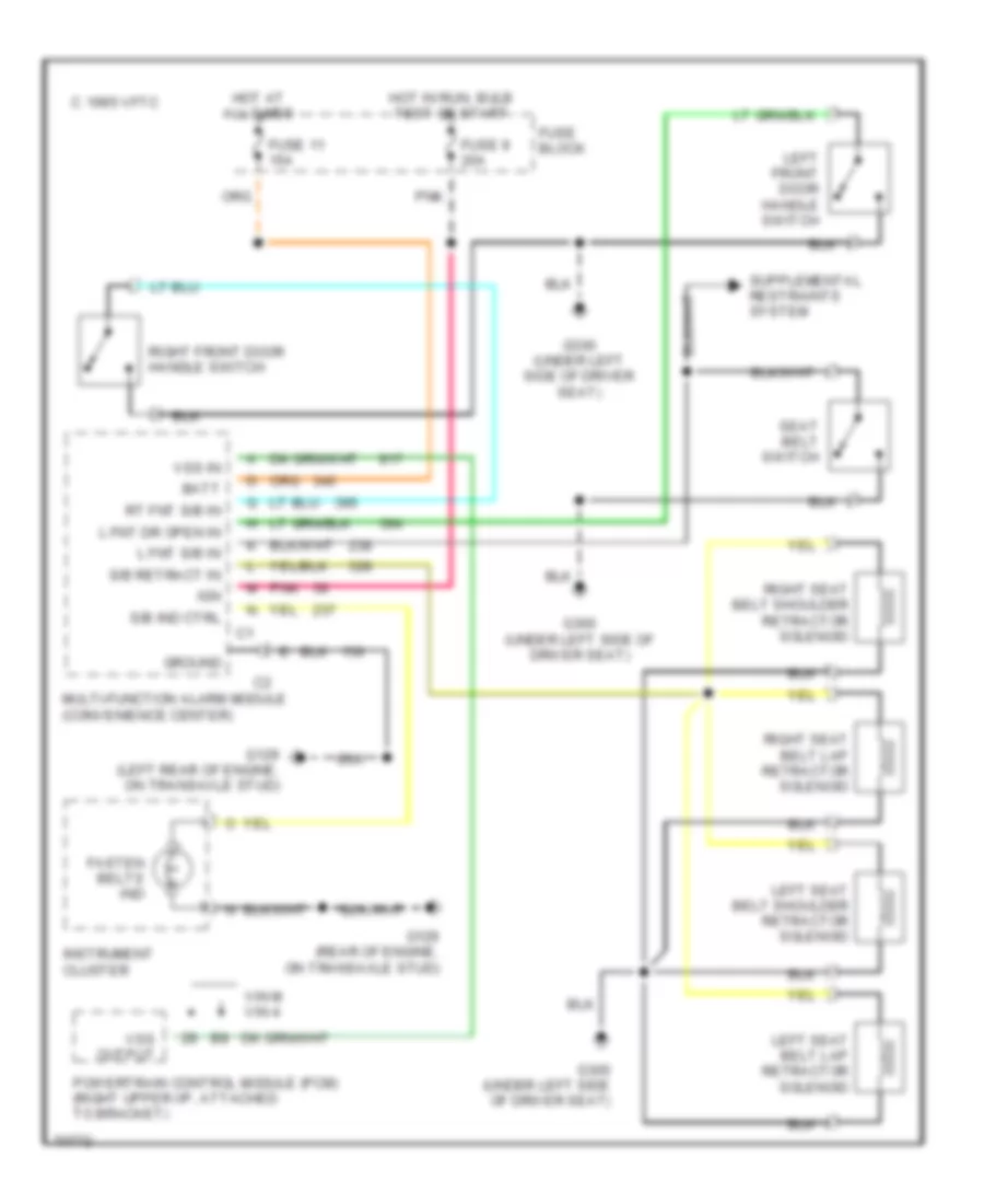
Passive Restraint Wiring Diagram for Chevrolet Beretta Z26 1995
List of elements for Passive Restraint Wiring Diagram for Chevrolet Beretta Z26 1995:
- 1995 vftc c
- Batt
- Fasten belts ind
- Fuse 11 15a
- Fuse 9 20a
- Fuse block
- G129 (left rear of engine, on transaxle stud)
- G129 (rear of engine, on transaxle stud)
- G300 (under left side of driver seat)
- Ground
- Hot at all times
- Hot in run, bulb test or start
- Ign
- Instrument cluster
- L fnt dr open in
- L fnt s/b in
- Left front door handle switch
- Left seat belt lap retractor solenoid
- Left seat belt shoulder retractor solenoid
- Multi-function alarm module (convenience center)
- Pnk
- Powertrain control module (pcm) (right upper i/p, attached to bracket)
- Right front door handle switch
- Right seat belt lap retractor solenoid
- Right seat belt shoulder retractor solenoid
- Rt fnt s/b in
- S/b ind ctrl
- S/b retract in
- Seat belt switch
- Vin m vin 4
- Vss in
- Vss output
POWER DISTRIBUTION
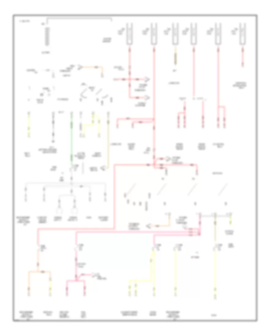
Power Distribution Wiring Diagram (1 of 3) for Chevrolet Beretta Z26 1995
List of elements for Power Distribution Wiring Diagram (1 of 3) for Chevrolet Beretta Z26 1995:
- #1, #5 & #9
- #10
- #13
- #14
- #16
- #2 & #6
- #4 & cb #12
- #7 & #11
- (fuse block)
- (left rear of engine,
- 10a
- 14 ga
- 15a
- 16 ga
- 1994 vftc c
- 20 ga
- 20a
- 25a
- 30a
- A/c/heater
- A10
- Above starter)
- Accy
- Alternator
- Arming
- Ashtray lt
- Assembly
- B/h
- B/h conn
- Bat
- Battery
- Block
- Blower
- Brake control
- Bulb test
- Cb #15
- Cluster
- Conn
- Console
- Control
- Control &
- Courtesy
- Daytime
- Details
- Diagnostic energy
- Dimmer
- Dimmer sw
- Door lock
- Electronic
- Engine
- Fan control
- Fog lt
- Fog lts
- From
- Fuel
- Fuel pump/
- Fus
- Fuse
- Fuse #7
- G114
- Head
- Headlt
- Ignition sw
- In-line fuse
- Injectors
- Instrument
- L4 vin 4
- Light sw
- Lighting
- Link a
- Link b
- Link c
- Link d
- Link e
- Link g
- Lock
- Lts
- Module
- Motor
- Not
- Not used
- Off
- Oil pres
- On ind
- Park
- Pin a4
- Pin a5
- Pin b4
- Pnk
- Pump
- Pwm module
- Radio
- Rear defogger
- Red
- Relay
- Reserve module
- Run
- Running lts
- Sender sw
- Sensor
- Shift lt
- Solenoid
- Start
- Starter
- Starting
- Sw lt
- System
- To fog lt
- To fuses
- To fuses #8,
- Used
- V6 vin m
- Wiper/washer
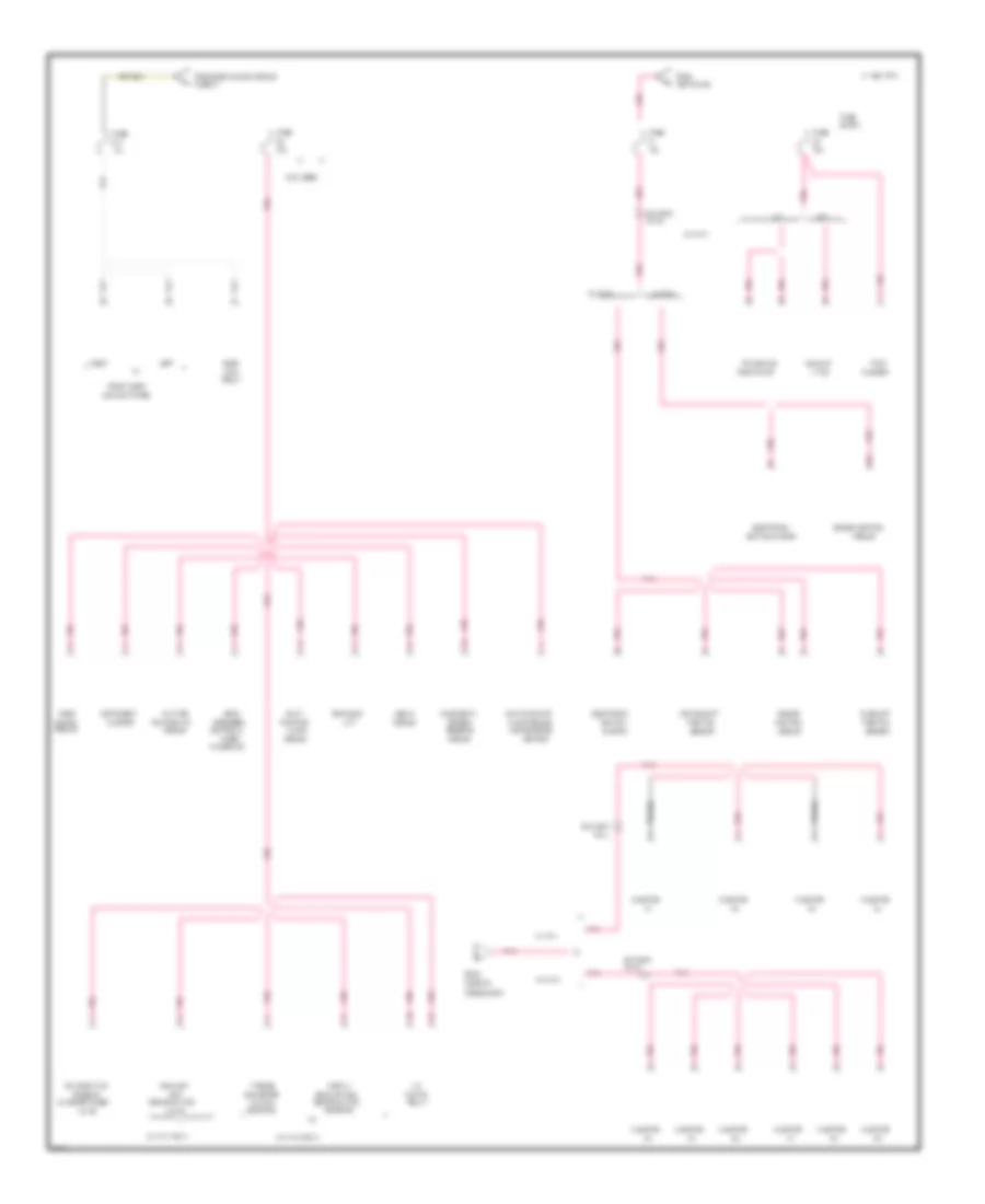
Power Distribution Wiring Diagram (2 of 3) for Chevrolet Beretta Z26 1995
List of elements for Power Distribution Wiring Diagram (2 of 3) for Chevrolet Beretta Z26 1995:
- #11
- (convenience
- (fuse block)
- (under left front
- (v6 vin m
- 10a
- 15a
- 1994 vftc c
- 2 door
- 20a
- 25a
- 30a
- 4 door
- A/c/heater
- Alarm
- Alternator
- Assembly
- B/h conn
- Block
- Brake
- Cb #12
- Center)
- Cig
- Compt
- Console
- Control
- Coupe
- Coupe w/o t96
- Daytime
- Daytime running
- Door lock
- Elect brake
- Electronic
- Flasher
- Fog lt
- From
- Function
- Fus link b
- Fus link d
- Fuse
- Fuse a
- G300
- Hazard
- Heated
- Horn rly
- Ignition sw
- In-line
- Left
- Left fnt
- Left front
- Left rear
- Left tail/stop &
- License
- License lt
- Light
- Light sw
- Lighter
- Lts module
- Luggage
- Marker lt
- Module
- Motor
- Multi-
- Multi-function
- Only)
- Oxygen
- Park/turn
- Pin b1
- Pin c4
- Pin g4
- Radio
- Red
- Relay
- Release
- Right
- Right fnt
- Right front
- Right rear
- Right tail/stop &
- Rly
- Running
- Seat, near door sill)
- Sedan
- Sensor
- Side marker
- Switch
- Temp valve
- To fuse #17
- Turn lts
- Window sw
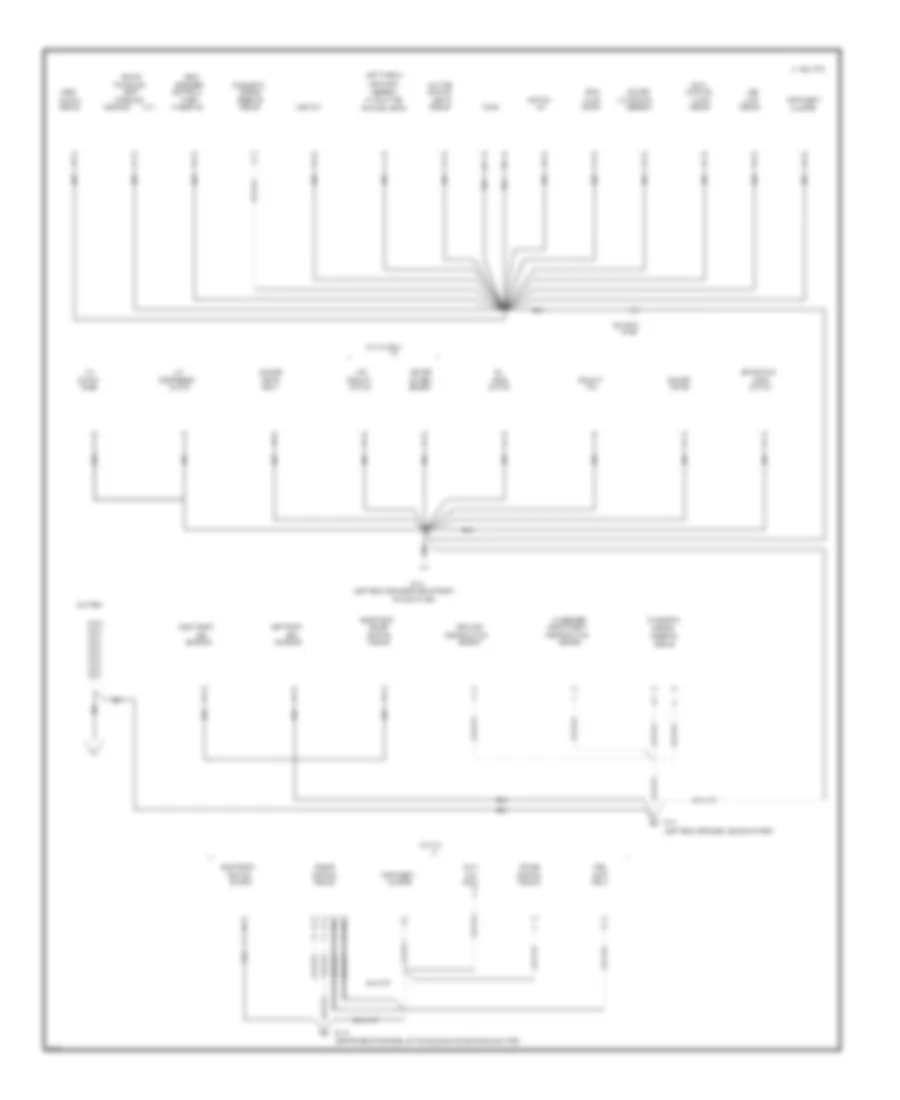
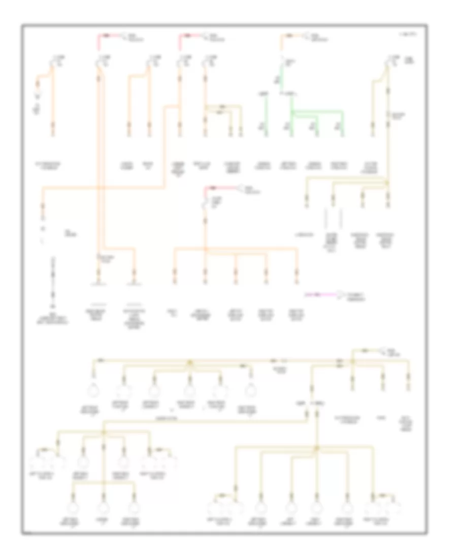
Power Distribution Wiring Diagram (3 of 3) for Chevrolet Beretta Z26 1995
List of elements for Power Distribution Wiring Diagram (3 of 3) for Chevrolet Beretta Z26 1995:
- #17
- (a/t)
- (convenience
- (fuse block)
- (l4 vin 4 only)
- (not used)
- (v6 vin m only)
- 10a
- 15a
- 1994 vftc c
- 20a
- A/c
- A/t
- Abs lp
- Alarm
- Alarm module
- B/h conn
- Back-up
- Block
- Brake sw
- Camshaft
- Canister purge
- Center)
- Cluster
- Clutch
- Control
- Control &
- Converter
- Crankshaft
- D16
- Daytime
- Defogger
- Diagnostic
- Digital
- Door
- Electronic
- Emission
- Energy
- Engine
- Engine control
- Evaporative
- Exhaust
- Exhaust gas
- Flasher
- From
- From door unlock module
- Front door
- Function
- Fuse
- Fuse #11
- Fuse #16
- Gas
- Ignition
- Ignition sw
- Ignition system
- Injector
- Instrument
- L4 vin 4
- Left
- Lock
- Lock switches
- Lt sw
- M/t
- Module
- Multi-
- Multi-function
- Pin a
- Pin d
- Pin f4
- Pnk
- Position
- Position sw
- Rear
- Recirculation
- Relay
- Reserve
- Right
- Running lts
- Sensor
- Solenoid
- System
- Torque
- Transaxle
- Turn
- Unlock
- V6 vin m
- Valve
- Washer sw
- Wiper/
POWER DOOR LOCKS
Power Door Lock Wiring Diagram for Chevrolet Beretta Z26 1995
List of elements for Power Door Lock Wiring Diagram for Chevrolet Beretta Z26 1995:
- (behind left lower kick panel)
- (left rear of engine, on transaxle stud)
- (notused)
- (vin 4)
- (vin 4) (vin m)
- (vin m)
- 1995 vftc c
- Auto door unlock module (rifght side of i/p, near derm module)
- Bat
- C2 c2
- Circuit breaker 15 30a
- Door lock
- Engine control module (right upper i/p attached to bracket)
- Engine control module (right upper i/p, attached to bracket)
- Engine controls system
- Fuse 10a
- Fuse 20a
- Fuse block
- G104 (left rear of engine compartment, on transaxle stud)
- G114
- G117 (right rear of engine on transaxle stud)
- G300 (below driver's seat)
- Gnd
- Hot at all times
- Hot in run, bulb test or start
- Ign
- In-line fuse a 20a
- Left door lock switch
- Left front door lock motor
- Left rear door lock motor (4-door only)
- Lock
- Lock relay
- Multi- function alarm module (in convenience center)
- Park/ neutral input
- Park/ neutral position switch (top right side of transaxle)
- Pnk
- Relay assembly
- Relay control
- Right front door lock motor
- Right rear door lock motor (4-door only)
- Right door lock switch
- Solid state
- Tan
- Unlock
- Unlock control
- Unlock relay
- Vehicle speed input
- Viin 4 with a/t
- Vin 4 w/ m/t
- Vin m
POWER WINDOWS
Power Window Wiring Diagram for Chevrolet Beretta Z26 1995
List of elements for Power Window Wiring Diagram for Chevrolet Beretta Z26 1995:
- 1995 vftc c
- 30a
- Circuit breaker 12
- Console window switch
- Fuse block
- G300 (below left front seat)
- Hot in run
- Left front power window motor
- One touch window down module
- Right front power window motor
- Tan
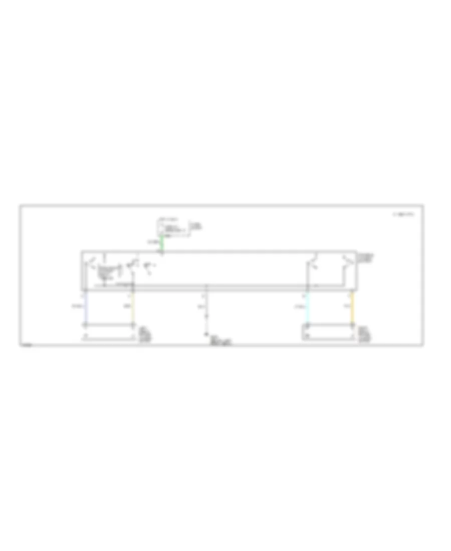
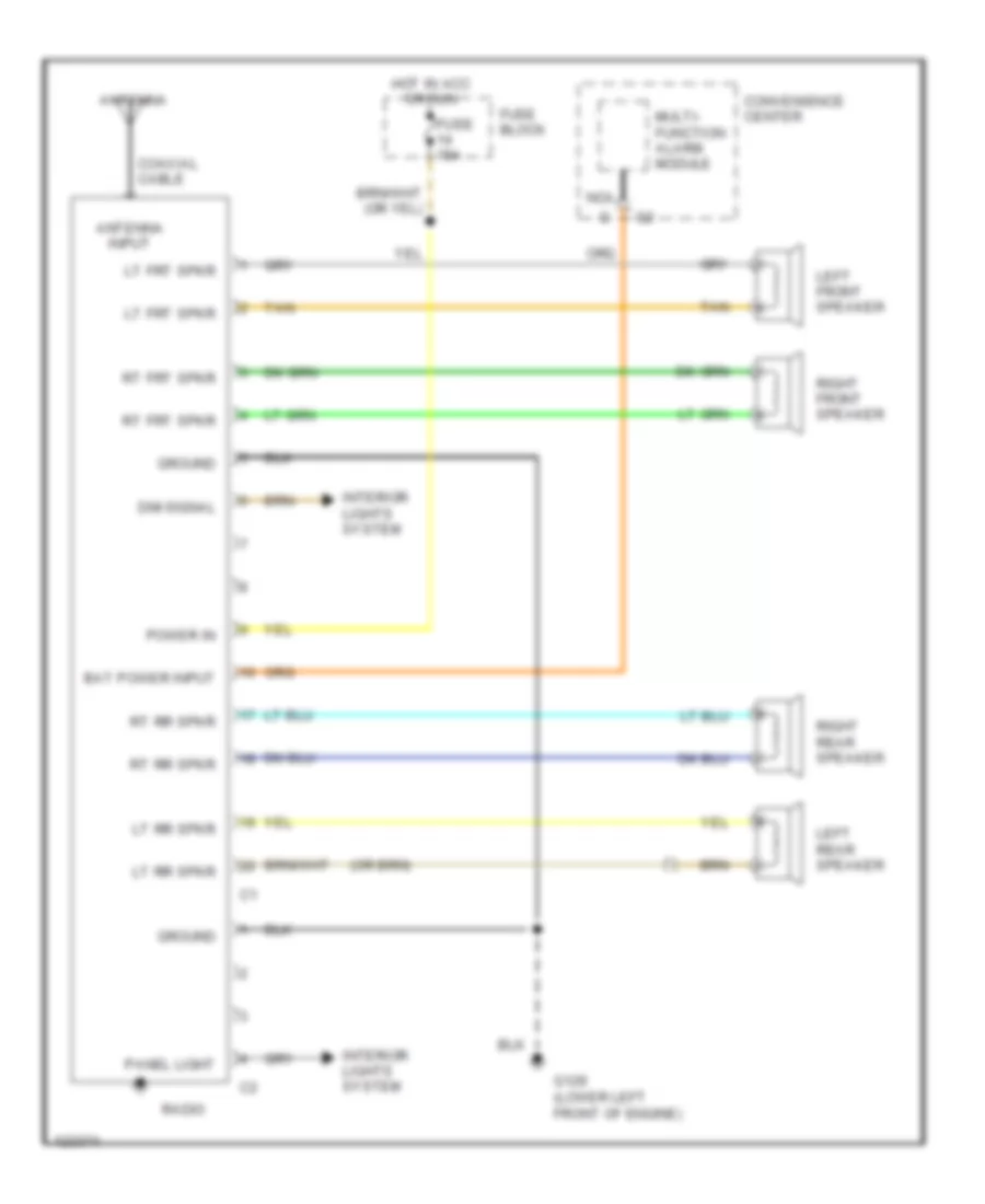
RADIO
Radio Wiring Diagrams for Chevrolet Beretta Z26 1995
List of elements for Radio Wiring Diagrams for Chevrolet Beretta Z26 1995:
- Antenna
- Antenna input
- Bat power input
- Coaxial cable
- Convenience center
- Dim signal
- Fuse 15a
- Fuse block
- G129 (lower left front of engine)
- Ground
- Hot in acc or run
- Interior lights system
- Left front speaker
- Left rear speaker
- Lt frt spkr
- Lt rr spkr
- Multi- function alarm module
- Nca
- Panel light
- Power in
- Radio
- Right front speaker
- Right rear speaker
- Rt frt spkr
- Rt rr spkr
- Tan
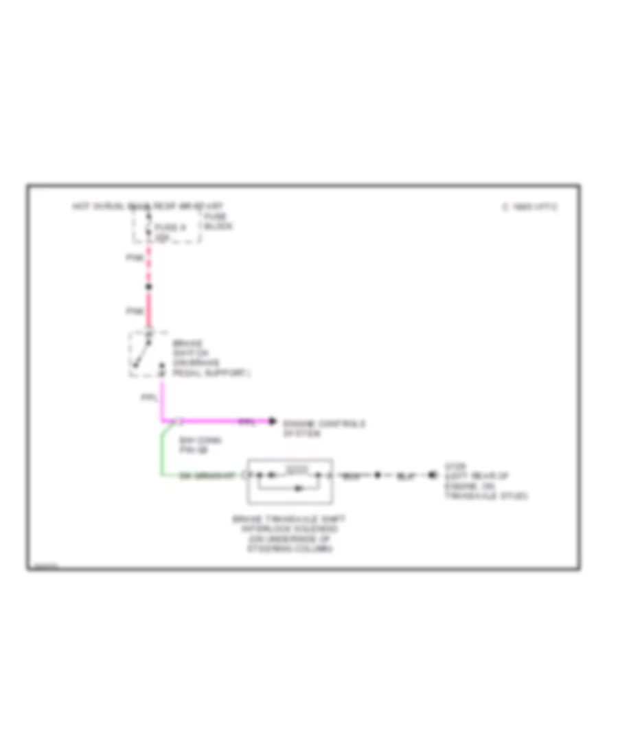
SHIFT INTERLOCKS
Shift Interlock Wiring Diagram for Chevrolet Beretta Z26 1995
List of elements for Shift Interlock Wiring Diagram for Chevrolet Beretta Z26 1995:
- 1995 vftc c
- B/h conn pin g8
- Brake switch (on brake pedal support)
- Brake transaxle shift interlock solenoid (on underside of steering column)
- Engine controls system
- Fuse 9 20a
- Fuse block
- G129 (left rear of engine, on transaxle stud)
- Hot in run, bulb test or start
- Pnk
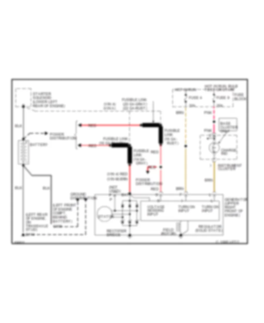
STARTING/CHARGING
Charging Wiring Diagram for Chevrolet Beretta Z26 1995
List of elements for Charging Wiring Diagram for Chevrolet Beretta Z26 1995:
- (16 ga-black) red
- (left front of engine compt, behind battery)
- (left rear of engine, on transaxle stud)
- (not used) p
- (solid state)
- (vin 4)
- (vin 4) (vin a)
- (vin m)
- 10a
- 1995 vftc c
- 20a
- Base cluster only
- Bat
- Battery
- Charge ind.
- Field (rotor)
- Fuse 4
- Fuse 9
- Fuse block
- Fusible link
- Fusible link (14 ga- gray)
- Fusible link (16 ga- rust)
- Fusible link (20 ga-gray) (22 ga-rust)
- G100
- G114
- Generator (upper right front of engine)
- Ground distribution
- Hot in run
- Hot in run, bulb test or start
- Instrument cluster
- Pnk
- Power distribution
- Rectifier bridge
- Red
- Regulator
- Starter solenoid (lower left rear of engine)
- Stator
- Turn on input
- Voltage sensing input
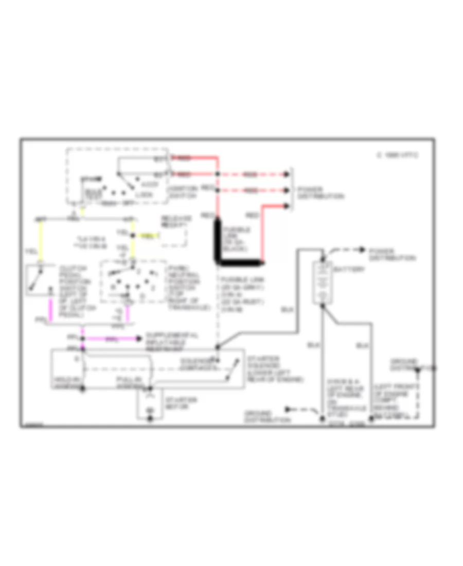
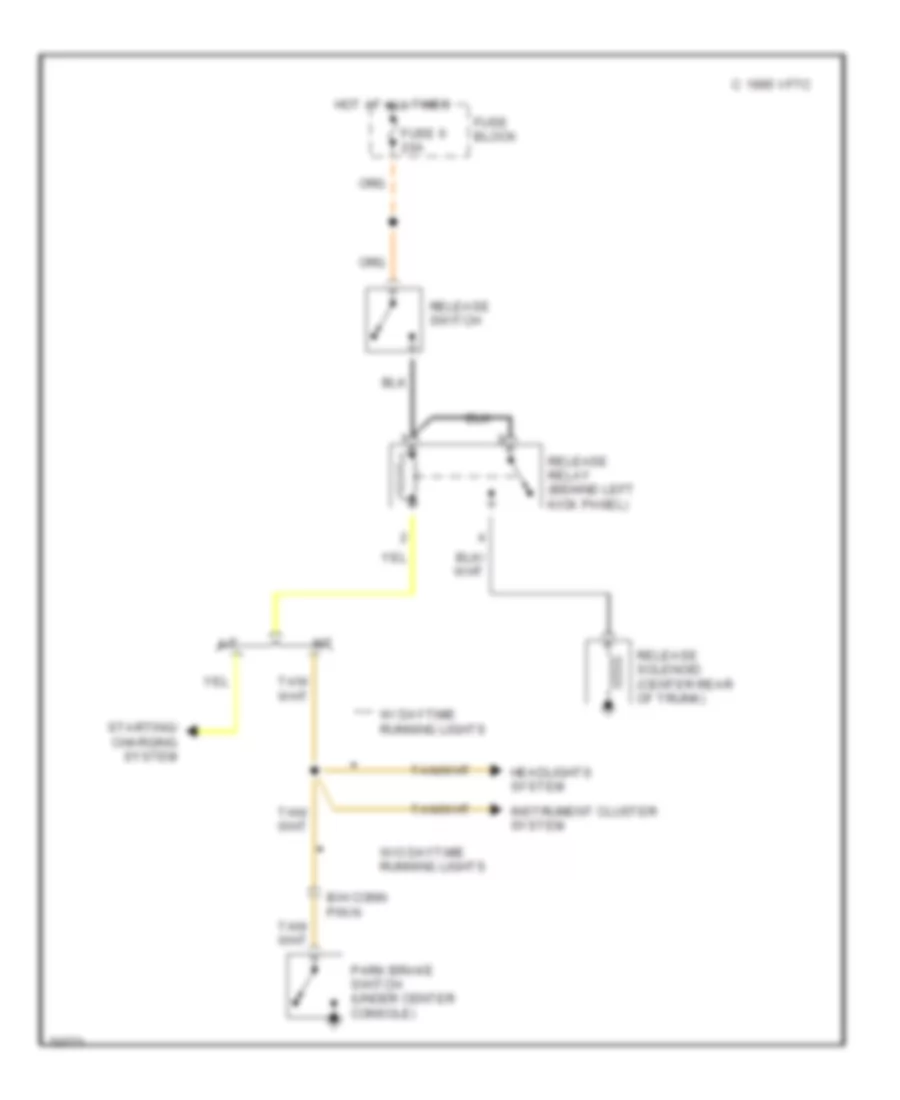
Starting Wiring Diagram for Chevrolet Beretta Z26 1995
List of elements for Starting Wiring Diagram for Chevrolet Beretta Z26 1995:
- (left front of engine compt, behind battery)
- (vin m & 4- left rear of engine, on transaxle stud)
- *l4 vin 4 **v6 vin m
- 1995 vftc c
- A/t
- Accy
- Battery
- Bulb test
- Clutch pedal position switch (left of i/p, left of clutch pedal)
- F * **
- Fusible link (16 ga- black)
- Fusible link (20 ga-gray) (vin 4) (22 ga-rust) (vin m)
- G * **
- G100
- G114
- Ground distribution
- Hold-in winding
- Ignition switch
- Lock
- M/t
- Off
- Park/ neutral position switch (top right of transaxle)
- Power distribution
- Pull-in winding
- Red
- Release relay
- Run
- Solenoid contacts
- Start
- Starter motor
- Starter solenoid (lower left rear of engine)
SUPPLEMENTAL RESTRAINTS
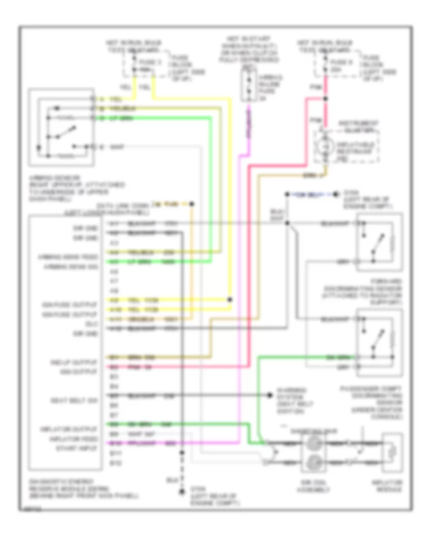
Supplemental Restraint Wiring Diagram for Chevrolet Beretta Z26 1995
List of elements for Supplemental Restraint Wiring Diagram for Chevrolet Beretta Z26 1995:
- A10
- A11
- A12
- Airbag in-line fuse 3a
- Arming sens feed
- Arming sens sig
- Arming sensor (right upper i/p, attatched to underside of upper dash panel)
- B10
- B11
- B12
- Diagnostic energy reserve module (derm) (behind right front kick panel)
- Dlc
- Forward discriminating sensor (attached to radiator support)
- Fuse 3 10a
- Fuse 9 20a
- Fuse block (left side of i/p)
- G104 (left rear of engine compt)
- Hot in run, bulb test or start
- Hot in start when in p/n (a/t) or when clutch fully depressed (m/t)
- Ign fuse output
- Ign output
- Ind lp output
- Inflatable restraint ind
- Inflator feed
- Inflator module
- Inflator output
- Instrument cluster
- M data link conn (left lower hush panel)
- Nca
- Passenger compt discriminating sensor (under center console)
- Pnk
- Seat belt sw
- Shorting bar
- Sir coil assembly
- Sir gnd
- Start input
- Tan
- Warning system (seat belt switch)
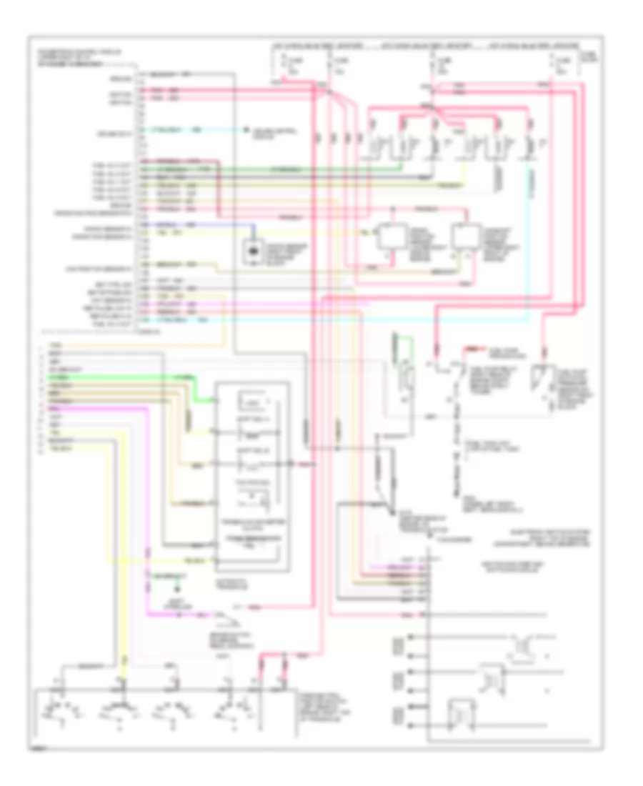
TRANSMISSION
2.2L
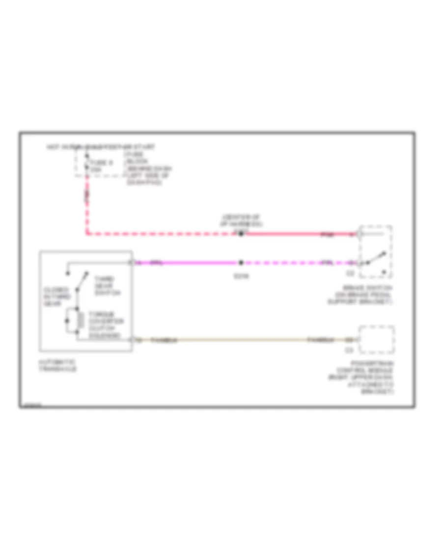
2.2L (VIN 4), Transmission Wiring Diagram for Chevrolet Beretta Z26 1995
List of elements for 2.2L (VIN 4), Transmission Wiring Diagram for Chevrolet Beretta Z26 1995:
- (center of i/p harness) s227
- Automatic transaxle
- Brake switch (on brake pedal support bracket)
- Closed in third gear
- Fuse 9 20a
- Fuse block (behind dash left side of dash pad)
- Hot in run, bulb test or start
- Pnk
- Powertrain control module (right upper dash, attached to bracket)
- S218
- Third gear switch
- Torque coverter clutch solenoid
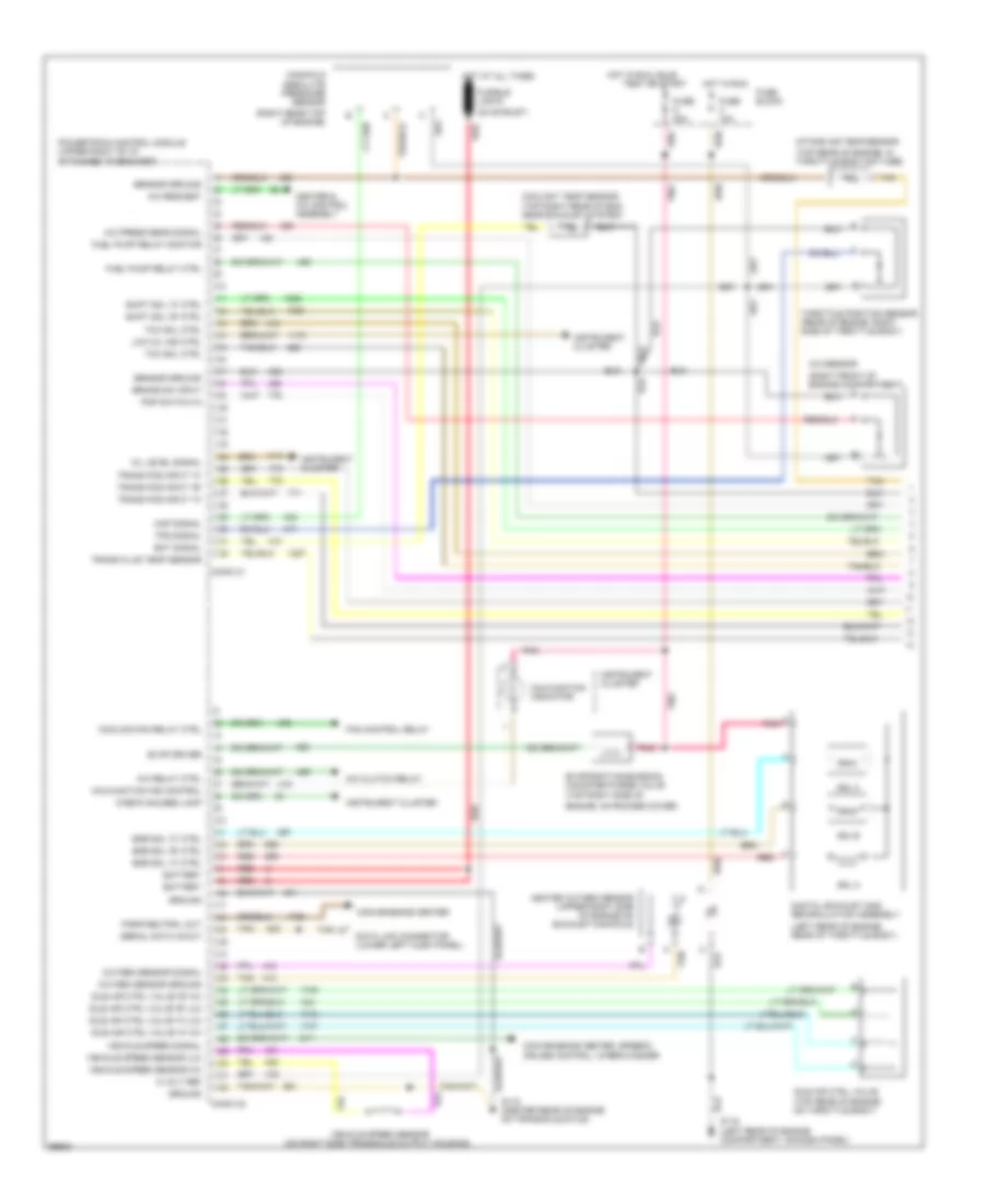
3.1L
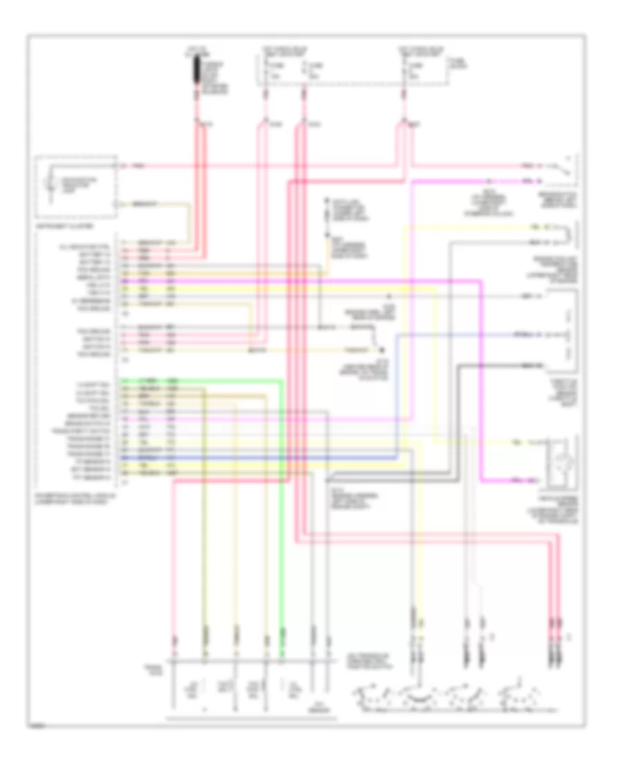
3.1L (VIN M), Transmission Wiring Diagram for Chevrolet Beretta Z26 1995
List of elements for 3.1L (VIN M), Transmission Wiring Diagram for Chevrolet Beretta Z26 1995:
- (on transaxle) park/neutral position switch
- 1-2 ctrl sol
- 1-2 shift sol
- 2-3 ctrl sol
- 2-3 shift sol
- 5v reference
- Battery in
- Brake switch (behind left side of dash)
- Brake switch in
- Data link connector (under left side of dash)
- Ect sensor in
- Engine coolant temperature sensor (upper right rear of engine)
- Fuse 15a
- Fuse 20a
- Fuse block
- Fusible link e (22 ga- rust) (starter solenoid)
- G115 (center rear of engine, on trans- axle stud)
- Hot at all times
- Hot in run, bulb test or start
- Ignition in
- Instrument cluster
- Malfunction indicator lamp
- Mil indicator ctrl
- Nca
- Pcm ground
- Pnk
- Powertrain control module (under right side of dash)
- Red
- S103
- S112 (engine harness, left side of engine compt)
- S115
- S120 (engine harn, left rear of engine)
- S126
- S178
- S179
- S207 (i/p harness, upper right side of dash)
- S218 (i/p harness, lower right side of steering column)
- S227
- Sensor return
- Serial data
- Tan
- Tcc pwm sol
- Tcc sol
- Tft sensor
- Tft sensor in
- Throttle position sensor (throttle body)
- Tp sensor in
- Trans parity switch
- Trans range "a"
- Trans range "b"
- Trans range "c"
- Trans- axle
- Vehicle speed sensor (lower right rear of engine compt, on transaxle)
- Vss hi in
- Vss lo in
TRUNK, TAILGATE, FUEL DOOR
Trunk Release Wiring Diagram for Chevrolet Beretta Z26 1995
List of elements for Trunk Release Wiring Diagram for Chevrolet Beretta Z26 1995:
- 1995 vftc c
- A/t
- B/h conn pin n
- Fuse 6 20a
- Fuse block
- Headlights system
- Hot at all times
- Instrument cluster system
- M/t
- Park brake switch (under center console)
- Release relay (behind left kick panel)
- Release solenoid (center rear of trunk)
- Release switch
- Starting/ charging system
- W/ daytime running lights
- W/o daytime running lights
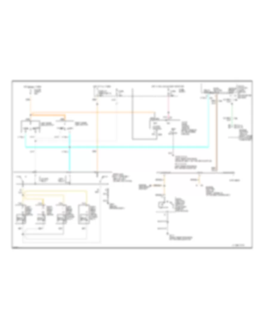
WARNING SYSTEMS
Warning System Wiring Diagrams for Chevrolet Beretta Z26 1995
List of elements for Warning System Wiring Diagrams for Chevrolet Beretta Z26 1995:
- (left side of i/p, above fuse block)
- (left side of i/p, right of steering column)
- (v6 vin m) (l4 vin 4)
- 1995 vftc c
- A nca
- A/t only
- Bat
- Battery
- C2 c2
- Convenience center
- Daytime running lights module (above glove box)
- Engine control module (under right side of i/p at shroud)
- Exterior lights system
- Fasten belts indicator
- Fasten belts indicator control
- Fuse 15a
- Fuse 20a
- Fuse block
- G104 (left rear of engine compartment)
- G130 (on transaxle stud)
- G300 (under left front seat)
- Ground
- Head
- Hot at all times
- Hot in run, bulb test or start
- Ignition
- Ignition switch
- Input
- Instrument cluster
- Key in ignition
- Left rear door jamb switch
- Left front door
- Left front door handle switch
- Lights on input
- Lights-on output
- Multi- function alarm module
- Nca
- Nca d
- Off
- Open input
- Parasitic pwr ctrl
- Park
- Park/neutral position switch (vin 4) powertrain control module (vin m)
- Pnk
- Radio
- Rear door open input
- Right front door
- Right front door handle switch
- Right rear door jamb switch
- Seat belt
- Seat belt switch (under center console)
- Turn flasher
- Turn signal input
- Turn/hazard- headlight switch assembly
- Vehicle speed input
- Vehicle speed output
WIPER/WASHER
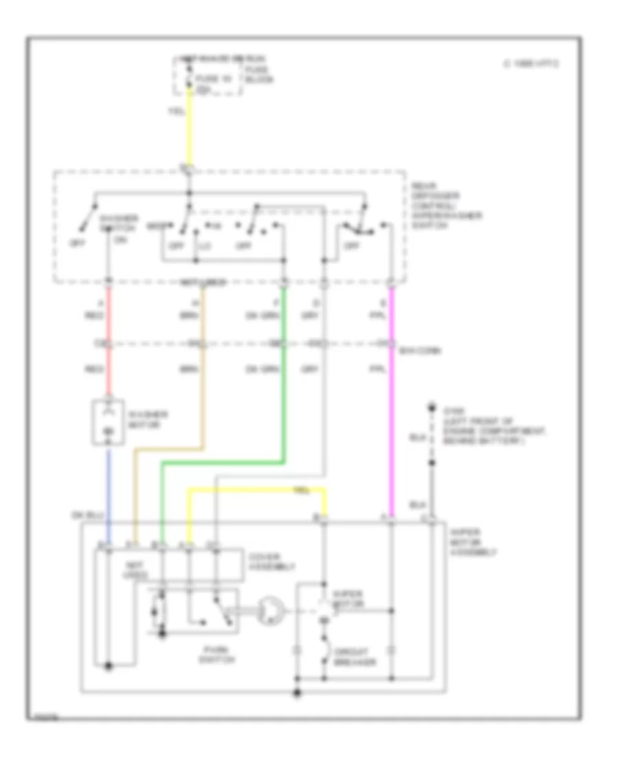
2-Speed Wiper/Washer Wiring Diagram for Chevrolet Beretta Z26 1995
List of elements for 2-Speed Wiper/Washer Wiring Diagram for Chevrolet Beretta Z26 1995:
- 1995 vftc c
- B/h conn
- Circuit breaker
- Cover assembly
- Fuse 10 25a
- Fuse block
- G100 (left front of engine compartment, behind battery)
- Hot in acc or run
- Mist
- Not used
- Off
- Park switch
- Rear defogger control/ wiper/washer switch
- Red
- Washer motor
- Washer switch
- Wiper motor
- Wiper motor assembly
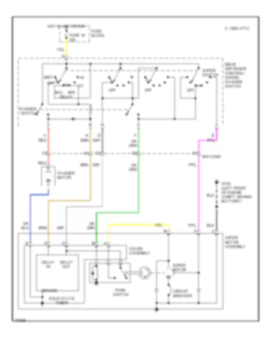
Interval Wiper/Washer Wiring Diagram for Chevrolet Beretta Z26 1995
List of elements for Interval Wiper/Washer Wiring Diagram for Chevrolet Beretta Z26 1995:
- 1995 vftc c
- B/h conn
- Circuit breaker
- Cover assembly
- Delay
- Delay in
- Delay out
- Fuse 10 25a
- Fuse block
- G100 (left front of engine compt, behind battery)
- Ground
- Hot in acc or run
- Max
- Min
- Mist
- Off
- Park switch
- Rear defogger control/ wiper/ washer switch
- Red
- Solid state timer
- Washer motor
- Washer switch
- Wiper motor
- Wiper motor assembly
- Wiper switch

 Čeština
 Dansk
Dansk Deutsch
 Ελληνικά
 English
 English
 Español
 Suomi
Suomi Français
 Français
 עברית
עברית Hrvatski
 Magyar
 Italiano
 日本語
日本語 한국어
한국어 Nederlands
 Português
 Português
 Română
 Русский
 Slovenčina
 Slovenščina
 Svenska
 Türkçe
 中文 (中国)