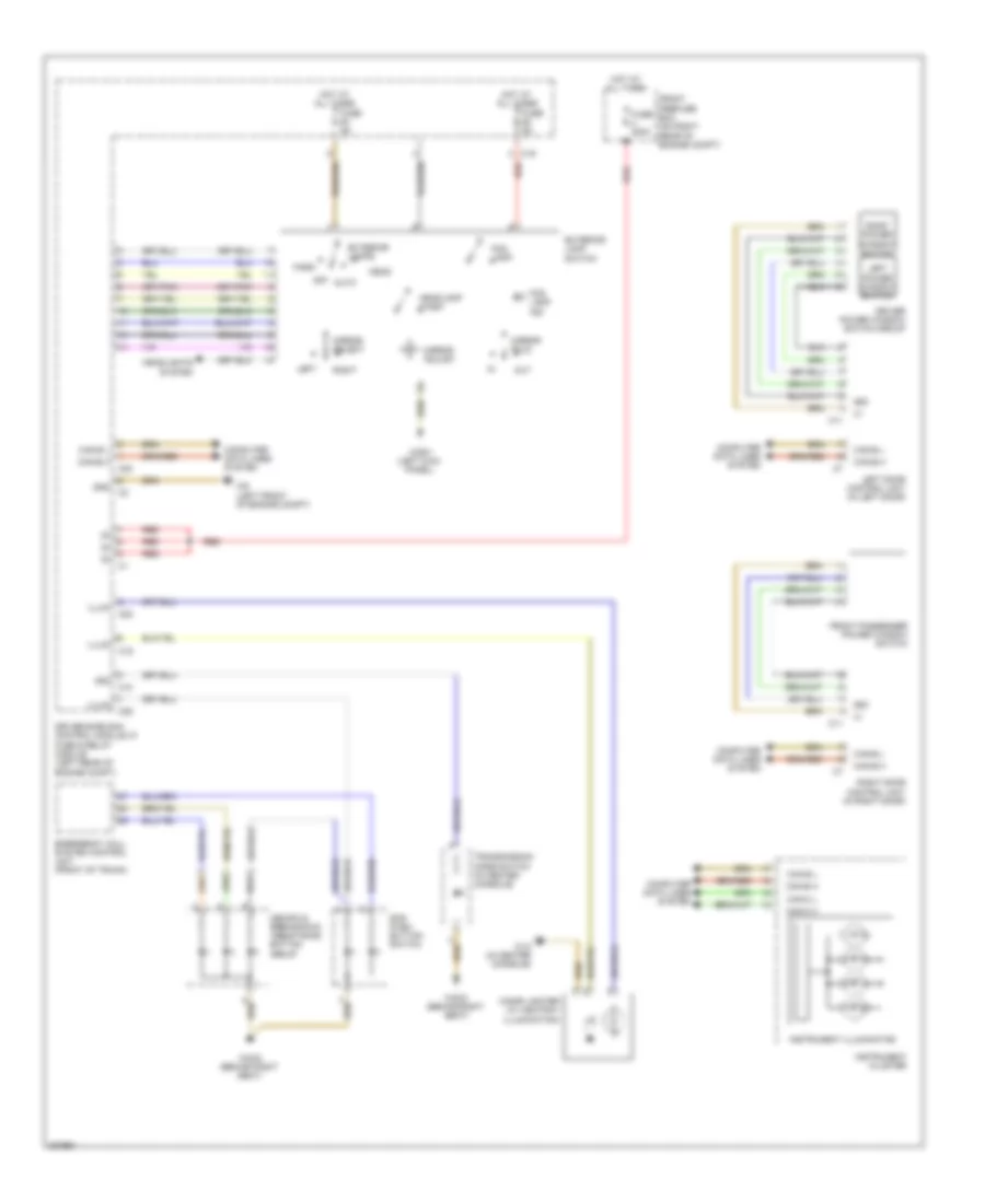
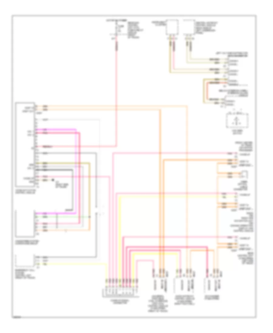
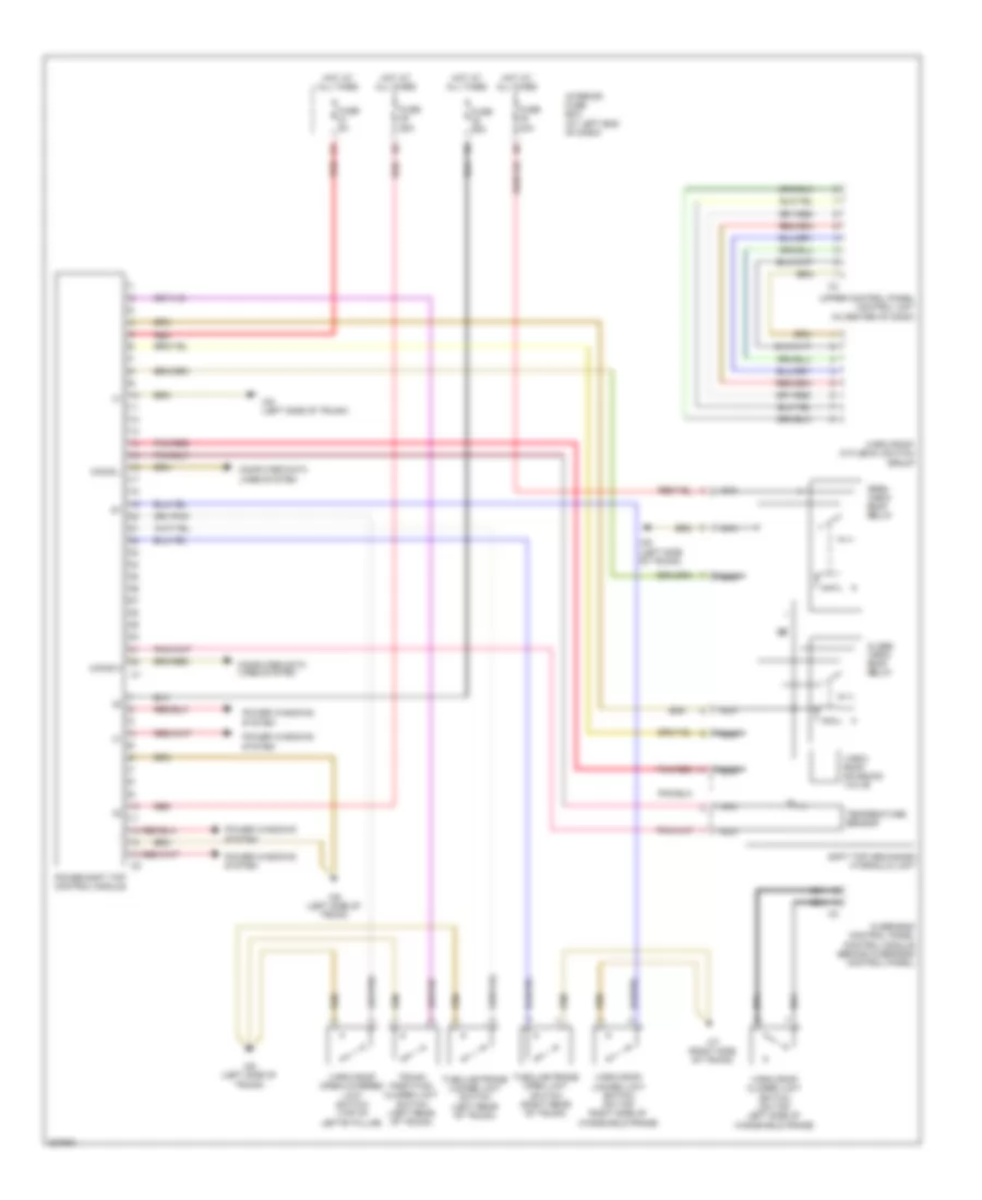
AIR CONDITIONING
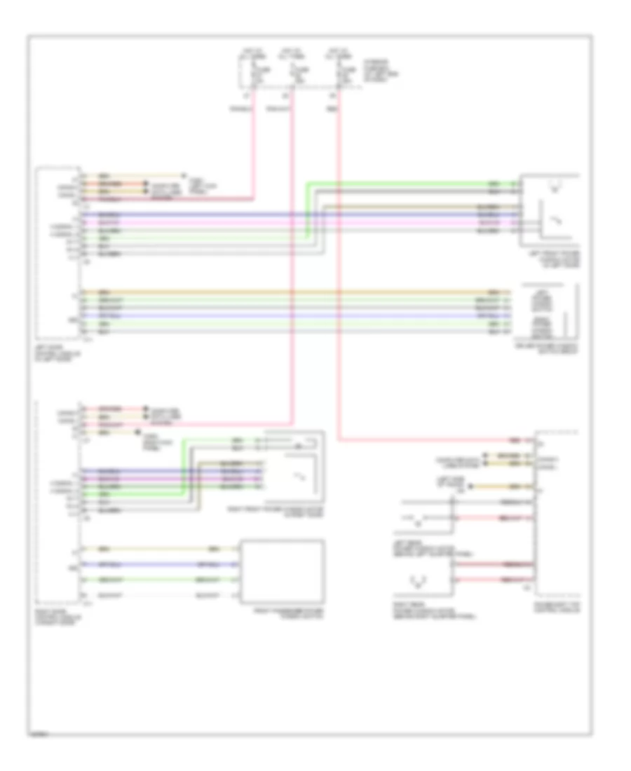
Automatic A/C Wiring Diagram for Mercedes-Benz SLK350 2005
 https://portal-diagnostov.com/license.html
Automotive Electricians Portal FZCO
Automotive Electricians Portal FZCO
https://portal-diagnostov.com/license.html
https://portal-diagnostov.com/license.html
Automotive Electricians Portal FZCO
Automotive Electricians Portal FZCO
List of elements for Automatic A/C Wiring Diagram for Mercedes-Benz SLK350 2005:
- (at left footwell)
- (right kick panel) w29/2
- (right rear of engine compt) duovalve
- 12v
- A/c compressor (left front of engine compt)
- Ac recirculation unit (behind right side of dash)
- Blower motor
- C-aac (k-kla) multifunction sensor (if equipped) (right rear of engine compt)
- C15
- C18
- C23
- Can-b h
- Can-b l
- Can-ch
- Can-cl
- Comfort aac pushbutton control module
- Common
- Computer data lines system
- Coolant circulation pump (right front of engine compt)
- Coolant temperature sensor (left rear of engine)
- Data
- Driver-side sam control module w/ fuse & relay module (left rear of engine compt)
- Electric suction fan engine & a/c with integrated control (front of engine compartment)
- Engine controls system
- Evap sens
- Evaporator temperature sensor (behind dash, left of center)
- Fresh air flaps actuator (w/ comfort aac) (behind center of dash)
- Fresh air/recirculated air flaps actuator motor (behind right side of dash)
- Front pre-fuse box (on right rear of engine compt)
- Fuse 125a
- Fuse 15a
- Fuse 40a
- Fuse 7.5a
- Hot at all times
- Hot in run or start
- In-car temperature sensor
- In-car temperature sensor fsn motor
- Interior fuse box (at left end of dash)
- Left & right defroster flaps actuator motor (at left footwell)
- Left & right footwell flaps actuator motor
- Left heat exchanger temperature sensor (behind center of dash)
- Me-sfi control module (on center of engine)
- Nca
- Nwg-m2
- Overhead control panel control module
- Purge control valve (left side of engine)
- R blwr select
- Rear window defroster switch
- Recirc unit
- Recirculated air switch
- Red
- Refrigerant pressure & temperature sensor (bottom left of condenser)
- Residual heat
- Right heat exchanger temperature sensor (behind center of dash)
- Sig
- Sun sensor
- Tmot
- W16/4 (on right front strut tower)
- W29/2 (right kick panel)
- W9 (left front of engine compt)
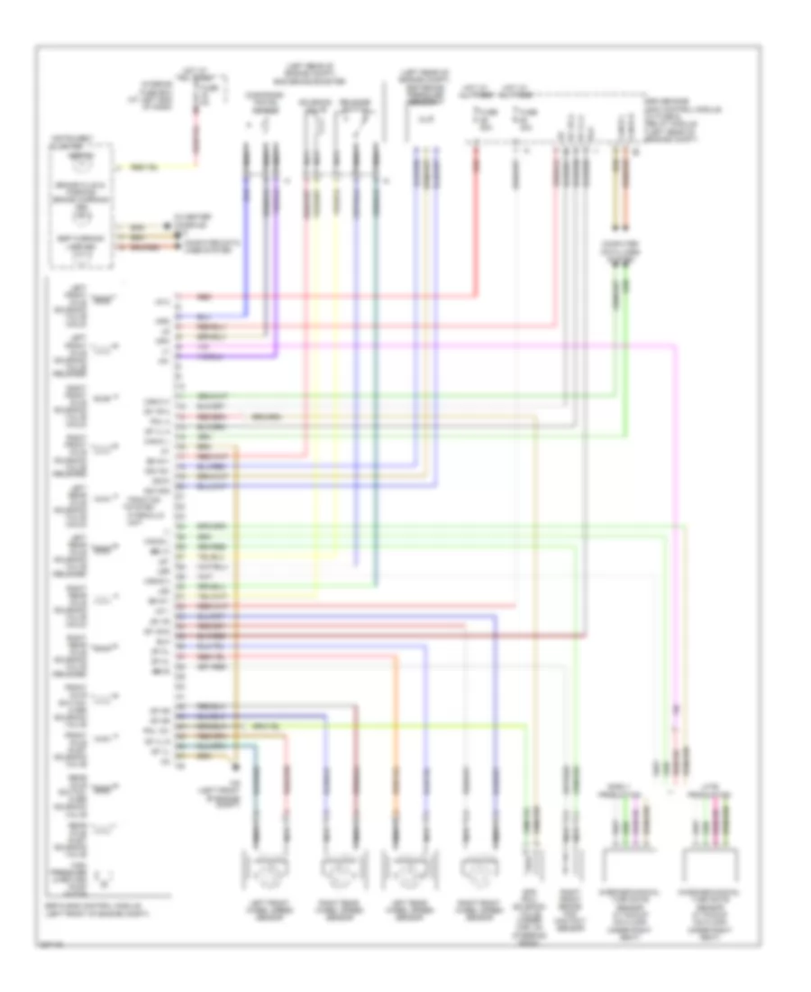
ANTI-LOCK BRAKES
Anti-lock Brakes Wiring Diagram for Mercedes-Benz SLK350 2005
List of elements for Anti-lock Brakes Wiring Diagram for Mercedes-Benz SLK350 2005:
- (+)
- (-)
- (in center console) w12
- (left rear of engine compt) bas brake booster
- (left rear of engine compt) esp brake pressure sensor 1
- +5v
- Abs ind
- Ba mv+
- Ba mv-
- Bbv m
- Bbvs
- Bla
- Brake fluid & parking brake warning ind
- Can-b h
- Can-b l
- Can-c h
- Can-c l
- Can-s h
- Can-s l
- Computer data lines system
- Df hl
- Df hr
- Df vl
- Df vl a
- Df vl s
- Df vr
- Df vr a
- Df vr s
- Dg1+5v
- Dg1-sig
- Dg1m
- Diaphragm travel sensor
- Driver-side sam control module w/ fuse & relay module (left rear of engine compt)
- Early production
- Esp & bas control module (left front of engine compt)
- Esp warning lamp ind
- Front axle inlet solenoid valve
- Front axle switch- over solenoid valve
- Fuse 40a
- Fuse 50a
- Fuse 5a
- High pressure & return pump motor
- Hot at all times
- Instrument cluster
- Interior fuse box (at left end of dash)
- Late production
- Left front axle solenoid valve (hold)
- Left front axle solenoid valve (release)
- Left front wheel speed sensor
- Left rear axle solenoid valve (hold)
- Left rear axle solenoid valve (release)
- Left rear wheel speed sensor
- Ls1
- Ls2
- Lsr
- Micromechanical turn rate sensor ay pickup (on floor under right seat)
- Mpm
- Mps
- Nca
- Pml 12v
- Pml a
- Rear axle inlet solenoid valve
- Rear axle switch- over solenoid valve
- Red
- Release switch
- Right front axle solenoid valve (hold)
- Right front axle solenoid valve (release)
- Right front brake pad contact sensor
- Right front wheel speed sensor
- Right rear axle solenoid valve (hold)
- Right rear axle solenoid valve (release)
- Right rear wheel speed sensor
- Solenoid valve
- Sps (pml) solenoid valve (under car, on
- Steering rack)
- Traction system hydraulic unit
- Um 1
- Um 2
- W9 (left front of engine compt)
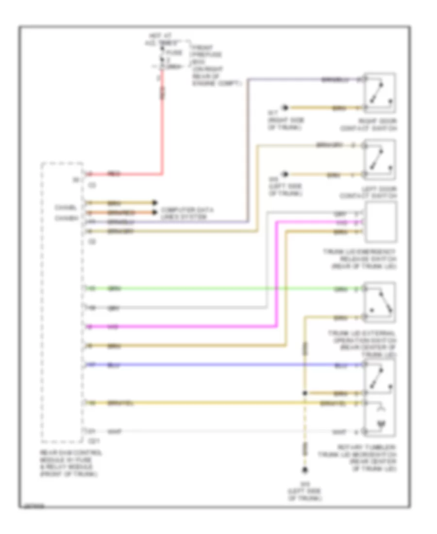
ANTI-THEFT
Anti-theft Alarm Wiring Diagram for Mercedes-Benz SLK350 2005
List of elements for Anti-theft Alarm Wiring Diagram for Mercedes-Benz SLK350 2005:
- (on right front strut tower) w16/4
- (under right seat, on floor) w19
- Alarm signal siren
- Ata (edw) hood switch (under right front of hood)
- C21
- Can b h
- Can b l
- Can c h
- Can c l
- Can-b h
- Can-b l
- Computer data lines system
- Early production
- Eis (ezs) control unit (left side of dash)
- Front pre-fuse box (on right rear of engine compt)
- Fuse 200a
- Hot at all times
- Late production
- Left door cl (zv) motor (in left door)
- Left door contact switch (on left "b" pillar)
- Left door control unit (in left door)
- Left ir receiver unit (left door handle)
- Rear sam control module w/ fuse & relay module (front of trunk)
- Red
- Right door cl (zv) motor (in right door)
- Right door contact switch (on right "b" pillar)
- Right door control unit (in right door)
- Right ir receiver unit (right door handle)
- Trunk lid contact switch
- Trunk lid emergency release switch (rear of trunk lid)
- Trunk lid external operation switch
- W32/2 (behind right seat)
- W32/2 (late production) (behind right seat)
- W6 (early production) (left side of trunk)
- W6 (left side of trunk)
- W7 (early production) (right side of trunk)
- W8/1 (late production)
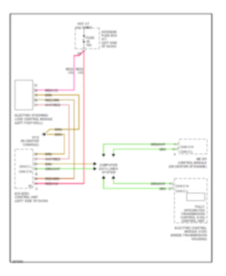
Drive Authorization System Wiring Diagram for Mercedes-Benz SLK350 2005
List of elements for Drive Authorization System Wiring Diagram for Mercedes-Benz SLK350 2005:
- Can c h
- Can c l
- Computer data lines system
- Eis (ezs) control unit (left side of dash)
- Electric control module (vgs) (inside transmission housing)
- Electric steering lock control module (left footwell)
- Fully integrated transmission control (vgs) control unit
- Fuse 15a
- Hot at all times
- Interior fuse box (at left end of dash)
- Me sfi control module (on center of engine)
- W12 (in center console)
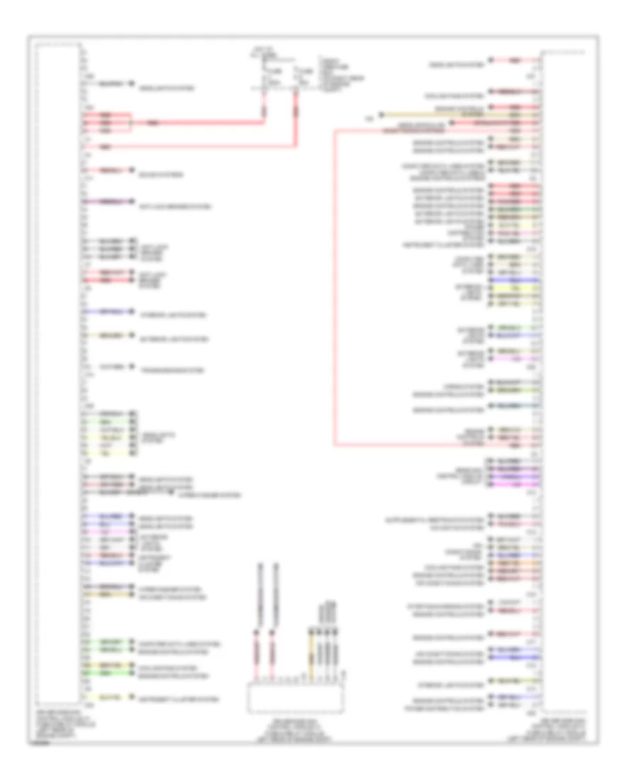
BODY CONTROL MODULES
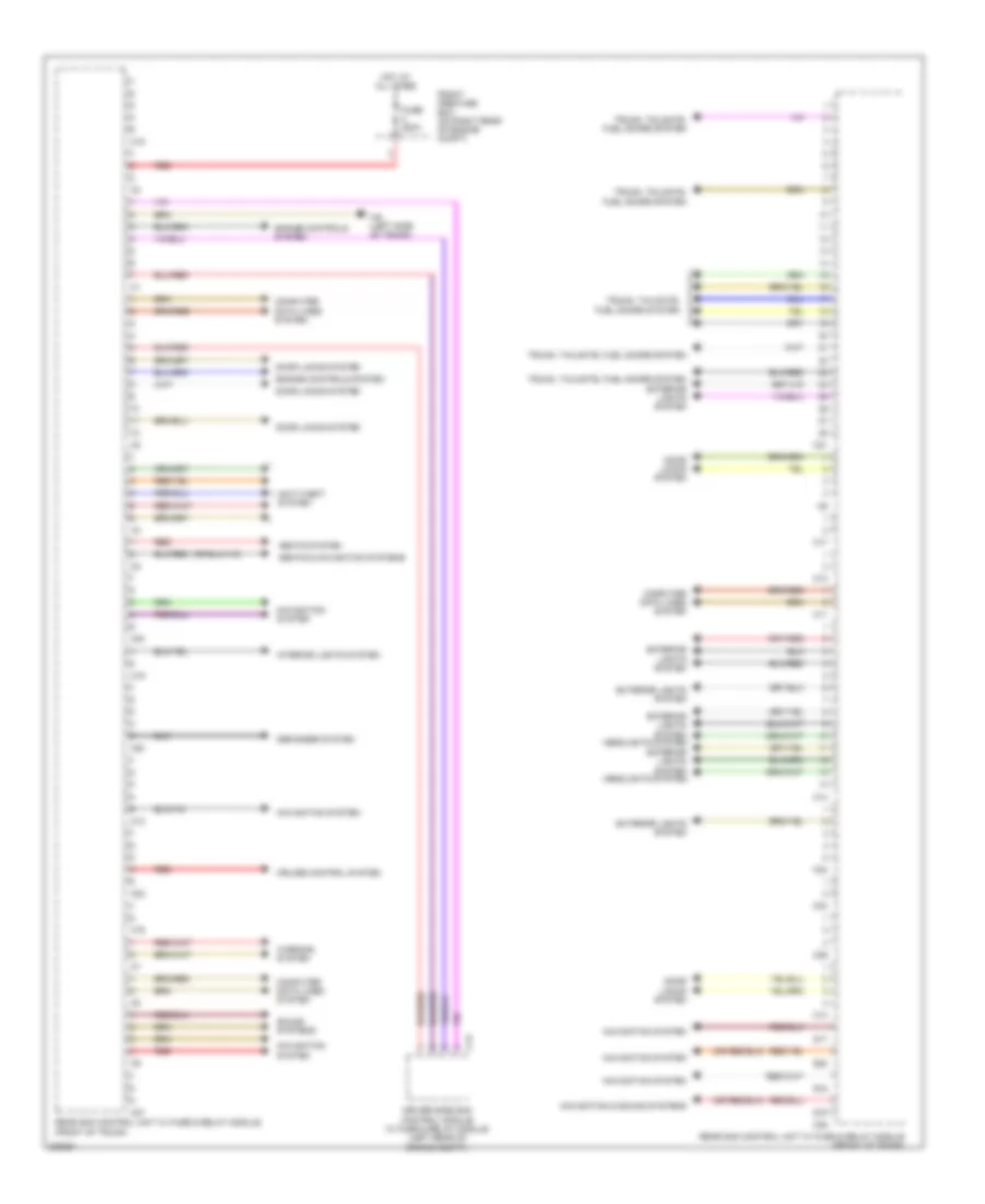
Driver"s Side SAM Control Module Wiring Diagram for Mercedes-Benz SLK350 2005
List of elements for Driver"s Side SAM Control Module Wiring Diagram for Mercedes-Benz SLK350 2005:
- Air conditioning system
- Anti-lock brakes system
- C10
- C11
- C12
- C13
- C14
- C15
- C16
- C17
- C18
- C19
- C20
- C21
- C22
- C23
- C24
- C25
- C26
- Computer data lines system
- Computer data lines system computer data lines & engine controls systems
- Cooling fans system
- Driver side sam control module w/ fuse & relay module (left rear of engine compt)
- Driver side sam control module w/ fuse & relay module (left rear of engine compt)
- Driver side sam control module w/ fuse & relay module left rear of engine compt
- Engine controls system
- Exterior lights system
- Exterior lights system power distribution system
- Front pre-fuse box (on right rear of engine compt)
- Fuse 200a
- Fuse 60a
- Headlights & air conditioning systems
- Headlights system
- Horns system
- Hot at all times
- Instrument cluster system
- Interior lights system
- Navigation system
- Pnk/red
- Power distribution system
- Rear sam control module circuit
- Red
- Sound systems
- Starting/charging system
- System washer wiper/
- Transmissions system
- Wiper/washer system
Rear SAM Control Module Wiring Diagram for Mercedes-Benz SLK350 2005
List of elements for Rear SAM Control Module Wiring Diagram for Mercedes-Benz SLK350 2005:
- Anti-theft system
- C10
- C11
- C12
- C13
- C14
- C15
- C16
- C17
- C19
- C20
- C21
- C22
- C23
- C24
- C26
- C27
- C28
- Computer data lines system
- Cruise control system
- Defogger system
- Door locks system
- Driver side sam control module w/ fuse & relay module (left rear of engine compt)
- Engine controls system
- Exterior lights system
- Exterior lights system headlights system
- Front pre-fuse box (on right rear of engine compt)
- Fuse 200a
- Hot at all times
- Interior lights system
- Navigation & sound systems
- Navigation system
- Rear sam control unit w/ fuse & relay module (front of trunk)
- Red
- S17
- S18
- S19
- S20
- Seats & navigation systems
- Seats system
- Sound systems
- Trunk, tailgate, fuel doors system
- Trunk, tailgate, fuel doors system exterior lights system
- W6 (left side of trunk)
- Warning system
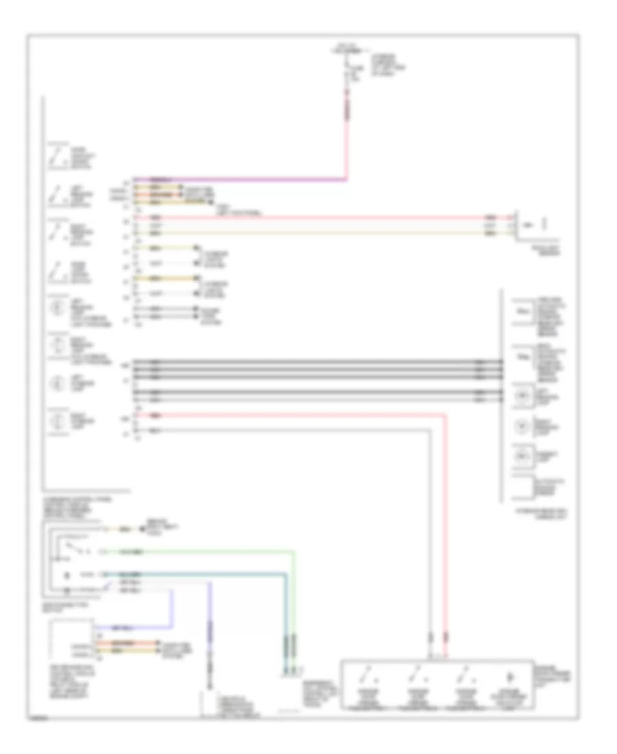
COMPUTER DATA LINES
Data Link Connector Wiring Diagram for Mercedes-Benz SLK350 2005
List of elements for Data Link Connector Wiring Diagram for Mercedes-Benz SLK350 2005:
- C13
- C19
- C20
- Can-b h
- Can-b l
- Central gateway control module (back side of left underdash panel)
- Computer data lines system (high/low bus circuit)
- Datalink connector (at left footwell)
- Driver-side sam control module with fuse & relay module (left rear of engine compt)
- Eis (ezs) control module (left side of dash)
- Exterior lamp switch
- Front prefuse box (on right rear of engine compt)
- Fuse 200a
- Fuse 5a
- Gnd
- Hot at all times
- Me-sfi (me) control module (on center of engine)
- Pnk/red
- Rear sam control unit with fuse & relay module (front of trunk)
- Red
- W29/10 (left kick panel)
- W9 (left front of engine compt)
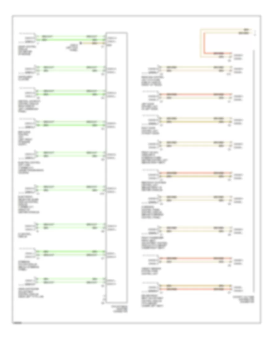
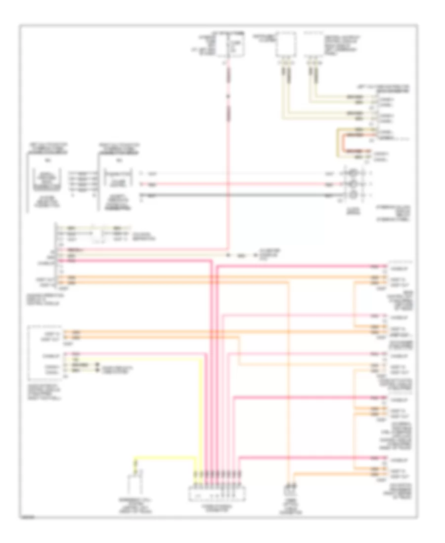
High/Low Bus Wiring Diagram (1 of 2) for Mercedes-Benz SLK350 2005
List of elements for High/Low Bus Wiring Diagram (1 of 2) for Mercedes-Benz SLK350 2005:
- C10
- Can databus adapter connector
- Can-b h
- Can-b l
- Can-c h
- Can-c l
- Central gateway control module (back side of left underdash panel)
- Cockpit voltage distributor connector
- Di control module
- Driver front seat adjustment control module with memory (under left seat)
- Electric control unit (vgs) (7 speed a/t) (inside transmission housing)
- Electronic selector lever module control module (7 speed a/t) (front of center console)
- Esp & bas control unit (left front of engine compt)
- Front hs (sih), airscarf & steering wheel heater control unit (behind right seat)
- Front passenger front seat adjustment control module with memory (under right seat)
- Gnd
- Headlamp range adjustment control module (near left "a" pillar)
- Instrument cluster
- Left door control unit (in left door)
- Me-sfi control module (on center of engine)
- Overhead control panel control module (behind overhead control panel)
- Rear sam control unit with fuse & relay module (front of trunk)
- Restraint systems control unit (behind front of center console)
- Right door control unit (in right door)
- Steering column module (below steering wheel)
- W29/10 (left kick panel)
- Weight sensing system (wss) control unit
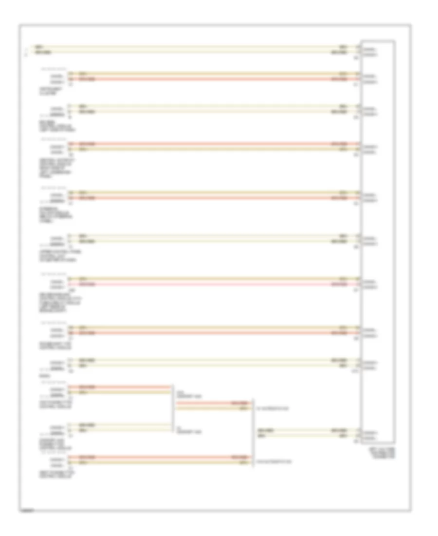
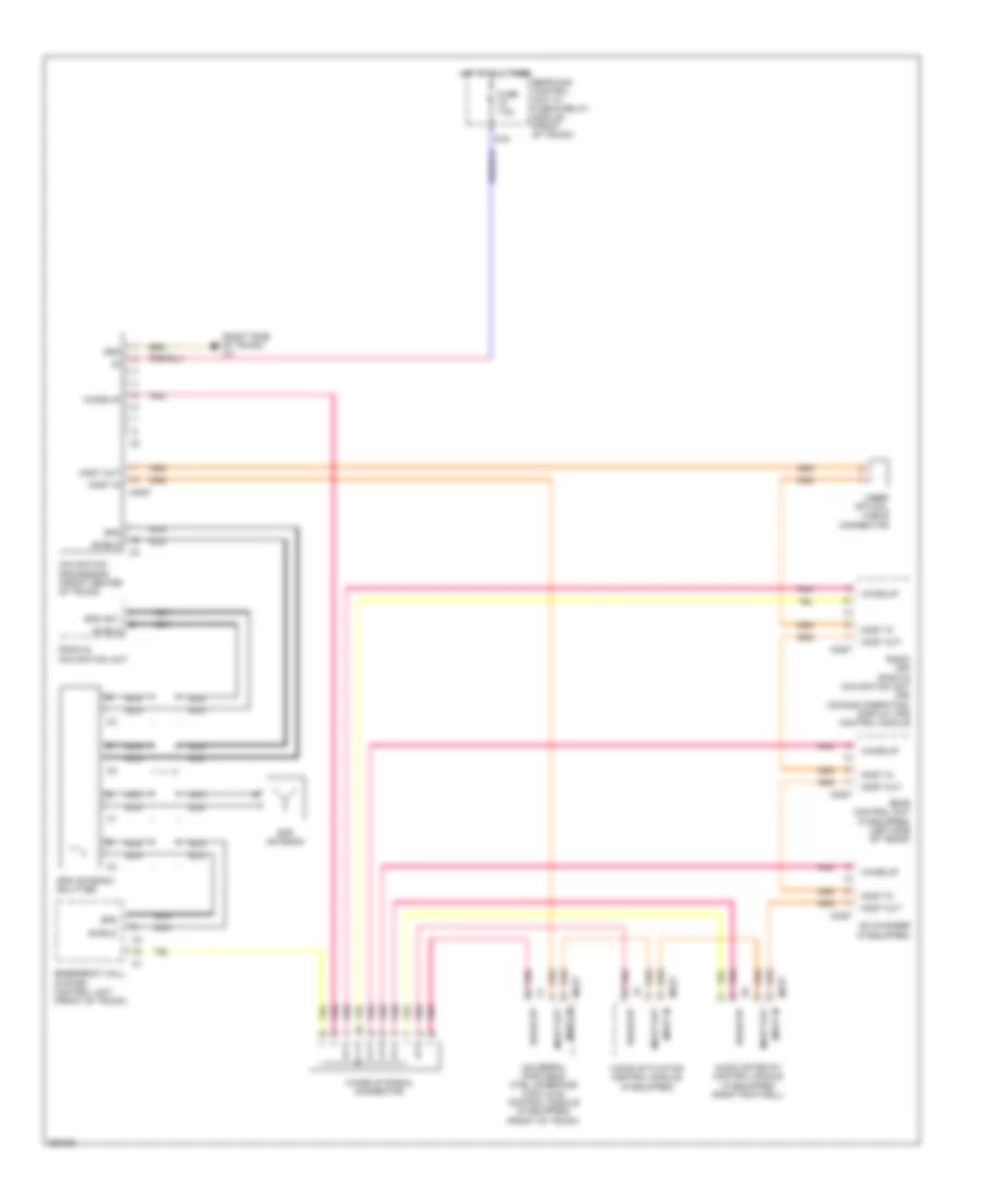
High/Low Bus Wiring Diagram (2 of 2) for Mercedes-Benz SLK350 2005
List of elements for High/Low Bus Wiring Diagram (2 of 2) for Mercedes-Benz SLK350 2005:
- Aac pushbutton control module
- C10
- C20
- Can-b h
- Can-b l
- Central gateway control module (back side of left underdash panel)
- Comfort aac pushbutton control module
- Driver-side sam control module with fuse & relay module (left rear of engine compt)
- Eis (ezs) control module (left side of dash)
- Heat pushbutton control module
- Instrument cluster
- Left voltage distributor connector
- Power soft top control module
- Radio
- Steering column module (below steering wheel)
- Upper control panel control unit (in center of dash)
- W/ automatic a/c
- W/ comfort aac
- W/o automatic a/c
- W/o comfort aac
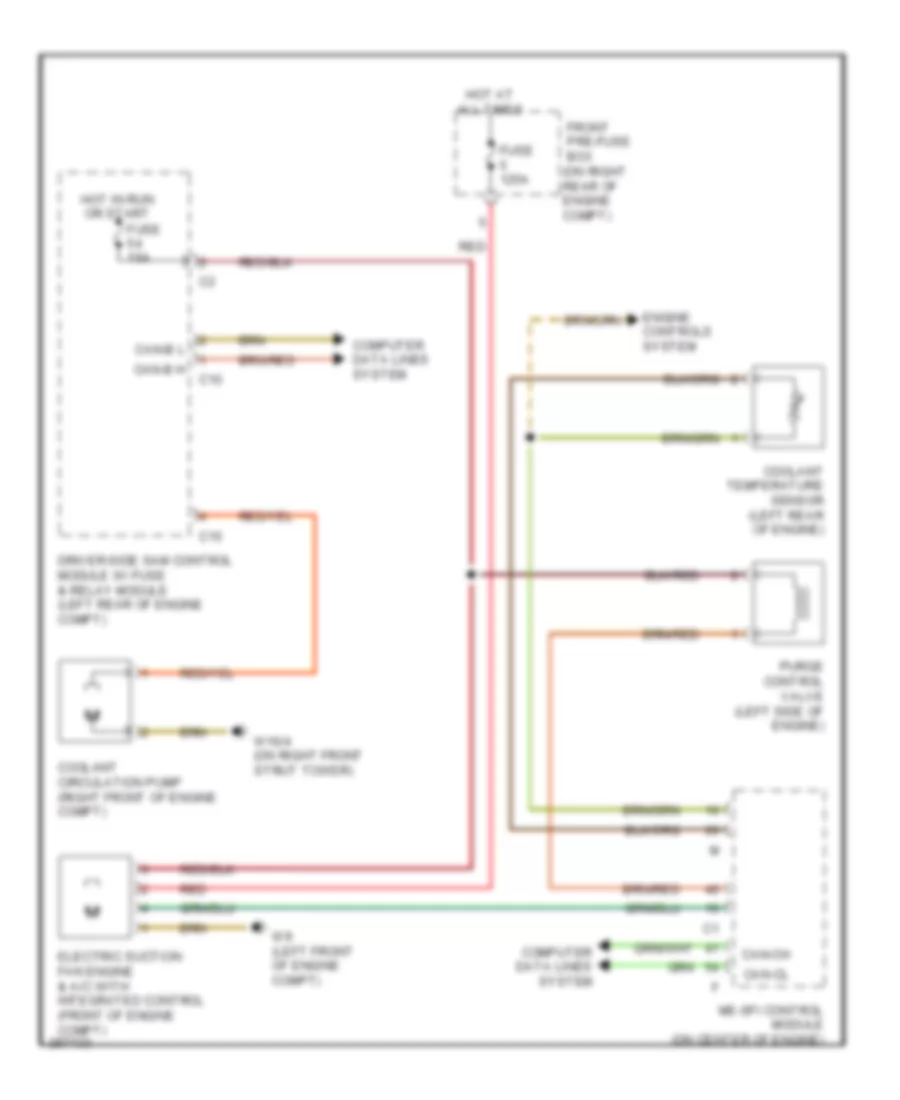
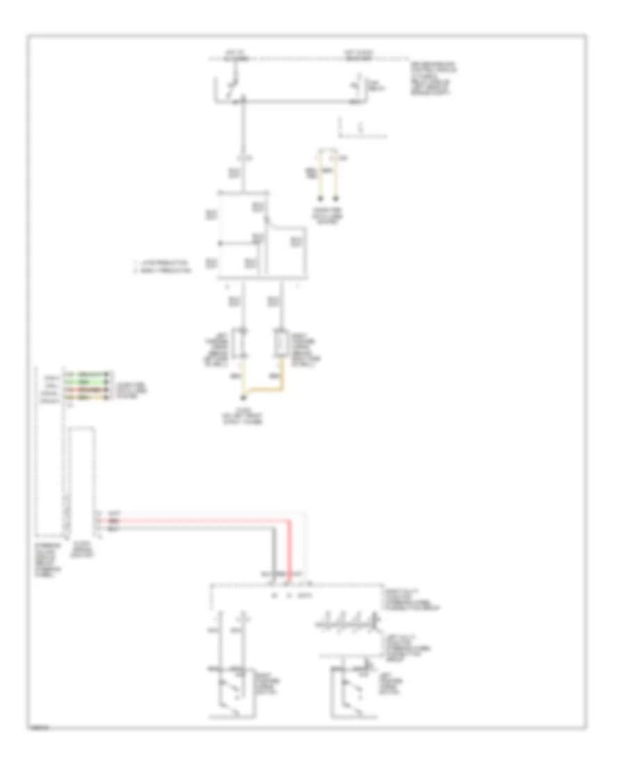
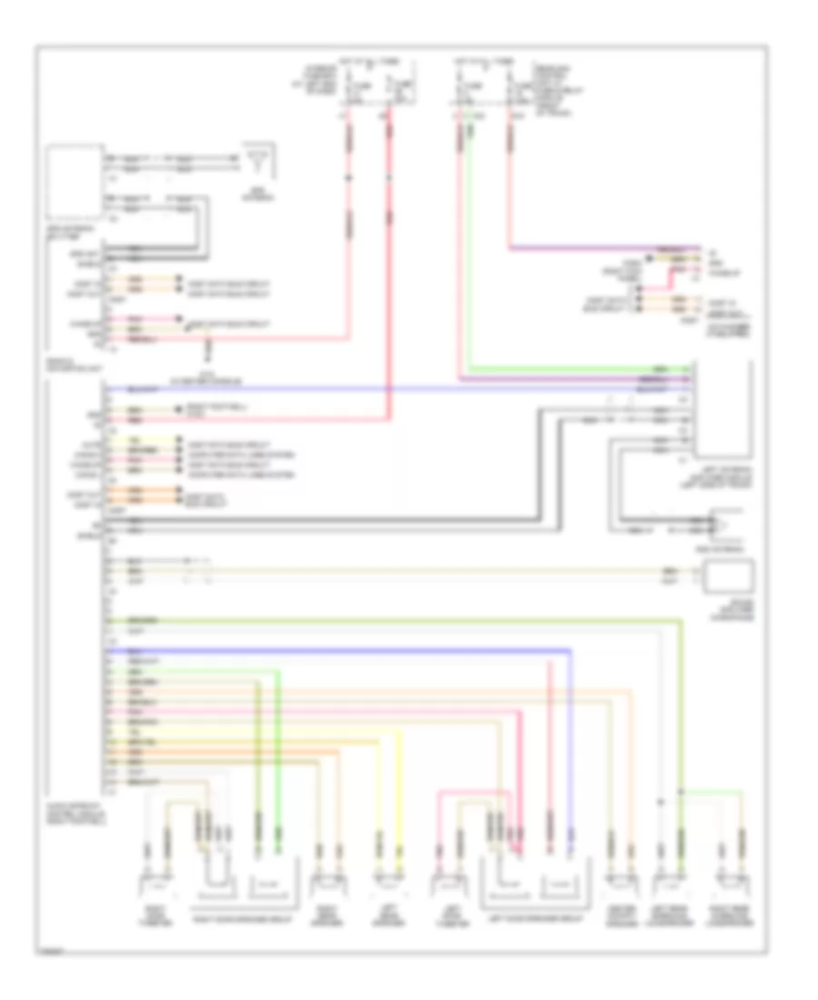
COOLING FAN
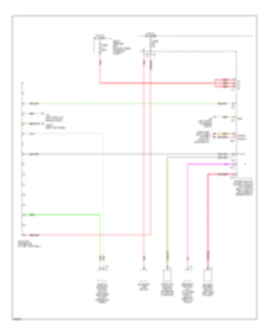
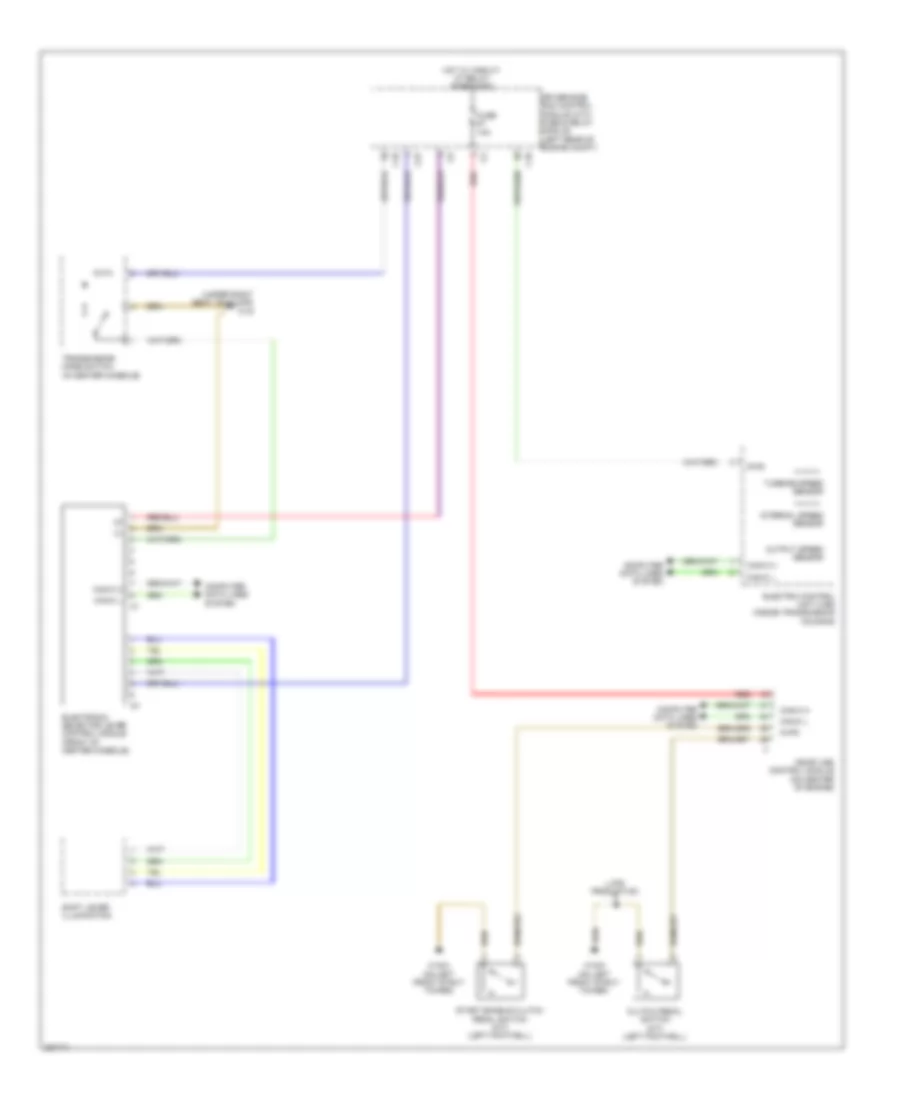
Cooling Fan Wiring Diagram for Mercedes-Benz SLK350 2005
List of elements for Cooling Fan Wiring Diagram for Mercedes-Benz SLK350 2005:
- me-sfi control module (on center of engine)
- (on right rear of engine compt)
- C10
- C15
- Can-b h
- Can-b l
- Can-ch
- Can-cl
- Computer data lines system
- Coolant circulation pump (right front of engine compt)
- Coolant temperature sensor (left rear of engine)
- Driver-side sam control module w/ fuse & relay module (left rear of engine compt)
- Electric suction fan engine & a/c with integrated control (front of engine compt)
- Engine controls system
- Front pre-fuse box
- Fuse 125a
- Fuse 15a
- Hot at all times
- Hot in run or start
- Purge control valve (left side of engine)
- Red
- W16/4 (on right front strut tower)
- W9 (left front of engine compt)
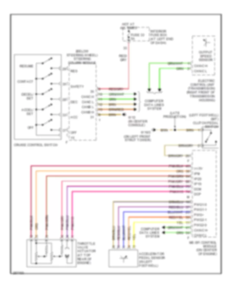
CRUISE CONTROL
Cruise Control Wiring Diagram for Mercedes-Benz SLK350 2005
List of elements for Cruise Control Wiring Diagram for Mercedes-Benz SLK350 2005:
- (+) 5v
- (below steering wheel) steering column module
- (late production)
- (left footwell) (m/t) clutch pedal switch
- (on left front strut tower)
- Acc
- Accel/ set
- Accelerator pedal sensor (in left footwell)
- Can-c h
- Can-c l
- Canb h
- Canb l
- Canc h
- Canc l
- Computer data lines system
- Contact
- Cruise control switch
- Dcm
- Dcp
- Dec
- Decel/ set
- Electric control unit (transmission) (right front of transmission housing)
- Fuse 33 5a
- Hot at all times
- Interior fuse box (at left end of dash)
- Ip1s
- Ip2s
- Ipm
- Me-sfi control module (on center of engine)
- Off
- Output speed sensor
- Pwg+
- Pwg1-0
- Pwg1-1
- Pwg2-0
- Pwg2-1
- Res
- Resume
- Safety
- Throttle valve actuator (at top rear of engine)
- W12 (in center console)
- W16/3
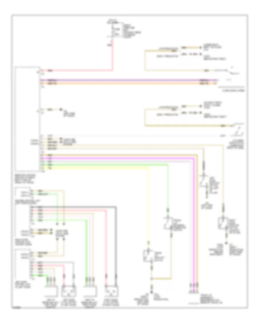
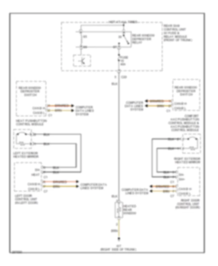
DEFOGGERS
Defoggers Wiring Diagram for Mercedes-Benz SLK350 2005
List of elements for Defoggers Wiring Diagram for Mercedes-Benz SLK350 2005:
- C20
- Can b h
- Can b l
- Can-b h
- Can-b l
- Comfort aac pushbutton control module & aac pushbutton control module
- Computer data lines system
- Fuse 40a
- Heat
- Heat pushbutton control module
- Heated rear window
- Hot at all times
- Left door control unit (in left door)
- Left exterior heated mirror
- Rear sam control unit w/ fuse & relay module (front of trunk)
- Rear window defroster relay
- Rear window defroster switch
- Right door control unit (in right door)
- Right exterior heated mirror
- Sh+
- Sh-
- W7 (right side of trunk)
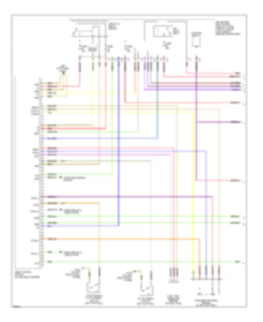
ENGINE PERFORMANCE
3.5L
3.5L, Engine Performance Wiring Diagram (1 of 4) for Mercedes-Benz SLK350 2005
List of elements for 3.5L, Engine Performance Wiring Diagram (1 of 4) for Mercedes-Benz SLK350 2005:
- (left kick panel) w29/10
- Aav
- Accelerator pedal sensor (in left footwell)
- Air pump relay
- C13
- C17
- C18
- Can-c h
- Can-c l
- Circuit 87 relay, engine
- Clutch pedal switch (left footwell)
- Computer data lines system
- Driver side sam control module w/ fuse & relay module (left rear of engine compartment)
- Dst
- Ekp
- Fuel tank pressure sensor (on fuel tank)
- Fuse 15a
- Fuse 40a
- Fuse 5a
- Gnd
- Kup2
- Lues
- M/t
- Mdr
- Me-sfi control module (on center of engine)
- Pwg+
- Pwg1-0
- Pwg1-1
- Pwg2-0
- Pwg2-1
- Red
- Reg
- Sens1
- Solid state
- Start enable clutch pedal switch (left footwell)
- Starter relay
- Starting/charging system
- Str
- Tna
- Uref1
- W16/3 (on left front strut tower)
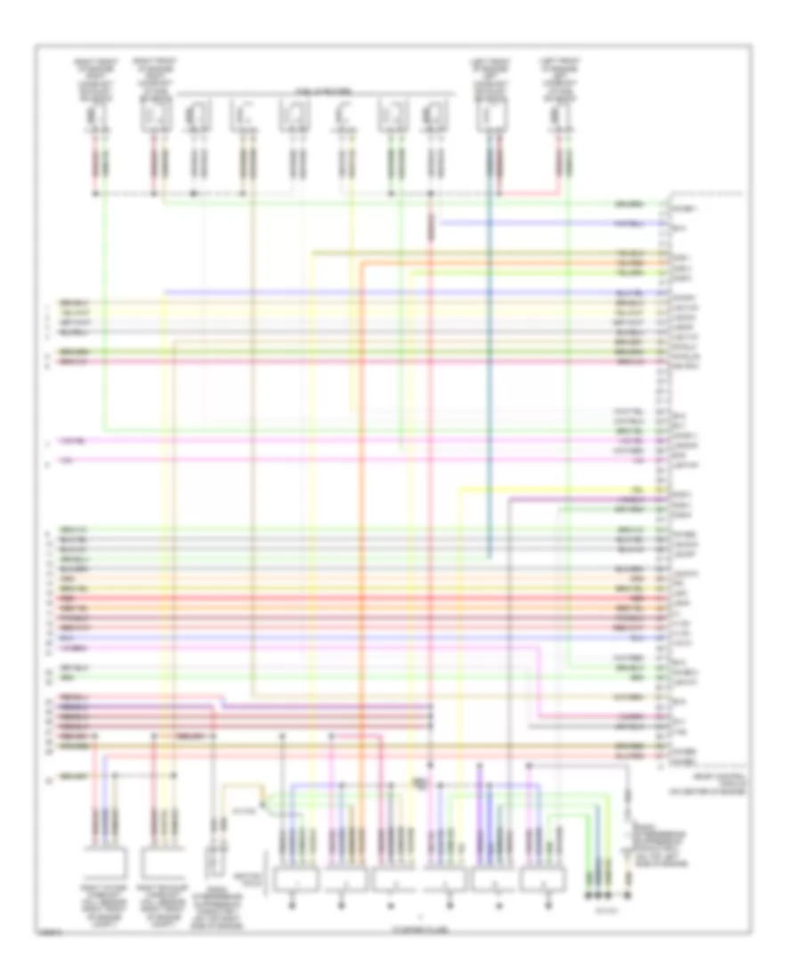
3.5L, Engine Performance Wiring Diagram (2 of 4) for Mercedes-Benz SLK350 2005
List of elements for 3.5L, Engine Performance Wiring Diagram (2 of 4) for Mercedes-Benz SLK350 2005:
- (front of trunk) rear sam control unit with fuse & relay module
- (in fuel tank) fuel level sensor
- (left front of engine compt) w9
- Activated charcoal filter shutoff valve (under rear of vehicle)
- Air pump
- Air pump switchover valve (right front of engine)
- Can-b h
- Can-b l
- Computer data lines system
- Engine & a/c electric suction fan with integrated control (front of engine compt)
- Front prefuse box (on right rear of engine compt)
- Fuel pump
- Fuel pump relay
- Fuse 125a
- Fuse 200a
- Fuse 20a
- Generator
- Hot at all times
- Hot film mass air flow sensor (rear of engine compt)
- Left knock sensor 2 (in valley of engine block)
- Nca
- Purge control valve (left side of engine)
- Red
- Right knock sensor 1 (in valley of engine block)
- Three-disk thermostat valve (right front of engine)
- Throttle valve actuator (at top rear of engine)
- W11w2
- W32/2 (behind right seat)
- W6 (left side of trunk)
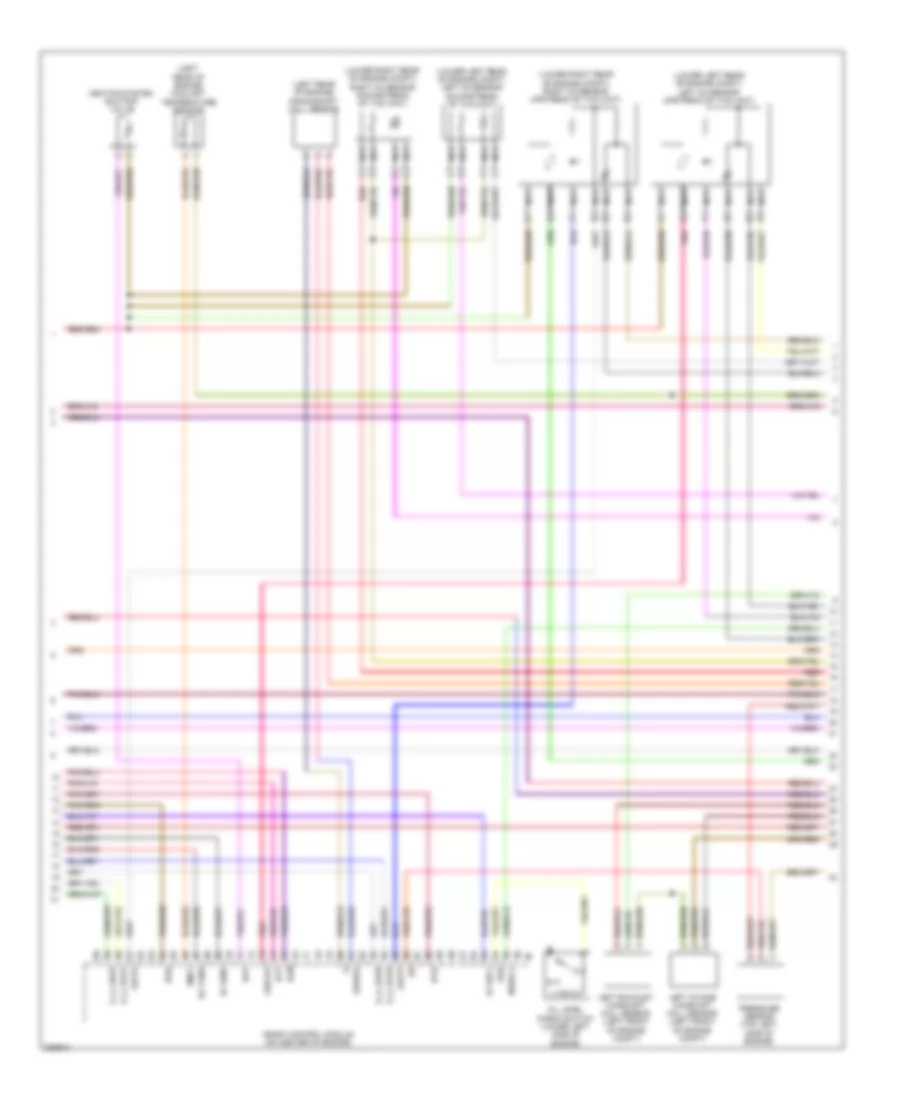
3.5L, Engine Performance Wiring Diagram (3 of 4) for Mercedes-Benz SLK350 2005
List of elements for 3.5L, Engine Performance Wiring Diagram (3 of 4) for Mercedes-Benz SLK350 2005:
- (-)
- (left rear of engine) coolant temperature sensor
- (left rear of engine) crankshaft hall sensor
- (lower left rear of engine compt) left o2 sensor downstream of twc (kat)
- (lower left rear of engine compt) left o2 sensor upstream of twc (kat)
- (lower right rear of engine compt) right o2 sensor downstream of twc (kat)
- (lower right rear of engine compt) right o2 sensor upstream of twc (kat)
- Dcm
- Dcp
- Ea tans
- Ef hfm1
- Ef ref1
- E_a_ks1a
- E_a_ks1b
- E_a_ks2a
- E_a_ks2b
- Hav
- Heating system shutoff valve
- Ip1s
- Ip2s
- Kwdga
- Left exhaust camshaft hall sensor (left front of engine compt)
- Left intake camshaft hall sensor (left front of engine compt)
- Lshvk2
- Lsu1a
- Lsu1p
- Me-sfi control module (on center of engine)
- Nca
- Nwsa 2
- Oil level check switch (lower left side of engine)
- Oss
- Pnk
- Pressure sensor (top left side of engine)
- Red
- Tmot
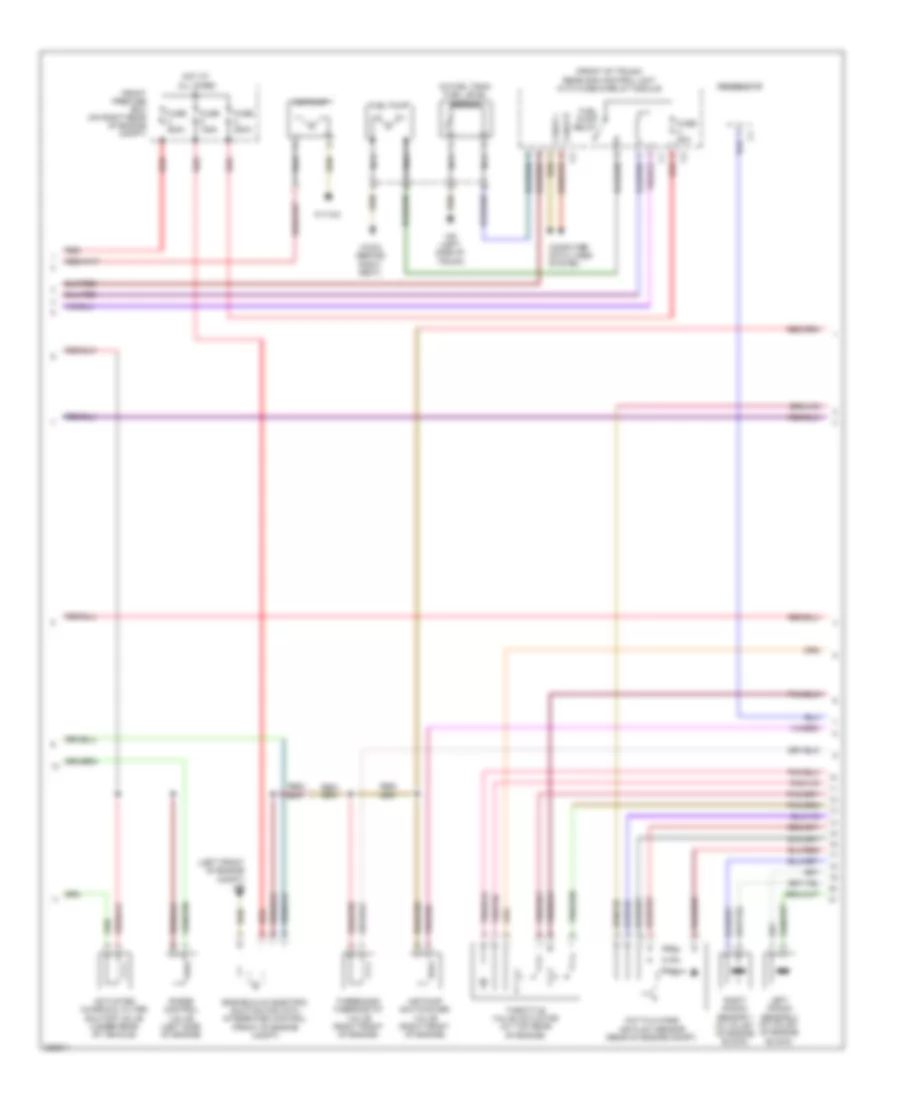
3.5L, Engine Performance Wiring Diagram (4 of 4) for Mercedes-Benz SLK350 2005
List of elements for 3.5L, Engine Performance Wiring Diagram (4 of 4) for Mercedes-Benz SLK350 2005:
- (+)
- (+) sv
- (left front of engine) left camshaft exhaust solenoid
- (left front of engine) left camshaft intake solenoid
- (right front of engine) right camshaft exhaust solenoid
- (right front of engine) right camshaft intake solenoid
- Ev1
- Ev2
- Ev3
- Ev4
- Ev5
- Ev6
- Fuel injectors
- Ignition coils
- Ipm
- Lin c1
- Ls2hk
- Lsh1hk
- Lsh2hk
- Lshk
- Lshvk1
- Lsik
- Lsu1un
- Lsu1vm
- Lsu2ia
- Lsu2ip
- Lsu2un
- Lsu2vm
- Me-sfi control module (on center of engine)
- Mr hfm1
- Nwae2
- Nwga1
- Nwge1
- Nwge2
- Nwg_m
- Nwg_m2
- Nwsa 1
- Nwse 1
- Nwse 2
- Radio interference suppression capacitor 1 (on top right side of engine)
- Radio interference suppression capacitor 2 (on top left side of engine)
- Red
- Right exhaust camshaft hall sensor (right front of engine compt)
- Right intake camshaft hall sensor (right front of engine compt)
- Slv
- Ths
- To spark plugs
- W11w1
- W11w2
- Zue 1
- Zue 2
- Zue 3
- Zue 4
- Zue 5
- Zue 6
EXTERIOR LIGHTS
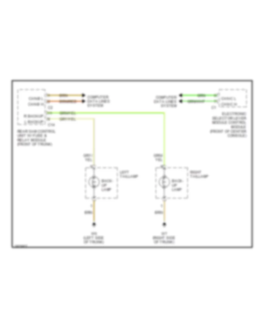
Backup Lamps Wiring Diagram for Mercedes-Benz SLK350 2005
List of elements for Backup Lamps Wiring Diagram for Mercedes-Benz SLK350 2005:
- Back- up lamp
- C14
- Can-b h
- Can-b l
- Can-c h
- Can-c l
- Computer data lines system
- Electronic selector lever module control module (front of center console)
- L backup
- Left taillamp
- R backup
- Rear sam control unit w/ fuse & relay module (front of trunk)
- Right taillamp
- W6 (left side of trunk)
- W7 (right side of trunk)
Exterior Lamps Wiring Diagram (1 of 2) for Mercedes-Benz SLK350 2005
List of elements for Exterior Lamps Wiring Diagram (1 of 2) for Mercedes-Benz SLK350 2005:
- Auto
- C13
- C19 red
- C20
- Can-b h
- Can-b l
- Can-c h
- Can-c l
- Computer data lines system
- Df vl a
- Df vr a
- Driver-side sam control module w/ fuse & relay module (left rear of engine compt)
- Esp & bas control unit (left front of engine compt)
- Exterior lamp switch
- Exterior lamps
- Fog lamp
- Fog lamp ind
- Fuse 5a
- Gnd
- Head
- Headlamp wash
- Headlights system
- Hot at all times
- Instrument cluster
- Left
- Left door control unit (in left door)
- Left exterior mirror
- Left front headlamp unit
- Left front side marker lamp
- Left turn ind
- Lf mark
- Lf park
- Lf turn
- Mirror adjust
- Mirror fold
- Mirror select
- Off
- Out
- Park
- Red
- Rf mark
- Rf park
- Rf turn
- Right
- Right door control unit (in right door)
- Right exterior mirror
- Right front headlamp unit
- Right front side marker lamp
- Right turn ind
- Sounder
- Standing/ parking lamp
- Turn
- Turn lamp
- Turn signal lamp
- W16/3 (on left front strut tower)
- W16/4 (on right front strut tower)
- W29/1 (left kick panel)
- W9 (left front of engine compt)
Exterior Lamps Wiring Diagram (2 of 2) for Mercedes-Benz SLK350 2005
List of elements for Exterior Lamps Wiring Diagram (2 of 2) for Mercedes-Benz SLK350 2005:
- (in center console) w12
- Back- up lamp
- C14
- C21
- C24
- Can-b h
- Can-b l
- Center high mount stop lamp
- Chmsl
- Combination switch
- Computer data lines system
- Front prefuse box (on right rear of engine compt)
- Fuse 200a
- Fuse 5a
- Hazard switch
- Hot at all times
- Interior fuse box (at left end of dash)
- L backup
- L fog
- L license
- L park
- L turn
- Left & right turn signal switch
- Left license plate lamp
- Left taillamp unit
- Left trunk lamp
- Lr mark
- Overhead control panel control module (behind overhead control panel)
- R backup
- R fog
- R license
- R park
- R turn
- Rain/light sensor
- Rear fog lamp
- Rear sam control unit w/ fuse & relay module (front of trunk)
- Rear side marker lamp
- Red
- Right license plate lamp
- Right taillamp unit
- Rr mark
- Steering column module (below steering wheel)
- Tail/ park/ stop lamp
- Turn signal lamp
- Upper control panel control unit (in center of dash)
- W6 (left side of trunk)
- W7 (right side of trunk)
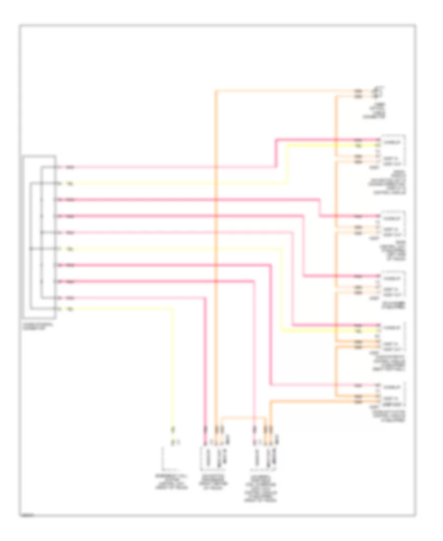
GROUND DISTRIBUTION
Ground Distribution Wiring Diagram for Mercedes-Benz SLK350 2005
List of elements for Ground Distribution Wiring Diagram for Mercedes-Benz SLK350 2005:
- (in center console)
- Ac recirculation unit, heat push-button control module, right door control module, cd changer, right front footwell lamp, c-aac (k-kla) multifunction sensor (if equipped) & glove compartment cl (zv) motor
- Driver front seat adjustment control module w/ memory, left front backrest heated cushion, left front seat heated cushion & left airscarf heating element (if equipped),
- Driver-side sam control module
- Electric steering lock control module, steering column module, radio, left front footwell lamp, interior socket, upper control panel control module, cigar lighter, instrument cluster, comm & operating , display & control module, radio & navigation unit & eis (ezs) control unit
- Electric suction fan engine & ac
- Electronic selector lever module control module, parking brake indicator switch, mb-info & breakdown assistance button group, ata (edw) hood switch, alarm signal siren, fuel pump, backup lamp switch, glove box switch, center console compartment switch, transmission mode switch, electric control unit, center console compartment cl (zv) motor & frequency switch over control module & sos push button switch
- Emergency call system control unit, voice control system control module, right door contact switch, navigation processor, vario-roof locked limit switch, right tail lamp, heated rear window & tubular frame open limit switch
- Esp & bas control module, data link connector,
- Headlamp range adjustment control module, left front side marker lamp, left fog lamp, driver side sam control module w/ fuse & relay module, control module box blower motor, right fanfare horn, start enable clutch pedal switch, clutch pedal switch, left fanfare horn, brake fluid indicator switch, left front headlamp unit & sleeve connector
- Left door control module, center gateway control module, stowage compartment illumination between backrests, armrest stowage compartment illumination, overhead control panel control module, exterior lamp switch, sos push button switch & electric control unit (vgs)
- Me-sfi (me) control module & can databus adapter connector data link connector
- Restraint systems control module, passenger-side frontal acceleration sensor, driver-side frontal acceleration sensor, driver-side seat belt buckle restraint systems switch, left side air bag sensor, passenger-side seat belt buckle restraint systems switch, passenger seat occupied & child seat recognition sensor, weight sensing system (wss) control unit & right side air bag sensor,
- Right front side marker lamp (usa), right fog lamp, windshield washer fluid pump, hcs pump (if equipped), coolant circulation pump (w/comfort aac), left heated windshield washer nozzle, right heated windshield washer nozzle & right front headlamp unit
- Sdar control unit, power soft top control module, rear sam control module, left tail lamp, left trunk lamp, left door contact switch, trunk partition closed limit switch, vario-roof open/lowered limit switch, tubular frame locked limit switch, soft top mechanism hydraulic unit, fuel level sensor, left license plate lamp, right license plate lamp, center high-mounted stop lamp, trunk lid external operation switch & rotary tumbler/trunk lid microswitch
- Sh (sih),airscarf & steering wheel heater control unit, front passenger front seat adjustment control module w/ memory, right front backrest heated cushion, right front seat heated cushion & right airscarf heating element (if equipped)
- W/ fuse & relay module &
- W/ integrated control
- W12
- W16/3 (on left front strut tower)
- W16/4 (on right front strut tower)
- W18 (under left seat, on floor)
- W19 (under right seat, on floor)
- W26 (lower center of dash)
- W29/1 (left kick panel)
- W29/10 (left kick panel)
- W29/2 (right kick panel)
- W32/2 (behind right seat)
- W6 (left side of trunk)
- W7 (right side of trunk)
- W9 (left front of engine compt)
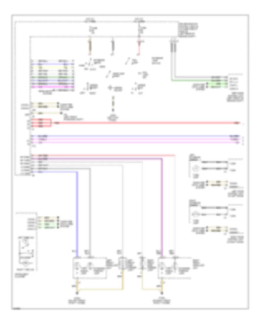
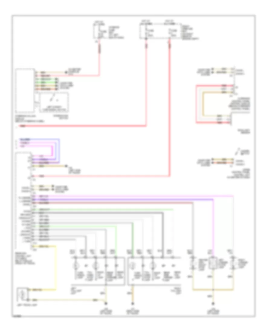
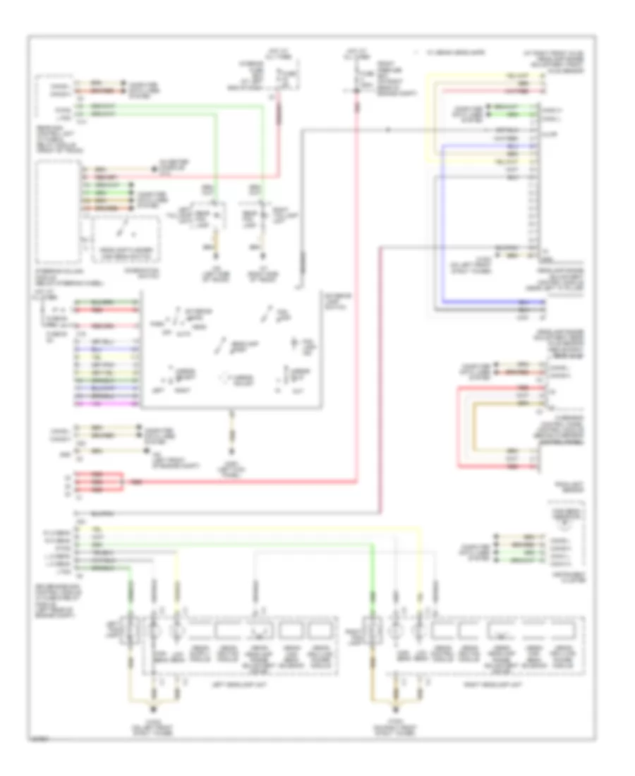
HEADLIGHTS
Headlights Wiring Diagram for Mercedes-Benz SLK350 2005
List of elements for Headlights Wiring Diagram for Mercedes-Benz SLK350 2005:
- (at right front axle) headlamp range adjustment front axle sensor
- (in center console) w12
- Alwr
- Auto
- C14
- C19
- C20
- C24
- Can-b h
- Can-b l
- Can-c h
- Can-c l
- Combination switch
- Computer data lines system
- Driver-side sam control module w/ fuse & relay module (left rear of engine compt)
- Exterior lamp switch
- Exterior lamps
- Fog lamp
- Fog lamp ind
- Front prefuse box (on right rear of engine compt)
- Fuse 200a
- Fuse 5a
- Fuse 62 5a
- Fuse 63 5a
- Gnd
- Head
- Headlamp flasher/ high beam switch
- Headlamp range adjustment control module (near left "a" pillar)
- Headlamp range adjustment rear axle sensor (above right rear axle)
- Headlamp wash
- High beam
- High beam indicator
- Hot at all times
- Instrument cluster
- Interior fuse box (at left end of dash)
- L fog
- L hi beam
- L lo beam
- Left
- Left fog lamp
- Left headlamp unit
- Left taillamp unit
- Low beam
- Mirror adjust
- Mirror fold
- Mirror select
- Off
- Out
- Overhead control panel control module (behind overhead control panel)
- Park
- R fog
- R hi beam
- R lo beam
- Rain/light sensor
- Rear fog lamp
- Rear sam control unit w/ fuse & relay module (front of trunk)
- Red
- Right
- Right fog lamp
- Right headlamp unit
- Right taillamp unit
- Steering column module (below steering wheel)
- W/ xenon headlamps
- W16/3 (on left front strut tower)
- W16/4 (on right front strut tower)
- W29/1 (left kick panel)
- W6 (left side of trunk)
- W7 (right side of trunk)
- W9 (left front of engine compt)
- Xenon control module
- Xenon headlamp range adjustment motor
- Xenon high beam solenoid
- Xenon hra (lwr) power module
- Xenon ignition module
HORN
Horn Wiring Diagram for Mercedes-Benz SLK350 2005
List of elements for Horn Wiring Diagram for Mercedes-Benz SLK350 2005:
- C20
- Can b h
- Can b l
- Can h
- Can l
- Clock spring contact
- Computer data lines system
- Data
- Driver-side sam control module w/ fuse & relay module (left rear of engine compt)
- Early production
- Fan relay
- Hot at all times
- Hot in run or start
- Late production
- Left fanfare horns (behind left side of grill)
- Left fanfare horns switch
- Left multi- function steering wheel pushbutton group
- Nca
- Red
- Right fanfare horns (behind right side of grill)
- Right fanfare horns switch
- Right multi- function steering wheel pushbutton group
- Steering column module (below steering wheel)
- W16/3 (on left front strut tower)
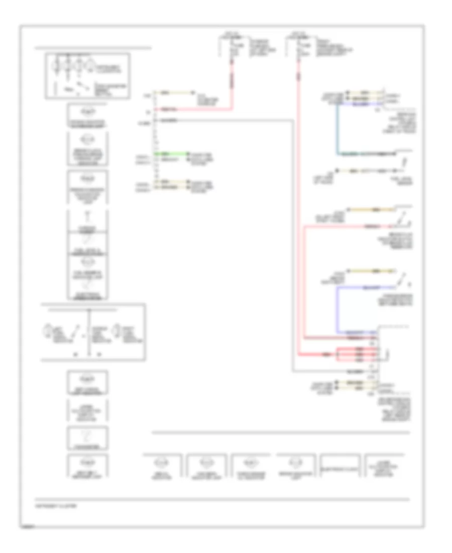
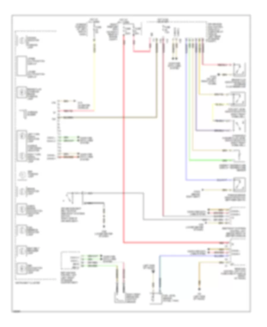
INSTRUMENT CLUSTER
Instrument Cluster Wiring Diagram for Mercedes-Benz SLK350 2005
List of elements for Instrument Cluster Wiring Diagram for Mercedes-Benz SLK350 2005:
- "check engine" mil indicator
- 15 ges
- 31e
- Abs mil indicator
- Air bag indicator & warning lamp
- Audible turn signal indicator
- Brake fluid & parking brake warning lamp indicator
- Brake fluid indicator switch (on brake fluid reservoir)
- Brake indicator light
- C19
- C20
- Can-b h
- Can-b l
- Can-c h
- Can-c l
- Computer data lines system
- Driver-side sam control module w/fuse & relay module (left rear of engine compt)
- Electronic clock
- Electronic speedometer
- Engine diagnosis malfunction indicator lamp
- Esp waring lamp indicator
- Front prefuse box (on right rear of engine compt)
- Fuel level & reserve gauge
- Fuel level sensor
- Fuel reserve indicator lamp
- Fuse 200a
- Fuse 5a
- High beam indicator lamp
- Hot at all times
- Instrument cluster
- Instrument illumination
- Interior fuse box (at left end of dash)
- Left turn signal indicator
- Lower multifunction display indicator
- Nca
- Parking brake indicator switch (between seats)
- Rear sam control unit w/fuse & relay module (front of trunk)
- Red
- Right turn signal indicator
- Seat belt reminder lamp
- Tachometer
- Trip odometer reset button
- Upper multifunction display indicator
- W12 (in center console)
- W16/3 (on left front strut tower)
- W32/2 (behind rigth seat)
- W6 (left side of trunk)
- Warning buzzer
Overhead Console Wiring Diagram for Mercedes-Benz SLK350 2005
List of elements for Overhead Console Wiring Diagram for Mercedes-Benz SLK350 2005:
- (behind right seat) w32/2
- 15r
- Ambient lamp
- Automatic dimming mirror
- Back automatic dimming interior rearview mirror sensor
- Can-b h
- Can-b l
- Computer data lines system
- Dome lamp on/off switch
- Door contact on/off switch
- Driver-side sam control module w/fuse & relay module (left rear of engine compt)
- Emergency call system control unit (front of trunk)
- Forward automatic dimming interior rearview mirror sensor
- Fuse 15a
- Garage door opener indicator lamp
- Garage door opener pushbutton 1
- Garage door opener pushbutton 2
- Garage door opener pushbutton 3
- Garage door opener transmitter unit
- Hot at all times
- Interior fuse box (at left end of dash)
- Interior lights system
- Interior rearview mirror unit
- Left interior lamp
- Left reading lamp
- Left reading lamp (w/o interior light package)
- Left reading lamp switch
- Mb-info & breakdown assistance button group
- Nca
- Overhead control panel control module (behind overhead control panel)
- Power tops system
- Rain/light sensor
- Red
- Right interior lamp
- Right reading lamp
- Right reading lamp (w/o interior light package)
- Right reading lamp switch
- Sos pushbutton switch
- W29/1 (left kick panel)
INTERIOR LIGHTS
Courtesy Lamps Wiring Diagram for Mercedes-Benz SLK350 2005
List of elements for Courtesy Lamps Wiring Diagram for Mercedes-Benz SLK350 2005:
- (left side of trunk) w6
- C-acc (k-kla) multifunction sensor
- C13
- C20
- C21
- C23
- C24
- Can-b h
- Can-b l
- Computer data lines system
- Dome
- Dome contact on & off
- Door contact on & off
- Driver-side sam control module w/ fuse & relay module (left rear of engine compt)
- Front
- Fuse 200a
- Fuse 5a
- Glove compartment illumination with switch (early production) glove compartment lamp (late production)
- Gnd
- Hot at all times
- Hot w/ circuit 15r relay energized
- Left door contact switch
- Left door control unit (in left door)
- Left door entrance & exit lamp
- Left front vanity mirror illumination
- Left front vanity mirror illumination switch
- Left reading
- Left trunk lamp
- Lf door ajar
- Overhead control panel control module (behind overhead control panel)
- Prefuse box (on right rear of engine compt)
- Rear sam control unit w/ fuse & relay module (front of trunk)
- Red
- Rf door ajar
- Right door contact switch
- Right door control unit (in right door)
- Right door entrance & exit lamp
- Right front vanity mirror illumination
- Right front vanity mirror illumination switch
- Right reading
- Trunk lid emergency release switch
- Trunk lid external operation switch
- Trunk lid rotary tumbler microswitch (rear center of trunk lid)
- W/o cd changer
- W29/1 (left kick panel)
- W6 (left side of trunk)
- W7 (right side of trunk)
- W9 (left front of engine compt)
Instrument Illumination Wiring Diagram for Mercedes-Benz SLK350 2005
List of elements for Instrument Illumination Wiring Diagram for Mercedes-Benz SLK350 2005:
- 58d
- Auto
- C10
- C11
- C19
- C20
- C22
- C25
- Can-b h
- Can-b l
- Can-c h
- Can-c l
- Cigar lighter (w/ ashtray illumination)
- Computer data lines system
- Driver power window switch group
- Driver-side sam control module w/ fuse & relay module (left rear of engine compt)
- Emergency call system control unit (front of trunk)
- Exterior lamp switch
- Exterior lamps
- Fog lamp
- Fog lamp ind
- Front passenger power window switch
- Front prefuse box (on right rear of engine compt)
- Fuse 200a
- Fuse 5a
- Gnd
- Head
- Headlamp wash
- Headlights system
- Hot at all times
- Illum
- Instrument cluster
- Instrument illumination
- Left
- Left door control unit (in left door)
- Left power window switch
- Mb-info & breakdown assistance button group
- Mirror adjust
- Mirror fold
- Mirror select
- Off
- Out
- Park
- Red
- Right
- Right door control unit (in right door)
- Right power window switch
- Sos push button switch
- Transmission mode switch (in center console)
- W12 (in center console)
- W29/1 (left kick panel)
- W32/2 (behind right seat)
- W9 (left front of engine compt)
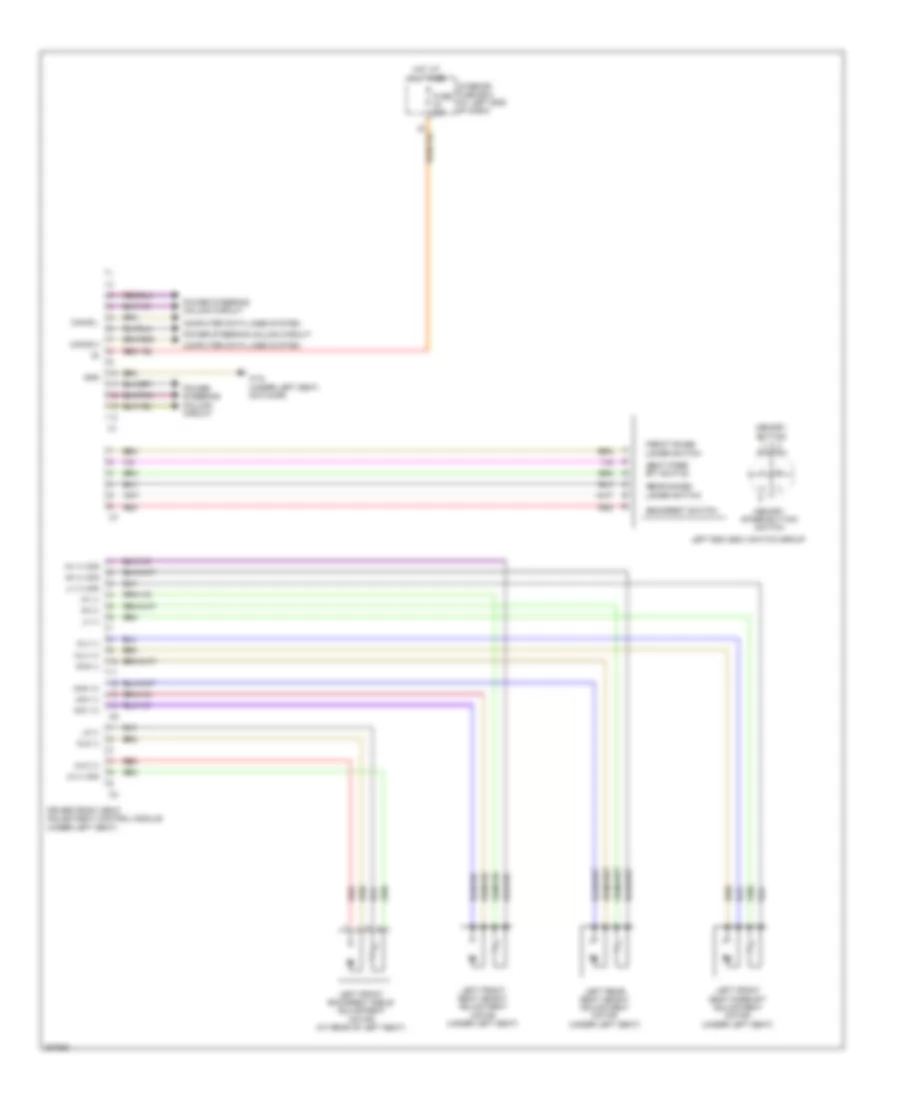
MEMORY SYSTEMS
Driver"s Memory Seat Wiring Diagram for Mercedes-Benz SLK350 2005
List of elements for Driver"s Memory Seat Wiring Diagram for Mercedes-Benz SLK350 2005:
- -backrest switch
- -front raise/ lower switch
- -rear raise/ lower switch
- -seat fore/ aft switch
- Can-b h
- Can-b l
- Computer data lines system
- Driver front seat adjustment control module (under left seat)
- Fuse 30a
- Gnd
- Hh (+) sig
- Hh (-)
- Hot at all times
- Hv (+) sig
- Hv (-)
- Interior fuse box (at left end of dash)
- Left esa (esv) switch group
- Left front backrest angle adjustment motor (at rear of left seat)
- Left front seat fore/aft adjustment motor (under left seat)
- Left front seat height adjustment motor (under left seat)
- Left rear seat height adjustment motor (under left seat)
- Lk (+) sig
- Lk (-)
- Lv (+) sig
- Lv (-)
- Memory button 1, 2, 3 switch
- Memory store button switch
- Mhh (+)
- Mhh (-)
- Mhv (+)
- Mhv (-)
- Mlk (+)
- Mlk (-)
- Mlv (+)
- Mlv (-)
- Power steering column circuit
- Red
- W18 (under left seat, on floor)
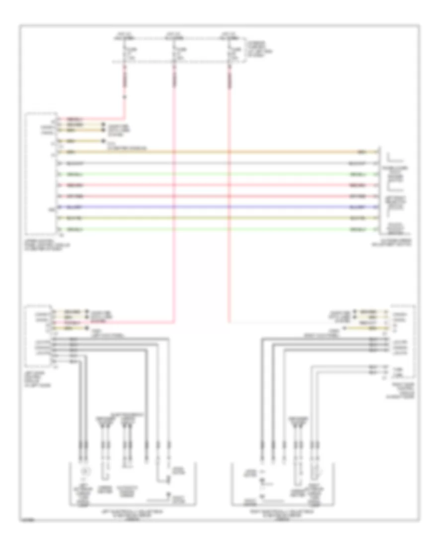
Memory Mirrors Wiring Diagram for Mercedes-Benz SLK350 2005
List of elements for Memory Mirrors Wiring Diagram for Mercedes-Benz SLK350 2005:
- (+)
- (-)
- 58d
- Automatic dimming mirror
- Can-b h
- Can-b l
- Common
- Computer data lines system
- Defogger system
- Electrochromic mirror circuit
- Fold
- Fold-in, fold-out switch
- Fuse 30a
- Fuse 7.5a
- Hot at all times
- In/out motor
- Interior fuse box (at left end of dash)
- L/r mtr
- Left door control module (in left door)
- Left electrically adjustable & heated exterior mirror
- Left exterior mirror turn signal lamp
- Left/right selection switch
- Mirror heater
- Outside mirror adjustment switch
- Raise/lower, in/out rocker switch
- Right door control module (in right door)
- Right electrically adjustable & heated exterior mirror
- Right exterior mirror turn signal lamp
- Turn
- U/d mtr
- Up/dn motor
- Upper control panel control module (in center of dash)
- W12 (in center console)
- W29/1 (left kick panel)
- W29/2 (right kick panel)
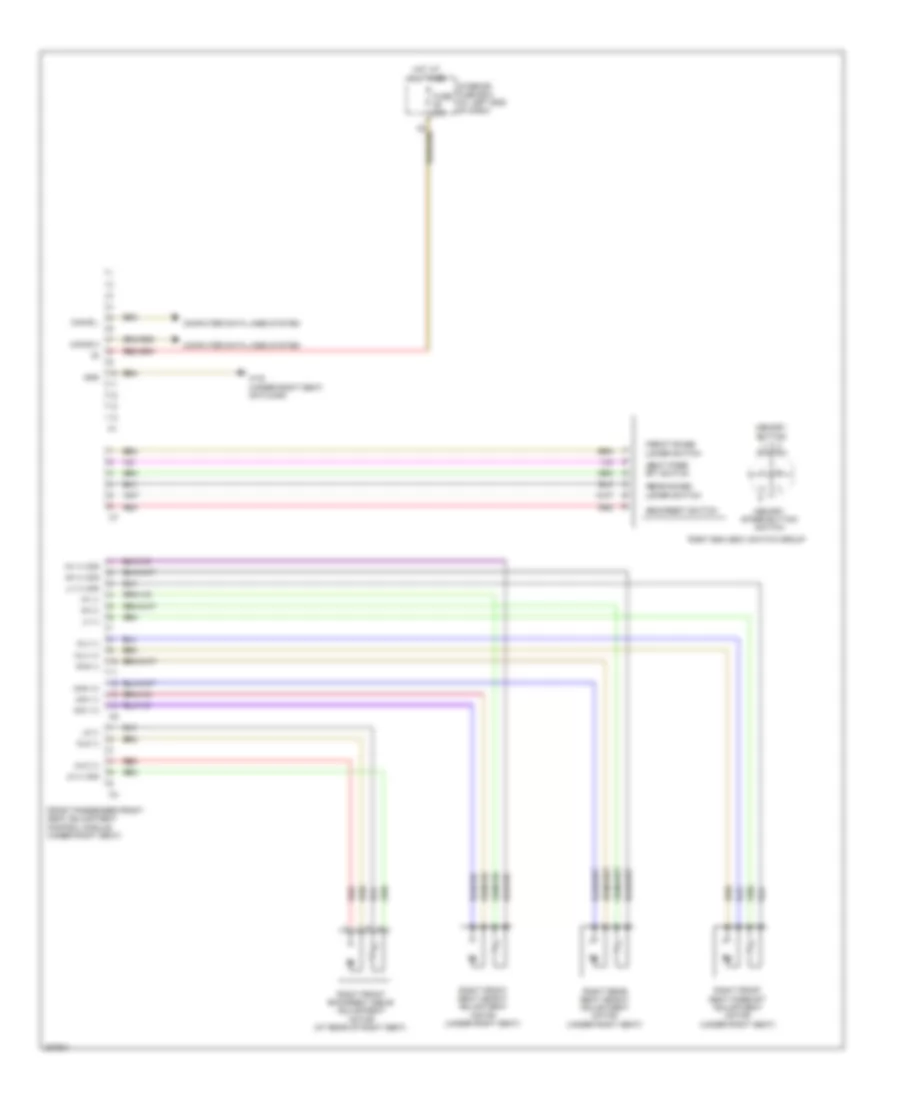
Passenger"s Memory Seat Wiring Diagram for Mercedes-Benz SLK350 2005
List of elements for Passenger"s Memory Seat Wiring Diagram for Mercedes-Benz SLK350 2005:
- -backrest switch
- -front raise/ lower switch
- -rear raise/ lower switch
- -seat fore/ aft switch
- Can-b h
- Can-b l
- Computer data lines system
- Front passenger front seat adjustment control module (under right seat)
- Fuse 30a
- Gnd
- Hh (+) sig
- Hh (-)
- Hot at all times
- Hv (+) sig
- Hv (-)
- Interior fuse box (at left end of dash)
- Lk (+) sig
- Lk (-)
- Lv (+) sig
- Lv (-)
- Memory button 1, 2, 3 switch
- Memory store button switch
- Mhh (+)
- Mhh (-)
- Mhv (+)
- Mhv (-)
- Mlk (+)
- Mlk (-)
- Mlv (+)
- Mlv (-)
- Red
- Right esa (esv) switch group
- Right front backrest angle adjustment motor (at rear of right seat)
- Right front seat fore/aft adjustment motor (under right seat)
- Right front seat height adjustment motor (under right seat)
- Right rear seat height adjustment motor (under right seat)
- W19 (under right seat, on floor)
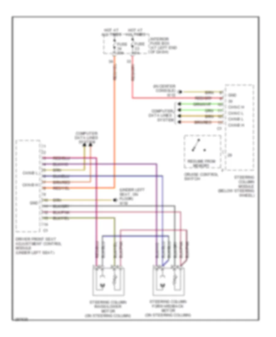
Steering Column Memory Wiring Diagram for Mercedes-Benz SLK350 2005
List of elements for Steering Column Memory Wiring Diagram for Mercedes-Benz SLK350 2005:
- (in center console) w12
- (under left seat, on floor) w18
- Can-b h
- Can-b l
- Can-c h
- Can-c l
- Computer
- Computer data lines system
- Cruise control switch
- Data lines
- Driver front seat adjustment control module (under left seat)
- Fuse 30a
- Fuse 5a
- Gnd
- Hot at all times
- Interior fuse box (at left end of dash)
- Resume from memory
- Steering column forward/back motor (on steering column)
- Steering column module (below steering wheel)
- Steering column raise/lower motor (on steering column)
- System
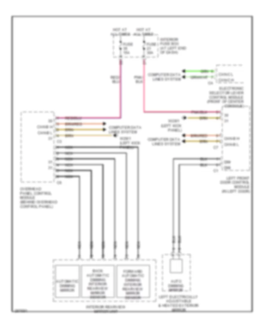
NAVIGATION
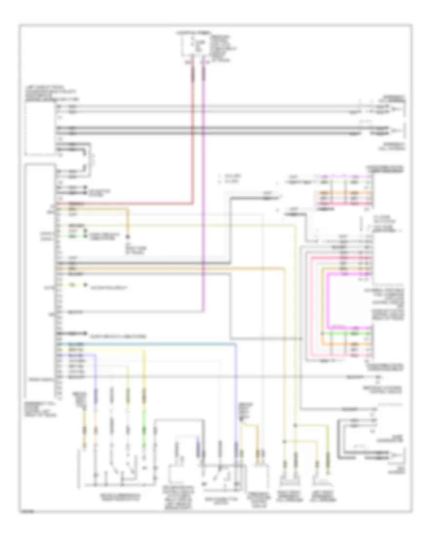
COMAND Actuation Wiring Diagram for Mercedes-Benz SLK350 2005
List of elements for COMAND Actuation Wiring Diagram for Mercedes-Benz SLK350 2005:
- (in center console) w12
- Accept/ terminate phone call pushbutton
- Audio gateway control module (if equipped) (right footwell)
- Can-b h
- Can-b l
- Cd changer (if equipped)
- Central gateway control module (back side of left underdash panel)
- Clock- spring
- Comand operating, display & control module
- Computer data lines system
- Emergency call system control unit (front of trunk)
- Fiber optical cable connector
- Fuse 5a
- Gnd
- Hot at all times
- Instrument cluster
- Interior fuse box (at left end of dash)
- Left multifunction steering wheel pushbutton group
- Left voltage distributor (can) connector
- Most
- Most in
- Most out
- Navigation processor (front center of trunk)
- Nca
- Pnk
- Pushbutton
- Red
- Right multifunction steering wheel pushbutton group
- Scroll forward/ back pushbutton
- Sdar control unit (if equipped) (left side of trunk)
- Steering column module (below steering wheel)
- System selection pushbutton
- Universal portable ctel interface (upci [uhi]) control module (if equipped) (front of trunk)
- Voice activation control module (if equipped)
- Volume control
- Wake-up
- Wake-up signal connector
- Walkman separation
Emergency Call Wiring Diagram for Mercedes-Benz SLK350 2005
List of elements for Emergency Call Wiring Diagram for Mercedes-Benz SLK350 2005:
- (behind right seat) w32/2
- (left side of trunk) phone/portable ctel/sth radio remote control antenna splitter
- 15r
- C25
- Can-d h
- Can-d l
- Computer data lines system
- Crash signal
- Driver-side sam control module with fuse & relay module (left rear of engine compt)
- E-net compensator
- Emergency call antenna
- Emergency call system control unit (front of trunk)
- Frequency switchover control module
- Fuse 20a
- Gnd
- Hands-free system microphone group
- Hot at all times
- Left front emergency call speaker
- Mb-info & breakdown assistance switch
- Mute
- Navigation circuit
- Navigation system
- Nca
- Pnk
- Rear sam control unit with fuse & relay module (front of trunk) c5
- Restraint systems control module
- Right front emergency call speaker
- Rod antenna
- S20
- Sos pushbutton switch
- Universal portable ctel interface (upci [uhi]) control module (or) voice activation control module (front of trunk)
- W/ upci
- W/ voice activation
- W/o upci
- W/o voice activation
- W7 (right side of trunk)
Navigation Wiring Diagram for Mercedes-Benz SLK350 2005
List of elements for Navigation Wiring Diagram for Mercedes-Benz SLK350 2005:
- (right side of trunk) w7
- Audio gateway control module (if equipped) (right footwell)
- Cd changer (if equipped)
- Emergency call system control unit (front of trunk)
- Fiber optical cable connector
- Fuse 7.5a
- Gnd
- Gps
- Gps ant.
- Gps antenna
- Gps antenna splitter
- Hot at all times
- Most
- Most in
- Most out
- Navigation processor (front center of trunk)
- Nca
- Pnk
- Radio & navigation unit
- Radio (or) radio & navigation unit (or) comand operating, display and control module
- Rear sam control unit w/ fuse & relay module (front of trunk)
- S19
- Sdar control unit (if equipped) (left side of trunk)
- Shield
- Universal portable ctel interface (upci [uhi]) control module (if equipped) (front of trunk)
- Voice activation control module (if equipped)
- Wake-up
- Wake-up signal connector
Voice Activation Wiring Diagram for Mercedes-Benz SLK350 2005
List of elements for Voice Activation Wiring Diagram for Mercedes-Benz SLK350 2005:
- (below steering wheel) steering column module
- (front center of trunk) navigation processor
- Audio gateway control module (if equipped) (right footwell)
- Can-b h
- Can-b l
- Cd changer (if equipped)
- Central gateway control module (back side of left underdash panel)
- Emergency call system control unit (front of trunk)
- Fiber optical cable connector
- Fuse 5a
- Gnd
- Hands-free system microphone group
- Hot at all times
- Instrument cluster
- Left voltage distributor (can) connector
- Mic. 1
- Mic. 2
- Mic. 3
- Most
- Most in
- Most out
- Nca
- Pnk
- Radio (or) radio and navigation unit (or) comand operating, display and control module
- Rear sam control unit with fuse & relay module (front of trunk)
- S17
- Sdar control unit (if equipped) (left side of trunk)
- Universal portable ctel interface (upci [uhi]) control module (if equipped) (front of trunk)
- Vcs (sbs) switch
- Voice activation control module
- W7 (right side of trunk)
- Wake up
- Wake-up
- Wake-up signal connector
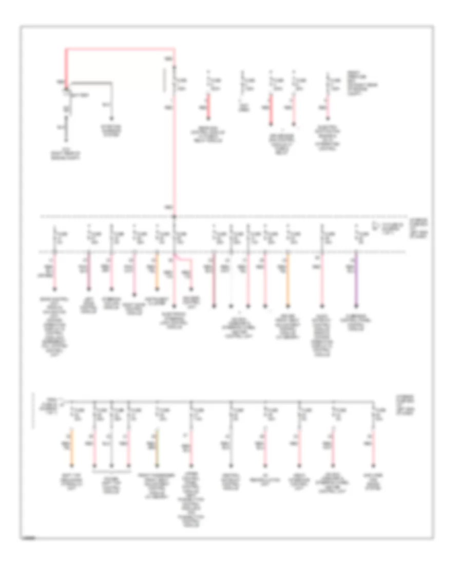
POWER DISTRIBUTION
Power Distribution Wiring Diagram for Mercedes-Benz SLK350 2005
List of elements for Power Distribution Wiring Diagram for Mercedes-Benz SLK350 2005:
- (diagram 1 of 1)
- (not used)
- Ac recirculation unit
- Amplifier for sound system
- Audio gateway control module, radio & comand operating display & control module
- Battery
- Central gateway control module
- Driver front seat adjustment control module (w/ memory)
- Driver-side sam control module w/ fuse & relay
- Eis (ezs) control
- Electric suction fan engine & ac w/ integrated control
- Electronic steering lock control module
- From fuse 22 a
- Front passenger front seat adjustment control module (w/ memory)
- Front pre-fuse box (on right rear of engine compt)
- Fuse 10a
- Fuse 125a
- Fuse 15a
- Fuse 200a
- Fuse 25a
- Fuse 30a
- Fuse 40a
- Fuse 5a
- Fuse 60a
- Fuse 7.5a
- Hs (sih) airscarf & steering wheel heater control unit
- Hs (sih), airscarf & steering wheel heater control unit
- Instrument cluster
- Interior fuse box (at left end of dash)
- Left door control module
- Media interface control unit
- Overhead control panel control module
- Power soft top control module
- Rear sam control module w/ fuse & relay module
- Red
- Right door control module
- Sdar control unit, radio & navigation unit, comand operating display & control module & emergency call system control unit
- Soft top mechanism hydraulic unit
- Starting/ charging system
- Steering column module
- To fuse 38 (diagram 1 of 1)
- Unit
- Upper control panel control module, heat pushbutton control module & aac pushbutton control module
- W10 (right rear of engine compt)
POWER DOOR LOCKS
Power Door Locks Wiring Diagram for Mercedes-Benz SLK350 2005
List of elements for Power Door Locks Wiring Diagram for Mercedes-Benz SLK350 2005:
- (left kick panel) w29/1
- (right kick panel) w29/2
- 15r
- Can b h
- Can b l
- Computer data lines system
- Fuse 15a
- Fuse 25a
- Fuse 5a
- Garage door opener transmitter unit
- Hot at all times
- Interior fuse box (at left end of dash)
- Left door cl (zv) motor (in left door)
- Left door control unit (in left door)
- Left door entrance & exit lamp
- Left ir receiver unit (left door handle)
- Lock
- Overhead control panel control module (behind overhead control panel)
- Rain/light sensor
- Red
- Right door cl (zv) motor (in right door)
- Right door control unit (in right door)
- Right door entrance & exit lamp
- Right ir receiver unit (right door handle)
- Unlock
- Upper control panel control unit (in center of dash)
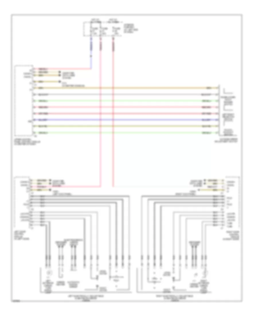
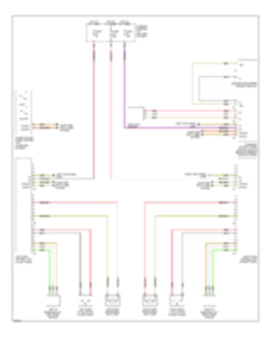
POWER MIRRORS
Electrochromic Mirror Wiring Diagram for Mercedes-Benz SLK350 2005
List of elements for Electrochromic Mirror Wiring Diagram for Mercedes-Benz SLK350 2005:
- (left kick panel)
- Auto dimming mirror
- Automatic dimming mirror
- Back automatic dimming interior rearview mirror sensor
- Can-b h
- Can-b l
- Can-c h
- Can-c l
- Computer data lines system
- Dim
- Electronic selector lever control module (front of center console)
- Forward automatic dimming interior rearview mirror sensor
- Fuse 15a
- Fuse 30a
- Hot at all times
- Interior fuse box (at left end of dash)
- Interior rearview mirror unit
- Left electrically adjustable & heated exterior mirror
- Left front door control module (in left door)
- Nca
- Overhead panel control module (behind overhead control panel)
- W29/1
- W29/1 (left kick panel)
Power Mirror Wiring Diagram for Mercedes-Benz SLK350 2005
List of elements for Power Mirror Wiring Diagram for Mercedes-Benz SLK350 2005:
- 58d
- Automatic dimming mirror
- Can-b h
- Can-b l
- Common
- Computer data lines system
- Defogger system
- Electrochromic mirror circuit
- Fold-in, fold-out switch
- Fuse 30a
- Fuse 7.5a
- Hot at all times
- In/out motor
- Interior fuse box (at left end of dash)
- L/r mtr
- Left door control module (in left door)
- Left electrically adjustable & heated exterior mirror
- Left exterior mirror turn signal lamp
- Left/right selection switch
- Mirror heater
- Outside mirror adjustment switch
- Raise/lower, in/out rocker switch
- Right door control module (in right door)
- Right electrically adjustable & heated exterior mirror
- Right exterior mirror turn signal lamp
- Turn
- U/d mtr
- Up/dn motor
- Upper control panel control module (in center of dash)
- W12 (in center console)
- W29/1 (left kick panel)
- W29/2 (right kick panel)
POWER SEATS
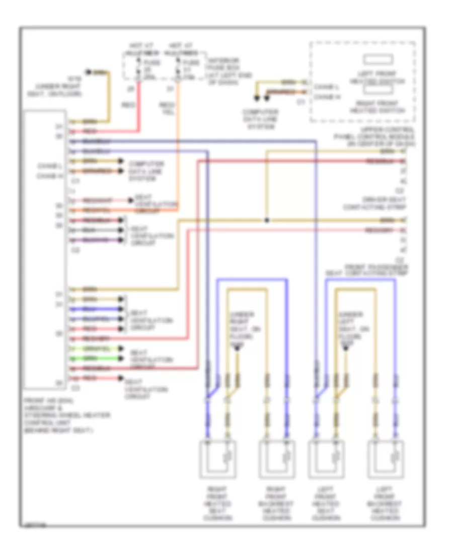
Heated Seats Wiring Diagram for Mercedes-Benz SLK350 2005
List of elements for Heated Seats Wiring Diagram for Mercedes-Benz SLK350 2005:
- (under left seat, on floor) w18
- (under right seat, on floor) w19
- Can-b h
- Can-b l
- Computer data line system
- Driver seat contacting strip
- Front hs (sih), airscarf & steering wheel heater control unit (behind right seat)
- Front passenger seat contacting strip
- Fuse 10a
- Fuse 25a
- Hot at all times
- Interior fuse box (at left end of dash)
- Left front backrest heated cushion
- Left front heated seat cushion
- Left front heated switch
- Red
- Right front backrest heated cushion
- Right front heated seat cushion
- Right front heated switch
- Seat ventilation circuit
- Upper control panel control module (in center of dash)
- W19 (under right seat, on floor)
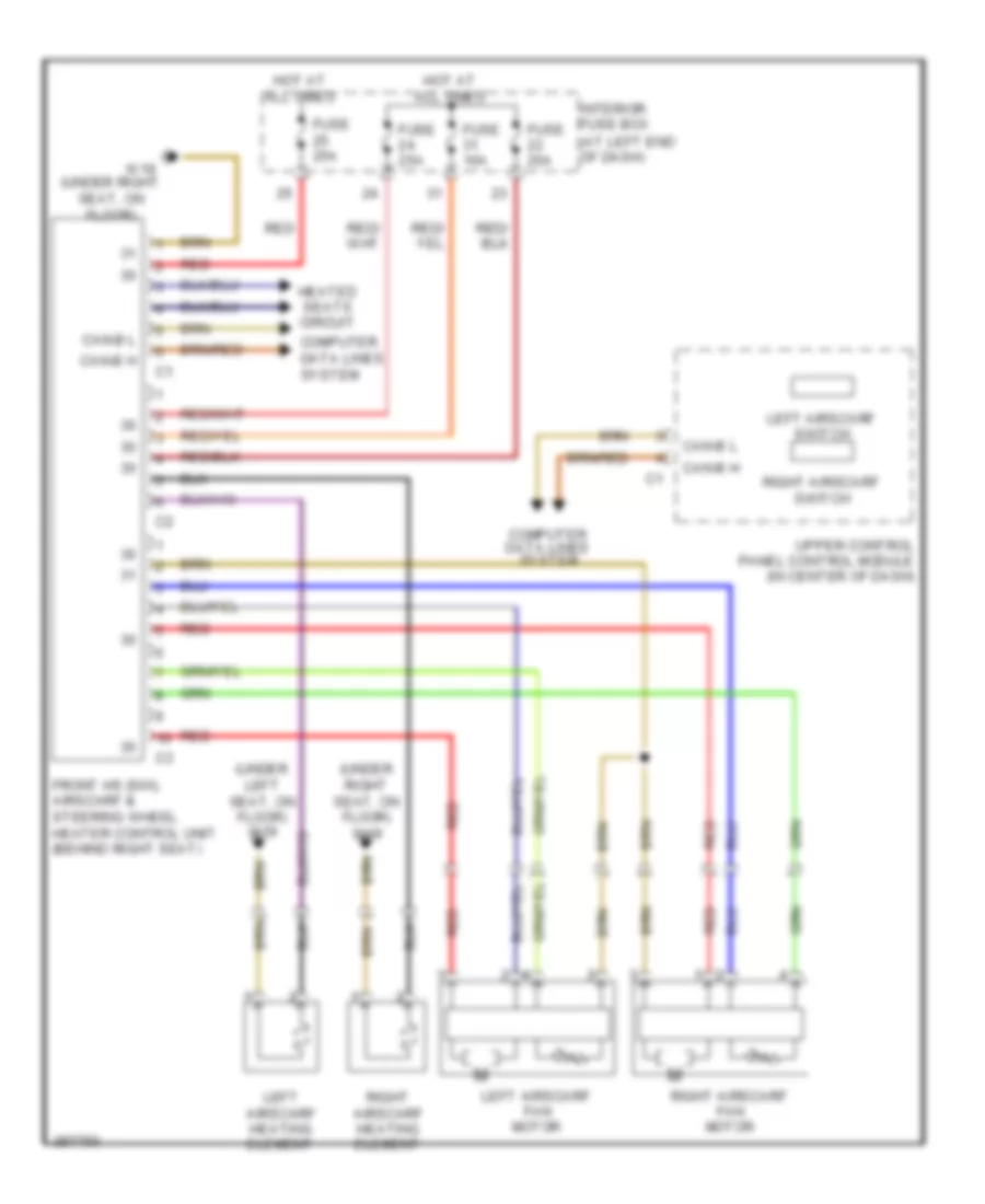
Seat Ventilation Wiring Diagram for Mercedes-Benz SLK350 2005
List of elements for Seat Ventilation Wiring Diagram for Mercedes-Benz SLK350 2005:
- (at left end of dash)
- (under left seat, on floor) w18
- (under right seat, on floor)
- (under right seat, on floor) w19
- Can-b h
- Can-b l
- Computer data lines system
- Front hs (sih), airscarf & steering wheel heater control unit (behind right seat)
- Fuse 10a
- Fuse 25a
- Heated seats circuit
- Hot at all times
- Interior fuse box
- Left airscarf fan motor
- Left airscarf heating element
- Left airscarf switch
- Red
- Right airscarf fan motor
- Right airscarf heating element
- Right airscarf switch
- Upper control panel control module (in center of dash)
- W19
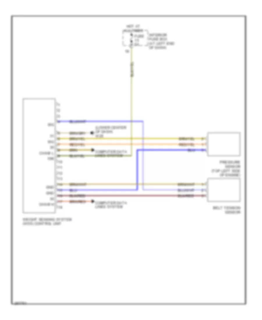
Weight Sensing System Wiring Diagram for Mercedes-Benz SLK350 2005
List of elements for Weight Sensing System Wiring Diagram for Mercedes-Benz SLK350 2005:
- (lower center of dash) w26
- 15r
- Belt tension sensor
- Can-b h
- Can-b l
- Computer data lines system
- Fuse 5a
- Gnd
- Hot at all times
- Interior fuse box (at left end of dash)
- Pressure sensor (top left side of engine)
- Sig
- Weight sensing system (wss) control unit
POWER TOP/SUNROOF
Power Top/Sunroof Wiring Diagram for Mercedes-Benz SLK350 2005
List of elements for Power Top/Sunroof Wiring Diagram for Mercedes-Benz SLK350 2005:
- (in center of dash)
- Can-b h
- Can-b l
- Close vario roof relay
- Computer data lines system
- Fuse 25a
- Fuse 40a
- Fuse 5a
- Hot at all times
- Interior fuse box (at left end of dash)
- Left"b" pillar)
- Nca
- Open vario roof relay
- Overhead control panel control module (behind overhead control panel)
- Pnk/red
- Power soft top control module
- Power windows system
- Red
- Soft top mechanism hydraulic unit
- Temperature sensor
- Trunk partition closed limit switch (left rear of trunk)
- Tubular frame locked limit switch (left rear of trunk)
- Tubular frame open limit switch (right rear of trunk)
- Upper control panel control unit
- Vario roof closed limit switch (on top left side of
- Vario roof locked limit switch (on top right side of
- Vario roof open/lowered limit switch (top of
- Vario roof solenoid valve
- Vario roof/ ata (edw) switch group
- W6 (left side of trunk)
- W7 (right side of trunk)
- Windshield frame)
POWER WINDOWS
Power Windows Wiring Diagram for Mercedes-Benz SLK350 2005
List of elements for Power Windows Wiring Diagram for Mercedes-Benz SLK350 2005:
- (+)
- (left side of trunk) w6
- 58d
- C11
- Can-b h
- Can-b l
- Computer data lines system
- Driver power window switch group
- Fh h
- Fh t
- Front passenger power window switch
- Fuse 25a
- Fuse 5a
- H (-)
- H signal 1
- H signal 2
- Hot at all times
- Interior fuse box (at left end of dash)
- Left door control module (in left door)
- Left front power window motor (in left door)
- Left power window switch
- Left rear power window motor (behind left quarter panel)
- Power soft top control module
- Red
- Right door control module (in right door)
- Right front power window motor (in right door)
- Right power window switch
- Right rear power window motor (behind right quarter panel)
- W29/1 (left kick panel)
- W29/2 (right kick panel)
RADIO
Auto Pilot System Wiring Diagram for Mercedes-Benz SLK350 2005
List of elements for Auto Pilot System Wiring Diagram for Mercedes-Benz SLK350 2005:
- (right footwell) w15/1
- Audio gateway control module (right footwell)
- C23
- Can-b h
- Can-b l
- Cd changer (if equipped)
- Center cockpit speaker
- Computer data lines system
- Fuse 40a
- Fuse 5a
- Fuse 7.5a
- Gnd
- Gps ant.
- Gps antenna
- Gps antenna splitter
- Hot at all times
- Interior fuse box (at left end of dash)
- Left antenna amplifier module (left side of trunk)
- Left door speaker group
- Left door tweeter
- Left rear speaker
- Left rear surround loudspeaker
- Most
- Most data bus circuit
- Most in
- Most out
- Mute
- Nca
- Pnk
- Radio & navigation unit
- Rear sam control unit w/ fuse & relay module (front of trunk)
- Red
- Right door speaker group
- Right door tweeter
- Right rear speaker
- Right rear surround loudspeaker
- Rod antenna
- S19
- Shield
- Sound amplifier microphone
- W12 (in center console)
- W29/2 (right kick panel)
- Wake-up
COMAND Actuation Wiring Diagram for Mercedes-Benz SLK350 2005
List of elements for COMAND Actuation Wiring Diagram for Mercedes-Benz SLK350 2005:
- (in center console) w12
- Accept/ terminate phone call pushbutton
- Audio gateway control module (if equipped) (right footwell)
- Can-b h
- Can-b l
- Cd changer (if equipped)
- Central gateway control module (back side of left underdash panel)
- Clock- spring
- Comand operating, display & control module
- Computer data lines system
- Emergency call system control unit (front of trunk)
- Fiber optical cable connector
- Fuse 5a
- Gnd
- Hot at all times
- Instrument cluster
- Interior fuse box (at left end of dash)
- Left multifunction steering wheel pushbutton group
- Left voltage distributor (can) connector
- Most
- Most in
- Most out
- Navigation processor (front center of trunk)
- Nca
- Pnk
- Pushbutton
- Red
- Right multifunction steering wheel pushbutton group
- Scroll forward/ back pushbutton
- Sdar control unit (if equipped) (left side of trunk)
- Steering column module (below steering wheel)
- System selection pushbutton
- Universal portable ctel interface (upci [uhi]) control module (if equipped) (front of trunk)
- Voice activation control module (if equipped)
- Volume control
- Wake-up
- Wake-up signal connector
- Walkman separation
MOST Data Bus Wiring Diagram for Mercedes-Benz SLK350 2005
List of elements for MOST Data Bus Wiring Diagram for Mercedes-Benz SLK350 2005:
- Audio gateway control module (if equipped) (right footwell)
- Cd changer (if equipped)
- Emergency call system control unit (front of trunk)
- Fiber optical cable connector
- Most
- Most in
- Most out
- Navigation processor (front center of trunk)
- Pnk
- Radio, radio & navigation unit & comand operating, display & control module
- Sdar control unit (if equipped) (left side of trunk)
- Universal portable ctel interface (upci (uhi)) control module (if equipped) (front of trunk)
- Voice activation control module (if equipped)
- Wake-up
- Wake-up signal connector
Radio Wiring Diagram for Mercedes-Benz SLK350 2005
List of elements for Radio Wiring Diagram for Mercedes-Benz SLK350 2005:
- C11
- C23
- Can-b h
- Can-b l
- Cd changer (if equipped)
- Center cockpit speaker
- Computer data lines system
- Driver-side sam control unit with fuse & relay module (left rear of engine compt)
- Fuse 10a
- Fuse 5a
- Fuse 7.5a
- Gnd
- Hot at all times
- Left antenna amplifier module (left side of trunk)
- Left door speaker group
- Left door tweeter
- Left rear speaker
- Most
- Most data bus circuit
- Most in
- Most out
- Mute
- Nca
- Pnk
- Radio
- Rear sam control unit with fuse & relay module (front of trunk)
- Right door speaker group
- Right door tweeter
- Right rear speaker
- Rod antenna
- S19
- Shield
- W12 (in center console)
- W29/2 (right kick panel)
- Wake-up
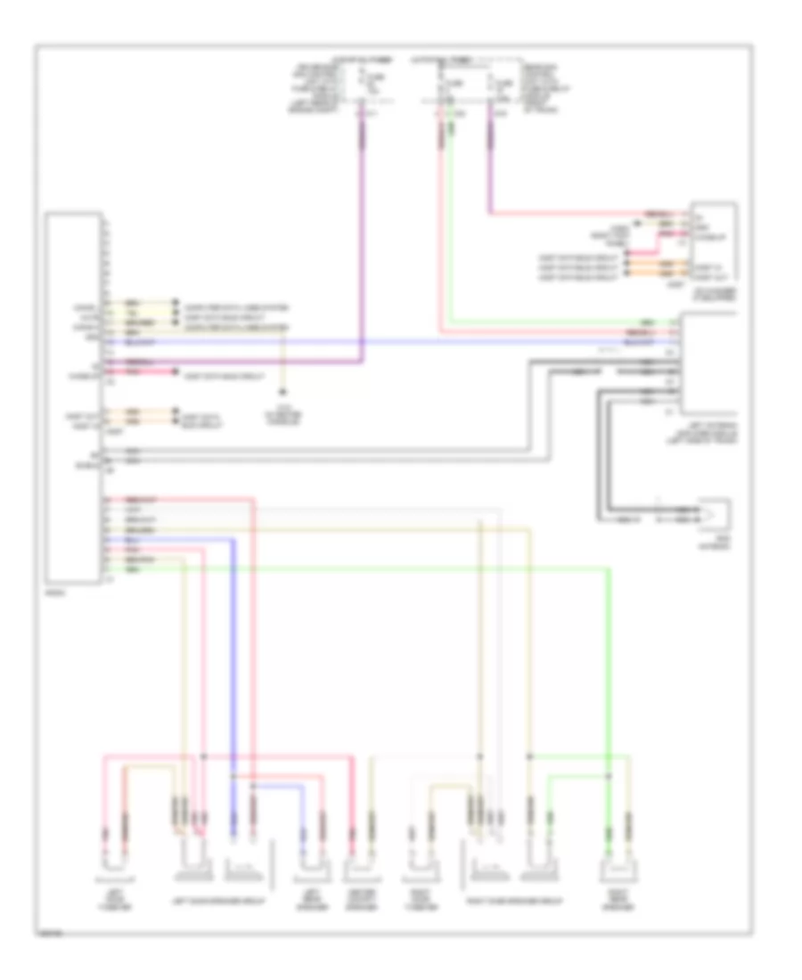
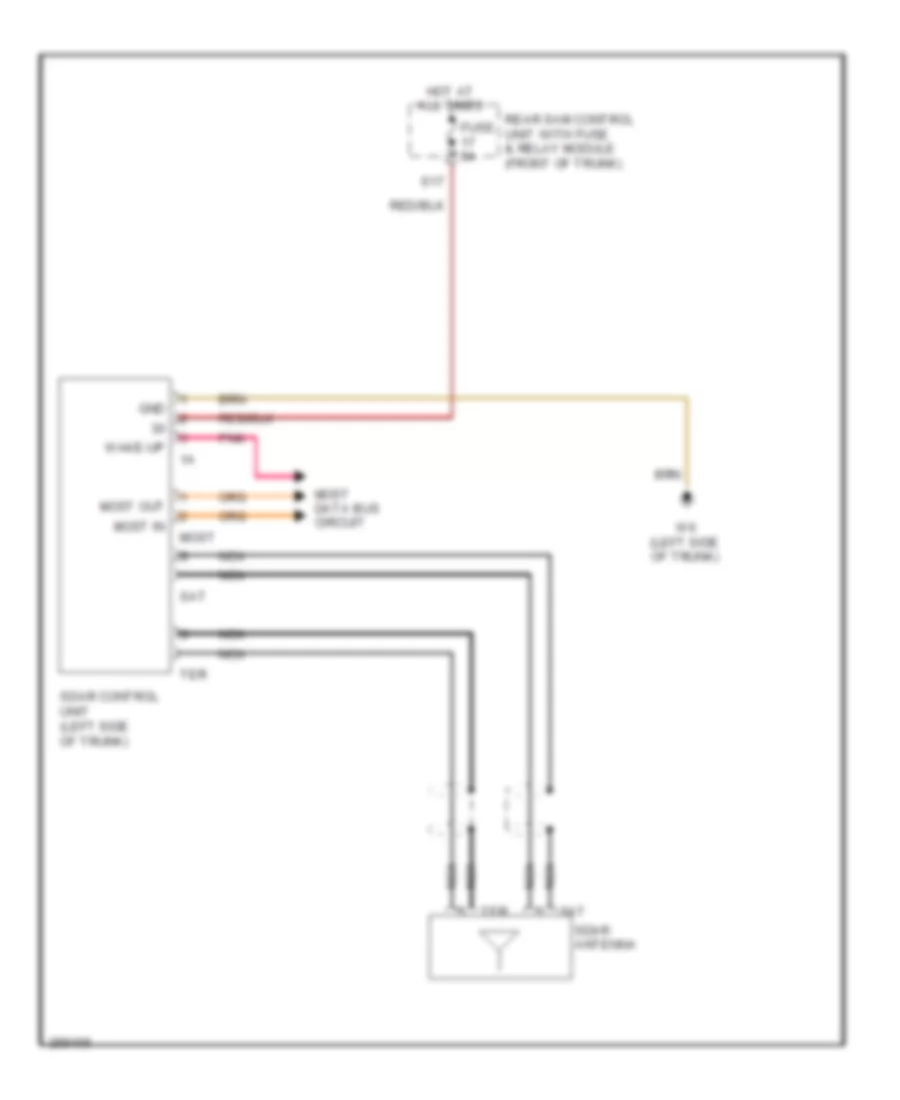
Satellite Radio Wiring Diagram for Mercedes-Benz SLK350 2005
List of elements for Satellite Radio Wiring Diagram for Mercedes-Benz SLK350 2005:
- Fuse 5a
- Gnd
- Hot at all times
- Most
- Most data bus circuit
- Most in
- Most out
- Nca
- Pnk
- Rear sam control unit with fuse & relay module (front of trunk)
- S17
- Sat
- Sdar antenna
- Sdar control unit (left side of trunk)
- Ter
- W6 (left side of trunk)
- Wake-up
Voice Activation Wiring Diagram for Mercedes-Benz SLK350 2005
List of elements for Voice Activation Wiring Diagram for Mercedes-Benz SLK350 2005:
- (below steering wheel) steering column module
- (front center of trunk) navigation processor
- Audio gateway control module (if equipped) (right footwell)
- Can-b h
- Can-b l
- Cd changer (if equipped)
- Central gateway control module (back side of left underdash panel)
- Emergency call system control unit (front of trunk)
- Fiber optical cable connector
- Fuse 5a
- Gnd
- Hands-free system microphone group
- Hot at all times
- Instrument cluster
- Left voltage distributor (can) connector
- Mic. 1
- Mic. 2
- Mic. 3
- Most
- Most in
- Most out
- Nca
- Pnk
- Radio (or) radio and navigation unit (or) comand operating, display and control module
- Rear sam control unit with fuse & relay module (front of trunk)
- S17
- Sdar control unit (if equipped) (left side of trunk)
- Universal portable ctel interface (upci [uhi]) control module (if equipped) (front of trunk)
- Vcs (sbs) switch
- Voice activation control module
- W7 (right side of trunk)
- Wake up
- Wake-up
- Wake-up signal connector
SHIFT INTERLOCK
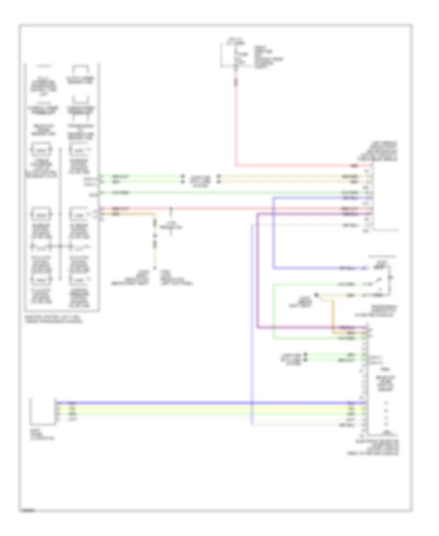
Shift Interlock Wiring Diagram for Mercedes-Benz SLK350 2005
List of elements for Shift Interlock Wiring Diagram for Mercedes-Benz SLK350 2005:
- (under right seat, on floor) w19
- C10
- C22
- Can-c h
- Can-c l
- Clutch pedal switch (m/t) (left footwell)
- Computer data lines system
- Diag
- Driver-side sam control module with fuse & relay module (left rear of engine compt)
- Electric control unit (vgs) (inside transmission housing)
- Electronic selector lever control module (front of center console)
- Fuse 10a
- Hot w/ circuit 87 relay energizied
- Internal speed sensor
- Kup2
- Late production
- Me-sfi (me) control module (on center of engine)
- Output speed sensor
- Red
- Shift lever illumination
- Start enable clutch pedal switch (m/t) (left footwell)
- Transmission mode switch (in center console)
- Turbine speed sensor
- W16/3 (on left front strut tower)
STARTING/CHARGING
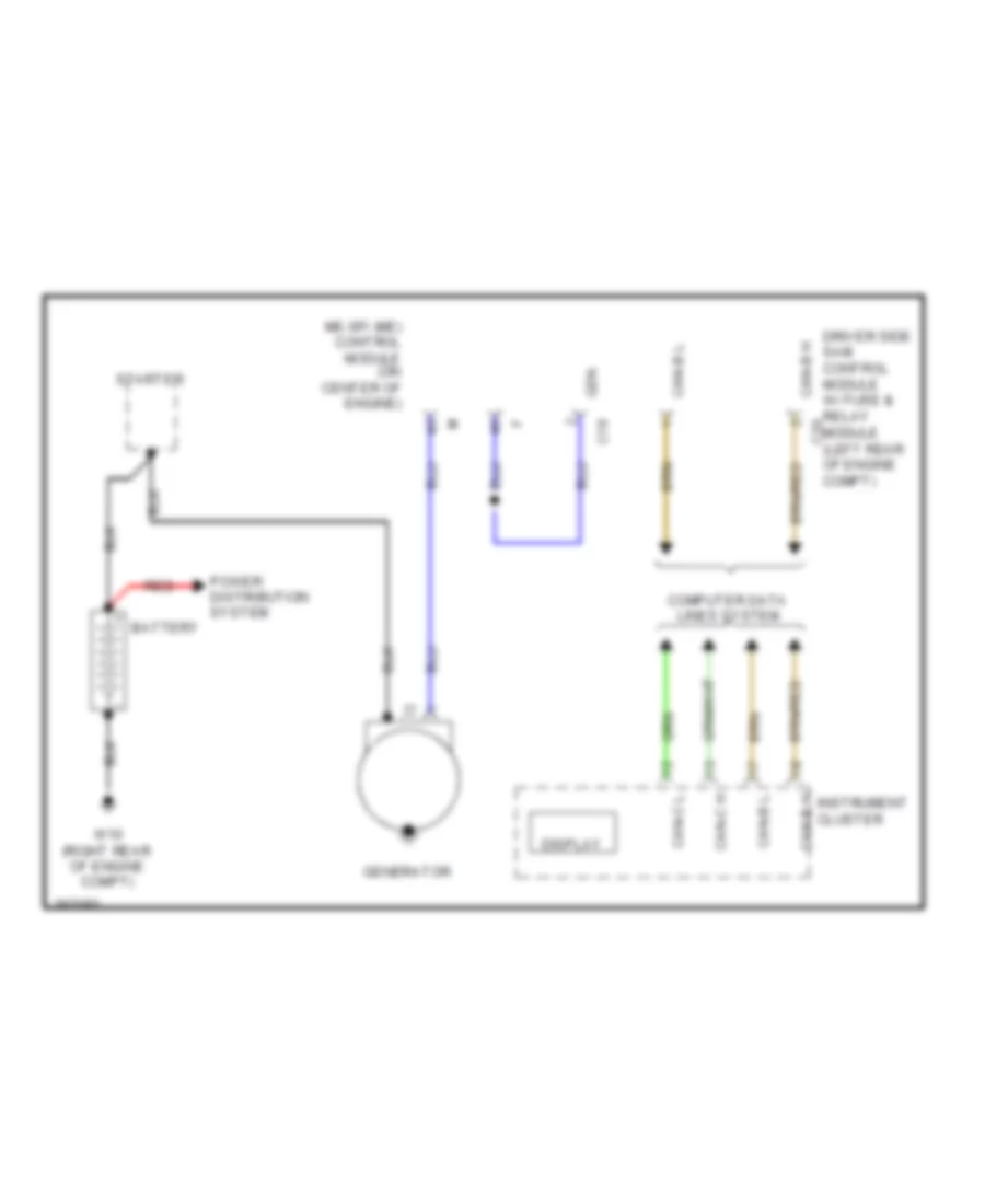
Charging Wiring Diagram for Mercedes-Benz SLK350 2005
List of elements for Charging Wiring Diagram for Mercedes-Benz SLK350 2005:
- Battery
- C18
- Can-b h
- Can-b l
- Can-c h
- Can-c l
- Computer data lines system
- Display
- Driver side sam control module w/ fuse & relay c20 module (left rear of engine compt)
- Gen
- Generator
- Instrument cluster
- Me-sfi (me) control module (on center of engine)
- Power distribution system
- Red
- Starter
- W10 (right rear of engine compt)
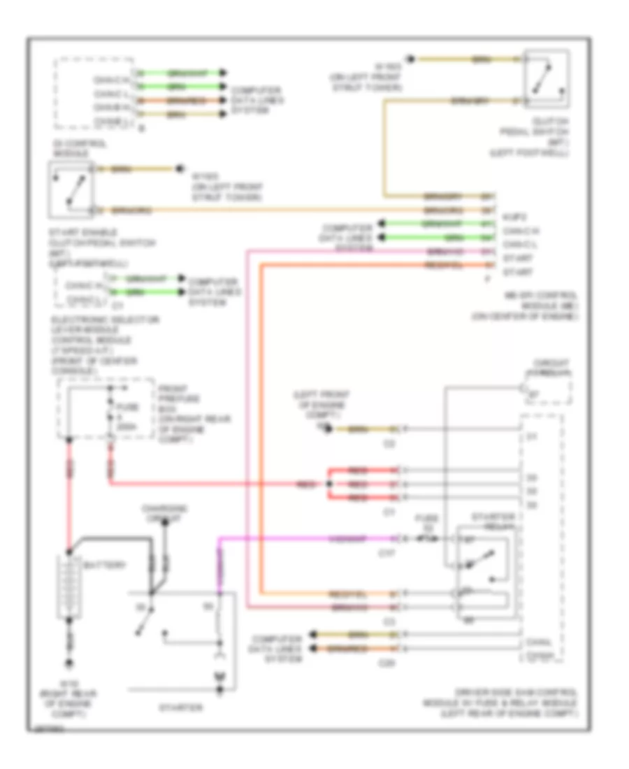
Starting Wiring Diagram for Mercedes-Benz SLK350 2005
List of elements for Starting Wiring Diagram for Mercedes-Benz SLK350 2005:
- (left front of engine compt) w9
- Battery
- C17
- C20
- Can-b h
- Can-b l
- Can-c h
- Can-c l
- Can-h
- Can-l
- Charging circuit
- Circuit 15 relay
- Clutch pedal switch (m/t) (left footwell)
- Computer data lines system
- Di control module
- Driver side sam control module w/ fuse & relay module (left rear of engine compt)
- Electronic selector lever module control module (7 speed a/t) (front of center console)
- Front prefuse box (on right rear of engine compt)
- Fuse 15a
- Fuse 200a
- Kup2
- Me-sfi control module (me) (on center of engine)
- Red
- Start
- Start enable clutch pedal switch (m/t) (left footwell)
- Starter
- Starter relay
- W10 (right rear of engine compt)
- W16/3 (on left front strut tower)
SUPPLEMENTAL RESTRAINTS
Supplemental Restraints Wiring Diagram for Mercedes-Benz SLK350 2005
List of elements for Supplemental Restraints Wiring Diagram for Mercedes-Benz SLK350 2005:
- (pins 5 thru 32: not used)
- 15r
- Ab1, bf+
- Ab1, bf-
- Ab1, fa+
- Ab1, fa-
- Ab2, bf+
- Ab2, bf-
- Ab2, fa+
- Ab2, fa-
- Can h
- Can l
- Clock- spring
- Computer data lines system
- Crash sig
- Driver airbag squib 1 (in steering wheel)
- Driver airbag squib 2 (in steering wheel)
- Driver buckle etr squib (right side of drivers seat)
- Driver kneebag squib (at left footwell)
- Driver seat belt buckle restraint systems switch
- Driver seat belt force limiter (lower left "b" pillar)
- Driver side airbag sensor (at left door sill)
- Driver side airbag squib (side of drivers seat)
- Driver-side sam control module w/ fuse & relay module (left rear of engine compt)
- Drvr belt
- Emergency call system control unit (front of trunk)
- Etr db+
- Etr db-
- Etr pb+
- Etr pb-
- Front passenger airbag squib 1 (behind right side of dash)
- Front passenger airbag squib 2 (behind right side of dash)
- Front passenger kneebag squib (lower right side of dash)
- Front passenger seat belt force limiter (lower right "b" pillar)
- Kb, bf+
- Kb, bf-
- Kb, f+
- Kb, f-
- Left frontal accel- eration sensor (behind left side of grille)
- Limiter d+
- Limiter d-
- Limiter p+
- Limiter p-
- Pass belt
- Passenger buckle etr squib (left side of passengers seat)
- Passenger seat belt buckle restraint systems switch
- Passenger seat occupied & child seat recognition sensor (in right seat)
- Passenger side airbag sensor (at right door sill)
- Passenger side airbag squib (side of passengers seat)
- Red
- Restraint systems control module (below front of center console)
- Right frontal accel- eration sensor (behind right side of grille)
- Sb akse bf
- Sb, bf+
- Sb, bf-
- Sb, f+
- Sb, f-
- Sbs li
- Sbs re
- Steering column module
- Upfront l
- Upfront r
- W26 (lower center of dash)
TRANSMISSION
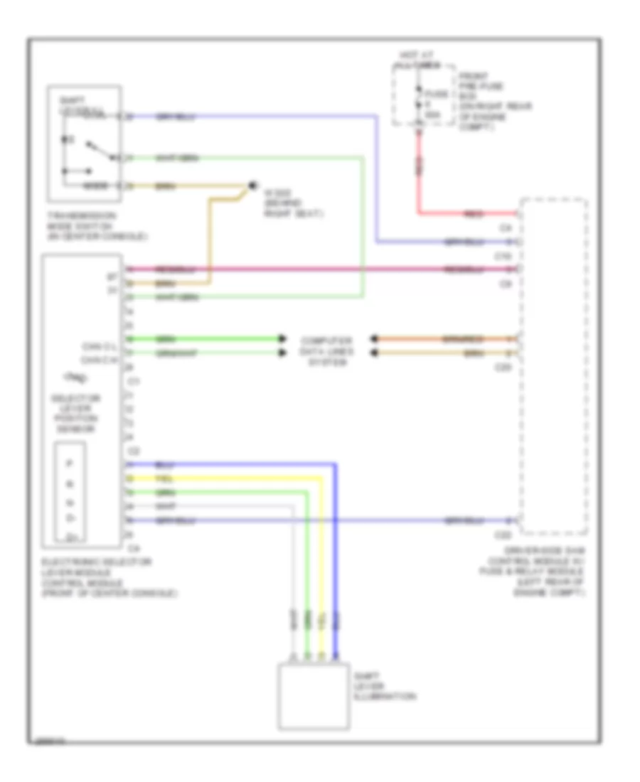
Transmission Wiring Diagram, 5 Speed A/T for Mercedes-Benz SLK350 2005
List of elements for Transmission Wiring Diagram, 5 Speed A/T for Mercedes-Benz SLK350 2005:
- C10
- C20
- C22
- Can c h
- Can c l
- Computer data lines system
- Driver-side sam control module w/ fuse & relay module (left rear of engine compt)
- Electronic selector lever module control module (front of center console)
- Front pre-fuse box (on right rear of engine compt)
- Fuse 60a
- Hot at all times
- Mode
- Red
- Selector lever position sensor
- Shift lever ill
- Shift lever illumination
- Transmission mode switch (in center console)
- W32/2 (behind right seat)
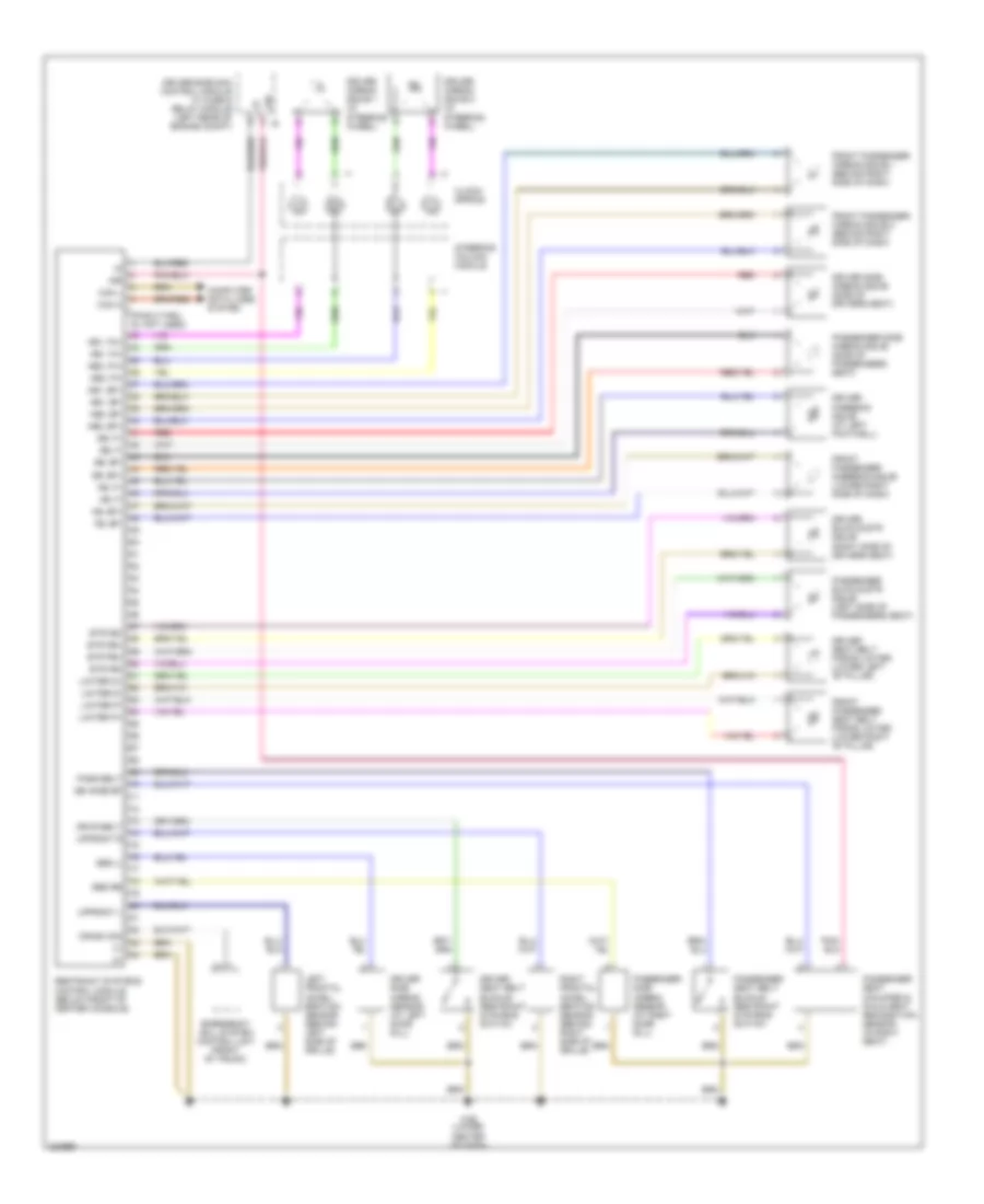
Transmission Wiring Diagram, 7 Speed A/T for Mercedes-Benz SLK350 2005
List of elements for Transmission Wiring Diagram, 7 Speed A/T for Mercedes-Benz SLK350 2005:
- (behind
- (in center console)
- (left rear of engine compt) driver-side sam control module w/ fuse & relay module
- B1 brake control solenoid valve (vgs)
- B2 brake control solenoid valve (vgs)
- B3 brake control solenoid valve (vgs)
- C10
- C20
- C22
- Can c h
- Can c l
- Computer data lines system
- Diag
- Electric control unit (vgs) (inside transmission housing)
- Electronic selector lever module control module (front of center console)
- Front pre-fuse box (on right rear of engine compt)
- Fully integrated transmission control (vgs) unit
- Fuse 60a
- Hot at all times
- Internal speed sensor (vgs)
- K1 clutch control solenoid valve (vgs)
- K2 clutch control solenoid valve (vgs)
- K3 clutch control solenoid valve (vgs)
- Late production
- Mode
- Output speed sensor (vgs)
- Red
- Right seat)
- Selection range sensor (vgs)
- Selector lever position sensor
- Shift lever ill
- Shift lever illumination
- Torque converter lock up clutch control solenoid valve
- Transmission mode switch
- Transmission oil temperature sensor (vgs)
- Turbine speed sensor (vgs)
- W29/1 (late production) (left kick panel)
- W32/2
- W32/2 (early production) (behind right seat)
- Working pressure control solenoid valve (vgs)
TRUNK, TAILGATE, FUEL DOOR
Trunk, Tailgate, Fuel Door Wiring Diagram for Mercedes-Benz SLK350 2005
List of elements for Trunk, Tailgate, Fuel Door Wiring Diagram for Mercedes-Benz SLK350 2005:
- C21
- Can-bh
- Can-bl
- Computer data lines system
- Front prefuse box (on right rear of engine compt)
- Fuse 200a
- Hot at all times
- Left door contact switch
- Rear sam control module w/ fuse & relay module (front of trunk)
- Red
- Right door contact switch
- Rotary tumbler/ trunk lid microswitch (rear center of trunk lid)
- Trunk lid emergency release switch (rear of trunk lid)
- Trunk lid external operation switch (rear center of trunk lid)
- W6 (left side of trunk)
- W7 (right side of trunk)
WARNING SYSTEMS
Warning Systems Wiring Diagram for Mercedes-Benz SLK350 2005
List of elements for Warning Systems Wiring Diagram for Mercedes-Benz SLK350 2005:
- (left side of trunk) w6
- 15g
- 30z
- 31e
- Abs malfunction indicator lamp
- Air bag indicator & warning lamp
- Ambient temperature display temperature sensor
- Audible turn signal indicator
- Bbv m
- Bbvs
- Brake fluid & parking brake warning lamp
- Brake fluid indicator switch (on brake fluid reservoir)
- Brake indicator light
- C12
- C19
- C20
- Can-b h
- Can-b l
- Can-c h
- Can-c l
- Check engine malfunction indicator lamp
- Computer data lines system
- Coolant level indicator switch (right front wheelwell)
- Driver side seat belt buckle restraint systems switch (right side of driver's seat)
- Driver-side sam control module w/ fuse & relay module (left rear of engine compt)
- Esp and bas control unit (left front of engine compartment)
- Esp warning lamp
- Front prefuse box (on right rear of engine compt)
- Fuel level sensor (in fuel tank)
- Fuel reserve indicator lamp
- Fuse 200a
- Fuse 5a
- Fuse 60a
- Fuse 7.5a
- Hot at all times
- Hot in on or start
- Instrument cluster
- Interior fuse box (at left end of dash)
- Left turn signal indicator lamp
- Lower multifunction display
- Nca
- Parking brake indicator switch (between seats)
- Rear sam control unit with fuse & relay module (front of trunk)
- Red
- Restraint systems control unit (behind front of center console)
- Right front brake pad contact sensor
- Right turn signal indicator lamp
- Seat belt reminder lamp
- Upper multifunction display
- W12 (in center console)
- W16/3 (on left front strut tower)
- W26 (lower center of dash)
- W32/2 (behind right seat)
- W6 (left side of trunk)
- Warning buzzer
- Windshield washer fluid level indicator switch (right front wheelwell)
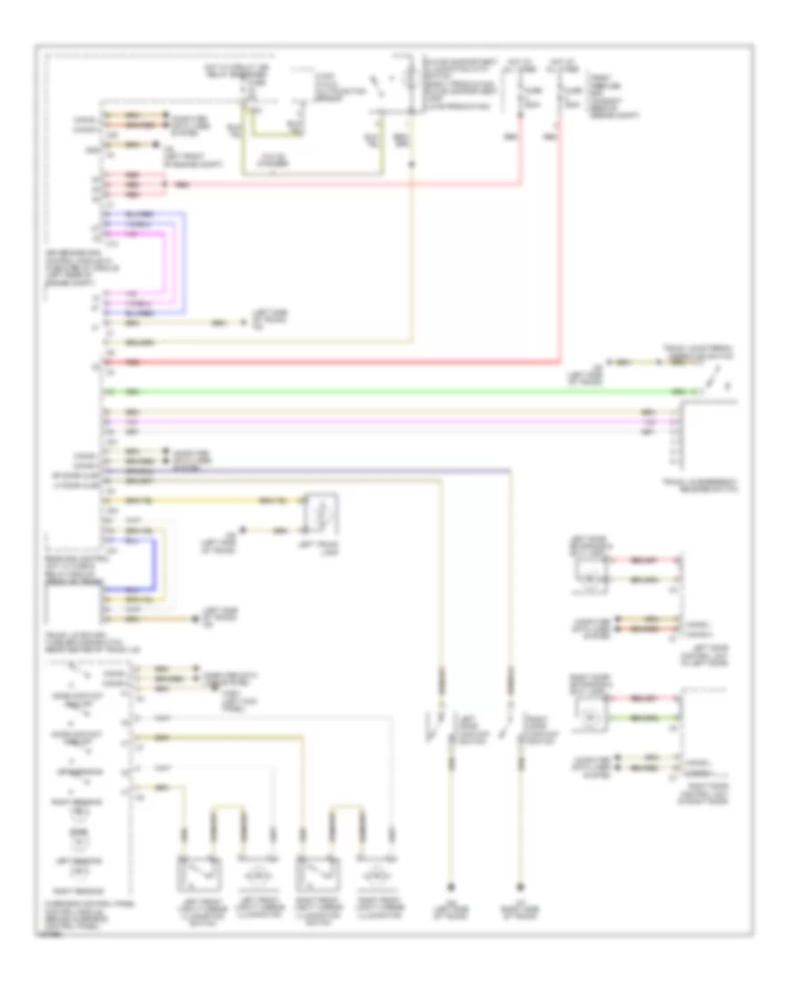
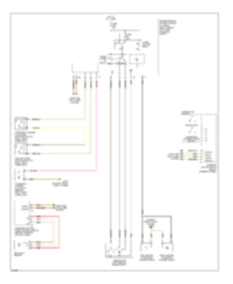
WIPER/WASHER
Front Wiper/Washer Wiring Diagram for Mercedes-Benz SLK350 2005
List of elements for Front Wiper/Washer Wiring Diagram for Mercedes-Benz SLK350 2005:
- (on right front strut tower) w16/4
- 31b
- 87a
- Can-b h
- Can-b l
- Can-c h
- Can-c l
- Combination switch
- Computer data lines system
- Coolant level indicator switch (right front wheelwell)
- Driver side sam control module w/ fuse & relay module (left rear of engine compt)
- Fuse 40a
- Fuse 43b 15a
- Hot at all times
- Left heated windshield washer nozzle
- Overhead control panel control module (behind overhead control panel)
- Park
- Rain/light sensor
- Red
- Right heated windshield washer nozzle
- Steering column module (below steering wheel)
- W16/4 (on right front strut tower)
- Windshield washer fluid level indicator switch (right front wheelwell)
- Windshield washer fluid pump (rear of right front wheel well)
- Windshield washer system switch
- Wipe switch
- Wiper motor (left rear of engine compt)
- Wiper on & off relay
- Wiper stage 1-2 relay
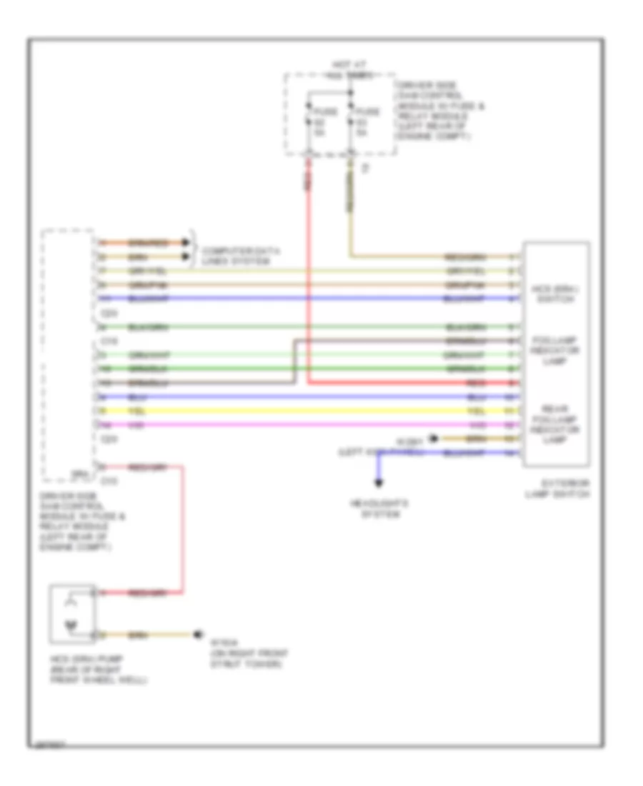
Headlamp Washer Wiring Diagram for Mercedes-Benz SLK350 2005
List of elements for Headlamp Washer Wiring Diagram for Mercedes-Benz SLK350 2005:
- C15
- C19
- C20
- Computer data lines system
- Driver side sam control module w/ fuse & relay module (left rear of engine compt)
- Exterior lamp switch
- Fog lamp indicator lamp
- Fuse 5a
- Hcs (sra) pump (rear of right front wheel well)
- Hcs (sra) switch
- Headlights system
- Hot at all times
- Rear fog lamp indicator lamp
- Red
- Sra
- W16/4 (on right front strut tower)
- W29/1 (left kick panel)

 Čeština
 Dansk
Dansk Deutsch
 Ελληνικά
 English
 English
 Español
 Suomi
Suomi Français
 Français
 עברית
עברית Hrvatski
 Magyar
 Italiano
 日本語
日本語 한국어
한국어 Nederlands
 Português
 Português
 Română
 Русский
 Slovenčina
 Slovenščina
 Svenska
 Türkçe
 中文 (中国)