AIR CONDITIONING
3.0L
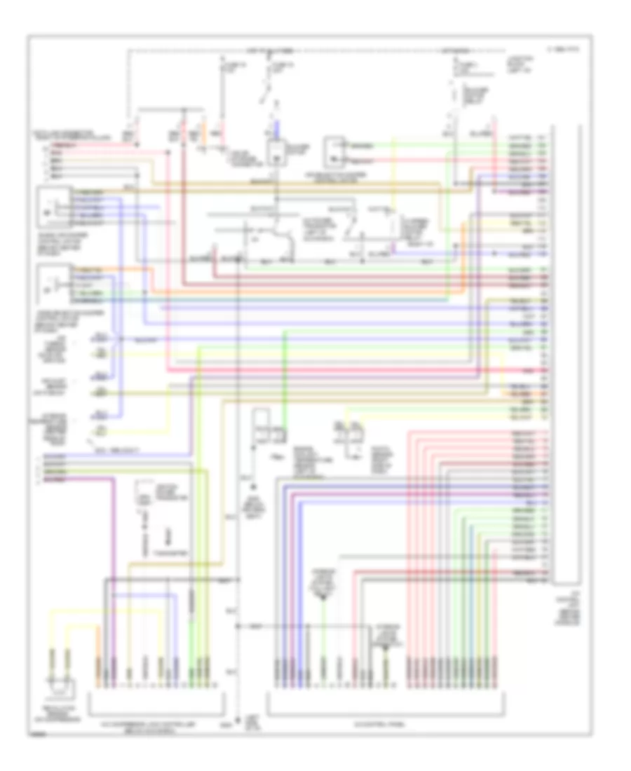
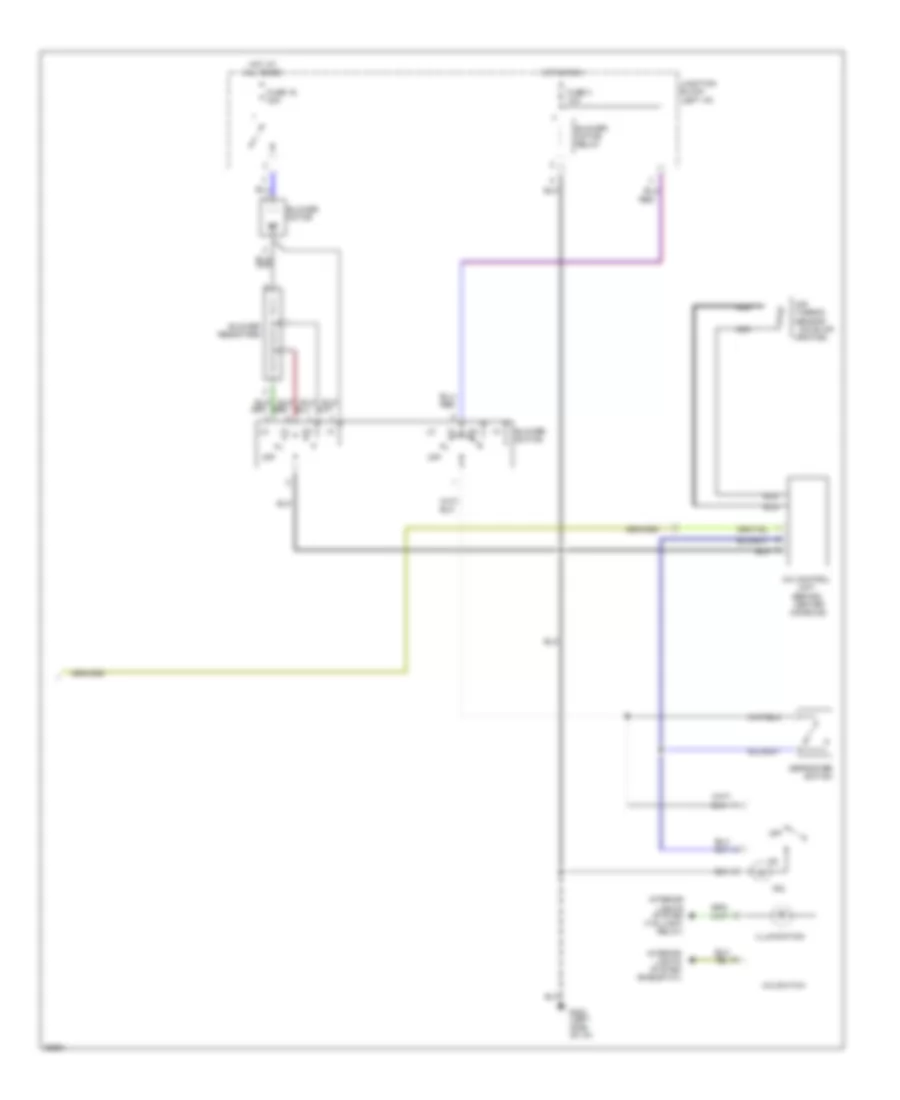
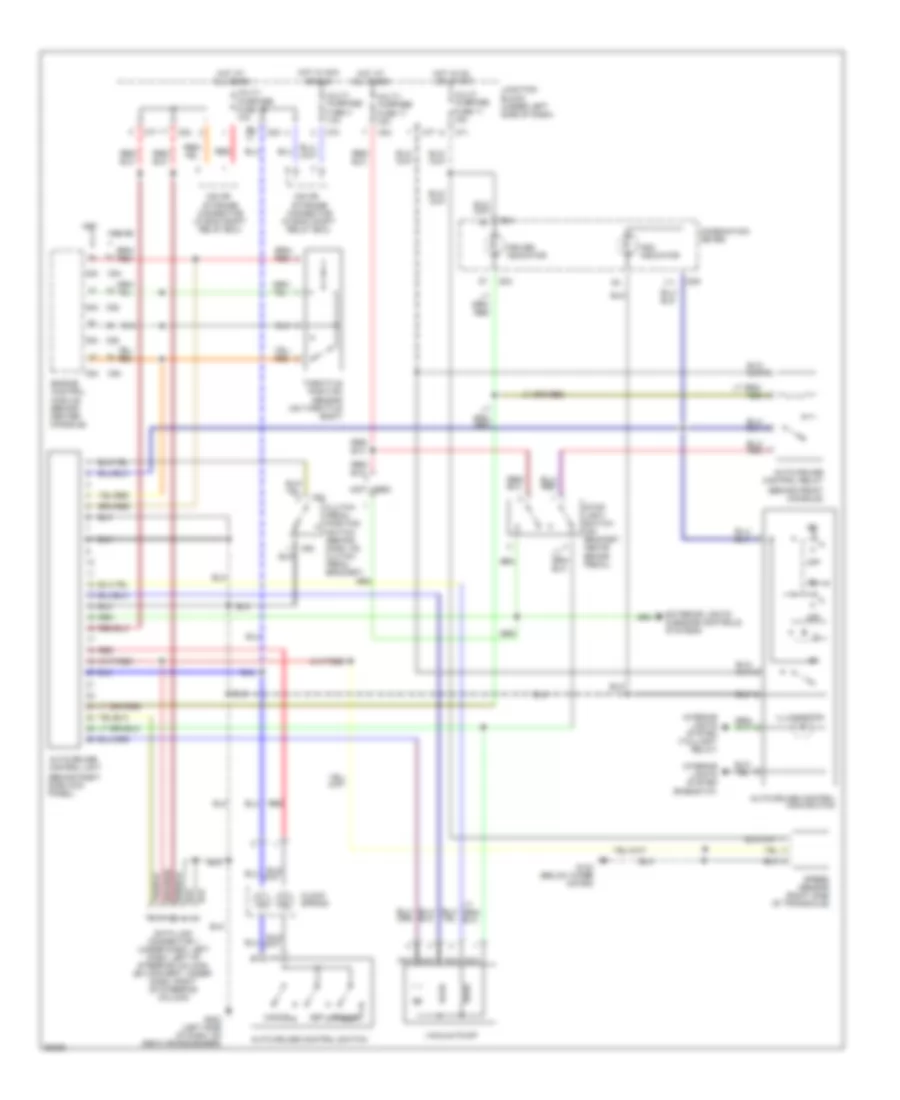
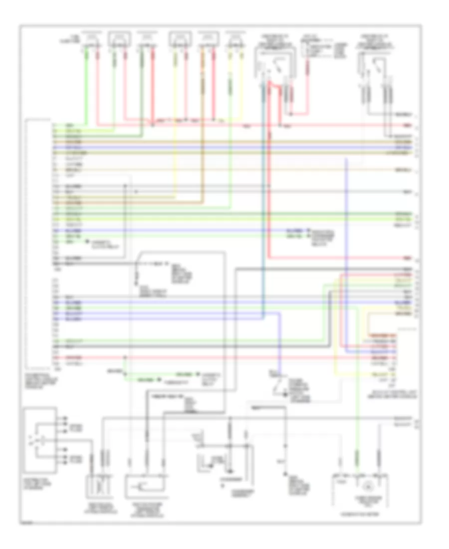
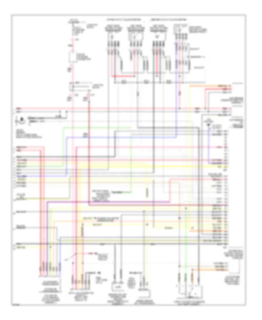
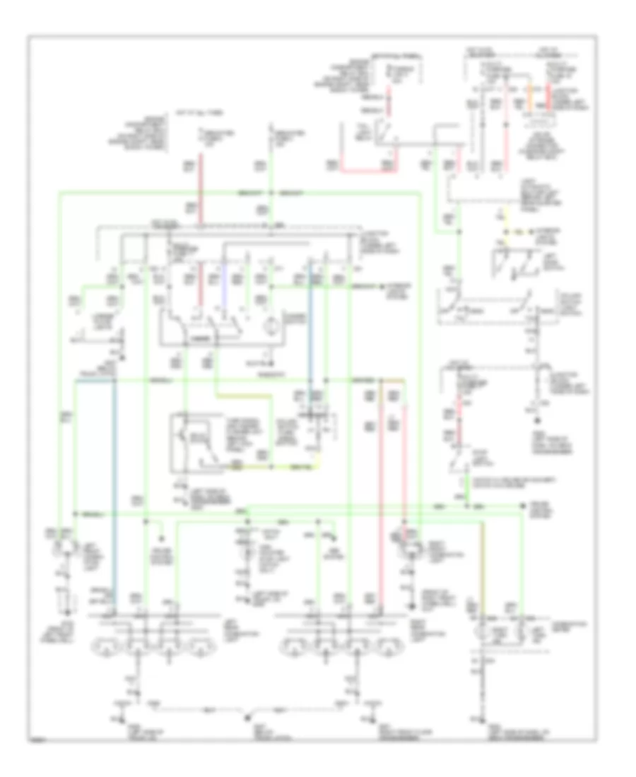
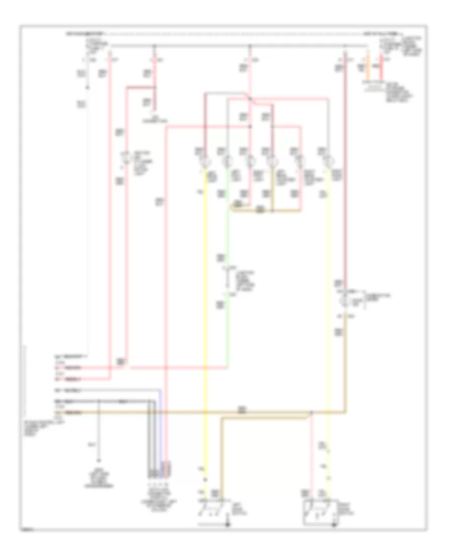
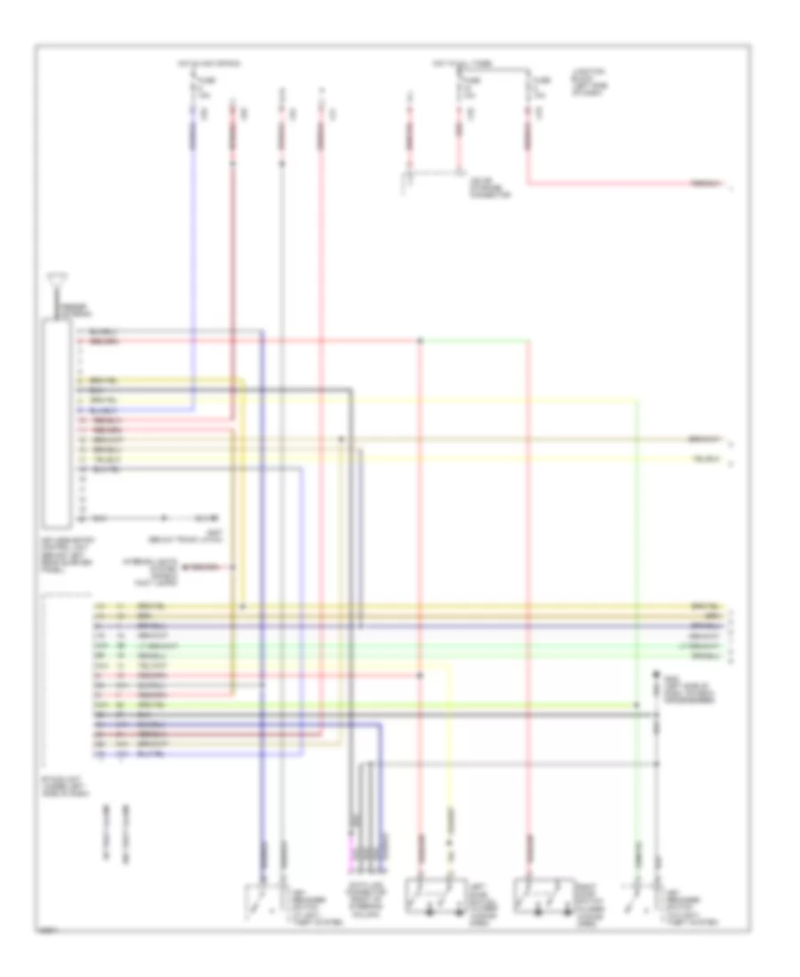
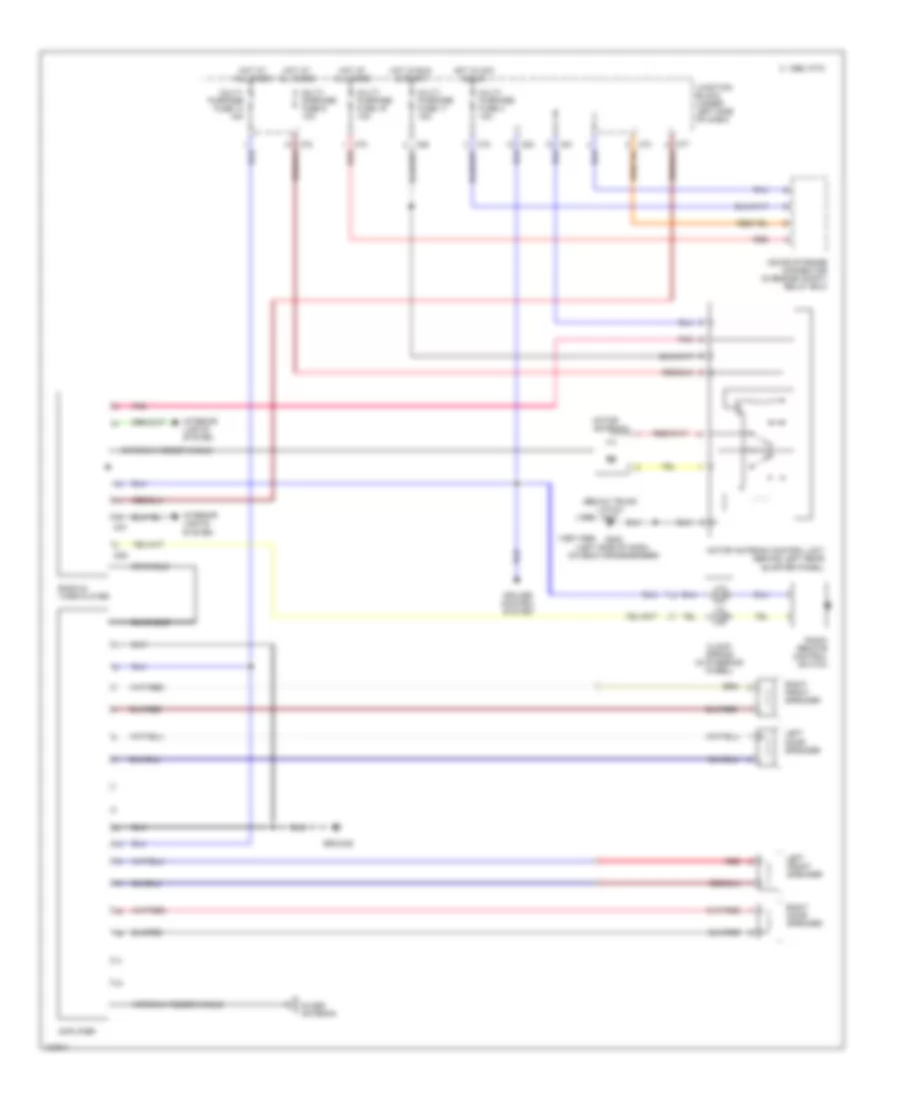
3.0L DOHC Turbo, Air Conditioning Wiring Diagrams (1 of 2) for Mitsubishi 3000GT 1997 3000
 https://portal-diagnostov.com/license.html
Automotive Electricians Portal FZCO
Automotive Electricians Portal FZCO
https://portal-diagnostov.com/license.html
https://portal-diagnostov.com/license.html
Automotive Electricians Portal FZCO
Automotive Electricians Portal FZCO
List of elements for 3.0L DOHC Turbo, Air Conditioning Wiring Diagrams (1 of 2) for Mitsubishi 3000GT 1997 3000:
- (left front fender)
- (not used)
- (on compressor)
- (open above
- (open above 155 c)
- (open below
- (part of radiator fan assembly)
- (right side of safety wall)
- 210 kpa)
- 2700 kpa)
- 4a/t control module (behind center console)
- A/t only
- All times
- C 1995 vftc
- Centralized junction box (right side engine compt)
- Condenser fan motor
- Dual pressure switch (left front engine compt)
- Engine control module (behind center console)
- Engine coolant level switch
- Engine coolant temperature sensor (right side of engine)
- Fuse 11 15a
- Fuse 3 10a
- Fuse 8 20a
- Fuse 9 10a
- Fuse/ relay block (left side engine compt)
- Fusible link 5 40a
- G100
- G101 (right front fender)
- G123
- Hi speed condenser fan motor relay
- Hi speed radiator fan motor relay
- Hot at
- Hot in run
- Hot in run or start
- Instrument cluster
- Junction block (left i/p)
- Lo speed condenser fan motor relay
- Lo speed radiator fan motor relay
- Magnetic clutch (on compressor)
- Magnetic clutch relay
- Radiator fan motor
- Radiator ind.
- Resistor
- Solid state
- Speed sensor
- Thermostat
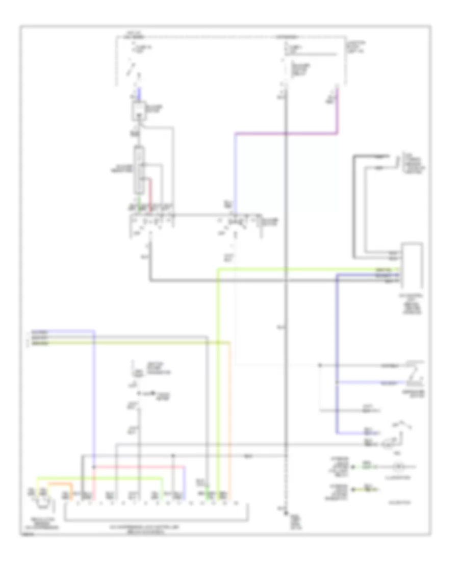
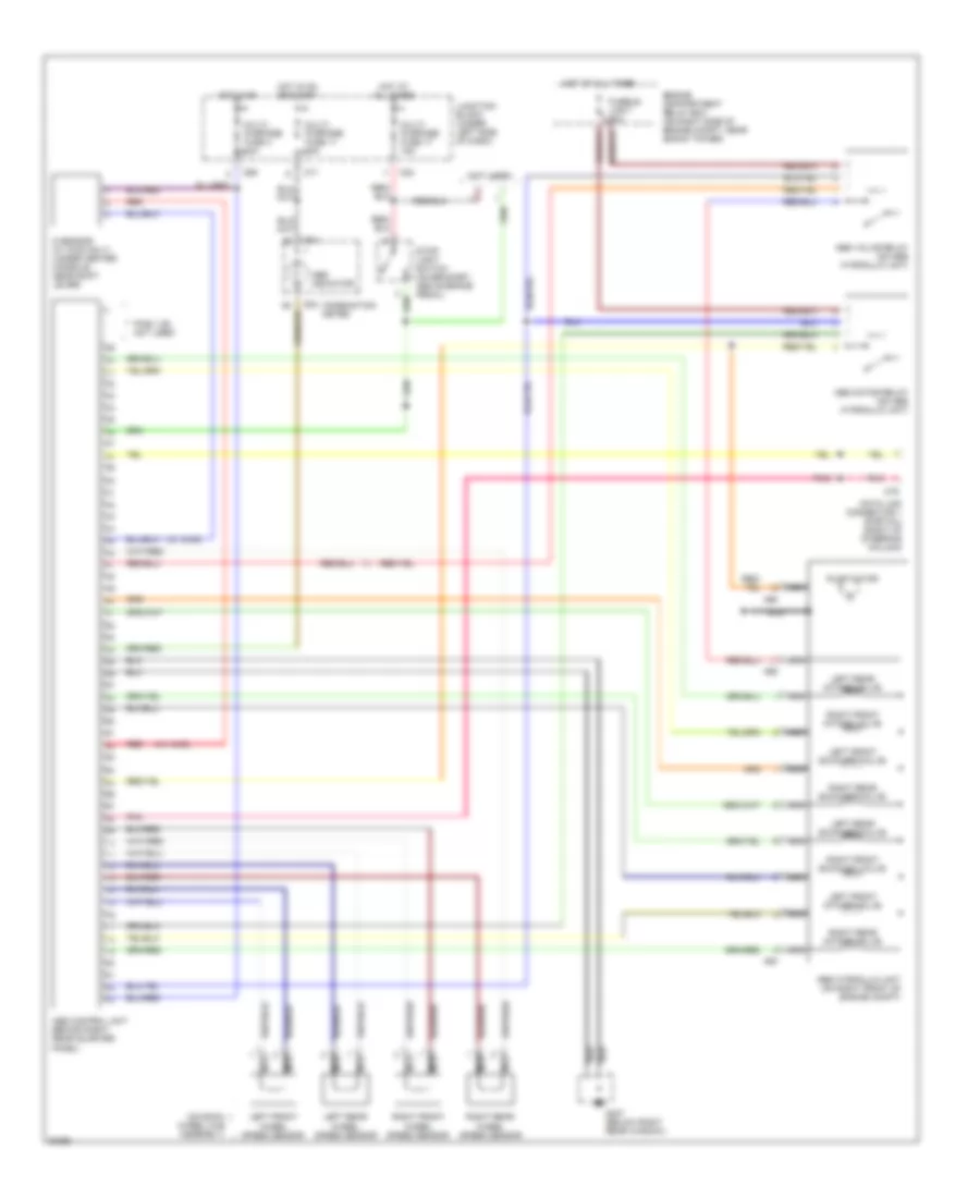
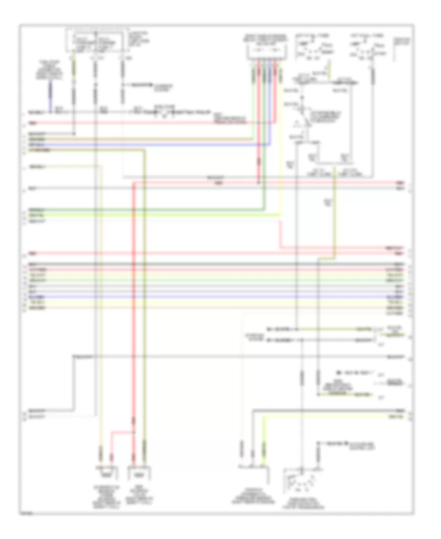
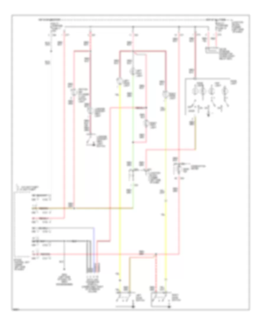
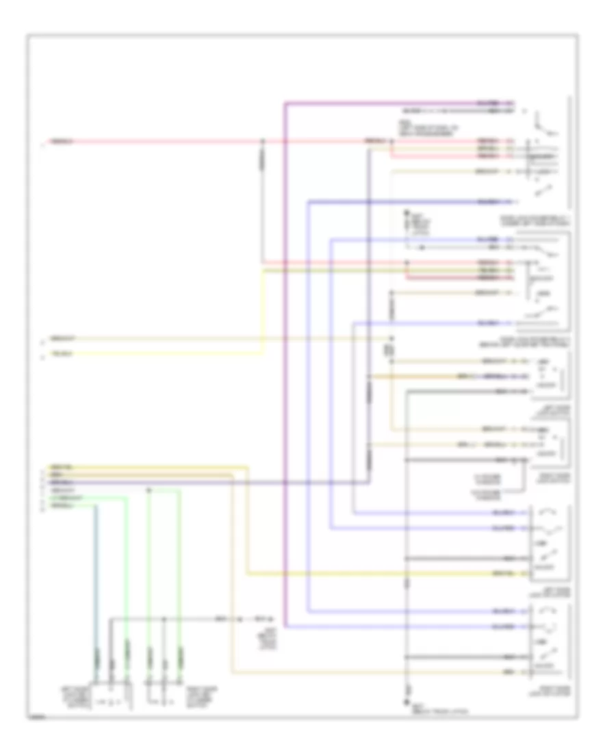
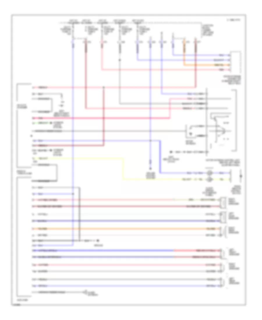
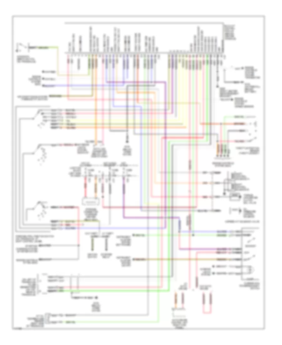
3.0L DOHC Turbo, Air Conditioning Wiring Diagrams (2 of 2) for Mitsubishi 3000GT 1997 3000
List of elements for 3.0L DOHC Turbo, Air Conditioning Wiring Diagrams (2 of 2) for Mitsubishi 3000GT 1997 3000:
- (behind center of dash)
- (below glove box)
- (left of
- (left side of i/p)
- (on compressor)
- (on evap-
- (on plenum)
- (rheostat)
- (right i/p)
- (right of steering column)
- (taillight
- A/c compressor lock controller
- A/c control panel
- A/c control unit (behind center console)
- A/c power transistor
- Air
- Air inlet
- Air selection damper control motor
- Blend air damper
- Blower motor
- Blower motor relay
- C 1995 vftc
- Control motor
- Data link connector
- Engine coolant temperature sensor (left of glove box)
- Exc. 1996 convt.
- Fuse 16 30a
- Fuse 19 10a
- Fuse 3 10a
- G202
- G300 (below driver's seat)
- Glove box)
- Hi speed blower motor relay
- Hot at all times
- Hot in run
- Ignition power
- Interior
- Iod or storage connector
- Junction block (left i/p)
- Lights system
- Mode selection damper
- Nca
- Orator)
- Photo sensor (right side of dash)
- Pnk
- Red
- Relay)
- Revolution
- Roof)
- Rpm out
- Sensor
- Sensor (center rear of
- Tachometer
- Temperature
- Thermo sensor
- Transistor
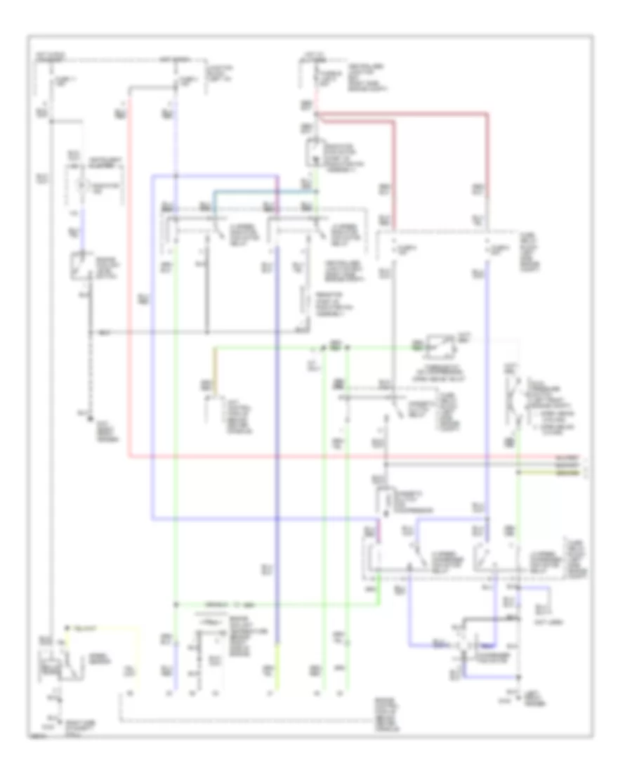
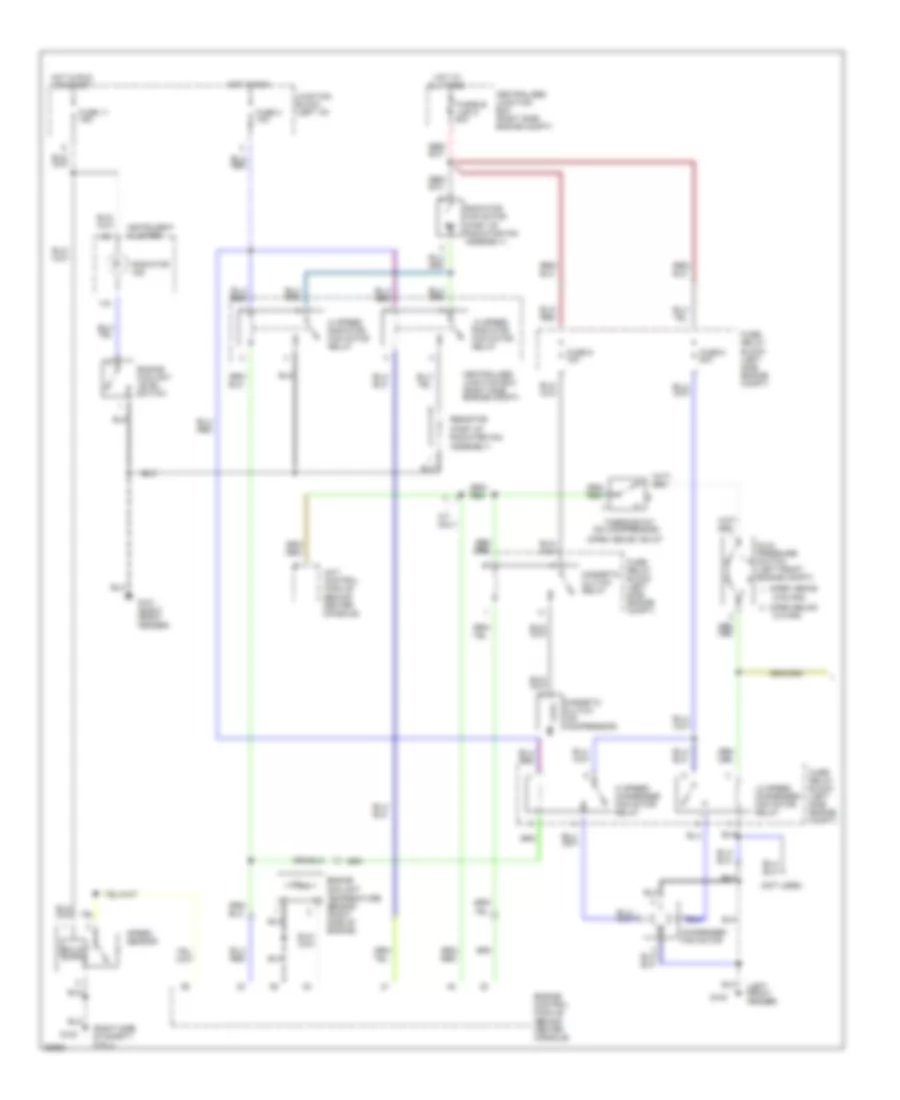
3.0L DOHC, Air Conditioning Wiring Diagrams (1 of 2) for Mitsubishi 3000GT 1997 3000
List of elements for 3.0L DOHC, Air Conditioning Wiring Diagrams (1 of 2) for Mitsubishi 3000GT 1997 3000:
- (left front fender)
- (not used)
- (on compressor)
- (open above
- (open above 155 c)
- (open below
- (part of radiator fan assembly)
- (right side of safety wall)
- 210 kpa)
- 2700 kpa)
- 4a/t control module (behind center console)
- A/t only
- All times
- Centralized junction box (right side engine compt)
- Condenser fan motor
- Dual pressure switch (left front engine compt)
- Engine control module (behind center console)
- Engine coolant level switch
- Engine coolant temperature sensor (right side of engine)
- Fuse 11 15a
- Fuse 3 10a
- Fuse 8 20a
- Fuse 9 10a
- Fuse/ relay block (left side engine compt)
- Fusible link 5 40a
- G100
- G101 (right front fender)
- G123
- Hi speed condenser fan motor relay
- Hi speed radiator fan motor relay
- Hot at
- Hot in run
- Hot in run or start
- Instrument cluster
- Junction block (left i/p)
- Lo speed condenser fan motor relay
- Lo speed radiator fan motor relay
- Magnetic clutch (on compressor)
- Magnetic clutch relay
- Radiator fan motor
- Radiator ind.
- Resistor
- Solid state
- Speed sensor
- Thermostat
3.0L DOHC, Air Conditioning Wiring Diagrams (2 of 2) for Mitsubishi 3000GT 1997 3000
List of elements for 3.0L DOHC, Air Conditioning Wiring Diagrams (2 of 2) for Mitsubishi 3000GT 1997 3000:
- (behind center
- (below glove box)
- (on compressor)
- (on evap-
- A/c compressor lock controller
- A/c control
- A/c switch
- Air
- Blower motor
- Blower motor relay
- Blower resistors
- Blower switch
- Console)
- Defroster switch
- Fuse 16 30a
- Fuse 3 10a
- G202 (left side of i/p)
- Hot at all times
- Hot in run
- Ignition power
- Illumination
- Ind.
- Interior lights system (rheostat)
- Interior lights system (taillight relay)
- Junction block (left i/p)
- Nca
- Off
- Orator)
- Red
- Revolution
- Rpm out
- Sensor
- Tacho- meter
- Thermo sensor
- Transistor
- Unit
3.0L SOHC, Air Conditioning Wiring Diagrams (1 of 2) for Mitsubishi 3000GT 1997 3000
List of elements for 3.0L SOHC, Air Conditioning Wiring Diagrams (1 of 2) for Mitsubishi 3000GT 1997 3000:
- (left front fender)
- (not used)
- (on compressor)
- (open above
- (open above 155 c)
- (open below
- (part of radiator fan assembly)
- (right side of safety wall)
- 210 kpa)
- 2700 kpa)
- 4a/t control module (behind center console)
- A/t only
- All times
- Centralized junction box (right side engine compt)
- Condenser fan motor
- Dual pressure switch (left front engine compt)
- Engine control module (behind center console)
- Engine coolant level switch
- Engine coolant temperature sensor (right side of engine)
- Fuse 11 15a
- Fuse 3 10a
- Fuse 8 20a
- Fuse 9 10a
- Fuse/ relay block (left side engine compt)
- Fusible link 5 40a
- G100
- G101 (right front fender)
- G123
- Hi speed condenser fan motor relay
- Hi speed radiator fan motor relay
- Hot at
- Hot in run
- Hot in run or start
- Instrument cluster
- Junction block (left i/p)
- Lo speed condenser fan motor relay
- Lo speed radiator fan motor relay
- Magnetic clutch (on compressor)
- Magnetic clutch relay
- Radiator fan motor
- Radiator ind.
- Resistor
- Solid state
- Speed sensor
- Thermostat
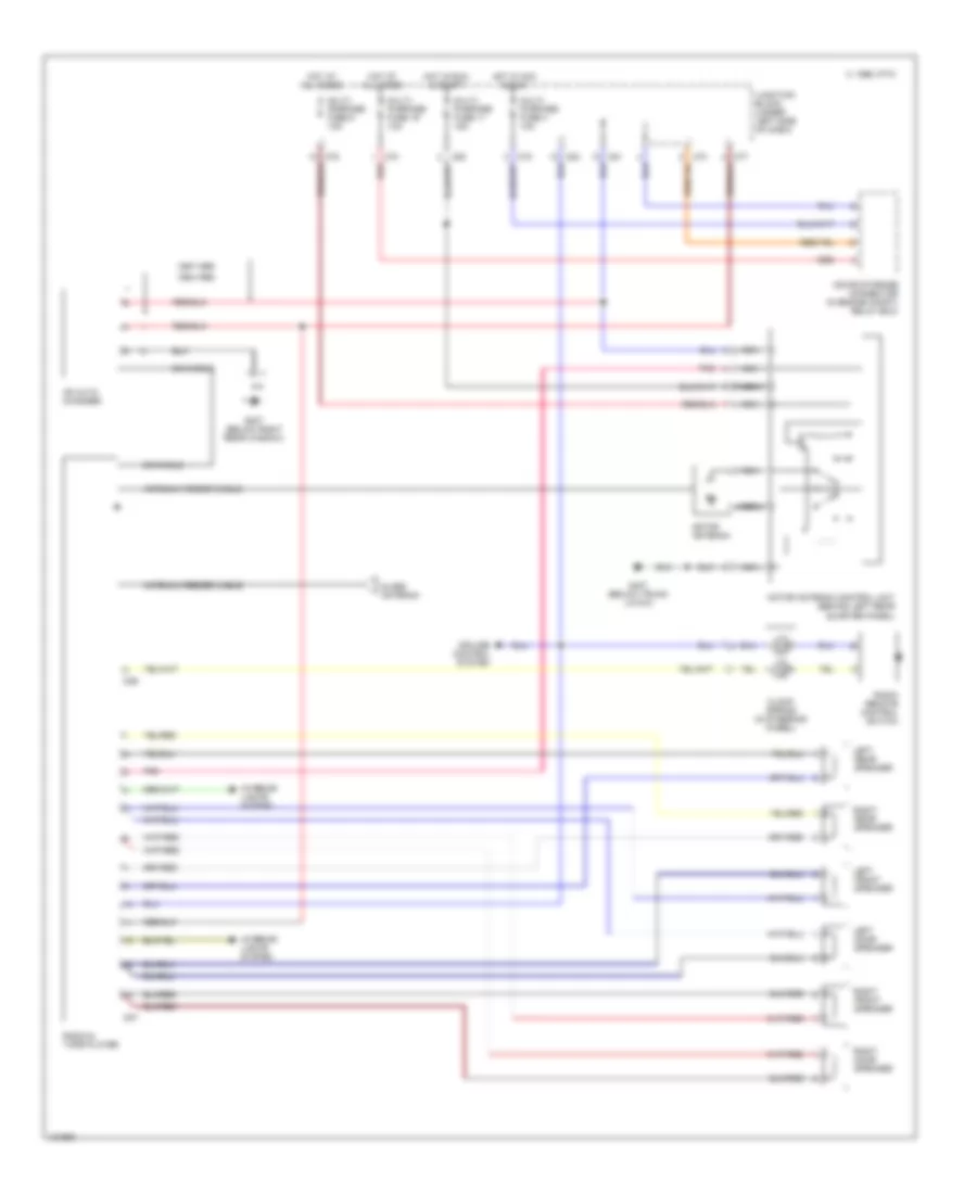
3.0L SOHC, Air Conditioning Wiring Diagrams (2 of 2) for Mitsubishi 3000GT 1997 3000
List of elements for 3.0L SOHC, Air Conditioning Wiring Diagrams (2 of 2) for Mitsubishi 3000GT 1997 3000:
- (behind center
- (on evap-
- A/c control
- A/c switch
- Air
- Blower motor
- Blower motor relay
- Blower resistors
- Blower switch
- Console)
- Defroster switch
- Fuse 16 30a
- Fuse 3 10a
- G202 (left side of i/p)
- Hot at all times
- Hot in run
- Illumination
- Ind.
- Interior lights system (rheostat)
- Interior lights system (taillight relay)
- Junction block (left i/p)
- Nca
- Off
- Orator)
- Red
- Thermo sensor
- Unit
ANTI-LOCK BRAKES
Anti-lock Brake Wiring Diagrams for Mitsubishi 3000GT 1997 3000
List of elements for Anti-lock Brake Wiring Diagrams for Mitsubishi 3000GT 1997 3000:
- (not used)
- (on each wheel hub assembly)
- (w/ awd)
- A64
- A65
- Abs control unit (behind right rear quarter
- Abs hydraulic unit (on right front of engine compt)
- Abs indicator
- Abs motor relay (on abs hydraulic unit)
- Abs valve relay (on abs hydraulic unit)
- C69
- C71
- C79
- C83
- Combination meter
- D04
- Data link connector 1 (partial) (right of steering column)
- Engine compartment relay box (on right side of engine compt, near shock tower)
- Fusible link 7 60a
- G sensor (w/ awd only) (under center console, near shift lever)
- G307 (below right rear window)
- Hot at all times
- Hot in on
- Hot in on or start
- Junction block (under left side of dash)
- Left front exhaust valve
- Left front intake valve
- Left front wheel speed sensor
- Left rear exhaust valve
- Left rear intake valve
- Left rear wheel speed sensor
- Multi- purpose fuse 11 15a
- Multi- purpose fuse 17 15a
- Multi- purpose fuse 3 10a
- Nca
- Panel)
- Pins 1-29 not used
- Pnk
- Pump motor
- Red
- Right front exhaust valve
- Right front intake valve
- Right front wheel speed sensor
- Right rear exhaust valve
- Right rear intake valve
- Right rear wheel speed sensor
- Stop- light switch (on bracket, above brake pedal)
ANTI-THEFT
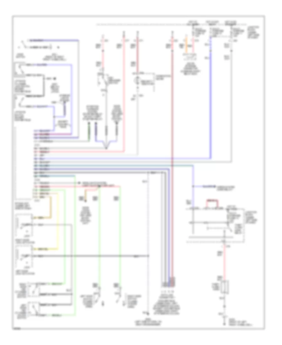
Anti-theft Wiring Diagram for Mitsubishi 3000GT 1997 3000
List of elements for Anti-theft Wiring Diagram for Mitsubishi 3000GT 1997 3000:
- (convertible: under dash, left of steering column) (except convertible: under dash, right of steering column)
- (except conver- tible)
- C101
- C102
- C70
- C71
- C76
- C77
- C78
- C80
- C81
- C83
- Combination meter
- D04
- Data link connector 1
- Deck crossmember)
- Door locks system (keyless entry control unit)
- Etacs unit (under left side of dash)
- G101 (front of right front wheelwell)
- G10o (front of left front wheelwell)
- G202 (left side of dash, on
- G407 (below trunk latch)
- Headlights system (light auto shut-off unit)
- Hood
- Horns system (horn relay)
- Hot at all times
- Hot in acc or on
- Hot in on or start
- Interior lights system
- Iod or storage connector (in engine compt relay box)
- Junction block (under left side of dash)
- Key reminder switch
- Left door
- Left door key cylinder unlock switch
- Left door lock actuator
- Liftgate cylinder lock switch (except convertible)
- Liftgate switch (except convertible)
- Lock
- Multi- purpose fuse 10 15a
- Multi- purpose fuse 11 15a
- Multi- purpose fuse 14 10a
- Multi- purpose fuse 19 10a
- Nca
- Red
- Right door
- Right door key cylinder unlock switch
- Right door lock actuator
- Security indicator
- Starting/ charging system (starter relay or anti-theft starter relay)
- Switch
- Switch (closed w/door open)
- Theft alarm horn
- Theft alarm horn relay
- Unlock
BODY COMPUTER
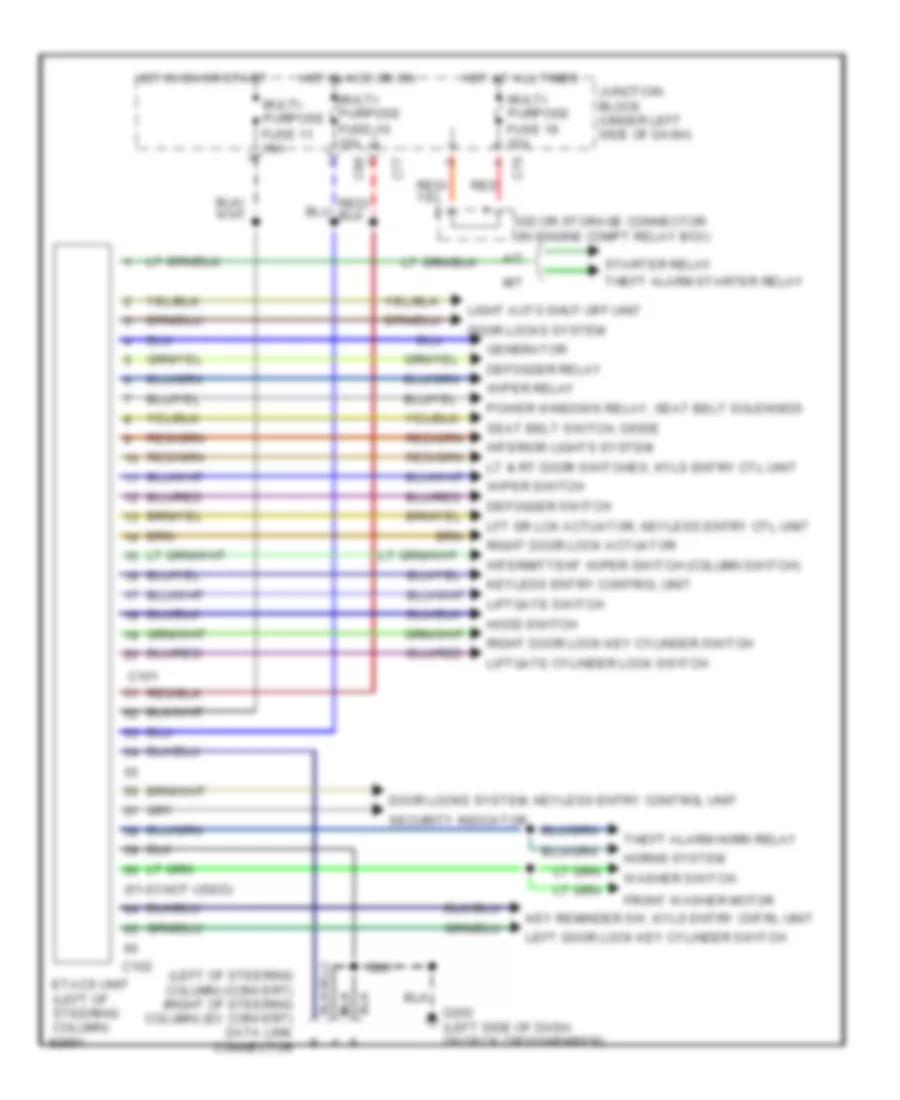
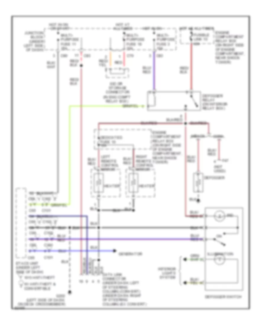
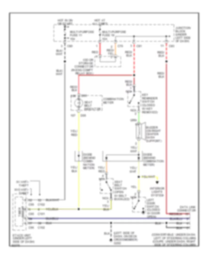
Body Computer Wiring Diagrams, with Anti-theft for Mitsubishi 3000GT 1997 3000
List of elements for Body Computer Wiring Diagrams, with Anti-theft for Mitsubishi 3000GT 1997 3000:
- (61-63 not used)
- (left of steering column) (convert) (right of steering column) (ex convert) data link connector
- A/t
- C101
- C102
- C70
- C77
- C80
- Defogger relay
- Defogger switch
- Door locks system
- Door locks system, keyless entry control unit
- Etacs unit (left of steering column)
- Front washer motor
- G202 (left side of dash. on deck crossmember)
- Generator
- Hood switch
- Horns system
- Hot at all times
- Hot in acc or on
- Hot in on or start
- Interior lights system
- Intermittent wiper switch (column switch)
- Iod or storage connector (in engine compt relay box)
- Junction block (under left side of dash)
- Key reminder sw, kyls entry cntrl unit
- Keyless entry control unit
- Left door lock key cylinder switch
- Lft dr lck actuator, keyless entry ctl unit
- Liftgate cylinder lock switch
- Liftgate switch
- Light auto shut-off unit
- Lt & rt door switches, kyls entry ctl unit
- M/t
- Multi- purpose fuse 10 15a
- Multi- purpose fuse 11 15a
- Multi- purpose fuse 19 10a
- Power windows relay, seat belt solenoids
- Red
- Right door lock actuator
- Right door lock key cylinder switch
- Seat belt switch, diode
- Security indicator
- Starter relay
- Theft alarm horn relay
- Theft alarm starter relay
- Washer switch
- Wiper relay
- Wiper switch
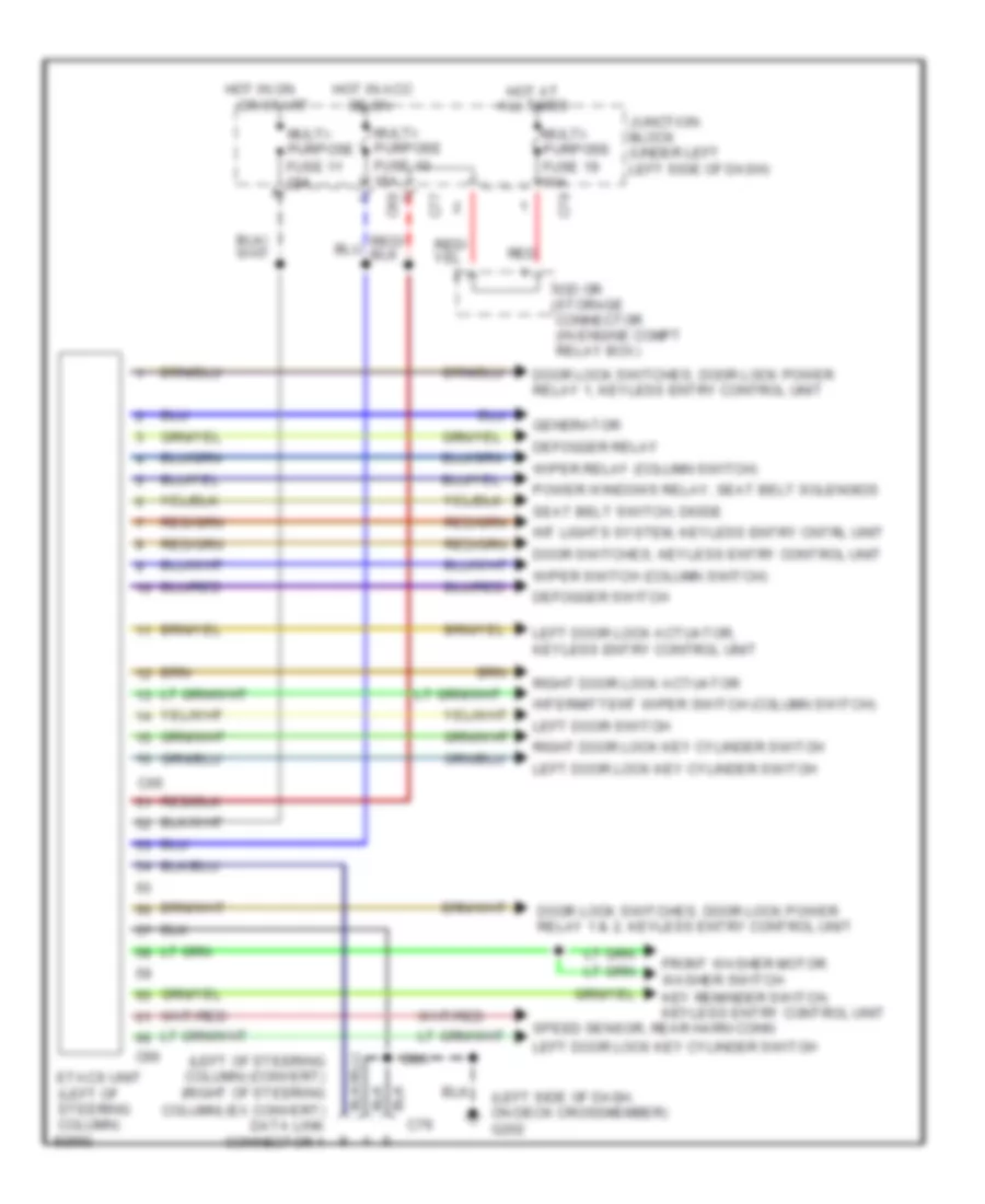
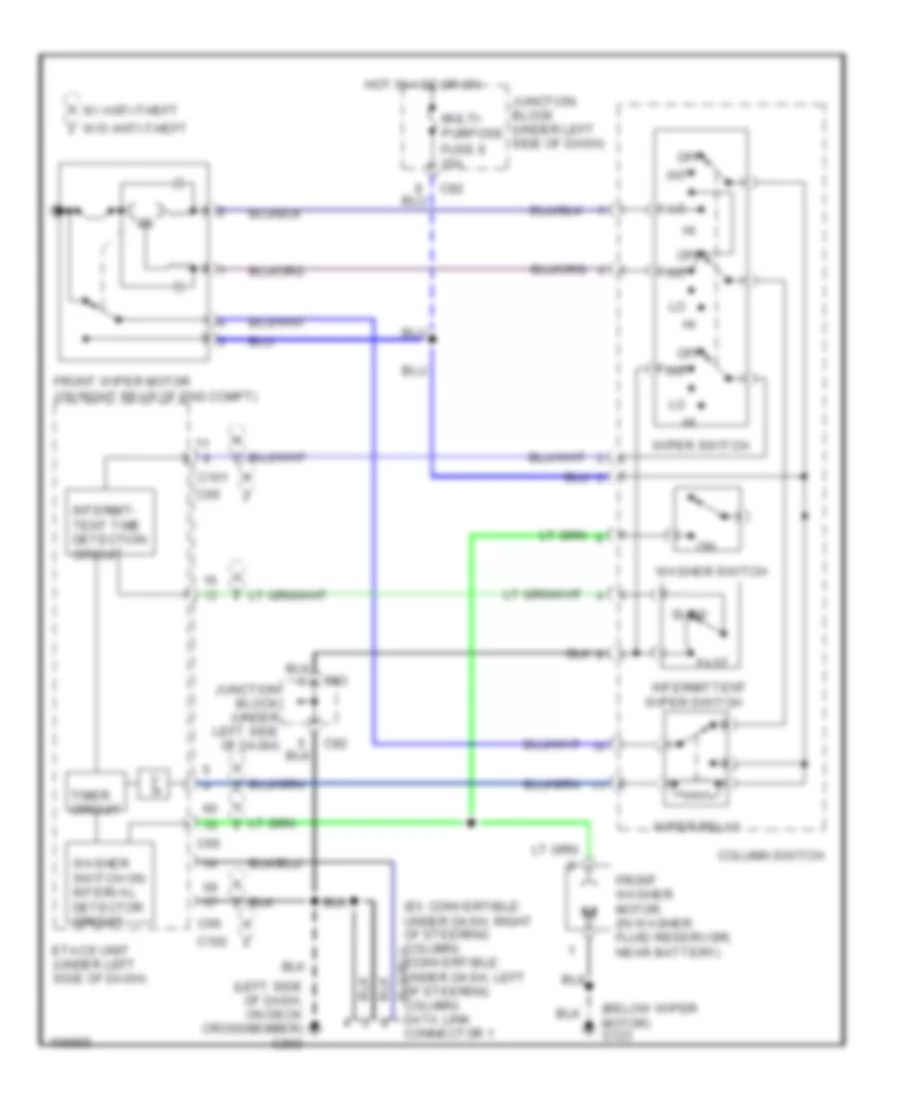
Body Computer Wiring Diagrams, without Anti-theft for Mitsubishi 3000GT 1997 3000
List of elements for Body Computer Wiring Diagrams, without Anti-theft for Mitsubishi 3000GT 1997 3000:
- (left of steering column) (convert) (right of steering
- (left side of dash, on deck crossmember) g202
- C65
- C66
- C70
- C77
- C79
- C80
- Defogger relay
- Defogger switch
- Door lock switches, door lock power relay 1 & 2, keyless entry control unit
- Door lock switches, door lock power relay 1, keyless entry control unit
- Door switches, keyless entry control unit
- Etacs unit (left of steering column)
- Front washer motor washer switch
- Generator
- Hot at all times
- Hot in acc
- Hot in on
- Int lights system, keyless entry cntrl unit
- Intermittent wiper switch (column switch)
- Iod or storage connector (in engine compt relay box)
- Junction block (under left left side of dash)
- Key reminder switch, keyless entry control unit
- Left door lock actuator, keyless entry control unit
- Left door lock key cylinder switch
- Left door switch
- Multi- purpose fuse 10 15a
- Multi- purpose fuse 11 15a
- Multi- purpose fuse 19 10a
- Or on
- Or start
- Power windows relay, seat belt solenoids
- Red
- Right door lock actuator
- Right door lock key cylinder switch
- Seat belt switch, diode
- Speed sensor, rear harn conn
- Wiper relay (column switch)
- Wiper switch (column switch)
COMPUTER DATA LINES
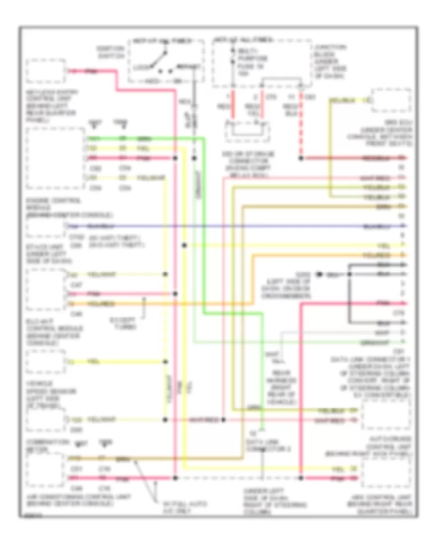
Computer Data Lines for Mitsubishi 3000GT 1997 3000
List of elements for Computer Data Lines for Mitsubishi 3000GT 1997 3000:
- (under left side of dash, right of steering column)
- (w/ anti theft) (w/o anti theft)
- Abs control unit (behind right rear quarter panel)
- Acc
- Air conditioning control unit (behind center console)
- Auto-cruise control unit (behind right kick panel)
- C102
- C16
- C46
- C47
- C49
- C51
- C54
- C66
- C70
- C79
- C83
- C91
- C92
- Combination meter
- D05
- Data link connector 1 (under dash, left of steering column- convert, right of of steering column- ex convertible)
- Data link connector 2
- Elc-4a/t control module (behind center console)
- Engine control module (behind center console)
- Etacs unit (under left side of dash)
- Except turbo
- G202 (left side of dash, on deck crossmember)
- Hot at all times
- Ignition switch
- Iod or storage connector (in eng compt relay box)
- Junction block (under left side of dash)
- Keyless entry control unit (behind left rear quarter panel)
- Lock
- Multi- purpose fuse 19 10a
- N/a
- Nca
- Pnk
- Rear harness (right rear of vehicle)
- Red
- Srs ecu (under center console, between front seats)
- Start
- Vehicle speed sensor (left side of trans)
- W/ full auto a/c only
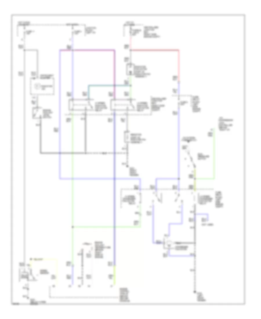
COOLING FAN
Cooling Fan Wiring Diagram for Mitsubishi 3000GT 1997 3000
List of elements for Cooling Fan Wiring Diagram for Mitsubishi 3000GT 1997 3000:
- (behind
- (not used)
- (part of radiator fan assembly)
- A/c
- A/c system (thermostat)
- All times
- Centralized junction box (right side engine compt)
- Compressor
- Condenser fan motor
- Controller
- Dual pressure switch
- Engine control module (behind center console)
- Engine coolant level switch
- Engine coolant temperature sensor (right side of engine)
- Fuse 11 15a
- Fuse 3 10a
- Fuse 8 20a
- Fuse/ relay block (left side engine compt)
- Fusible link 5 40a
- G100 (left front fender)
- G101 (right front fender)
- G123 (below wiper motor)
- Hi speed
- Hi speed radiator fan motor relay
- Hot at
- Hot in run
- Hot in run or start
- Instrument cluster
- Junction block (left i/p)
- Lo speed condenser fan motor relay
- Lo speed radiator fan motor relay
- Lock
- Radiator fan motor
- Radiator ind.
- Relay
- Resistor
- Right i/p)
- Solid state
- Speed sensor
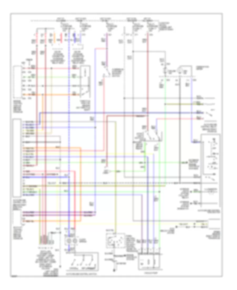
CRUISE CONTROL
Cruise Control Wiring Diagram, A/T for Mitsubishi 3000GT 1997 3000
List of elements for Cruise Control Wiring Diagram, A/T for Mitsubishi 3000GT 1997 3000:
- (behind front console)
- (behind right side kick panel)
- (in engine compartment relay box)
- (not used)
- 1998-99
- Asc ind
- Auto-cruise control main switch
- Auto-cruise control relay
- Auto-cruise control switch
- Auto-cruise control unit
- C46
- C47
- C52
- C54
- C70
- C71
- C77
- C81
- C83
- Cancel
- Clock spring
- Combination meter
- Connector
- Cruise ind
- D04
- D05
- Data link connector (convert: under dash, left of steering column) (ex convert: under dash, right of steering column)
- Elc-4 a/t control module (behind center console)
- Engine control module (behind center console)
- Engine controls system
- Exterior lights & engine controls systems
- G123 (below wiper motor)
- G202 (left side of dash, on deck crossmember)
- Hot at all times
- Hot in acc
- Hot in on or start
- Illumination
- Interior lights system (rheostat)
- Interior lights system (taillight relay)
- Iod or storage
- Junction block (under left side of dash)
- Multi- purpose fuse 11 15a
- Multi- purpose fuse 17 15a
- Multi- purpose fuse 19 10a
- Multi- purpose fuse 4 10a
- Multi- purpose fuse 7 10a
- Nca
- Off
- Or on
- Overdrive & power/ economy switch
- Park/ neutral position switch (on shift control lever, on transaxle)
- Red
- Resume
- Set
- Speed sensor (right side of transaxle)
- Starter
- Stop- light switch (on bracket, above brake pedal)
- Throttle position sensor (on throttle body)
- Vacuum pump
Cruise Control Wiring Diagram, M/T for Mitsubishi 3000GT 1997 3000
List of elements for Cruise Control Wiring Diagram, M/T for Mitsubishi 3000GT 1997 3000:
- (behind front console)
- (behind right side kick panel)
- (in eng compt relay box)
- (not used)
- 1998-99
- Asc indicator
- Auto-cruise control main switch
- Auto-cruise control relay
- Auto-cruise control switch
- Auto-cruise control unit
- C52
- C54
- C63
- C70
- C71
- C77
- C83
- Cancel
- Clock spring
- Clutch pedal position switch (behind dash, on clutch pedal bracket)
- Combination meter
- Connector
- Cruise indicator
- D04
- D05
- Data link connector 1 (under dash, left dash, left of steering column) (ex convert: under dash, right of steering column)
- Engine control module (behind center console)
- Exterior lights & engine controls systems
- G123 (below wiper motor)
- G202 (left side of dash, on deck crossmember)
- Hot at all times
- Hot in acc or run
- Hot in on or start
- Illumination
- Interior lights system (rheostat)
- Interior lights system (taillight relay)
- Iod or storage
- Junction block (under left side of dash)
- Multi- purpose fuse 11 15a
- Multi- purpose fuse 17 15a
- Multi- purpose fuse 19 10a
- Multi- purpose fuse 4 10a
- Nca
- Off
- Red
- Resume
- Set
- Speed sensor (right side of transaxle)
- Stop- light switch (on bracket, above brake pedal)
- Throttle position sensor (on throttle body)
- Vacuum pump
DEFOGGERS
Defogger Wiring Diagram for Mitsubishi 3000GT 1997 3000
List of elements for Defogger Wiring Diagram for Mitsubishi 3000GT 1997 3000:
- (in eng compt relay box)
- (not used)
- C101
- C102
- C65
- C66
- C70
- C80
- C83
- Connector
- Conv
- Data link connector (under dash, left of steering column) (convert) (under dash, right of steering column) (ex convert)
- Dedicated fuse 10 10a
- Defogger
- Defogger relay (on interior relay box)
- Defogger switch
- Engine compartment relay box (on right side of engine compartment, near shock tower)
- Etacs unit (under left side of dash)
- F47
- Fusible link 10 40a
- G202 (left side of dash, on deck crossmember)
- Generator
- H/back
- Heater
- Hot at all times
- Hot in on
- Hot in on or start
- Illumination
- Ind
- Interior lights system
- Iod or storage
- Junction block (under left side of dash)
- Left remote control mirror
- Multi- purpose fuse 11 15a
- Multi- purpose fuse 19 10a
- Multi- purpose fuse 3 10a
- Red
- Right remote control mirror
- W/ anti-theft & convertible
- W/o anti-theft
ENGINE PERFORMANCE
3.0L
3.0L DOHC Non-Turbo, Engine Performance Wiring Diagrams (1 of 3) for Mitsubishi 3000GT 1997 3000
List of elements for 3.0L DOHC Non-Turbo, Engine Performance Wiring Diagrams (1 of 3) for Mitsubishi 3000GT 1997 3000:
- (center of i/p, right of center console) mfi relay i
- (center of i/p, right of center console) mfi relay ii
- (left side of engine)
- B21
- B22
- C46
- C47
- C52
- C53
- Capacitor (right front of engine)
- Check engine indicator (mil)
- Clutch relay
- Combination meter
- Dedicated fuse 1 20a
- Elc-4 a/t control unit (behind center console)
- Engine speed detection connector (right side of safety wall)
- Fuel injectors
- G123 (right side of safety wall)
- G206 (behind right side of center console)
- Hot at all times
- Ignition coil 1-4 (top of engine)
- Ignition coil 2-5 (top of engine)
- Ignition coil 3-6 (top of engine)
- Ignition power transistor (top of engine)
- Magnetic
- Nca
- Power
- Powertrain control module (behind center console)
- Radiator & condenser fan motor relays
- Red
- Spark plugs 1 & 4
- Spark plugs 2 & 5
- Spark plugs 3 & 6
- Steering pressure
- Switch
- Tach
- Thermostat
- Under- hood fuse block
3.0L DOHC Non-Turbo, Engine Performance Wiring Diagrams (2 of 3) for Mitsubishi 3000GT 1997 3000
List of elements for 3.0L DOHC Non-Turbo, Engine Performance Wiring Diagrams (2 of 3) for Mitsubishi 3000GT 1997 3000:
- (right side of engine, below throttle body) isc motor
- A/t
- A/t w/ theft alarm
- A/t w/ theft alarm & m/t
- A/t w/o theft alarm
- Acc
- Auto-cruise control unit
- B10
- C71
- C82
- Charging system
- Egr solenoid valve (right rear of safety wall)
- Evaporative emission purge solenoid (right rear of safety wall)
- Fuel pump
- Fuel pump check connector (right side of safety wall)
- G206 (behind right side of center console)
- G407 (center rear of trunk, on latch)
- Hot at all times
- Ig1
- Ig2
- Ignition switch
- Junction block (left side of i/p)
- Lock
- M/t
- Manifold differential pressure sensor (right rear of engine)
- Multi- purpose fuse 11 15a
- Multi- purpose fuse 12 15a
- Nca
- Park/neutral position switch (top of transmission)
- Red
- Run
- Start
- Starter relay (in underhood fuse block)
- Starting system
- Variable induction control motor (left front side of engine)
3.0L DOHC Non-Turbo, Engine Performance Wiring Diagrams (3 of 3) for Mitsubishi 3000GT 1997 3000
List of elements for 3.0L DOHC Non-Turbo, Engine Performance Wiring Diagrams (3 of 3) for Mitsubishi 3000GT 1997 3000:
- (after catalytic converter)
- (before catalytic converter)
- (right side of
- A/c control unit
- A/t
- Adjustment connector
- Atmospheric press sensor
- Auto-cruise control unit (behind right kick panel)
- C54
- C69
- C70
- C77
- C83
- C92
- Ckp sensor (on vibration damper)
- Cmp sensor (left side of engine)
- Combination meter (speedometer)
- Data link connector (partial) (below left side of i/p)
- Dedicated fuse 2 15a
- Defogger relay
- Diode
- Elc-4 a/t control module
- Engine coolant temperature sensor (near thermostat assembly)
- G123 (right side of safety wall)
- G202 (left side of i/p)
- Heated oxygen sensor (front)
- Hot at all times
- Ignition timing
- Intake air temp sensor
- Iod or storage connector
- Junction block
- Knock sensor (on cylinder head, near intake manifold)
- Left bank heated oxygen sensor (front)
- Left bank heated oxygen sensor (rear)
- Multi- purpose fuse 19 10a
- Nca
- Pnk
- Powertrain control module (behind center console)
- Red
- Right bank
- Right bank heated oxygen sensor (rear)
- Safety wall)
- Speed sensor (on transmission)
- Stop light switch
- Taillight relay
- Throttle position sensor (on throttle body)
- Under- hood fuse block
- Volume air flow sensor (on air cleaner assembly)
- W/ auto a/c only
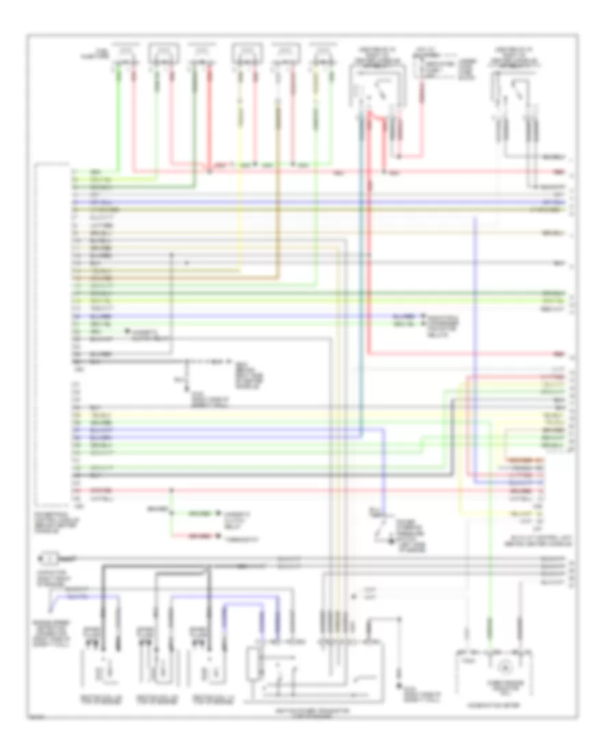
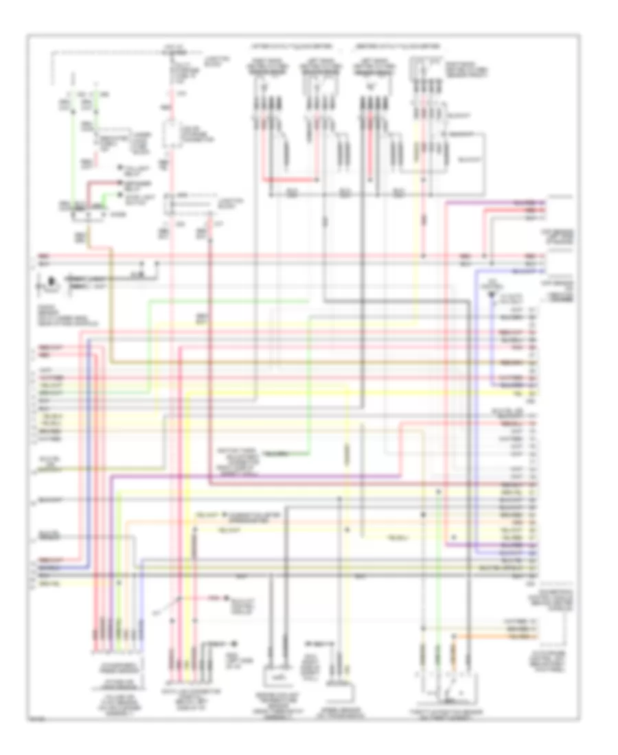
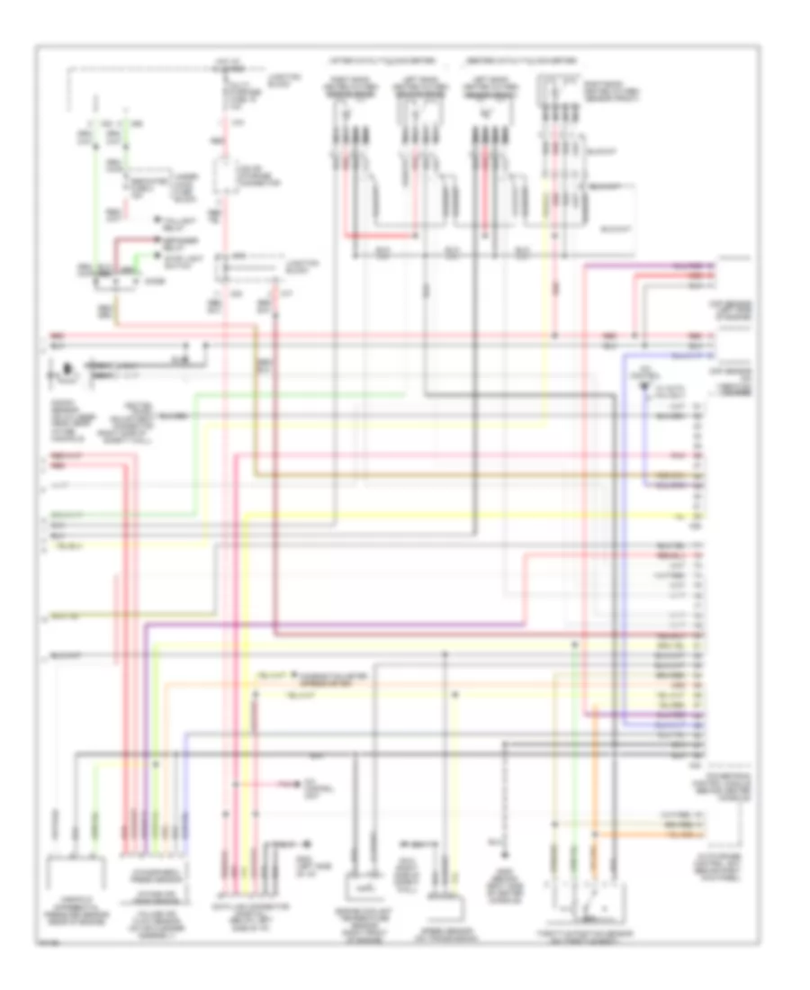
3.0L DOHC Turbo, Engine Performance Wiring Diagrams (1 of 3) for Mitsubishi 3000GT 1997 3000
List of elements for 3.0L DOHC Turbo, Engine Performance Wiring Diagrams (1 of 3) for Mitsubishi 3000GT 1997 3000:
- (center of i/p, right of center console) mfi relay i
- (center of i/p, right of center console) mfi relay ii
- (left side of engine)
- B21
- B22
- C52
- C53
- Capacitor (right front of engine)
- Check engine indicator (mil)
- Clutch relay
- Combination meter
- Dedicated fuse 1 20a
- Engine speed detection connector (right side of safety wall)
- Fuel
- G123 (right side of safety wall)
- G206 (behind right side of center console)
- Hot at all times
- Ignition coil 1-4 (top of engine)
- Ignition coil 2-5 (top of engine)
- Ignition coil 3-6 (top of engine)
- Ignition power transistor (top of engine)
- Injectors
- Magnetic
- Nca
- Power
- Powertrain control module (behind center console)
- Radiator & condenser fan motor relays
- Red
- Resistor (right rear of engine compt)
- Spark plugs 1 & 4
- Spark plugs 2 & 5
- Spark plugs 3 & 6
- Steering pressure
- Switch
- Tach
- Under- hood fuse block
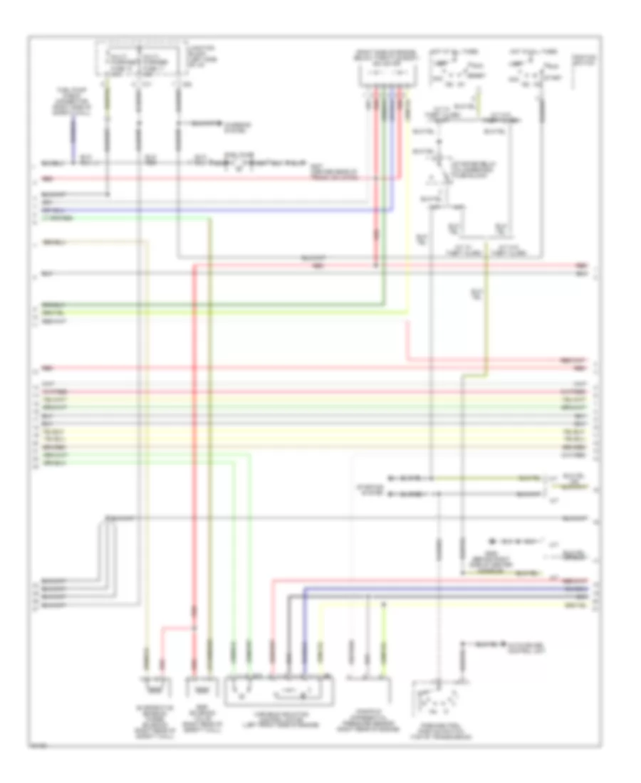
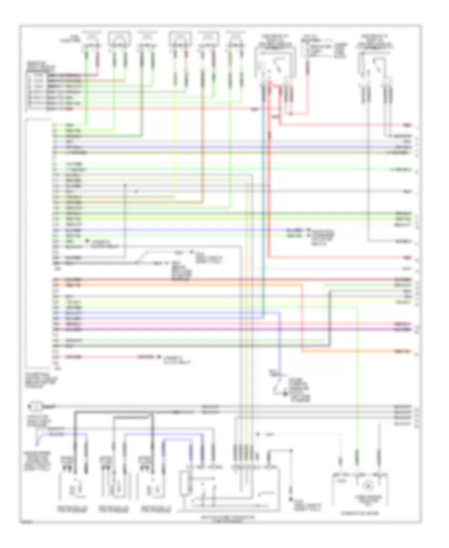
3.0L DOHC Turbo, Engine Performance Wiring Diagrams (2 of 3) for Mitsubishi 3000GT 1997 3000
List of elements for 3.0L DOHC Turbo, Engine Performance Wiring Diagrams (2 of 3) for Mitsubishi 3000GT 1997 3000:
- (right side of engine, below throttle body) isc motor
- Acc
- Boost gauge
- C71
- C82
- Charging system
- Egr solenoid valve (right side of safety wall)
- Evaporative emission purge solenoid (right side of safety wall)
- Fuel pressure solenoid (right side of safety wall)
- Fuel pump
- Fuel pump check connector (right side of safety wall)
- Fuel pump circuit resistor (right side of engine compartment)
- Fuel pump relay (near underhood relay box)
- G206 (behind right side of center console)
- Gauge assembly
- Hot at all times
- Ig1
- Ig2
- Ignition switch
- Junction block (left side of i/p)
- Lock
- Multi- purpose fuse 11 15a
- Multi- purpose fuse 12 15a
- Nca
- Red
- Run
- Start
- Starter relay (in underhood fuse block)
- Starting
- System
- Turbocharger waste gate solenoid (right side of safety wall)
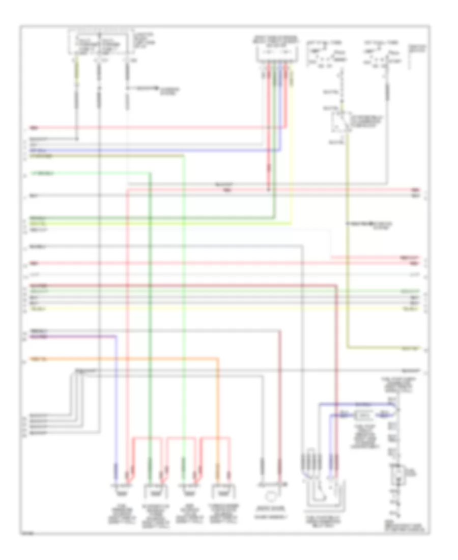
3.0L DOHC Turbo, Engine Performance Wiring Diagrams (3 of 3) for Mitsubishi 3000GT 1997 3000
List of elements for 3.0L DOHC Turbo, Engine Performance Wiring Diagrams (3 of 3) for Mitsubishi 3000GT 1997 3000:
- (after catalytic converter)
- (before catalytic converter)
- (right side of
- A/c control unit
- Adjustment connector
- Atmospheric press sensor
- Auto-cruise control unit (behind right kick panel)
- C54
- C69
- C70
- C77
- C83
- C92
- Ckp sensor (on vibration damper)
- Cmp sensor (left side of engine)
- Combination meter (speedometer)
- Data link connector (partial) (below left side of i/p)
- Dedicated fuse 2 15a
- Defogger relay
- Diode
- Engine coolant temperature sensor (right front of engine)
- G123 (right side of safety wall)
- G202 (left side of i/p)
- G206 (behind right side of center console)
- Heated oxygen sensor (front)
- Hot at all times
- Ignition
- Intake air temp sensor
- Iod or storage connector
- Junction block
- Knock sensor (on cylinder head, near intake manifold)
- Left bank heated oxygen sensor (front)
- Left bank heated oxygen sensor (rear)
- Manifold differential pressure sensor (rear of engine)
- Multi- purpose fuse 19 10a
- Nca
- Pnk
- Powertrain control module (behind center console)
- Red
- Right bank
- Right bank heated oxygen sensor (rear)
- Safety wall)
- Speed sensor (on transmission)
- Stop light switch
- Taillight relay
- Throttle position sensor (on throttle body)
- Timing
- Under- hood fuse block
- Volume air flow sensor (on air cleaner assembly)
- W/ auto a/c only
3.0L SOHC, Engine Performance Wiring Diagrams (1 of 3) for Mitsubishi 3000GT 1997 3000
List of elements for 3.0L SOHC, Engine Performance Wiring Diagrams (1 of 3) for Mitsubishi 3000GT 1997 3000:
- (center of i/p, right of center console) mfi relay i
- (center of i/p, right of center console) mfi relay ii
- (left side of engine)
- C46
- C47
- C52
- C53
- Check engine indicator (mil)
- Clutch relay
- Coil wire
- Combination meter
- Condenser
- Condenser assembly
- Dedicated fuse 1 20a
- Distributor (top left side of engine)
- Elc-4 a/t control unit (behind center console)
- Fuel injectors
- G123 (right side of safety wall)
- G203 (right kick panel)
- G206 (behind right side of center console)
- Hot at all times
- Ignition coil (left side of intake manifold)
- Ignition power transistor (left side of intake manifold)
- Magnetic
- Noise filter
- Power
- Powertrain control module (behind center console)
- Radiator & condenser fan motor relays
- Red
- Spark plugs
- Steering pressure
- Switch
- Tach
- Thermostat
- Under- hood fuse block
3.0L SOHC, Engine Performance Wiring Diagrams (2 of 3) for Mitsubishi 3000GT 1997 3000
List of elements for 3.0L SOHC, Engine Performance Wiring Diagrams (2 of 3) for Mitsubishi 3000GT 1997 3000:
- (right side of engine, below throttle body) isc motor
- A/t
- A/t w/ theft alarm
- A/t w/ theft alarm & m/t
- A/t w/o theft alarm
- Acc
- Auto-cruise control unit
- C71
- C82
- Charging system
- Egr solenoid valve (right rear of safety wall)
- Evaporative emission purge solenoid (right rear of safety wall)
- Fuel pump
- Fuel pump check connector (right side of safety wall)
- G206 (behind right side of center console)
- G407 (center rear of trunk, on latch)
- Hot at all times
- Ig1
- Ig2
- Ignition switch
- Junction block (left side of i/p)
- Lock
- M/t
- Manifold differential pressure sensor (right rear of engine)
- Multi- purpose fuse 11 15a
- Multi- purpose fuse 12 15a
- Nca
- Park/neutral position switch (top of transmission)
- Red
- Run
- Start
- Starter relay (in underhood fuse block)
- Starting system
3.0L SOHC, Engine Performance Wiring Diagrams (3 of 3) for Mitsubishi 3000GT 1997 3000
List of elements for 3.0L SOHC, Engine Performance Wiring Diagrams (3 of 3) for Mitsubishi 3000GT 1997 3000:
- (after catalytic converter)
- (before catalytic converter)
- (right side of
- A/c control unit
- A/t
- Adjustment connector
- Atmospheric press sensor
- Auto-cruise control unit (behind right kick panel)
- C54
- C70
- C77
- C83
- C92
- Ckp sensor (on vibration damper)
- Cmp sensor (inside distributor assembly)
- Combination meter (speedometer)
- Data link connector (partial) (below left side of i/p)
- Elc-4 a/t control module
- Engine coolant temperature sensor (near thermostat assembly)
- G123 (right side of safety wall)
- G202 (left side of i/p)
- Heated oxygen sensor (front)
- Hot at all times
- Ignition timing
- Intake air temp sensor
- Iod or storage connector
- Junction block
- Knock sensor (on cylinder head, near intake manifold)
- Left bank heated oxygen sensor (front)
- Left bank heated oxygen sensor (rear)
- Multi- purpose fuse 19 10a
- Nca
- Pnk
- Powertrain control module (behind center console)
- Red
- Right bank
- Right bank heated oxygen sensor (rear)
- Safety wall)
- Speed sensor (on transmission)
- Throttle position sensor (on throttle body)
- Volume air flow sensor (on air cleaner assembly)
- W/ auto a/c only
EXTERIOR LIGHTS
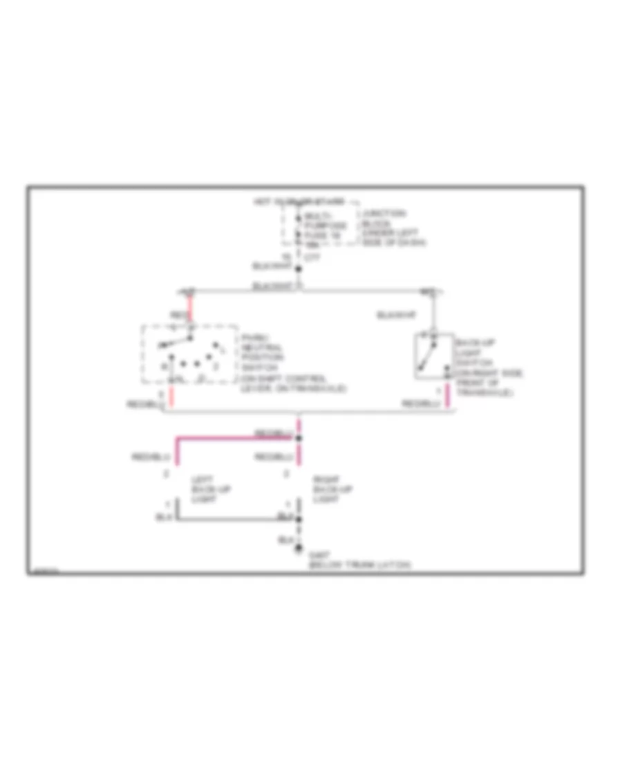
Back-up Lamps Wiring Diagram for Mitsubishi 3000GT 1997 3000
List of elements for Back-up Lamps Wiring Diagram for Mitsubishi 3000GT 1997 3000:
- (on shift control lever, on transaxle)
- A/t
- Back-up light switch (on right side, front of transaxle)
- C77
- G407 (below trunk latch)
- Hot in on or start
- Junction block (under left side of dash)
- Left back-up light
- M/t
- Multi- purpose fuse 18 10a
- Park/ neutral position switch
- Red
- Right back-up light
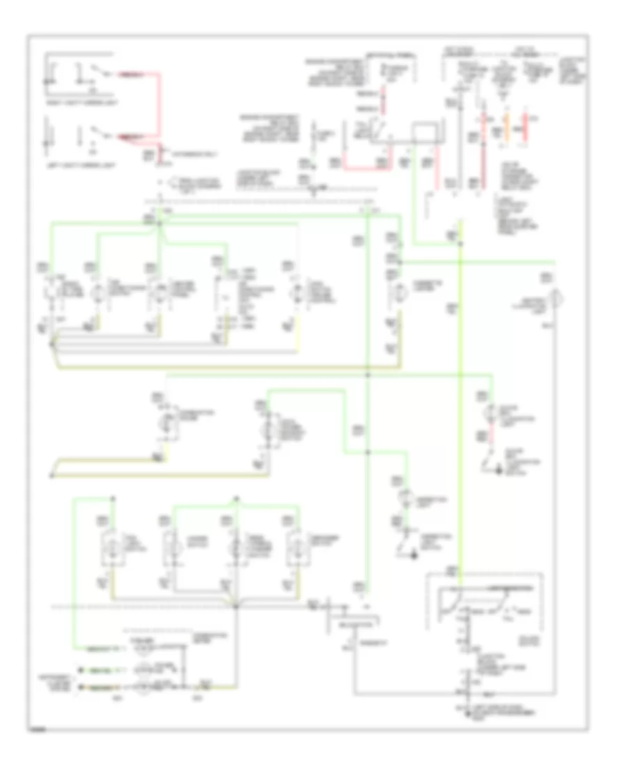
Exterior Lamps Wiring Diagram for Mitsubishi 3000GT 1997 3000
List of elements for Exterior Lamps Wiring Diagram for Mitsubishi 3000GT 1997 3000:
- (front of right front wheelwell) g101
- (hatch w/ cruise or convert) (hatch w/o cruise)
- (left side of dash, on deck crossmember) g202
- (left side of trunk lid) g406
- Abs
- All times
- C69
- C70
- C71
- C77
- C78
- C81
- C82
- C83
- Column switch (light switch)
- Column switch (turn- signal switch)
- Combination meter
- Control system
- Conv
- Cruise
- D04
- D05
- Dash, on deck crossmember)
- Dedicated fuse 2 15a
- Dedicated fuse 6 10a
- Engine compartment relay box (on right side of engine compt, near shock tower)
- Fusible link 3 40a
- G100 (front of left front wheelwell)
- G202 (left side of
- G202 (left side of dash, on deck crossmember)
- G301 (right front floor crossmember)
- G406 (left side of trunk lid)
- G407 (below trunk latch)
- Hatch
- Hatch only
- Hazard
- Hazard switch
- Head
- High mounted stop light (hatch only)
- Hot at
- Hot at all times
- Hot in on or start
- Interior lights system
- Iod or storage connector (in engine compt relay box)
- Junction block (under left side of dash)
- Left door switch
- Left front combin- ation light
- Left rear combination light
- Left turn ind
- License plate lights
- Light automatic shut-off unit (behind left rear quarter panel)
- Multi- purpose fuse 11 15a
- Multi- purpose fuse 17 15a
- Multi- purpose fuse 18 10a
- Multi- purpose fuse 19 10a
- Nca
- Off
- Red
- Rheostat
- Right front combination light
- Right rear combination light
- Right turn ind
- Solid state
- Stop light switch
- System
- Tail
- Tail- light relay
- Turn signal and hazard flasher unit (behind left kick panel)
GROUND DISTRIBUTION
Ground Distribution Wiring Diagram for Mitsubishi 3000GT 1997 3000
List of elements for Ground Distribution Wiring Diagram for Mitsubishi 3000GT 1997 3000:
- (a/t-right rear of
- (m/t-right rear of
- Abs control unit, cd auto changer (hatch w/ radio amplifier)
- Battery
- Condenser fan motor, condenser fan motor relay (lo), brake fluid level sensor, fog lights, left front combination lights, theft-alarm horn
- Data link connector 1, door lock switches, door lock actuators, door lock key cylinder switches, power window main switch, etacs unit, door lock power relay 1, key reminder switch, blower motor relay, blower switch, air conditioning compressor lock controller, air conditioning control unit, column switch, rear wiper & washer switch, remote controlled mirror switch, remote controlled mirrors (heaters), header harness (conv) srs ecu auto-cruise control unit, clutch pedal position switch (m/t), auto-cruise control main switch, combination meter power seat switch, power seat assembly, motor antenna control unit (conv) chime harness (conv), theft-alarm starter relay, rheostat, turn signal & hazard flasher unit, cigarette lighter, defogger switch combination gauge, accessory socket, ashtray illumination light, a/c power trnasistor, air conditioning switch, headlights (lo)
- Engine compt, on top of transaxle)
- Engine control module shield
- Engine control module, knock sensor, knock sensor shield, fuel pump (turbo), pulse generator a/b shield, elc-4 a/t control module, ignition power transistor, speed sensor, washer fluid level sensor, front washer motor, noise filter shield, cmp sensor, ckp sensor
- Engine, on transaxle stud)
- Fuel pump (non-turbo), door lock power relay 2, keyless entry control unit, fuel tank differential pressure sensor (1998) rear washer motor, back up lights fuel gauge unit, rear combination lights (conv), license plate lights, motor antenna control unit (hatch), liftgate cylinder lock switch (hatch), liftgate switch (hatch)
- G100 (front of left front wheelwell)
- G101 (front of right front wheelwell)
- G117 (m/t)
- G123 (below wiper motor)
- G129 (a/t)
- G134 (on intake manifold plenum)
- G202 (left side of dash, on deck crossmember)
- G206 (right center- reinforcement bracket)
- G300 (left front floor crossmember)
- G301 (right front floor crossmember)
- G307 (below right rear window)
- G406 (left side of trunk lid)
- G407 (below trunk latch)
- Radiator fan assembly, radiator fan motor relay (hi), abs hydraulic unit, right front combination light, horns, hood switch resistor (radiator fan assembly) engine coolant level sensor
- Rear harness (conv), cd auto changer (hatch w/o radio amplifier)
- Right rear combination light (hatch)
- Sunroof control unit, sunroof switch, sunroof motor, high mounted stop light, left rear combination light (hatch)
HEADLIGHTS
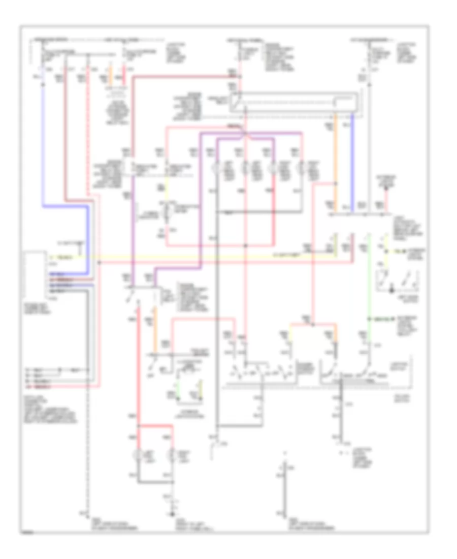
Headlight Wiring Diagram for Mitsubishi 3000GT 1997 3000
List of elements for Headlight Wiring Diagram for Mitsubishi 3000GT 1997 3000:
- A101
- A102
- C10
- C70
- C76
- C77
- C78
- C80
- C82
- C83
- Column switch
- Combination meter
- D04
- Data link connector (partial) (convert: under dash, left of steering column) (ex convert: under dash, right of steering column)
- Dedicated fuse 4 15a
- Dedicated fuse 5 10a
- Dimmer- passing switch
- Engine compartment relay box (on right side of engine compt, near shock tower)
- Etacs unit (under left side of dash)
- Exterior lights system
- Exterior lights system (taillight relay)
- Fog light relay
- Foglight switch
- Front wheelwell)
- Fusible link 3 40a
- G100 (front of left
- G202 (left side of dash,
- Head
- Headlight relay
- Hi beam indicator
- Hot at all times
- Hot in acc or on
- Hot in on or start
- Illumination lamp
- Interior lights system
- Iod or storage connector (in engine compt relay box)
- Junction block (under left side of dash)
- Left door switch
- Left fog- light
- Left high beam head- light
- Left low beam head- light
- Light automatic shut-off unit (behind left rear quarter panel)
- Lighting switch
- Multi- purpose fuse 18 10a
- Multi-purpose fuse 10 15a
- Multi-purpose fuse 19 10a
- Nca
- Off
- On deck crossmember)
- Red
- Right fog- light
- Right high beam head- light
- Right low beam head- light
- Tail
- W/ anti-theft
HORN
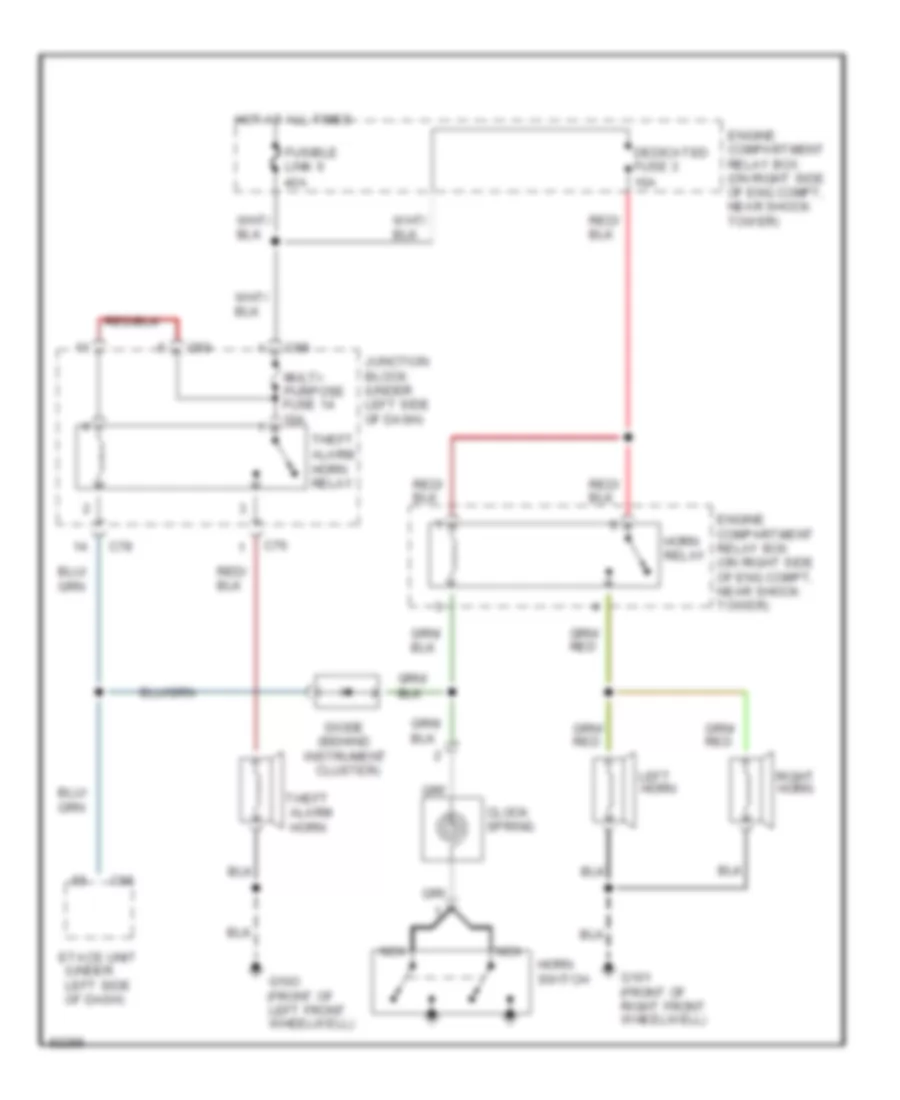
Horn Wiring Diagram, with Anti-theft for Mitsubishi 3000GT 1997 3000
List of elements for Horn Wiring Diagram, with Anti-theft for Mitsubishi 3000GT 1997 3000:
- (behind
- C66
- C68
- C76
- C78
- C80
- Clock spring
- Cluster)
- Dedicated fuse 3 10a
- Diode
- Engine compartment relay box (on right side of eng compt, near shock tower)
- Etacs unit (under left side of dash)
- Fusible link 6 40a
- G101 (front of right front wheelwell)
- G10o (front of left front wheelwell)
- Horn
- Horn relay
- Horn switch
- Hot at all times
- Instrument
- Junction block (under left side of dash)
- Left horn
- Multi- purpose fuse 14 10a
- Nca
- Right horn
- Theft alarm
- Theft alarm horn relay
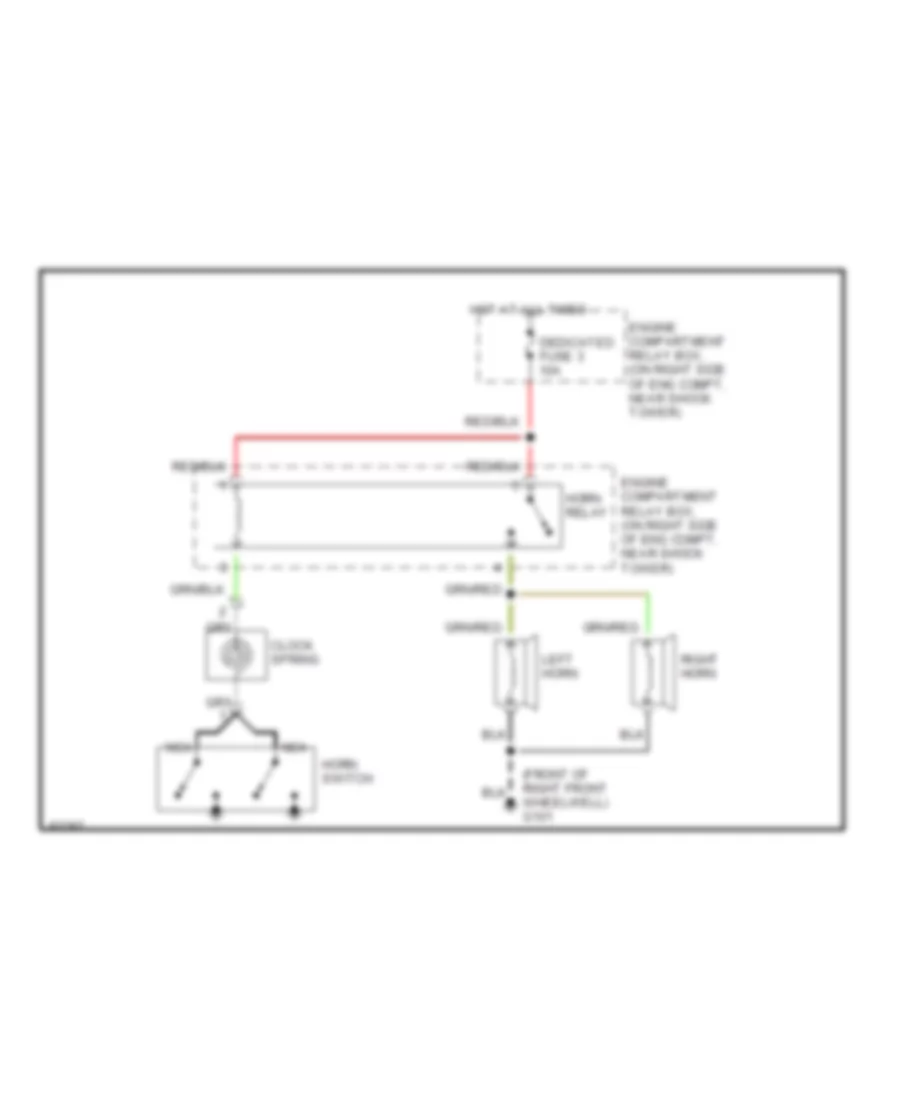
Horn Wiring Diagram, without Anti-theft for Mitsubishi 3000GT 1997 3000
List of elements for Horn Wiring Diagram, without Anti-theft for Mitsubishi 3000GT 1997 3000:
- (front of right front wheelwell) g101
- Clock spring
- Dedicated fuse 3 10a
- Engine compartment relay box, (on right side of eng compt, near shock tower)
- Horn relay
- Horn switch
- Hot at all times
- Left horn
- Nca
- Right horn
INSTRUMENT CLUSTER
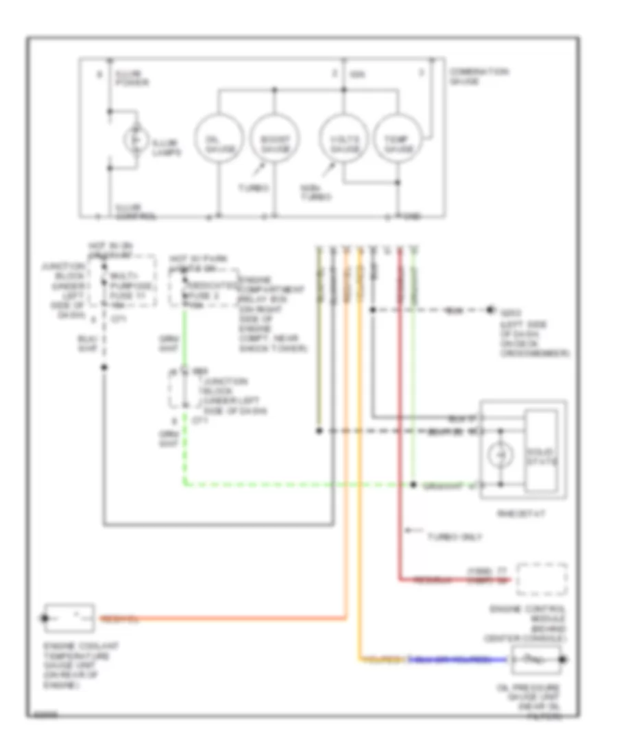
Auxiliary Gauges Wiring Diagram for Mitsubishi 3000GT 1997 3000
List of elements for Auxiliary Gauges Wiring Diagram for Mitsubishi 3000GT 1997 3000:
- (1998) (1997)
- (left side of dash, on deck crossmember)
- Boost gauge
- C69
- C71
- Combination gauge
- Dedicated fuse 2 15a
- Engine compartment relay box (on right side of engine compt, near shock tower)
- Engine control module (behind center console)
- Engine coolant temperature gauge unit (on rear of engine)
- G202
- Gnd
- Hot in on or start
- Hot w/ park lights on
- Ign
- Illum control
- Illum lamps
- Illum power
- Junction block (under left side of dash)
- Junction block (under left side of dash)
- Multi- purpose fuse 11 15a
- Non- turbo
- Oil gauge
- Oil pressure gauge unit (near oil filter)
- Rheostat
- Solid state
- Temp gauge
- Turbo
- Turbo only
- Volts gauge
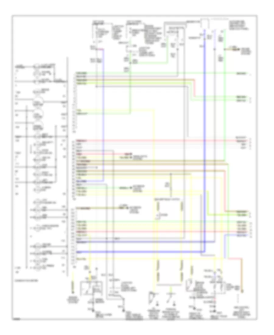
Instrument Cluster Wiring Diagram (1 of 2) for Mitsubishi 3000GT 1997 3000
List of elements for Instrument Cluster Wiring Diagram (1 of 2) for Mitsubishi 3000GT 1997 3000:
- (below trunk latch)
- (front of left front wheelwell)
- (mil)
- 4ws ind
- Abs control unit (behind right rear quarter panel)
- Abs ind
- Asc on ind
- Auto-cruise control unit (behind right
- Bat
- Brake fluid level sensor (in brake fluid reservoir)
- Brake ind
- C69
- C71
- C82
- Charge ind
- Check engine ind
- Combination meter
- Cruise control system
- Cruise ind
- Dedicated fuse 2 15a
- Diode
- Door ajar ind
- Engine compartment relay box (on right side of engine compartment, near shock tower)
- Engine controls system
- Exterior lights system
- Fuel gauge
- Fuel gauge unit
- Fuel ind
- G100
- G123 (below wiper motor)
- G202 (left side of dash, on deck crossmember)
- G407
- Generator
- Gnd
- Hatch convertible
- Headlights system
- Hi beam ind
- Hot in on or start
- Hot w/ park lights on
- Ign
- Illum control
- Illum lamps (5 bulbs)
- Illum power
- Junction block (under left side of dash)
- Left turn ind
- Low washer ind
- Multi- purpose fuse 11 15a
- Nca
- Od off ind
- Oil press ind
- Oil pressure switch (near oil filter)
- Parking brake switch (at base of parking brake lever)
- Power ind
- Red
- Rheostat
- Right turn ind
- Seat belt ind
- Security ind
- Side kick panel)
- Solid state
- Speed sensor
- Speed- ometer
- Srs ind
- Tach- ometer
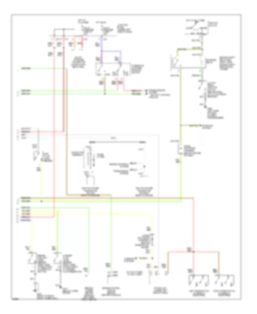
Instrument Cluster Wiring Diagram (2 of 2) for Mitsubishi 3000GT 1997 3000
List of elements for Instrument Cluster Wiring Diagram (2 of 2) for Mitsubishi 3000GT 1997 3000:
- (1997)
- (1998)
- (elc-4a/t control
- (in eng compt relay box)
- 4ws fluid level sender
- Acc
- C70
- C71
- C81
- Capacitor assembly
- Clutch pedal position switch (behind dash, on clutch pedal bracket)
- Connector
- Diode (on wiring harness, behind center of dash)
- Diode (on wiring harness, behind combination meter)
- Dohc
- Eco
- Engine compt relay box (right side engine compt, near shock tower)
- Engine control module (behind center console)
- Engine controls system
- Engine coolant level sensor (right side of eng compt, in overflow bottle)
- Etacs unit (under left side of dash)
- G101 (front of right front wheelwell)
- G123 (below wiper motor)
- G202 (left side of dash, on deck crossmember)
- Hot at all times
- Hot in on
- Ignition power transistor (on right rear of engine)
- Ignition power transistor (on top front of engine)
- Ignition switch
- Iod or storage
- Junction block (under left side of dash)
- Left door switch (closed w/ door open)
- Lock
- Module)
- Multi- purpose fuse 19 10a
- Multi- purpose fuse 7 10a
- Noise filter
- O/d off
- O/d on
- Overdrive & power/ economy switch
- Pwr
- Red
- Right door switch (closed w/ door open)
- Run
- Sohc
- Srs ecu (under center console, between front seats)
- Start
- Starter relay
- Starting system
- System
- Transmission system
- Transmissions
- W/ anti-theft
- W/o anti-theft
- Warning systems
- Washer fluid level sensor (right side of eng compt, in washer fluid reservoir)
INTERIOR LIGHTS
Courtesy Lamps Wiring Diagram, Convertible for Mitsubishi 3000GT 1997 3000
List of elements for Courtesy Lamps Wiring Diagram, Convertible for Mitsubishi 3000GT 1997 3000:
- (no connection)
- C101
- C102
- C70
- C71
- C77
- C80
- C81
- C83
- Combination meter
- D04
- Data link connector (partial) (under dash, left of steering column)
- Door ind
- Door switch
- Etacs control unit (under left side of dash)
- G202 (left side of dash, on deck crossmember)
- Hot at all times
- Hot in on or start
- Ignition key cylinder illumi- nation light
- Iod or storage connector (in eng compt relay box)
- Junction block (under left side of dash)
- Left
- Left door light
- Left foot light
- Left rear courtesy light
- Multi- purpose fuse 11 15a
- Multi- purpose fuse 19 10a
- Red
- Right
- Right door light
- Right foot light
- Right rear courtesy light
Courtesy Lamps Wiring Diagram, Hatchback for Mitsubishi 3000GT 1997 3000
List of elements for Courtesy Lamps Wiring Diagram, Hatchback for Mitsubishi 3000GT 1997 3000:
- C101
- C102
- C65
- C66
- C70
- C71
- C74
- C77
- C80
- C81
- C83
- Combination meter
- D04
- Data link connector (partial) (under dash, right of steering column)
- Dome light
- Door
- Door ind
- Door switch
- Etacs control unit (under left side of dash)
- G202 (left side of dash, on deck crossmember)
- Hot at all times
- Hot in on or start
- Ignition key cylinder illumi- nation light
- Iod or storage connector (in eng compt relay box)
- Junction block (under left side of dash)
- Left
- Left door light
- Left foot light
- Luggage compart- ment light
- Luggage compart- ment light switch
- Map light
- Multi- purpose fuse 11 15a
- Multi- purpose fuse 19 10a
- Off
- Red
- Right
- Right door light
- Right foot light
- W/ anti-theft
- W/o anti-theft
Instrument Illumination Wiring Diagram for Mitsubishi 3000GT 1997 3000
List of elements for Instrument Illumination Wiring Diagram for Mitsubishi 3000GT 1997 3000:
- (1997)
- (1998)
- (2)
- (5 bulbs)
- (left side of dash, on deck crossmember) g202
- Air conditioning control unit (auto a/c)
- Air conditioning switch
- All times
- Ashtray illumination light
- C16
- C17
- C69
- C70
- C71
- C74
- C77
- C78
- C82
- C83
- Cigarette lighter
- Column switch
- Combination gauge
- Combination meter
- D03
- D47
- Defogger switch
- Engine compartment relay box (on right side of engine compt, near right shock tower)
- Fog light switch
- From junction block (diagram 1 of 1)
- Fuse 2 15a
- Fusible link 3 40a
- Glove box illumination light
- Glove box illumination light switch
- Hatchback only
- Hazard switch
- Head
- Heater control panel
- Hot at
- Hot at all times
- Hot in run or start
- Ill
- Illumination
- Inspection light
- Inspection light switch
- Instrument cluster system
- Iod or storage connector (in eng compt relay box)
- Junction block (under left side of dash)
- Left vanity mirror light
- Light automatic shut-off unit (behind left rear quarter panel)
- Lighting switch
- Main switch (cruise control)
- Multi- purpose fuse 18 10a
- Multi- purpose fuse 19 10a
- O/d & power/ economy switch
- Od off ind.
- Off
- Power ind.
- Radio & tape player
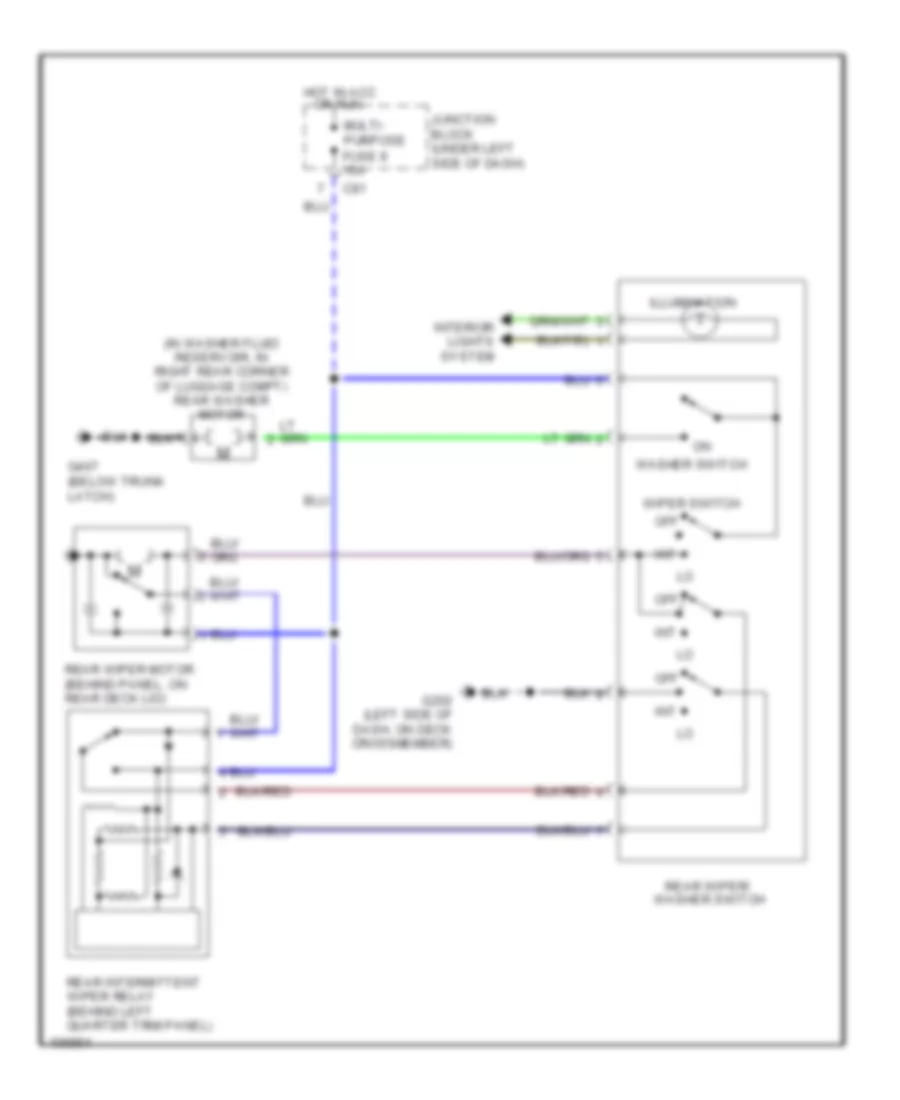
- Rear wiper & washer switch
- Red
- Rheostat
- Right vanity mirror light
- Solid state
- Tail
- Tail- light relay
- To junction block (diagram 1 of 1)
PASSIVE RESTRAINTS
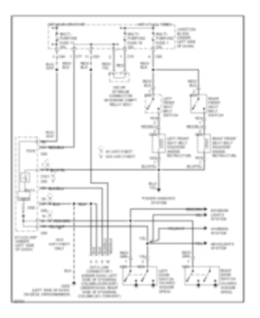
Electric Tension Reducer Wiring Diagram for Mitsubishi 3000GT 1997 3000
List of elements for Electric Tension Reducer Wiring Diagram for Mitsubishi 3000GT 1997 3000:
- (in engine compt relay box)
- C101
- C65
- C66
- C70
- C77
- C80
- C83
- Connector
- Data
- Data link connector 1 (under dash, left side of steering column) (convert) (under dash, right side of steering column) (ex convert)
- Etacs unit (under left side of dash)
- G202 (left side of dash, on deck crossmember)
- Gnd
- Headlights system
- Hot at all times
- Hot in 0n or start
- Interior lights system
- Iod or storage
- Junction block (under left side of dash)
- Left door switch (closed w/door open)
- Left front seat belt solenoid (inside retractor)
- Left front seat belt switch
- Multi- purpose fuse 1 10a
- Multi- purpose fuse 11 15a
- Multi- purpose fuse 19 10a
- Nca
- Power windows system
- Pwr
- Red
- Right door switch (closed w/door open)
- Right front seat belt solenoid (inside retractor)
- Right front seat belt switch
- Timer
- W/ anti-theft
- W/o anti-theft
- W/o anti-theft only
- Warning system
POWER ANTENNA
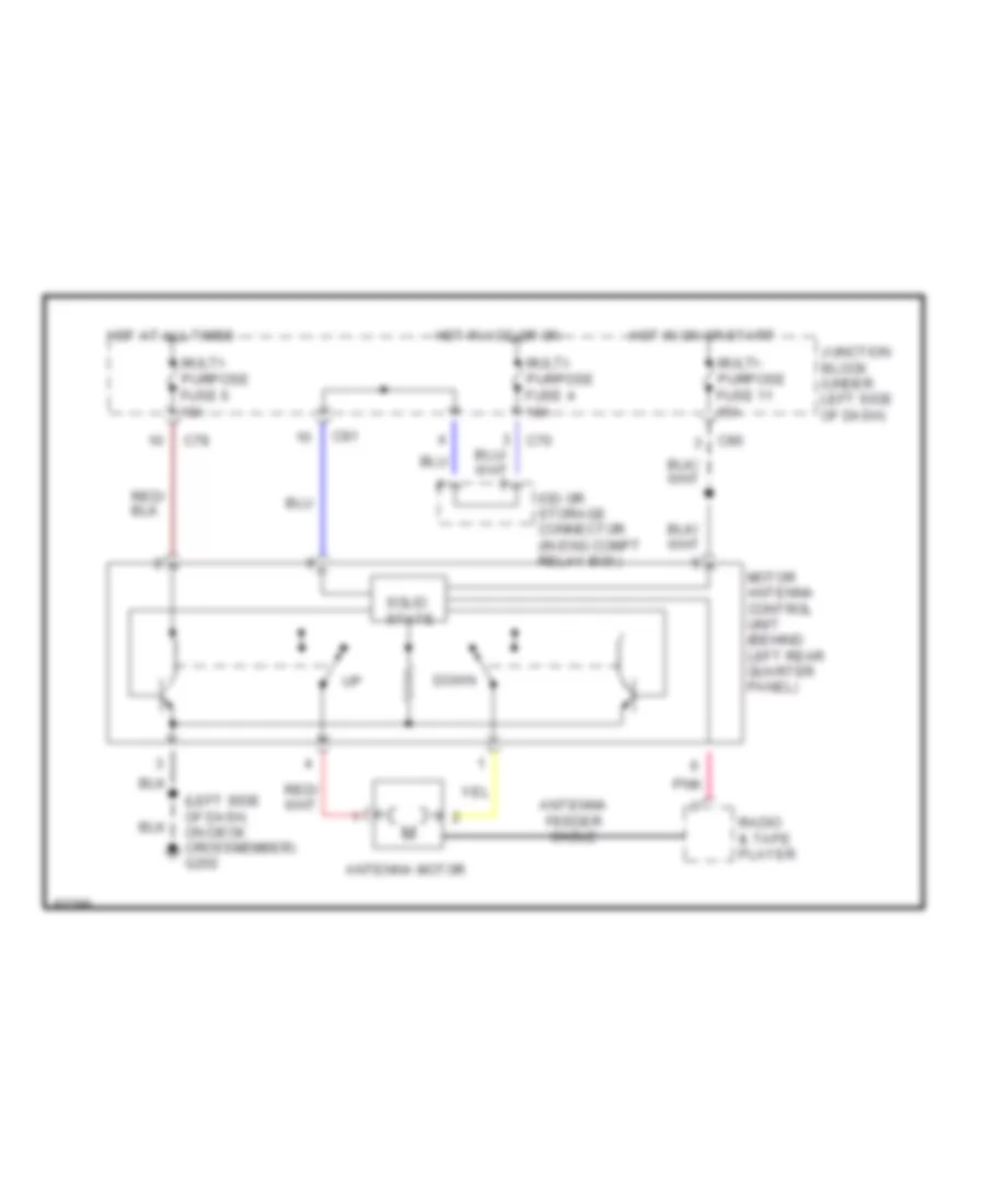
Power Antenna Wiring Diagram, Convertible for Mitsubishi 3000GT 1997 3000
List of elements for Power Antenna Wiring Diagram, Convertible for Mitsubishi 3000GT 1997 3000:
- (left side of dash, on deck crossmember) g202
- Antenna feeder cable
- Antenna motor
- C70
- C78
- C80
- C81
- Down
- Hot at all times
- Hot in acc or on
- Hot in on or start
- Iod or storage connector (in eng compt relay box)
- Junction block (under left side of dash)
- Motor antenna control unit (behind left rear quarter panel)
- Multi- purpose fuse 11 15a
- Multi- purpose fuse 4 10a
- Multi- purpose fuse 6 10a
- Pnk
- Radio & tape player
- Solid state
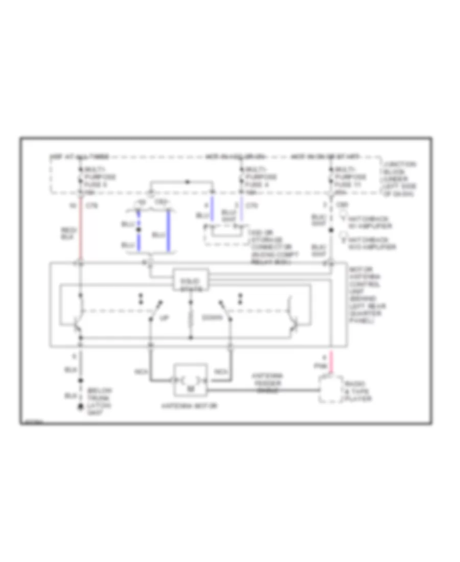
Power Antenna Wiring Diagram, Hatchback for Mitsubishi 3000GT 1997 3000
List of elements for Power Antenna Wiring Diagram, Hatchback for Mitsubishi 3000GT 1997 3000:
- (below trunk latch) g407
- Antenna feeder cable
- Antenna motor
- C70
- C78
- C80
- C81
- Down
- Hatchback
- Hot at all times
- Hot in acc or on
- Hot in on or start
- Iod or storage connector (in eng compt relay box)
- Junction block (under left side of dash)
- Motor antenna control unit (behind left rear quarter panel)
- Multi- purpose fuse 11 15a
- Multi- purpose fuse 4 10a
- Multi- purpose fuse 6 10a
- Nca
- Pnk
- Radio & tape player
- Solid state
- W/ amplifier
- W/o amplifier
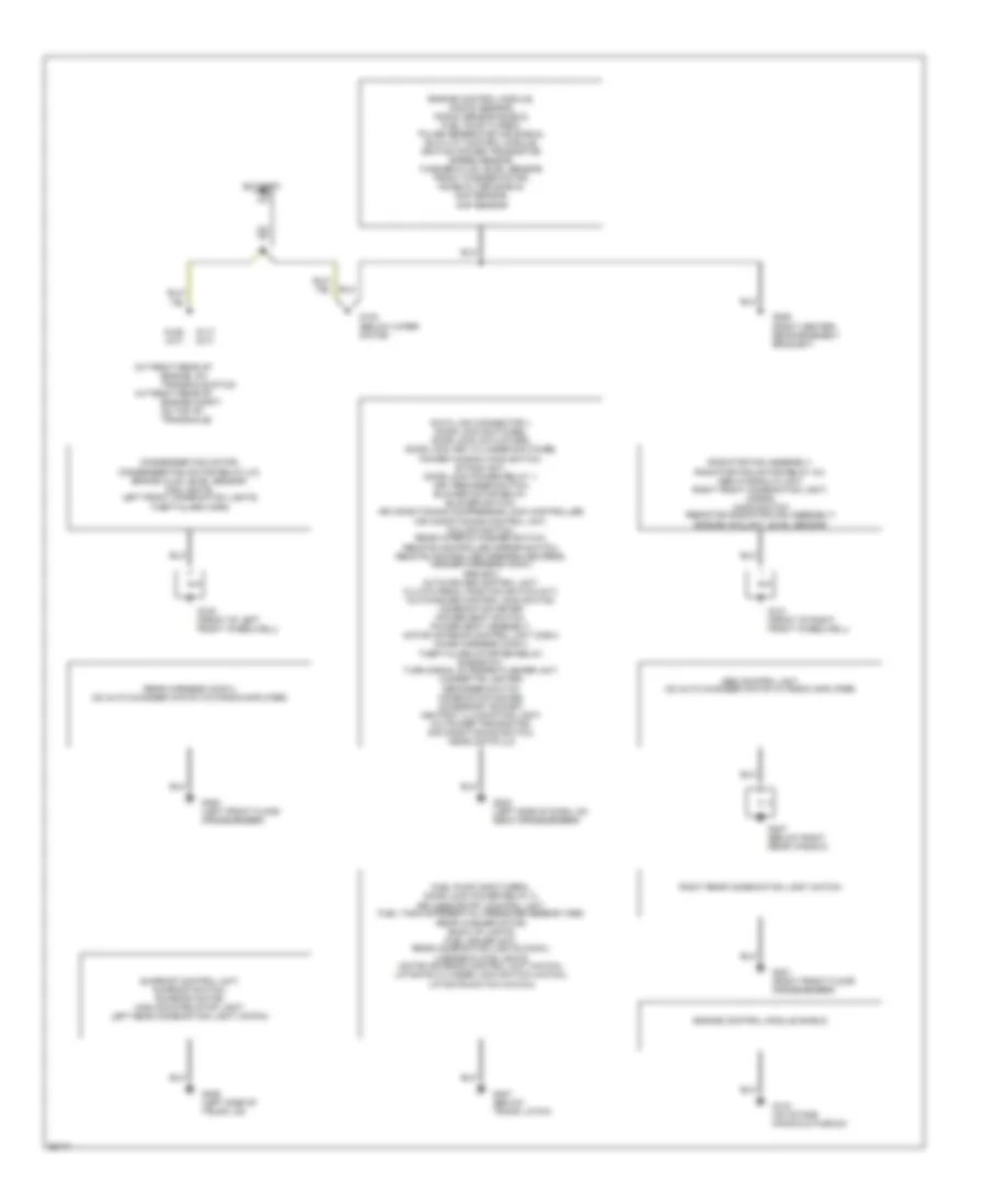
POWER DISTRIBUTION
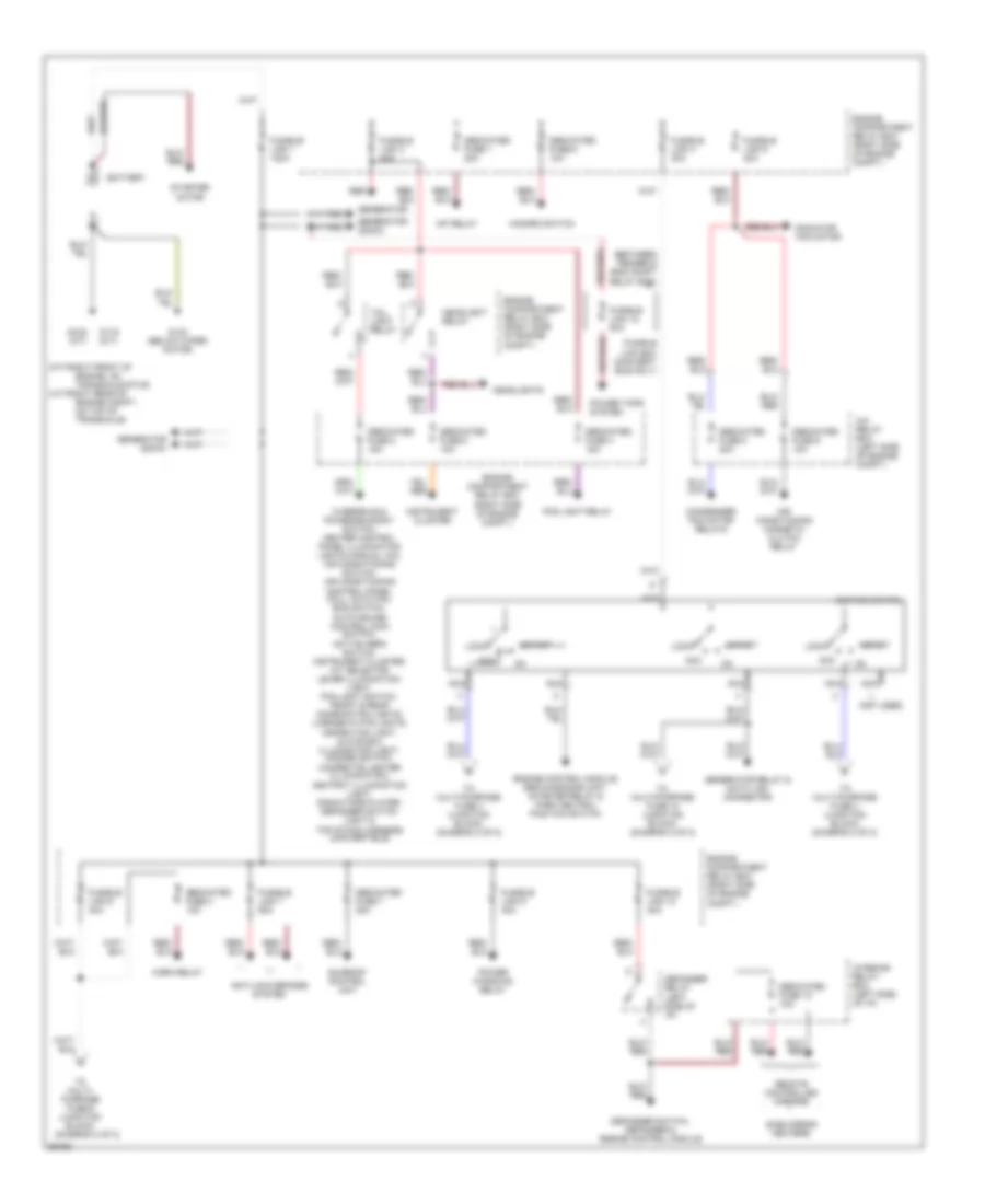
Power Distribution Wiring Diagram (1 of 2) for Mitsubishi 3000GT 1997 3000
List of elements for Power Distribution Wiring Diagram (1 of 2) for Mitsubishi 3000GT 1997 3000:
- (a/t-right rear of
- (between fender & eng compt relay box)
- (diagram 2 of 2)
- (m/t-right front of
- (not used)
- A/c relay box (left side of engine compt.)
- Acc
- Air conditioning magnetic clutch relay
- Anti-lock brakes system
- Battery
- Condenser fan motor relays
- Dedicated fuse 1 20a
- Dedicated fuse 1o 10a
- Dedicated fuse 2 15a
- Dedicated fuse 3 10a
- Dedicated fuse 4 15a
- Dedicated fuse 5 10a
- Dedicated fuse 6 10a
- Dedicated fuse 7 20a
- Dedicated fuse 8 20a
- Dedicated fuse 9 10a
- Defogger relay (left side of i/p)
- Defogger switch, defogger & engine control module
- Engine compartment relay box (right side of engine compt.)
- Engine compt., on top of transaxle)
- Engine control module, srs diagnosis unit, starter relay & park neutral position switch
- Engine, on transaxle stud)
- Fog light relay
- Fusible link 1 120a
- Fusible link 10 40a
- Fusible link 12 80a
- Fusible link 3 40a
- Fusible link 4 30a
- Fusible link 5 40a
- Fusible link 6 40a
- Fusible link 7 60a
- Fusible link 9 30a
- Fusible link box (convert- ible only)
- G119 (m/t)
- G123 (below wiper motor)
- G129 (a/t)
- Generator
- Generator (dohc)
- Generator (sohc)
- Generator relay & data link connector
- Hazard switch
- Headlight relay
- Headlights
- Horn relay
- Ignition switch
- Instrument cluster
- Interior relay box (left side of i/p)
- Lock
- Mfi relay
- Nca
- Overdrive & power/economy switch, heater control panel illumination lights (manual a/c), air conditioning switch, air conditioning control panel (full auto a/c), ecs switch, auto-cruise control main switch, active aero switch, instrument cluster, a/t selector lever illumination, light, fog light switch, front & rear combination lights, license plate lights, inspection light, glove box illumination light, hazard switch, cigarette lighter (illumination), ashtray illumination light, radio/tape player, defogger switch light & top stack harness (convertible)
- Power tops system
- Power windows relay
- Radiator fan motor
- Red
- Remote controlled mirrors
- Side mirror heaters
- Start
- Starter motor
- Sunroof control unit
- Tail light relay
- To multi- purpose fuse 6 (junction block)
- To multi-purpose fuse 18 (junction block) (diagram 2 of 2)
- To multi-purpose fuse 3 (junction block) (diagram 2 of 2)
- To multi-purpose fuse 4 (junction block) (diagram 2 of 2)
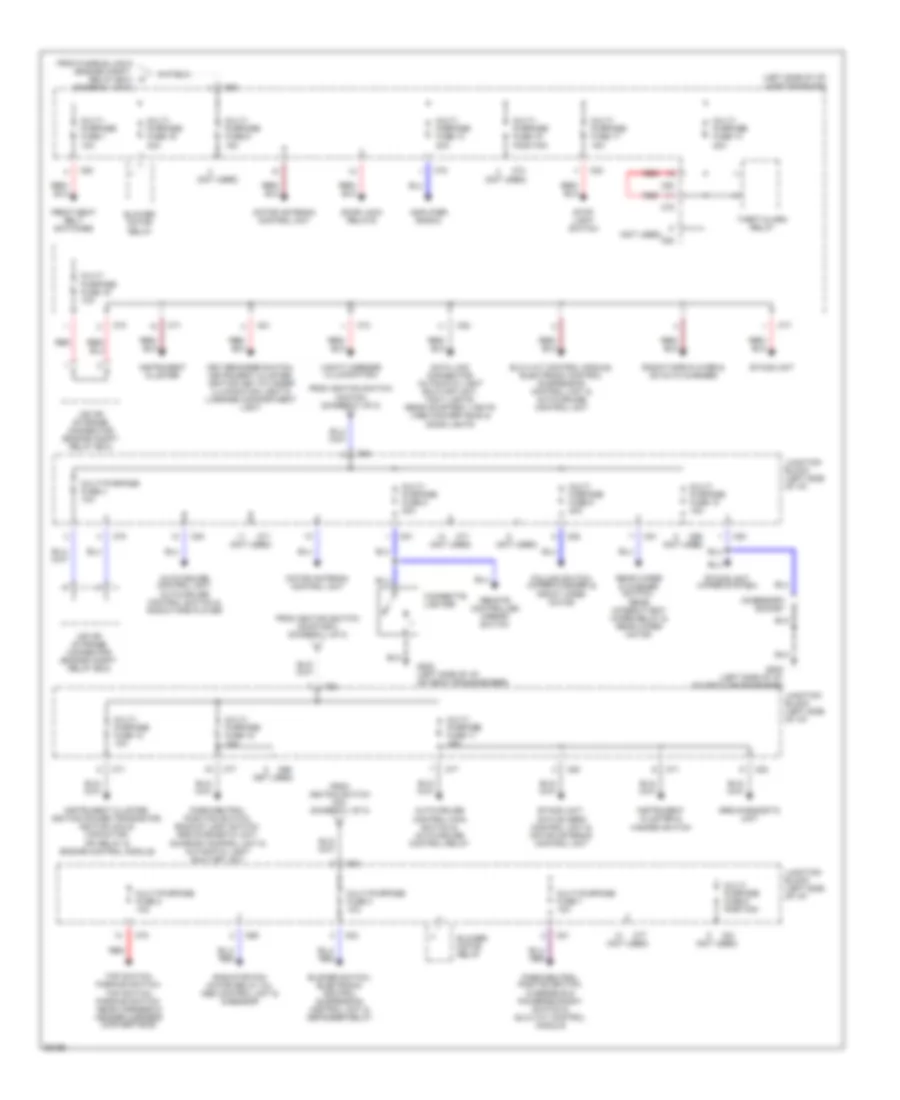
Power Distribution Wiring Diagram (2 of 2) for Mitsubishi 3000GT 1997 3000
List of elements for Power Distribution Wiring Diagram (2 of 2) for Mitsubishi 3000GT 1997 3000:
- (left side of i/p) junction block
- (not used)
- Accessory socket
- Amplifier (radio)
- Auto-cruise control main switch & auto-cruise control relay
- Auto-cruise control unit, auto-cruise control switch & radio/tape player
- Blower motor relay
- Blower switch, electronic control suspension control unit & defogger relay
- C68
- C69
- C70
- C71
- C74
- C77
- C78
- C80
- C81
- C82
- C83
- Cigarette lighter
- Column switch (wiper/washer) & front wper motor
- Data link connector, automatic light shut-off unit, foot lights, rear courtesy lights (1996 convertible) & door lights
- Door lock relays
- Elc-4 a/t control module, electronic control suspension control unit & auto-cruise control unit
- Etacs unit
- Etacs unit (wiper system)
- Etacs unit, active aero control unit & motor antenna control unit
- From fusible link 6 (engine compt. relay box) (diagram 1 of 2)
- From ignition switch (acc/on) (diagram 1 of 2)
- From ignition switch (on) (diagram 1 of 2)
- From ignition switch (on/start) (diagram 1 of 2)
- Front seat belt switches
- G202 (left side of i/p, on deck crossmember)
- Instrument cluster
- Instrument cluster & hazard switch
- Instrument cluster, ignition power transistor, ignition coils, capacitor, mfi relay & engine control module
- Iod or storage connector (engine compt. relay box)
- Junction block (left side of i/p)
- Key reminder switch, instrument cluster, ignition key cylinder illumination light & luggage compartment light
- Motor antenna control unit
- Multi- purpose fuse 1 10a
- Multi- purpose fuse 10 15a
- Multi- purpose fuse 11 15a
- Multi- purpose fuse 12 10a
- Multi- purpose fuse 13 20a
- Multi- purpose fuse 14 20a
- Multi- purpose fuse 15 position
- Multi- purpose fuse 16 30a
- Multi- purpose fuse 17 15a
- Multi- purpose fuse 18 10a
- Multi- purpose fuse 19 10a
- Multi- purpose fuse 5 20a
- Multi- purpose fuse 6 15a
- Multi- purpose fuse 8 position
- Multi- purpose fuse 9 20a
- Multi-purpose fuse 2 10a
- Multi-purpose fuse 3 10a
- Multi-purpose fuse 4 10a
- Multi-purpose fuse 7 10a
- Park/neutral position switch, backup light switch, srs diagnostic unit, sunroof control unit & automatic light shut-off unit
- Park/neutral postion switch, overdrive & power/economy switch & elc-4 a/t control module
- Radiator fan motor relay (hi), abs control unit & g-sensor
- Radio/tape player & cd auto changer
- Rear wiper & washer switch, rear intermittent wiper relay & rear wiper motor
- Red
- Remote controlled mirror switch
- Srs diagnostic unit
- Stop light switch
- Theft-alarm relay
- Top switch, parking switch, top switch, parking switch, rear harness & header harness (convertible)
- Vanity mirrors (illumination)
POWER DOOR LOCKS
Power Door Lock Wiring Diagram (1 of 2) for Mitsubishi 3000GT 1997 3000
List of elements for Power Door Lock Wiring Diagram (1 of 2) for Mitsubishi 3000GT 1997 3000:
- (behind left rear quarter panel)
- C70
- C77
- C78
- C81
- C82
- C83
- Data link connector (right of steering column)
- Etacs unit (under left side of dash)
- Feeder antenna
- Fuse 10a
- Fuse 15a
- G202 (left side of dash, on deck crossmember)
- G407 (below trunk latch)
- Hot at all times
- Hot in acc or run
- Interior lights system (dome & foot lamps)
- Iod or storage connector
- Junction block (left side of dash)
- Key reminder switch (w/ anti- theft system)
- Key reminder switch (w/o anti- theft system)
- Keyless entry control unit
- Left door switch (closed w/door open)
- N/a
- Red
- Right door switch (closed w/door open)
- W/ theft alarm
- W/o theft alarm
Power Door Lock Wiring Diagram (2 of 2) for Mitsubishi 3000GT 1997 3000
List of elements for Power Door Lock Wiring Diagram (2 of 2) for Mitsubishi 3000GT 1997 3000:
- Door lock power relay 1 (under left side of dash)
- Door lock power relay 2 (behind left quarter trim panel)
- G202 (left side of dash, on deck crossmember)
- G407 (below trunk latch)
- Left door lock actuator
- Left door lock key cylinder switch
- Left door lock switch
- Lock
- Right door lock actuator
- Right door lock key cylinder switch
- Right door lock switch
- Unlock
- W/ power windows
- W/o power windows
POWER MIRRORS
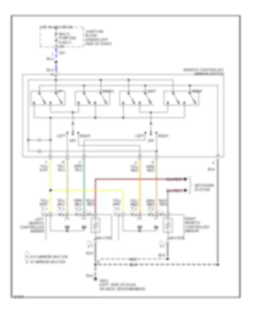
Power Mirror Wiring Diagram for Mitsubishi 3000GT 1997 3000
List of elements for Power Mirror Wiring Diagram for Mitsubishi 3000GT 1997 3000:
- C81
- Defogger system
- Down
- G202 (left side of dash, on deck crossmember)
- Heater
- Hot in acc or on
- Junction block (under left side of dash)
- Left
- Left remote controlled mirror
- Multi- purpose fuse 5 15a
- Off
- Remote controlled mirror switch
- Right
- Right remote controlled mirror
- W/ mirror heater
- W/o mirror heater
POWER SEATS
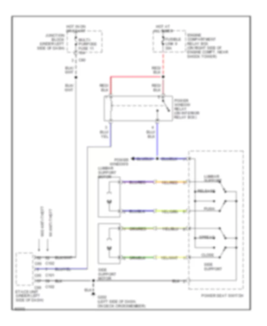
Power Lumbar Seat Wiring Diagram for Mitsubishi 3000GT 1997 3000
List of elements for Power Lumbar Seat Wiring Diagram for Mitsubishi 3000GT 1997 3000:
- C101
- C102
- C65
- C66
- C80
- Close
- Engine compartment relay box (on right side of engine compt, near shock tower)
- Etacs unit (under left side of dash)
- Fusible link 9 30a
- G202 (left side of dash, on deck crossmember)
- Hot at all times
- Hot in on or start
- Junction block (under left side of dash)
- Lumbar support
- Lumbar support motor
- Multi- purpose fuse 11 15a
- Power seat switch
- Power window relay (on interior relay box)
- Power windows
- Push
- Release
- Side support
- Side support motor
- Spread
- W/ anti-theft
- W/o anti-theft
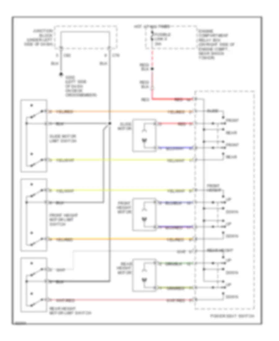
Power Seat Wiring Diagram for Mitsubishi 3000GT 1997 3000
List of elements for Power Seat Wiring Diagram for Mitsubishi 3000GT 1997 3000:
- C78
- C82
- Down
- Engine compartment relay box (on right side of engine compt, near shock tower)
- Front
- Front height
- Front height motor
- Front height motor limit switch
- Fusible link 9 30a
- G202 (left side of dash, on deck crossmember)
- Height motor
- Hot at all times
- Junction block (under left side of dash)
- Motor
- Power seat switch
- Rear
- Rear height
- Rear height motor limit switch
- Red
- Slide
- Slide motor limit switch
POWER TOP/SUNROOF
Retractable Hardtop Provision for Mitsubishi 3000GT 1997 3000
List of elements for Retractable Hardtop Provision for Mitsubishi 3000GT 1997 3000:
- C69
- C70
- C74
- C77
- C78
- C83
- Chime
- Cruise control system
- D48
- D52
- D53
- Data link connector (under dash, left of steering column)
- Dedicated fuse 2 15a
- Defogger system (defogger relay)
- Engine compartment relay box (on right side of engine compt, near shock tower)
- Exterior lights system
- Exterior lights system (back-up light switch or park/ neutral position switch)
- F46
- F47
- F48
- F51
- Fusible link 12 80a
- Fusible link box (on right side of engine compartment near shock tower)
- G202 (left side of dash, on deck crossmember)
- G300 (left front floor crossmember)
- Header harness
- Hot at all times
- Hot in run
- Hot in run or start
- Hot with taillight relay energized
- Instrument cluster system (vehicle speed sensor)
- Instrument cluster, warning systems
- Interior lights system (foot lights, etacs ecu)
- Iod or storage connector (in eng compt relay box)
- Junction block (under left side of dash)
- Multi- purpose fuse 18 10a
- Multi- purpose fuse 2 10a
- Multi- purpose fuse 219 10a
- Nca
- Parking brake switch (at base of parking brake lever)
- Pnk
- Rear harness
- Red
- Top switch
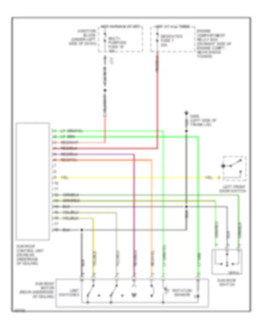
Sunroof Wiring Diagram for Mitsubishi 3000GT 1997 3000
List of elements for Sunroof Wiring Diagram for Mitsubishi 3000GT 1997 3000:
- C77
- Dedicated fuse 7 20a
- Engine compartment relay box (on right side of engine compt, near shock tower)
- G406 (left side of trunk lid)
- Hot at all times
- Hot in run & start
- Junction block (under left side of dash)
- Left front door switch
- Limit switches
- Multi- purpose fuse 18 10a
- Open
- Rotation sensor
- Sun roof control unit (on rear underside of ceiling)
- Sun roof motor (rear underside of ceiling)
- Sun roof switch
POWER WINDOWS
Power Window Wiring Diagram for Mitsubishi 3000GT 1997 3000
List of elements for Power Window Wiring Diagram for Mitsubishi 3000GT 1997 3000:
- (3 leds)
- C70
- C77
- C80
- C83
- Data link connector (convertible: under dash, left of steering column) (ex convertible: under dash, right of steering column)
- Down
- Down circuit
- Engine compartment relay box (on right side of engine compt, near shock tower)
- Etacs unit (under left side of dash)
- Fusible link 9 30a
- G202 (left side of of dash, on deck crossmember)
- Hot at all times
- Hot in run or start
- Iod or storage connector (in eng compt relay box)
- Junction block (under left side of dash)
- Left door switch (closed w/ door open)
- Left window motor
- Lock switch
- Multi- purpose fuse 11 15a
- Multi- purpose fuse 19 10a
- Nca
- One touch
- Power window main switch
- Power window sub switch
- Power windows relay (on interior relay box)
- Red
- Right door switch (closed w/ door open)
- Right window motor
- W/ anti-theft
- W/o anti-theft
RADIO
Radio Wiring Diagrams, Convertible for Mitsubishi 3000GT 1997 3000
List of elements for Radio Wiring Diagrams, Convertible for Mitsubishi 3000GT 1997 3000:
- (1996)
- (1997-1998)
- (below trunk latch) g407
- 1996 vftc c
- Amplifier
- Antenna feeder cable
- C70
- C77
- C78
- C80
- C81
- C83
- Clock spring (in steering wheel)
- Criuise control system
- D36
- D47
- Din cable
- G202 (left side of dash, on deck crossmember)
- Glass antenna
- Ground
- Hot at all times
- Hot in acc & run
- Hot in run & start
- Interior lights system
- Iod or storage connector (in engine compt) relay box)
- Junction block (under left side of dash)
- Left door speaker
- Left front speaker
- Motor antenna
- Motor antenna control unit (behind left rear quarter panel)
- Multi- purpose fuse 11 15a
- Multi- purpose fuse 13 15a
- Multi- purpose fuse 19 10a
- Multi- purpose fuse 4 10a
- Multi- purpose fuse 6 10a
- Pnk
- Radio & tape player
- Radio remote control switch
- Red
- Right door speaker
- Right front speaker
Radio Wiring Diagrams, Hatchback with Amplifier for Mitsubishi 3000GT 1997 3000
List of elements for Radio Wiring Diagrams, Hatchback with Amplifier for Mitsubishi 3000GT 1997 3000:
- 1996 vftc c
- Amplifier
- Antenna feeder cable
- C70
- C77
- C78
- C80
- C81
- C83
- Cd auto changer
- Clock spring (in steering wheel)
- Criuise control system
- D36
- D47
- Din cable
- G307 (below right rear window)
- G407 (below trunk latch)
- Glass antenna
- Ground
- Hot at all times
- Hot in acc & run
- Hot in run & start
- Interior lights system
- Iod or storage connector (in engine compt) relay box)
- Junction block (under left side of dash)
- Left door speaker
- Left front speaker
- Left rear speaker
- Motor antenna
- Motor antenna control unit (behind left rear quarter panel)
- Multi- purpose fuse 11 15a
- Multi- purpose fuse 13 15a
- Multi- purpose fuse 19 10a
- Multi- purpose fuse 4 10a
- Multi- purpose fuse 6 10a
- Nca
- Pnk
- Radio & tape player
- Radio remote control switch
- Red
- Right door speaker
- Right front speaker
- Right rear speaker
Radio Wiring Diagrams, Hatchback without Amplifier for Mitsubishi 3000GT 1997 3000
List of elements for Radio Wiring Diagrams, Hatchback without Amplifier for Mitsubishi 3000GT 1997 3000:
- 1994-1996
- 1996 vftc c
- 1997-1999
- Antenna feeder cable
- C70
- C77
- C78
- C80
- C81
- C83
- Cd auto changer
- Clock spring (in steering wheel)
- Criuise control system
- D36
- D47
- Din cable
- G307 (below right rear window)
- G407 (below trunk latch)
- Glass antenna
- Hot at all times
- Hot in acc & run
- Hot in run & start
- Interior lights system
- Iod or storage connector (in engine compt) relay box)
- Junction block (under left side of dash)
- Left door speaker
- Left front speaker
- Left rear speaker
- Motor antenna
- Motor antenna control unit (behind left rear quarter panel)
- Multi- purpose fuse 11 15a
- Multi- purpose fuse 19 10a
- Multi- purpose fuse 4 10a
- Multi- purpose fuse 6 10a
- Nca
- Pnk
- Radio & tape player
- Radio remote control switch
- Red
- Right door speaker
- Right front speaker
- Right rear speaker
STARTING/CHARGING
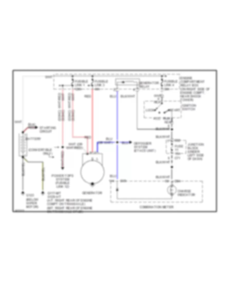
Charging Wiring Diagram for Mitsubishi 3000GT 1997 3000
List of elements for Charging Wiring Diagram for Mitsubishi 3000GT 1997 3000:
- (below wiper motor)
- (convertible only)
- (dohc) (sohc)
- (m/t: right rear of engine on transaxle stud)
- (sohc) (dohc)
- 120a
- 40a
- Acc
- Battery
- C71
- C82
- Charge indicator
- Combination meter
- D04
- D05
- Defogger system (etacs unit)
- Engine compartment relay box (on right side of engine compt, near shock tower)
- Fuse 15a
- Fusible link 1
- Fusible link 3
- Fusible link 4 30a
- G117-m/t g129-a/t (a/t: right rear of engine compt on transaxle)
- G123
- Generator
- Ignition switch
- Junction block (under left side of dash)
- Lock
- Nca
- Power tops system (fusible link 12)
- Red
- Relay
- Run nca
- Start
- Starting circuit
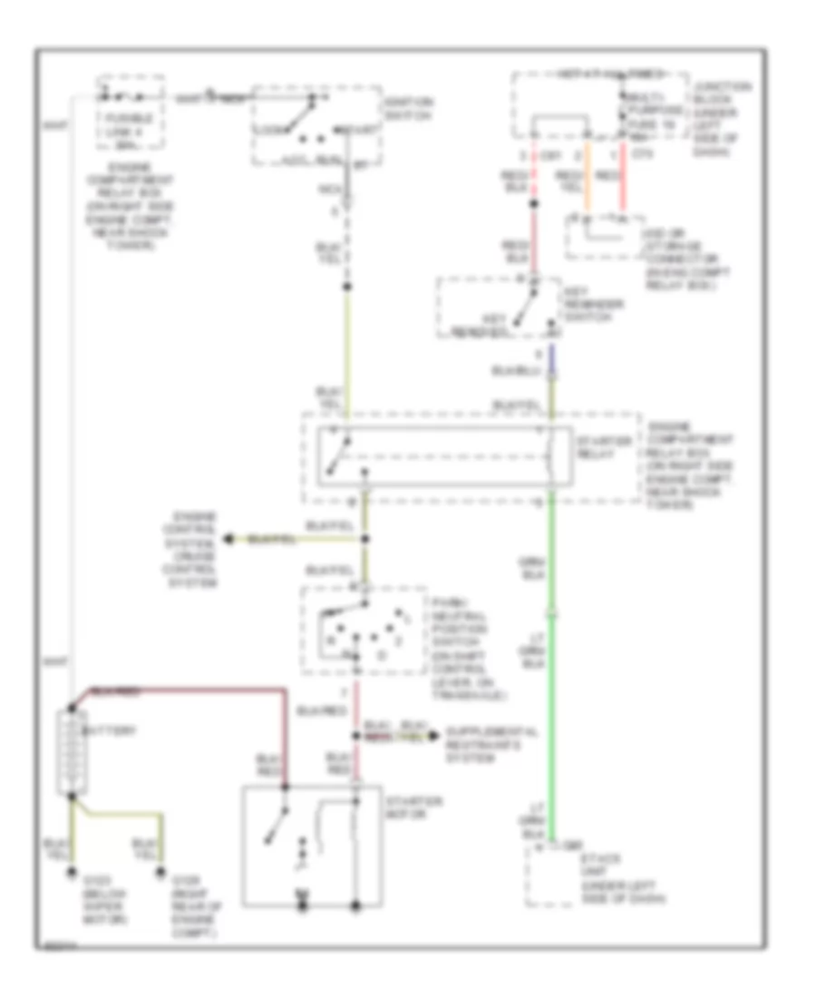
Starting Wiring Diagram, A/T with Anti-Theft for Mitsubishi 3000GT 1997 3000
List of elements for Starting Wiring Diagram, A/T with Anti-Theft for Mitsubishi 3000GT 1997 3000:
- (on shift control lever, on transaxle)
- (under left side of dash)
- 30a
- Acc
- Battery
- C65
- C70
- C81
- Engine compartment relay box (on right side engine compt, near shock tower)
- Engine control
- Etacs unit
- Fusible link 4
- G123 (below wiper motor)
- G129 (right rear of engine compt)
- Hot at all times
- Ignition switch
- Iod or storage connector (in eng compt relay box)
- Junction block (under left side of dash)
- Key reminder switch
- Key removed
- Lock
- Multi- purpose fuse 19 10a
- Nca
- Park/ neutral position switch
- Red/ red
- Run
- Start
- Starter motor
- Starter relay
- System, cruise control system
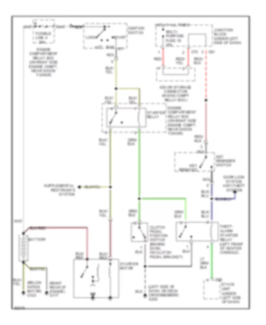
Starting Wiring Diagram, M/T with Anti-Theft for Mitsubishi 3000GT 1997 3000
List of elements for Starting Wiring Diagram, M/T with Anti-Theft for Mitsubishi 3000GT 1997 3000:
- (below wiper motor) g123
- (left side of dash, on deck crossmember) g202
- (right rear of engine) g117
- (under left side of dash)
- 30a
- Acc
- Battery
- C65
- C70
- C81
- Clutch pedal position switch (behind dash, on clutch pedal bracket)
- Door lock system, anti-theft system
- Engine compartment relay box (on right side engine compt, near shock tower)
- Etacs unit
- Fusible link 4
- Hot at all times
- Ignition switch
- Iod or storage connector (in eng compt relay box)
- Junction block (under left side of dash)
- Key reminder switch
- Key removed
- Lock
- Multi- purpose fuse 19 10a
- Nca
- Red
- Restraints
- Run
- Start
- Starter motor
- Starter relay
- Starter relay (left front of center console)
- System
- Theft- alarm
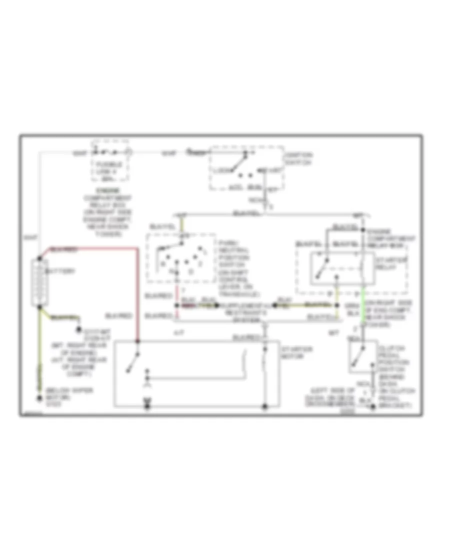
Starting Wiring Diagram, without Anti-theft for Mitsubishi 3000GT 1997 3000
List of elements for Starting Wiring Diagram, without Anti-theft for Mitsubishi 3000GT 1997 3000:
- (below wiper motor) g123
- (m/t: right rear of engine) (a/t: right rear of engine compt)
- (on shift control lever, on transaxle)
- 30a
- A/t
- Acc
- Battery
- Clutch pedal position switch (behind dash, on clutch pedal bracket)
- Engine compartment relay box
- Engine engine compartment relay box (on right side engine compt, near shock tower)
- Fusible link 4
- G117-m/t g129-a/t
- Ignition switch
- Lock
- M/t
- Nca
- Park/ neutral position switch
- Run
- Start
- Starter motor
- Starter relay
SUPPLEMENTAL RESTRAINTS
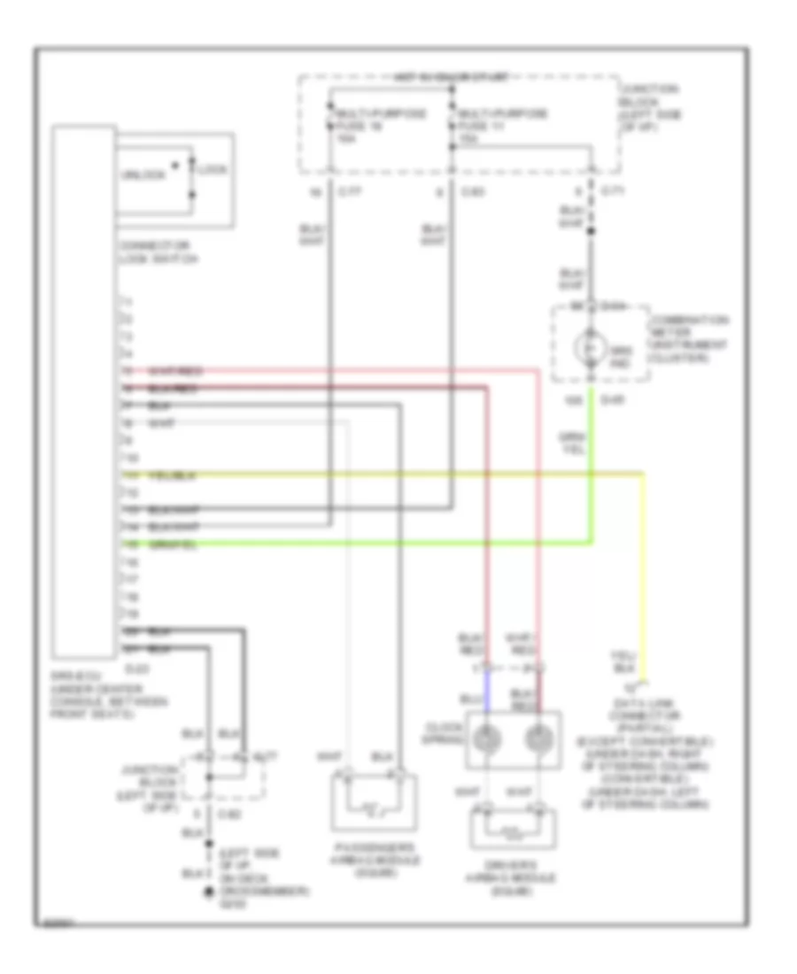
Supplemental Restraint Wiring Diagram for Mitsubishi 3000GT 1997 3000
List of elements for Supplemental Restraint Wiring Diagram for Mitsubishi 3000GT 1997 3000:
- (left side of i/p, on deck crossmember) g202
- C-71
- C-77
- C-82
- C-83
- Clock spring
- Combination meter (instrument cluster)
- Connector lock switch
- D-04
- D-05
- D-23
- Data link connector (partial) (except convertible) (under dash, right of steering column) (convertible) (under dash, left of steering column)
- Driver's airbag module (squib)
- Hot in on or start
- Junction block (left side of i/p)
- Lock
- Multi-purpose fuse 11 15a
- Multi-purpose fuse 18 10a
- Passenger's airbag module (squib)
- Srs ind.
- Srs-ecu (under center console, between front seats)
- Unlock
TRANSMISSION
A/T Wiring Diagram for Mitsubishi 3000GT 1997 3000
List of elements for A/T Wiring Diagram for Mitsubishi 3000GT 1997 3000:
- (left side of dash)
- (on left of transaxle) pulse generators (on top rear of transaxle)
- 4-speed a/t solenoid valve
- A/c relay sig
- A/t oil temperature sensor (right side of transaxle)
- Air conditioning system (thermostat switch)
- Auto-cruise control unit (right kick panel)
- C46
- C47
- C70
- C77
- C81
- Data link connector (below left side of dash)
- Dlc mode ctrl
- Dlc output
- Economy
- Elc-4 a/t control module (behind center console)
- Eng comm sig
- Engine controls system (ecm)
- Engine controls system (power transistor)
- Engine controls system (speed sensor)
- Engine controls sytem (ecm)
- Exterior lights system (back-up)
- Fuse 10a
- G123 (below wiper motor)
- G123 (on firewall behind battery)
- G206 (right center reinforcement bracket)
- Gnd
- Hot at all times
- Hot in run
- Hot in run or start
- Ign pulse
- Ignition switch
- Illum
- Instrument cluster system (ect power)
- Instrument cluster system (od off)
- Interior lights system
- Junction block
- Kickdown servo sw
- Kickdown servo switch (on transaxle)
- Nca
- Nca nca
- O/d sw
- Off
- Oil pressure control solenoid
- Oil temp sen
- Overdrive & power/economy switch
- Park/neutral position switch (on transaxle, at shift control lever)
- Pnk
- Power nca
- Press ctrl sol vlv
- Pulse gen a
- Pulse gen b
- Pwr mode sig
- Pwr source
- Pwr source backup
- R n
- Red
- Sensor gnd
- Shift control solenoid a
- Shift control solenoid b
- Shift ctrl sol
- Shift ctrl sol vlv
- Starter relay
- Starting/ charging system (starter motor)
- Storage connector (in engine center relay box)
- Tcc sol
- Throt pos sen
- Throttle position sensor (throttle body)
- Torque converter clutch sol valve
- Veh spd reed sw
- W/ auto- cruise
- W/ theft- alarm
- W/o auto- cruise
- W/o theft- alarm
WARNING SYSTEMS
Warning System Wiring Diagrams for Mitsubishi 3000GT 1997 3000
List of elements for Warning System Wiring Diagrams for Mitsubishi 3000GT 1997 3000:
- (convertible: under dash, left of steering column) (coupe: under dash, right side of steering column)
- (left side of dash, on deck crossmember) g202
- Buzzer (on right center dash support)
- C101
- C102
- C65
- C66
- C70
- C80
- C81
- C83
- Combination meter
- D05
- Data link connector
- Diode (behind combi- nation meter)
- Diode (behind combination meter)
- Etacs unit (under left side of dash)
- Hot at all times
- Hot in on or start
- Interior lights system
- Iod or storage connector (in eng compt relay box)
- Junction block (under left side of dash)
- Key reminder switch (closed w/ key removed)
- Left door switch (closed w/ door open)
- Multi-purpose fuse 11 15a
- Multi-purpose fuse 19 10a
- Nca
- Red
- Seat belt indicator
- Seat belt switch (open w/ belt buckled)
- Timer circuit
- W/ anti- theft
- W/o anti- theft
WIPER/WASHER
Front Wiper/Washer Wiring Diagram for Mitsubishi 3000GT 1997 3000
List of elements for Front Wiper/Washer Wiring Diagram for Mitsubishi 3000GT 1997 3000:
- (below wiper motor) g123
- (ex convertible: under dash, right of steering column) (convertible: under dash, left of steering column) data link connector 1
- (left side of dash, on deck crossmember) g202
- C101
- C102
- C65
- C66
- C82
- C83
- Column switch
- Etacs unit (under left side of dash)
- Fast
- Front washer motor (in washer fluid reservoir, near battery)
- Front wiper motor (on right rear of eng compt)
- Hot in acc or on
- Int
- Intermit- tent time detection circuit
- Intermittent
- Junction block (under left side of dash)
- Multi- purpose fuse 9 15a
- Off
- Slow
- Timer circuit
- W/ anti-theft
- W/o anti-theft
- Washer switch
- Washer switch on interval detector circuit
- Wiper relay
- Wiper switch
Rear Wiper/Washer Wiring Diagram for Mitsubishi 3000GT 1997 3000
List of elements for Rear Wiper/Washer Wiring Diagram for Mitsubishi 3000GT 1997 3000:
- (in washer fluid reservoir, in right rear corner of luggage compt) rear washer motor
- C81
- G202 (left side of dash, on deck crossmember)
- G407 (below trunk latch)
- Hot in acc
- Illumination
- Int
- Interior lights system
- Junction block (under left side of dash)
- Multi- purpose fuse 9 15a
- Off
- Or run
- Rear intermittent wiper relay (behind left quarter trim panel)
- Rear wiper motor (behind panel, on rear deck lid)
- Rear wiper/
- Washer switch
- Wiper switch

 Čeština
 Dansk
Dansk Deutsch
 Ελληνικά
 English
 English
 Español
 Suomi
Suomi Français
 Français
 עברית
עברית Hrvatski
 Magyar
 Italiano
 日本語
日本語 한국어
한국어 Nederlands
 Português
 Português
 Română
 Русский
 Slovenčina
 Slovenščina
 Svenska
 Türkçe
 中文 (中国)