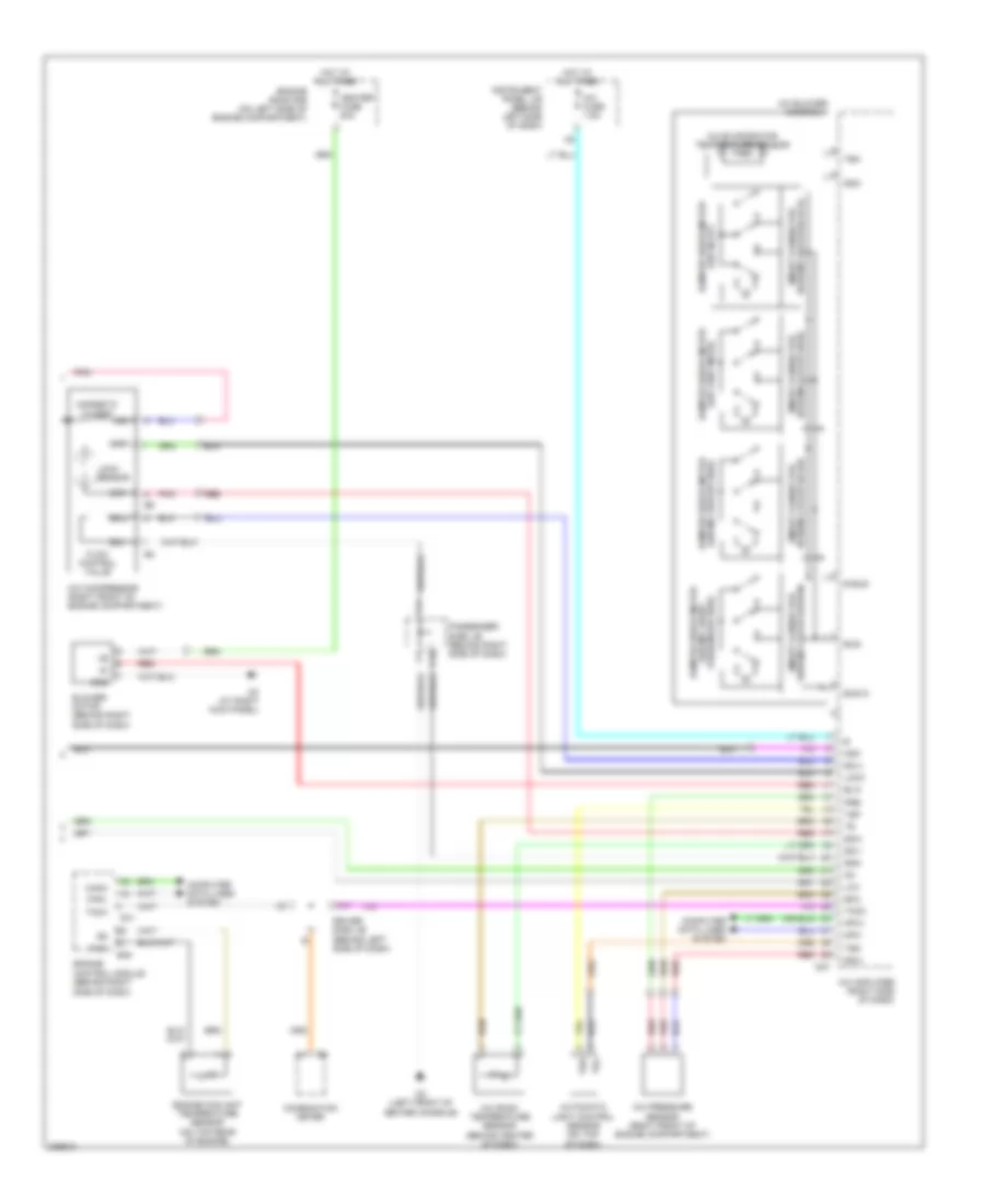
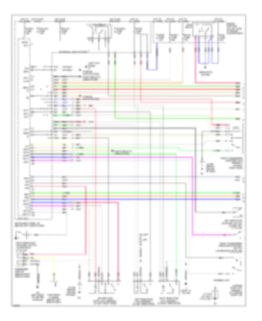
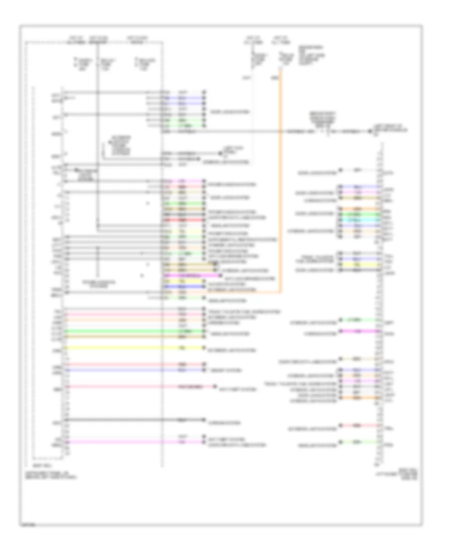
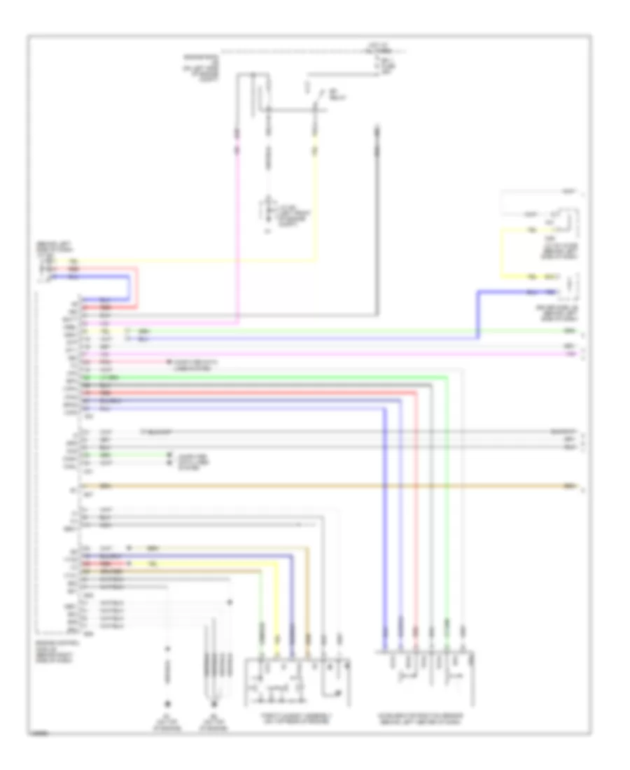
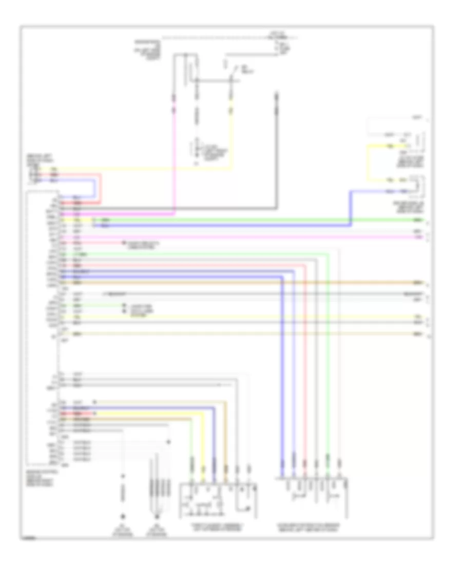
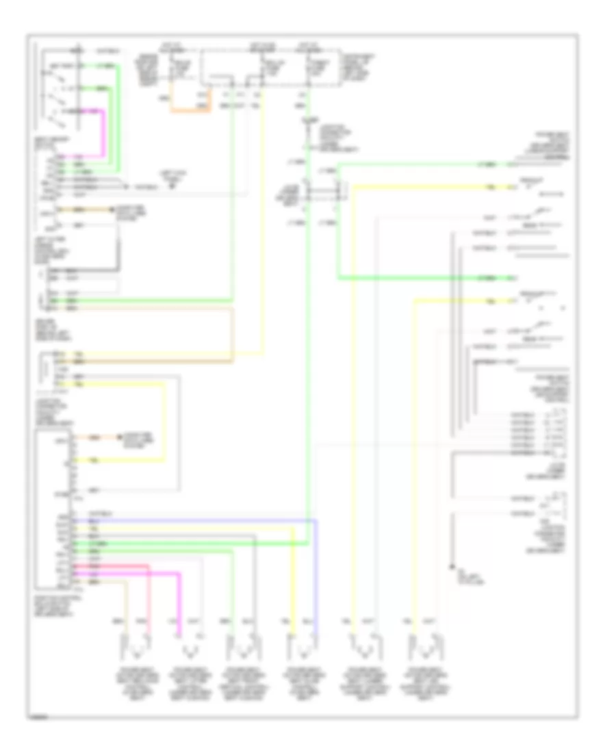
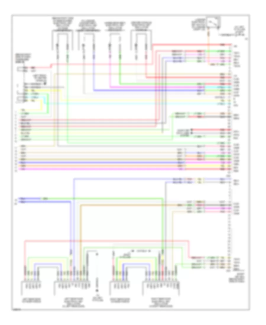
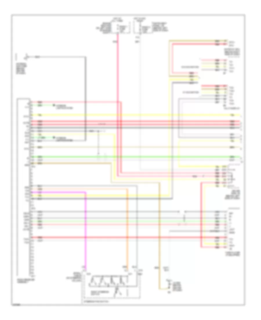
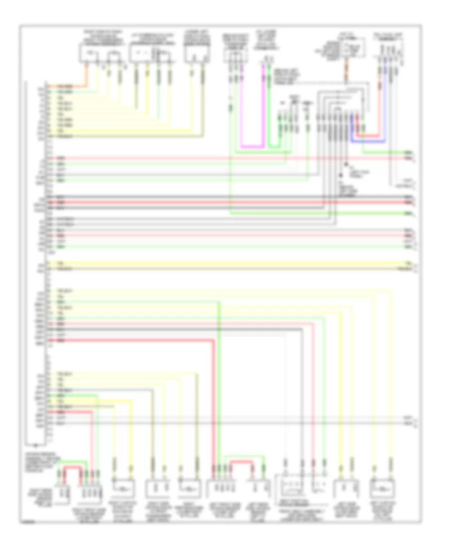
AIR CONDITIONING
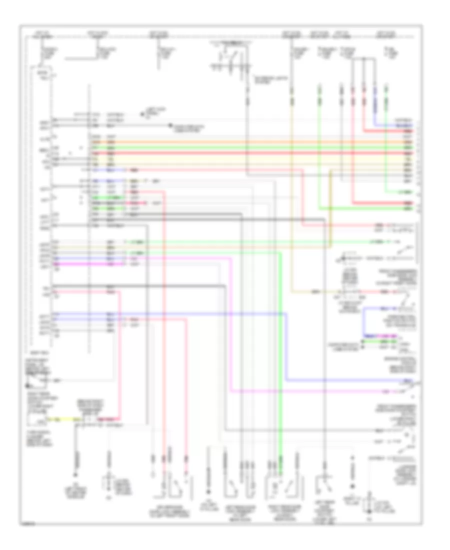
Automatic A/C Wiring Diagram (1 of 2) for Toyota Avalon XLS 2005
 https://portal-diagnostov.com/license.html
Automotive Electricians Portal FZCO
Automotive Electricians Portal FZCO
https://portal-diagnostov.com/license.html
https://portal-diagnostov.com/license.html
Automotive Electricians Portal FZCO
Automotive Electricians Portal FZCO
List of elements for Automatic A/C Wiring Diagram (1 of 2) for Toyota Avalon XLS 2005:
- (at left end of dash)
- (front of engine compartment) cooling fan ecu
- (ig 0-5v) a/d in
- +b1
- A/c comp fuse 7.5a
- A/c control assembly
- A41
- Ac1
- Adi1
- Ambient temperature sensor (behind grille)
- Auto
- B15
- Bean i/f
- C12
- Computer data lines system
- D46
- Driver side j/b (behind left side of dash)
- Eac
- Engine room j/b (on left side of engine compartment)
- Engine room r/b (on left side of engine compartment)
- F16
- Fan 1 relay
- Gnd
- Hot at all times
- Hot in on or start
- Htr fuse 7.5a
- Ig+
- Ill+
- Ill-
- Instrument panel j/b (behind left side of dash)
- J/c a41 & d46 (behind left side of dash)
- J/c a51 (left front of engine compt)
- J/c d53 (right front of engine compt)
- La/c
- Laut
- Led+
- Left steering switch
- Lrec
- Main fan motor
- Mg clt relay
- Micon
- Off
- Pil+
- Pil-
- Pnk
- Pse
- Rdi fan fuse 50a
- Red
- Right steering switch
- Spiral cable (on steering column)
- Steering wheel pad
- Sub fan motor
- Sw0
- Sw1
- Sw2
- Swa
- Swb
- Temp+
- Temp-
- Temperature control switch assembly
- Tx+
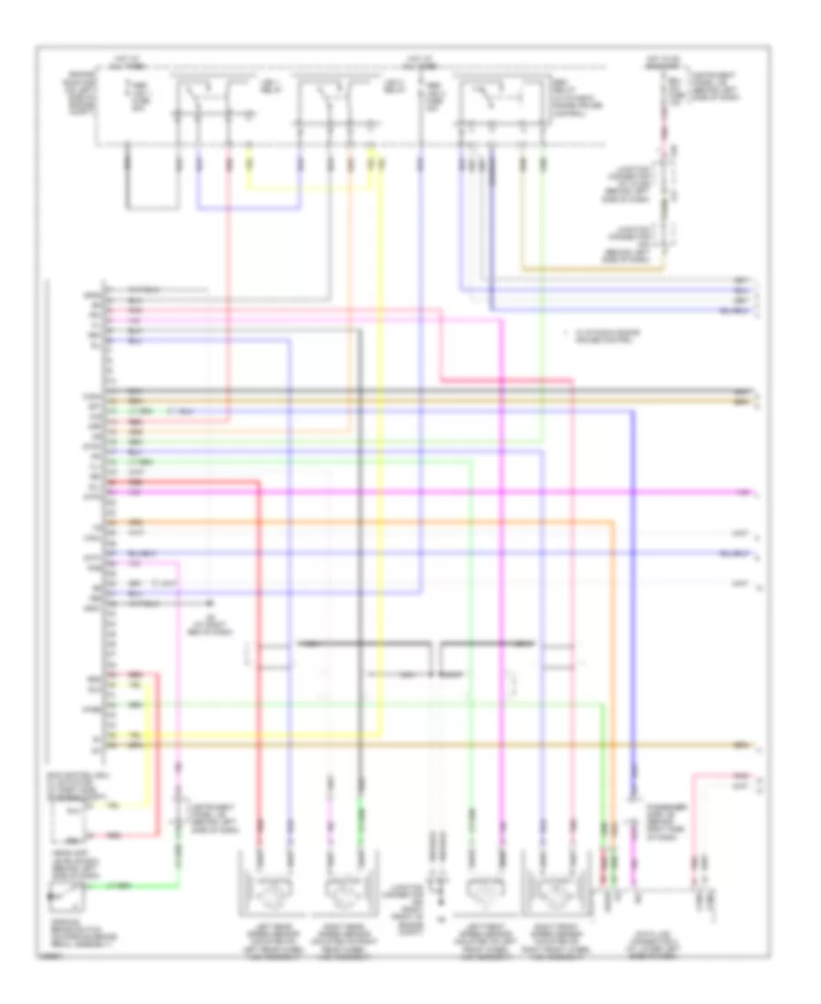
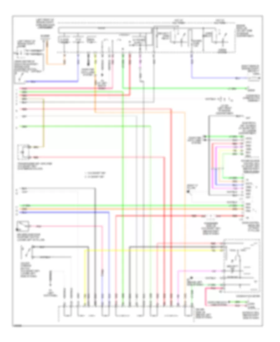
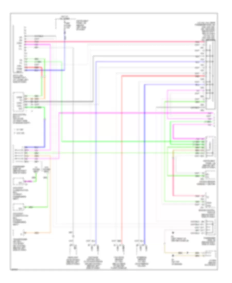
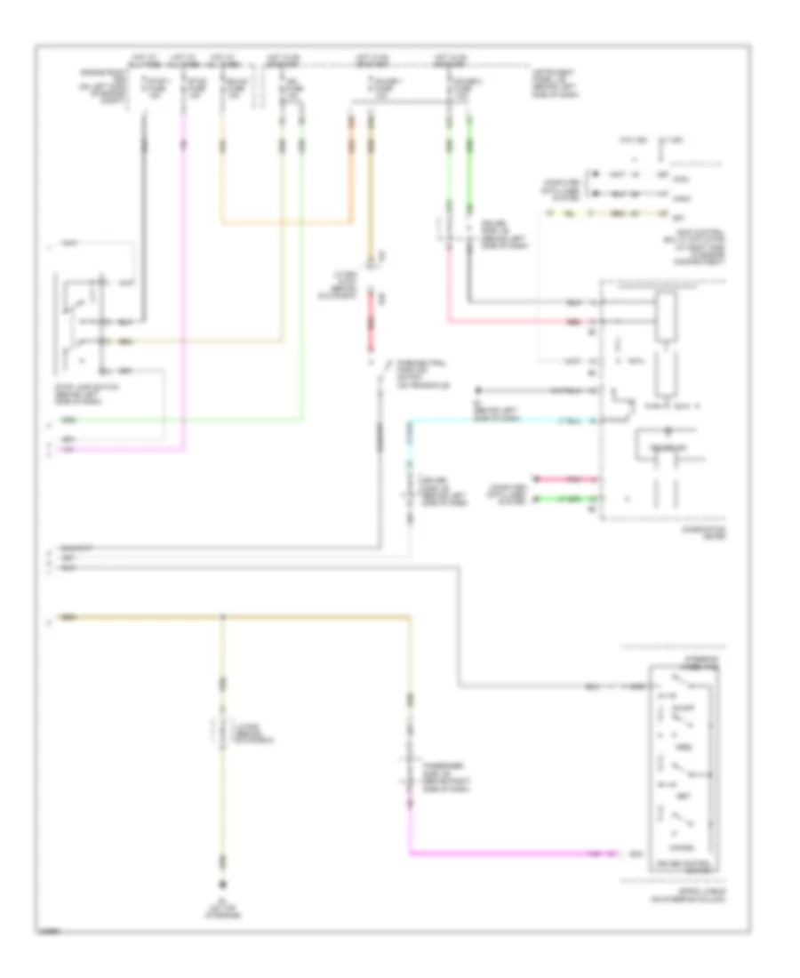
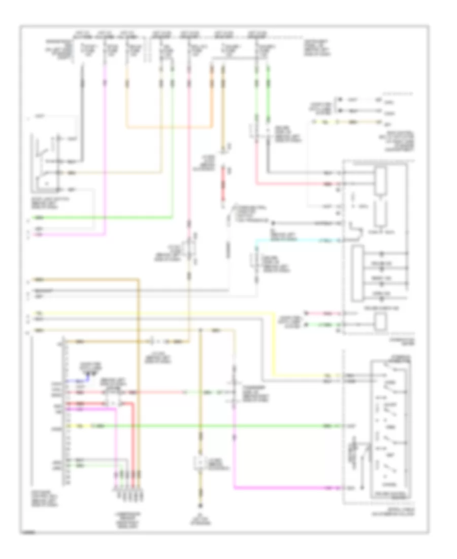
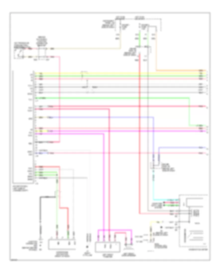
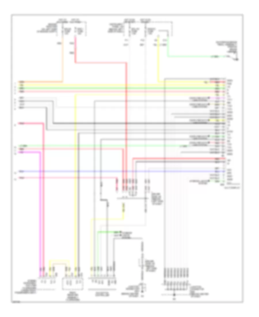
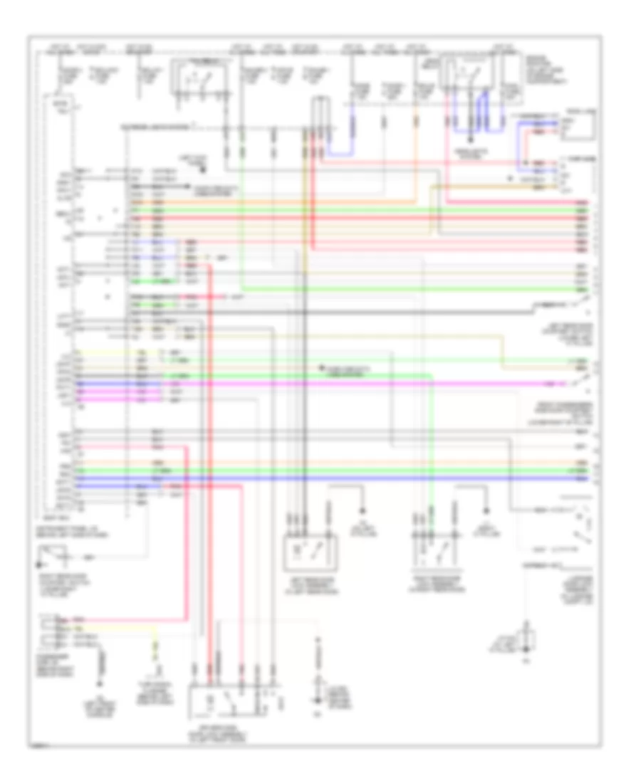
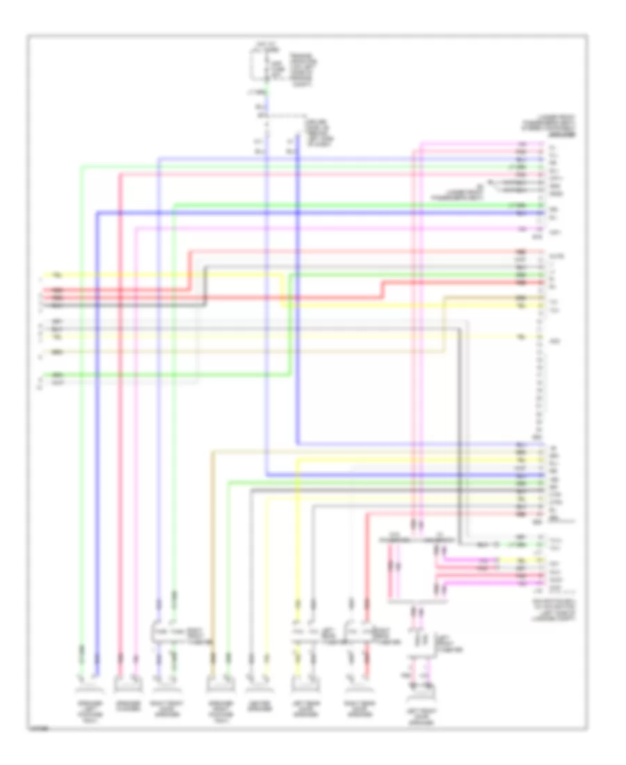
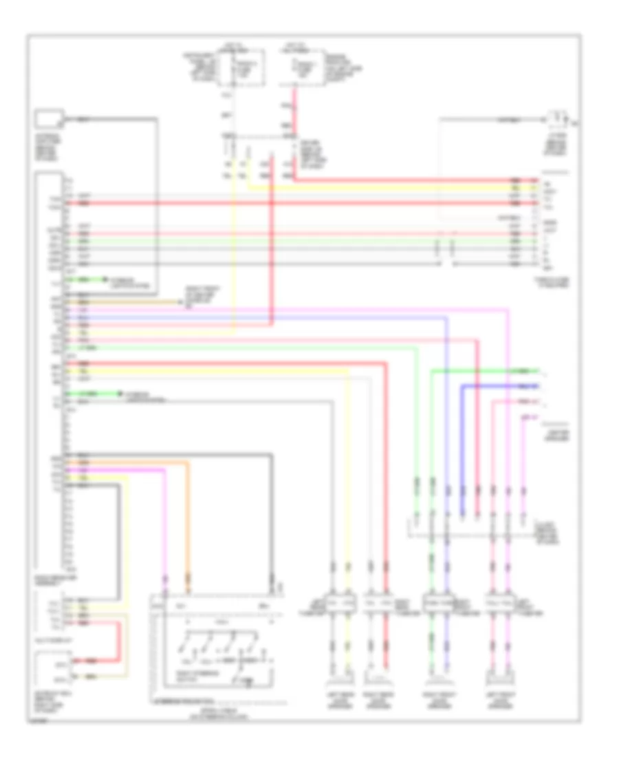
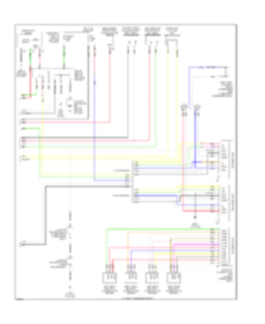
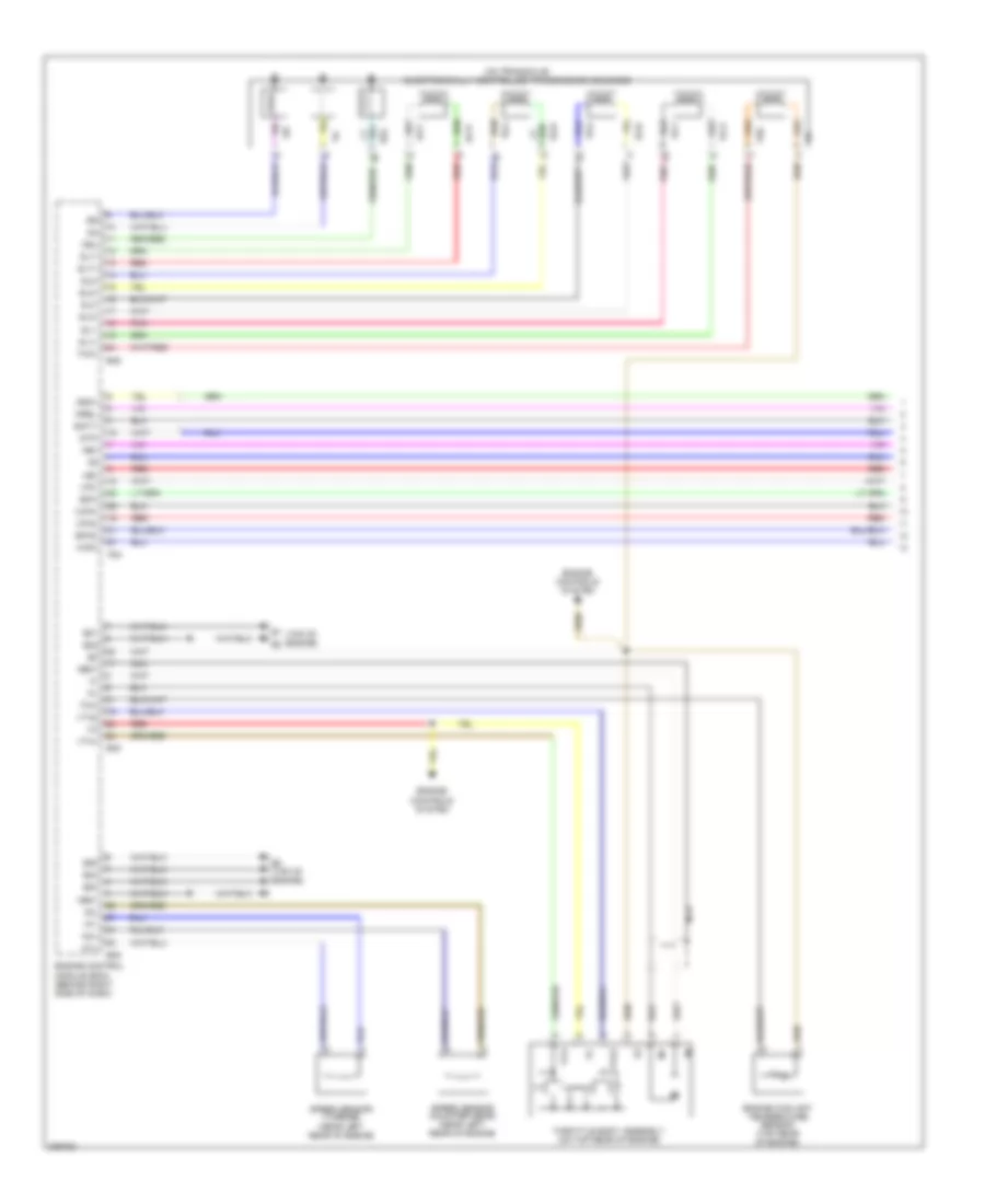
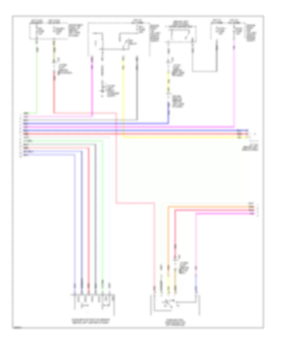
Automatic A/C Wiring Diagram (2 of 2) for Toyota Avalon XLS 2005
List of elements for Automatic A/C Wiring Diagram (2 of 2) for Toyota Avalon XLS 2005:
- (air inlet) damper servo motor
- (air mix front passenger side)
- A/c amplifier (right side of dash)
- A/c blower assembly
- A/c compressor (right front of engine compartment)
- A/c evaporator temperature sensor
- A/c fuse 7.5a
- A/c pressure sensor (right front of engine compartment)
- A/c room temperature sensor (behind center of dash)
- Automatic light control sensor (on top of dash)
- B bus
- B45
- Blower motor (behind right side of dash)
- Blw
- Bus
- Bus g
- C11
- C12
- Canh
- Canl
- Combination meter
- Computer data lines system
- D2 (left front of center console)
- D3 (at right kick panel)
- D37
- D41
- Damper servo motor
- Damper servo motor (air mix driver side)
- Damper servo motor (air vent mode)
- Driver side j/b (behind left side of dash)
- Engine control module (behind right side of dash)
- Engine coolant temperature sensor (on top rear of engine)
- Engine room r/b (on left side of engine compartment)
- Flow control value
- Gnd
- Heater fuse 50a
- Hot at all times
- Housing color (red) smart connector
- Ig+
- Instrument panel j/b (behind left side of dash)
- K17
- Lin1
- Lock
- Magnetic clutch
- Mg+
- Mgc
- Mpx+
- Mpx-
- Passenger side j/b (behind right side of dash)
- Pnk
- Pre
- Red
- S5-2
- Sensor
- Sg-1
- Sg-2
- Sg-3
- Sga
- Smart connector housing color (black)
- Smart connector housing color (green)
- Sol+
- Sol-
- Ssr+
- Ssr-
- Tach
- Taco
- Tea
- Thw
- Tsd
- Tsl
- Tsp
- Tsr
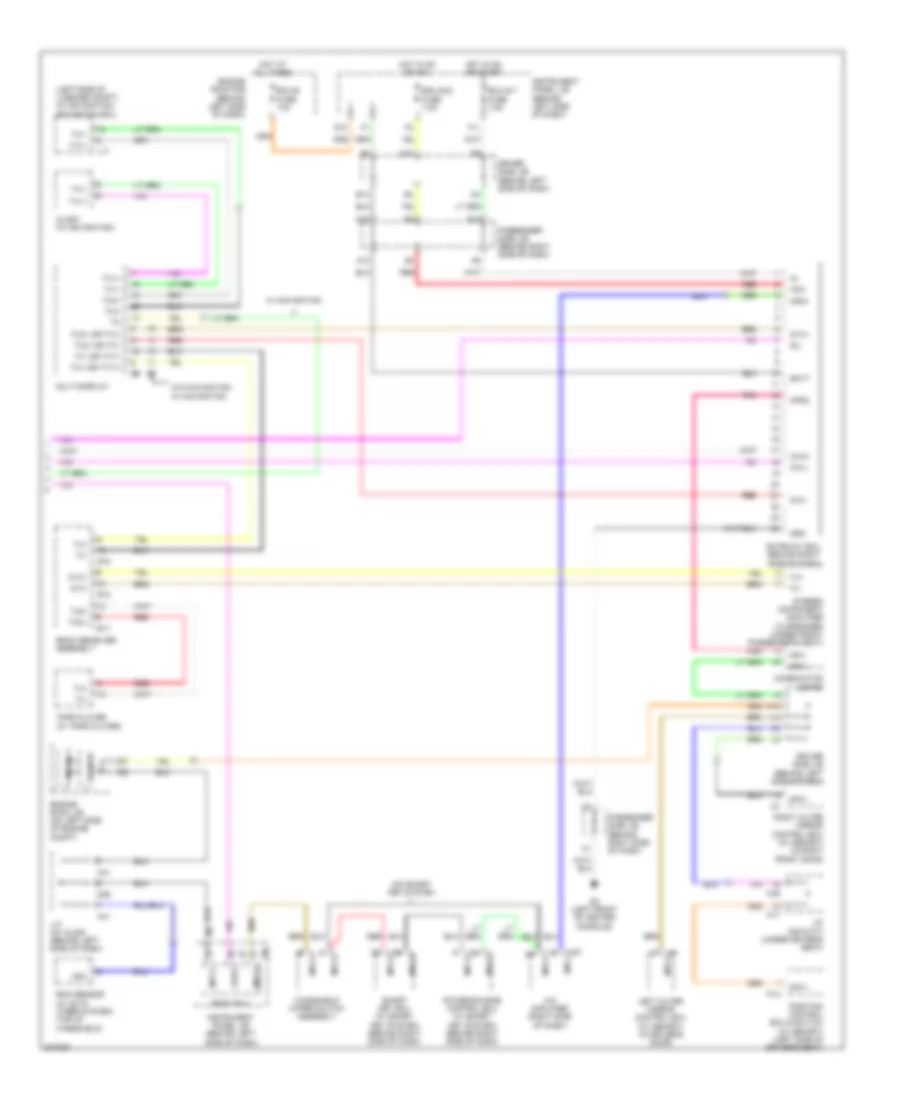
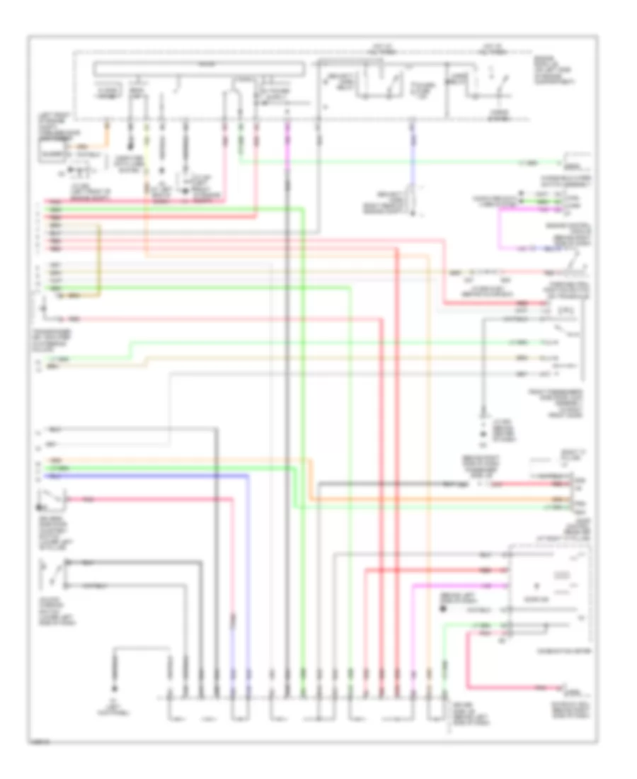
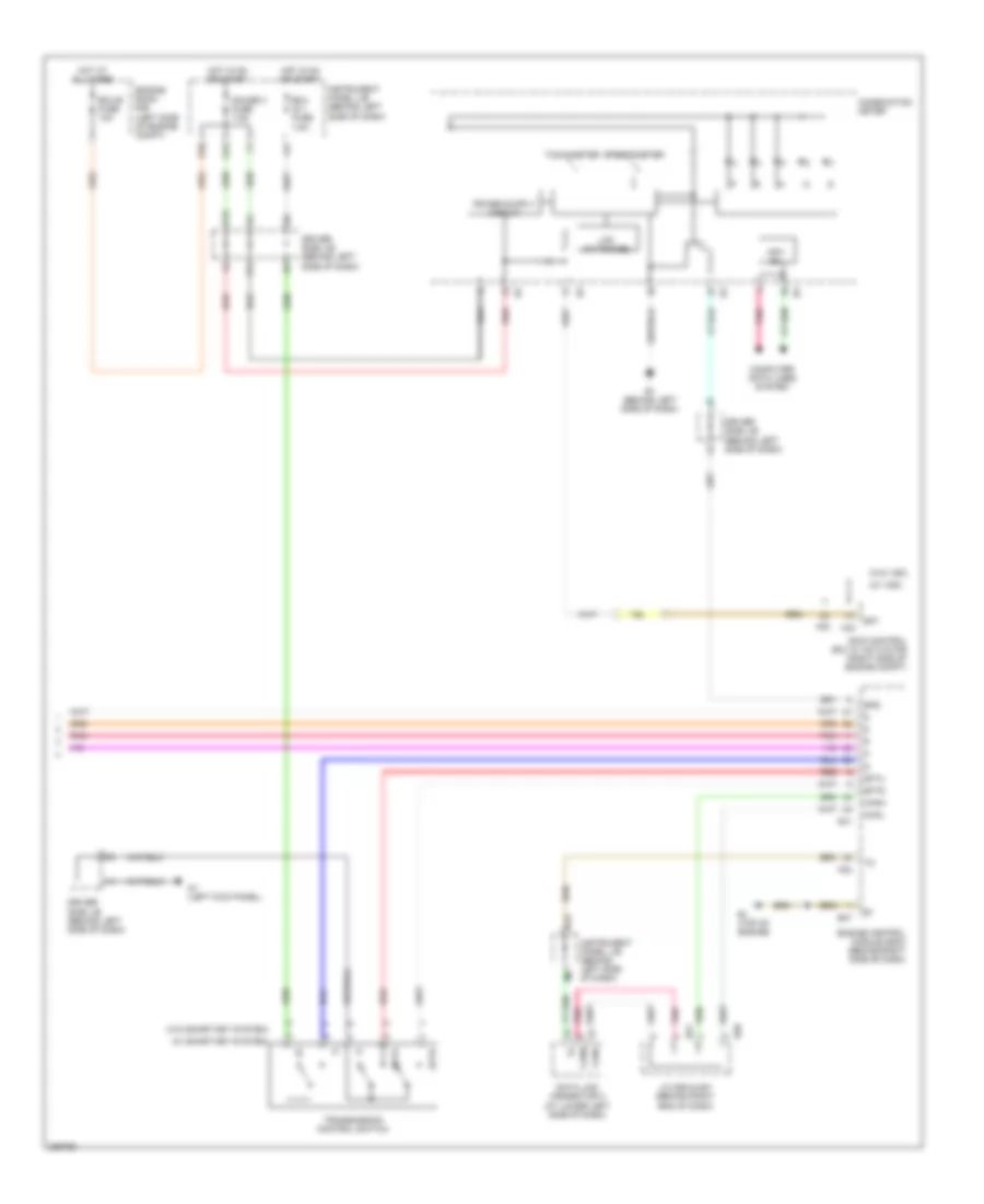
ANTI-LOCK BRAKES
Anti-lock Brakes Wiring Diagram, with Traction Control (1 of 2) for Toyota Avalon XLS 2005
List of elements for Anti-lock Brakes Wiring Diagram, with Traction Control (1 of 2) for Toyota Avalon XLS 2005:
- +bs
- A41
- A6 (at right end of dash)
- Abs/ vsc 1 fuse 50a
- Abs/ vsc 2 fuse 30a
- Brk relay (w/ dynamic radar cruise control)
- C14
- Canh
- Canl
- D/g
- D13
- D46
- Data link connector 3 (at lower left side of dash)
- Ecu ig 2 fuse 10a
- Engine room r/b (on left side of engine compt)
- F19
- Fl+
- Fl-
- Fr+
- Fr-
- Gnd1
- Gnd2
- Headlamp leveling ecu (behind left side of dash)
- Hot at all times
- Hot in on or start
- Ig1
- Instrument panel j/b (behind left side of dash)
- Junction connector a41 & d46 (behind left side of dash)
- Junction connector a42 (behind left side of dash)
- Junction connector a54 (right front of engine compt)
- Left front speed sensor (mounted on left front wheel hub assembly)
- Left rear speed sensor (mounted on left rear wheel hub assembly)
- Mrf
- Nca
- Parking brake switch (on parking brake pedal assembly)
- Passenger side j/b (behind right side of dash)
- Pkb
- Pnk
- Red
- Right front speed sensor (mounted on right front wheel hub assembly)
- Right rear speed sensor (mounted on right rear wheel hub assembly)
- Rl+
- Rl-
- Rlo
- Rr+
- Rr-
- Rro
- Skid control ecu w/ actuator (at right side of engine compt)
- Sp1
- Stp1
- Stp2
- Stpo
- Vsc 1 relay
- Vsc 2 relay
- W/ dynamic radar cruise control
- Wfse
Anti-lock Brakes Wiring Diagram, with Traction Control (2 of 2) for Toyota Avalon XLS 2005
List of elements for Anti-lock Brakes Wiring Diagram, with Traction Control (2 of 2) for Toyota Avalon XLS 2005:
- (left front of center console) d2
- (left front of engine comp) junction connector a52
- A44
- Abs
- B10
- B11
- B16
- Bat
- Brake
- Brake fluid level warning switch (on brake fluid reservoir)
- Buzzer
- C13
- Ca1h
- Ca1l
- Canh
- Canl
- Circuit
- Combination meter
- Computer data lines system
- D10
- D20
- D46
- D48
- D49
- D50
- D51
- D52
- Driver side j/b (behind left side of dash)
- E1 (behind left side of dash)
- E14
- E28
- Ecu ig 1 fuse 7.5a
- Ecu ig 2 fuse 10a
- Ecu-b fuse 10a
- Engine control module (behind right side of dash)
- Engine room j/b (on left side of engine compt)
- Engine room r/b (on left side of engine compt)
- Ess
- F11
- F15
- F19
- G12
- Gateway ecu (behind right side of dash)
- Gauge fuse 7.5a
- Gnd
- Hot at all times
- Hot in on or start
- I11
- Instrument panel j/b (behind left side of dash)
- Junction connector a41 & d46 (behind a41
- Junction connector a41 (behind left side of dash)
- Junction connector a42 (behind left side of dash)
- Junction connector a44, d48, d49, d50, d51, d52 & e28 (a44: near passenger side j/b) (d48,d49,d50,d51,d52 & e28: behind right end of dash)
- K15
- Left side of dash)
- Mpd1
- Mpd2
- Mpx +b
- Passenger side j/b (behind right side of dash)
- Pnk
- Radar fuse 7.5a
- Red
- Slip
- Speedometer
- Steering sensor (on steering column)
- Stop 1 fuse 15a
- Stop 2 fuse 7.5a
- Stop lamp switch (behind left side of dash)
- Vsc
- Vsc warning buzzer (behind left side of dash)
- W/ dynamic radar cruise control
- W/o dynamic radar cruise control
- Yaw rate sensor (below rear of center floor console)
Anti-lock Brakes Wiring Diagram, without Traction Control for Toyota Avalon XLS 2005
List of elements for Anti-lock Brakes Wiring Diagram, without Traction Control for Toyota Avalon XLS 2005:
- (a44: near passenger side j/b) (d48,d49,d50,d51,d52 & e28: behind right end of dash) junction connector a44, d50, d51, d52 & e28
- (at right end of dash) a6
- (behind right side of dash)
- (behind right side of dash) engine control module
- +bm
- +bs
- A41
- A44
- Abs ind
- Abs/ vsc 1 fuse 50a
- Abs/ vsc 2 fuse 30a
- Brake fluid level warning switch (right front of engine compt)
- Brake ind
- C13
- C14
- Ca1h
- Ca1l
- Canh
- Canl
- Combination meter
- Computer data lines system
- D/g
- D10
- D13
- D2 (left front of center console)
- D25
- D46
- D50
- D51
- Data link connector 3 (at lower left side of dash)
- Driver side j/b (behind left side of dash)
- E1 (behind left side of dash)
- E28
- Ecu ig 2 fuse 10a
- Ecu-b fuse 10a
- Engine room j/b (on left side of engine compt)
- Engine room r/b (on left side of engine compt)
- F15
- F19
- Fl+
- Fl-
- Fr+
- Fr-
- G12
- Gateway ecu
- Gauge fuse 7.5a
- Gnd1
- Gnd2
- Headlamp leveling ecu (behind left side of dash)
- Hot at all times
- Hot in on or start
- I11
- Ig1
- Instrument panel j/b (behind left side of dash)
- Instrument panel j/b (on left side of engine compt)
- Junction connector a41 & d46 (behind left side of dash)
- Junction connector a41 (behind left side of dash)
- Junction connector a42 (behind left side of dash)
- Junction connector a52 (engine compt left front of)
- Junction connector a54 (right front of engine compt)
- K15
- Left front speed sensor (mounted on left front wheel hub assembly)
- Left rear speed sensor (mounted on left rear wheel hub assembly)
- Mpd1
- Mpd2
- Mpx +b
- Nca
- Parking brake switch (on parking brake pedal assembly)
- Passenger side j/b (behind right side of dash)
- Pkb
- Pnk
- Red
- Right front speed sensor (mounted on right front wheel hub assembly)
- Right rear speed sensor (mounted on right rear wheel hub assembly)
- Rl+
- Rl-
- Rlo
- Rr+
- Rr-
- Rro
- Sil
- Skid control ecu w/ actuator (at right side of engine compt)
- Sp1
- Spdl
- Spdr
- Speedometer
- Stop 1 fuse 15a
- Stop fuse 7.5a
- Stop lamp switch (behind left side of dash)
- Stp
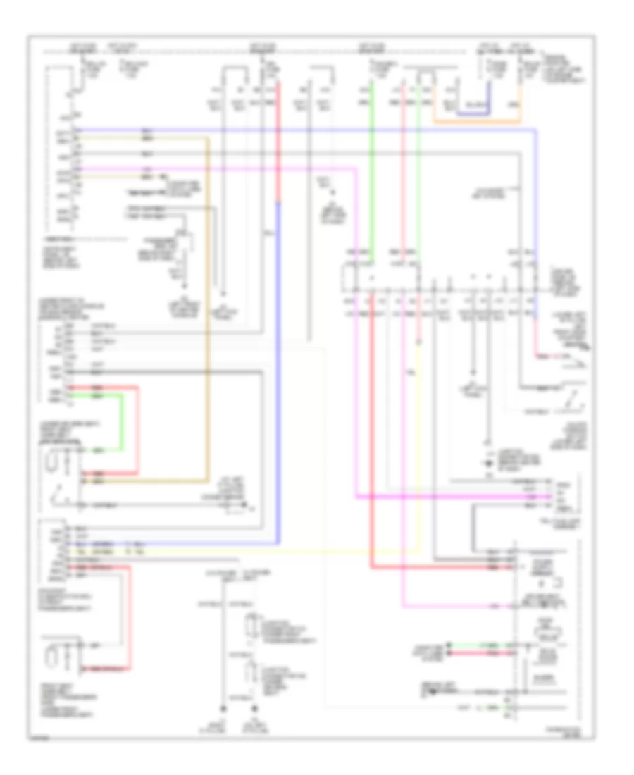
ANTI-THEFT
Forced Entry Wiring Diagram (1 of 2) for Toyota Avalon XLS 2005
List of elements for Forced Entry Wiring Diagram (1 of 2) for Toyota Avalon XLS 2005:
- (left kick panel) d1
- (on left "a" pillar) k3
- Acc
- Act+
- Act-
- Actd
- Altb
- B18
- Batb
- Becu
- Body ecu
- Computer data lines system
- D10
- D13
- D16
- D2 (left front of center console)
- Dcty
- Dome fuse 7.5a
- Door 1 fuse 25a
- Door 2 fuse 25a
- Driver's side door lock assembly (in left front door)
- Ecu-acc fuse 7.5a
- Ecu-b fuse 10a
- Ecu-ig 1 fuse 7.5a
- Engine room r/b (on left side of engine compartment)
- Exterior lights system
- F10
- F18
- Front passenger's side door courtesy switch (lower right "b" pillar)
- Front passenger's side door lock assembly (in right front door)
- G12
- Gauge 2 fuse 7.5a
- Gnd1
- Gnd2
- Haz
- Head relay
- Headlights system
- Hot at all times
- Hot in acc or on
- Hot in on or start
- I10
- Ile
- Ind
- Instrument panel j/b (behind left side of dash)
- Interior lights system
- J/c d53 (behind center of dash)
- J/c k34 (at left "c" pillar)
- K16
- Ksw
- L1 (right "c" pillar)
- L10
- Lcty
- Left rear door courtesy switch (lower left "c" pillar)
- Left rear door lock assembly (in left rear door)
- Lgcy
- Lswd
- Lswl
- Lswp
- Lswr
- Luggage door lock assembly (in luggage compt lid)
- M18
- Main fuse 40a
- Mpx-b fuse 7.5a
- Mpx1
- Mpx2
- P11
- Passenger side j/b (behind right side of dash)
- Pcty
- Pnk
- Prg
- Rcty
- Rda
- Red
- Right rear door courtesy switch (lower right "c" pillar)
- Right rear door lock assembly (in right rear door)
- Tail relay
- Tr+
- Trly
- Turn signal flasher (behind left side of dash)
- Ul2
- Ul3
Forced Entry Wiring Diagram (2 of 2) for Toyota Avalon XLS 2005
List of elements for Forced Entry Wiring Diagram (2 of 2) for Toyota Avalon XLS 2005:
- (left front of engine compt) j/c a52
- (left front of engine compt) wireless door lock buzzer
- (near center of radiator support) engine hood courtesy switch
- (right "c" pillar) l2
- (right rear of engine compt) security horn
- A3 (at left end of dash)
- Ant
- Asel
- Bean i/f
- Buzzer
- Combination meter
- Computer data lines system
- D1 (left kick panel)
- D10
- D20
- Data
- Door control receiver (at right "c" pillar)
- Door ind
- Driver side j/b (behind left side of dash)
- Driver's side door courtesy switch (lower left "b" pillar)
- E1 (behind left side of dash)
- E14
- Electrical key antenna (w/ smart key) (in luggage compartment)
- Engine room j/b (on left side of engine compartment)
- Gateway ecu (behind right side of dash)
- Gnd
- Head
- Horn relay
- Horns system
- Hot at all times
- I11
- J/c a51 (left front of engine compartment)
- K14
- K15
- K18
- K19
- L10
- L11
- L12
- L16
- L22
- Mi side i/f (+b)
- Micon
- Mpd1
- Mpd2
- Mpx1
- Mpx2
- P-i/p i/f
- Passenger side j/b (w/o smart key) (behind right side of dash)
- Pnk
- Power source control ecu (w/ smart key) (behind right side of dash)
- Prg
- Rco
- Rda
- Red
- Rssi
- S-horn fuse 7.5a
- Security horn relay
- Security ind
- Transponder key amplifier (w/o smart key) (in steering column)
- Unlock warning switch (w/o smart key) (lower left side of dash)
- W/ smart key
- W/o smart key
- Windshield wiper switch assembly
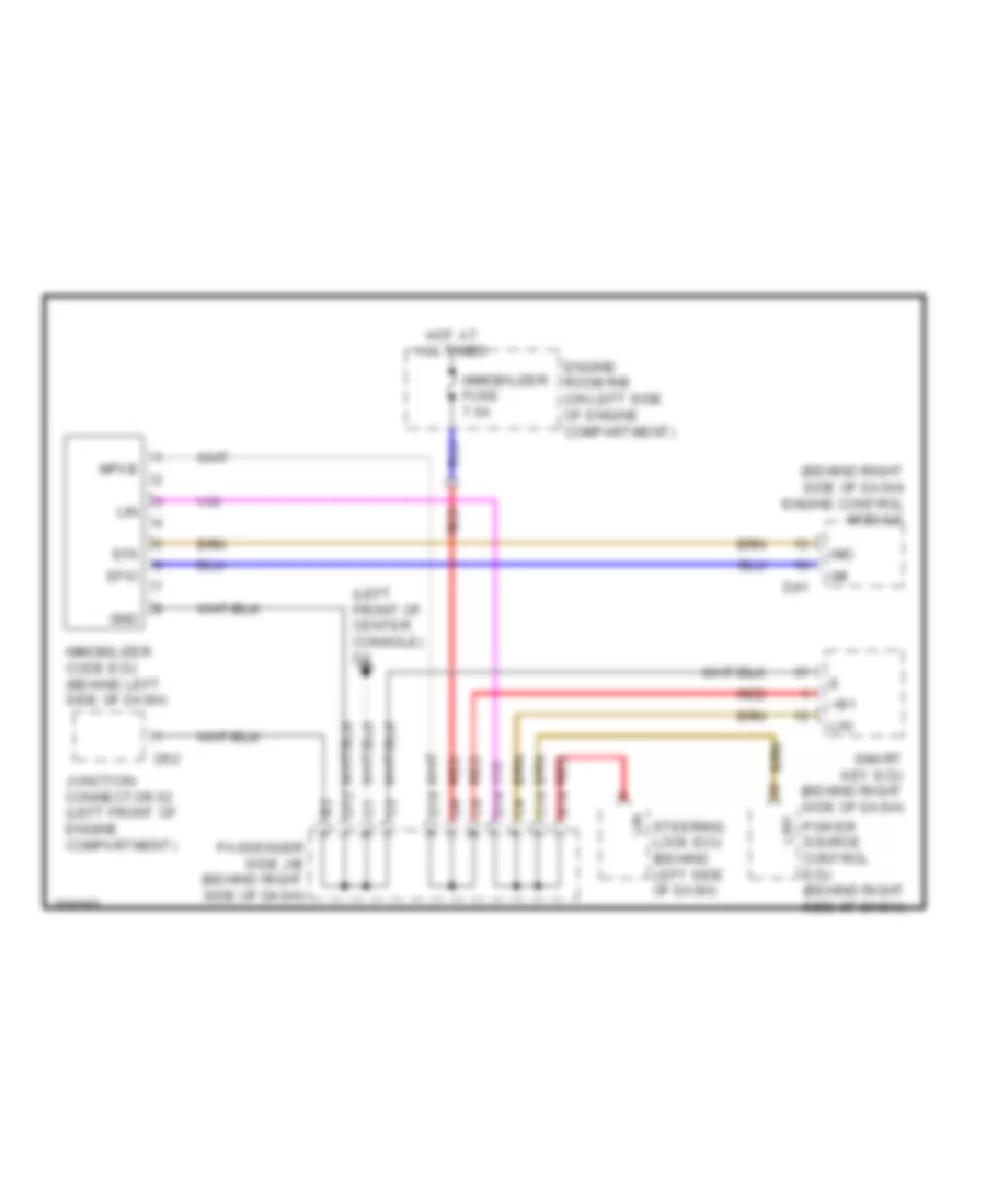
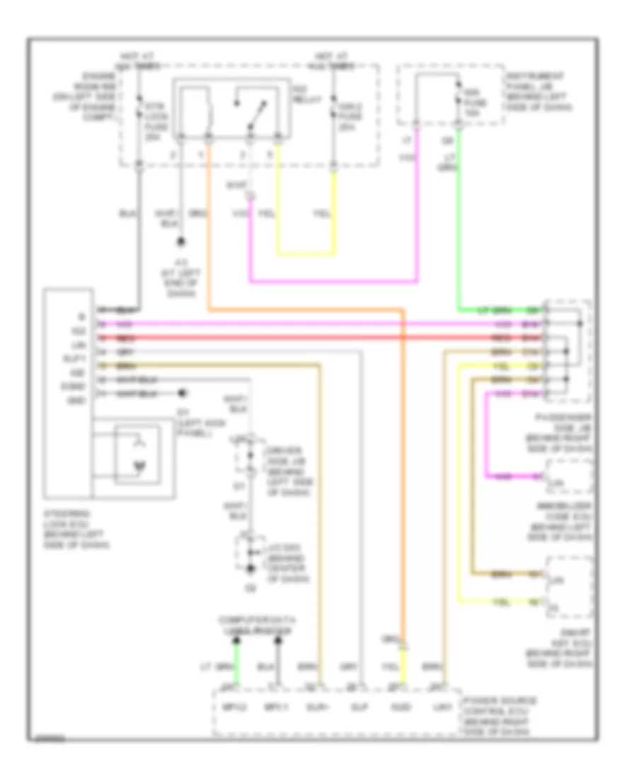
Immobilizer Wiring Diagram, with Smart Key System for Toyota Avalon XLS 2005
List of elements for Immobilizer Wiring Diagram, with Smart Key System for Toyota Avalon XLS 2005:
- (behind right side of dash) engine control module
- (left front of center console) d2
- +b1
- B14
- C14
- D12
- D14
- D18
- D41
- D52
- Efii
- Efio
- Engine room r/b (on left side of engine compartment)
- Gnd
- Hot at all times
- Imi
- Immobilizer code ecu (behind left side of dash)
- Immobilizer fuse 7.5a
- Imo
- Junction connector 52 (left front of engine compartment)
- Lin
- Lin1
- Mpxb
- Passenger side j/b (behind right side of dash)
- Power source control ecu (behind right side of dash)
- Red
- Smart key ecu (behind right side of dash)
- Steering lock ecu (behind left side of dash)
Immobilizer Wiring Diagram, without Smart Key System for Toyota Avalon XLS 2005
List of elements for Immobilizer Wiring Diagram, without Smart Key System for Toyota Avalon XLS 2005:
- (behind left side of dash) j/c a41
- (left kick panel) d1
- +b2
- A24
- Agnd
- Ant1
- Ant2
- B1 (on top of engine)
- B2 (on top of engine)
- Batt
- C13
- C18
- C19
- Code
- Combination meter
- Cty
- D10
- D13
- D41
- D45
- D46
- D47
- Data link connector 3 (at lower left side of dash)
- Driver side j/b (behind left side of dash)
- Driver's side door courtesy switch (lower left "b" pillar)
- E01
- E02
- E03
- E04
- E05
- E1 (behind left side of dash)
- Ecu-b fuse 10a
- Efi 1 fuse 25a
- Efi relay
- Efii
- Efio
- Engine control module (behind right side of dash)
- Engine room j/b (on left side of engine compartment)
- Engine room r/b (on left side of engine compartment)
- Gnd
- H10
- Hot at all times
- Hot in on or start
- I11
- Ign fuse 10a
- Igsw
- Imi
- Immobilizer fuse 7.5a
- Imo
- Ind
- Instrument panel j/b (behind left side of dash)
- J/c a51 (left front of engine compt)
- J/c d53 (right front of engine compartment)
- K12
- K16
- K21
- K22
- Key coil transponder
- Ksw
- L10
- L11
- Me01
- Mrel
- Passenger side j/b (behind right side of dash)
- Pnk
- Red
- Security ind
- Sil
- Transponder key amplifier (in steering column)
- Transponder key ecu (behind left side of dash)
- Txct
- Unlock warning switch (lower left side of dash)
- Vc5
BODY CONTROL MODULES
Body Control Modules Wiring Diagram for Toyota Avalon XLS 2005
List of elements for Body Control Modules Wiring Diagram for Toyota Avalon XLS 2005:
- (behind right side of dash) passenger side j/b
- (left front of center console) d2
- (left kick panel) d1
- Acan
- Acc
- Act+
- Act-
- Actd
- Altb
- Anti-lock brakes system
- Anti-theft system
- Batb
- Becu
- Body ecu
- Body ecu (attached to driver side j/b)
- C14
- Cltb
- Clte
- Clts
- Computer data lines system
- Cspt
- D10
- D16
- Dbkl
- Dcty
- Dcyl
- Door 1 fuse 25a
- Door 2 fuse 25a
- Door locks system
- Ecu-acc fuse 7.5a
- Ecu-b fuse 10a
- Ecu-ig 1 fuse 7.5a
- Engine room r/b (on left side of engine compt)
- Exterior lights & power windows systems
- Exterior lights system
- F10
- F11
- F18
- Ffgo
- Gbs
- Gnd1
- Gnd2
- Gsw
- Haz
- Headlights system
- Hot at all times
- Hot in acc or on
- Hot in on or start
- I10
- Ile
- Ind
- Instrument panel j/b (behind left side of dash)
- Interior lights system
- K12
- K15
- K16
- Ksw
- Lcty
- Lcyl
- Lgcy
- Lgyl
- Lswd
- Lswl
- Lswp
- Lswr
- Memory system
- Mirb
- Mire
- Mirrors system
- Mirs
- Mpx1
- Mpx2
- Navigation system
- Obd2
- P11
- Pcty
- Pcyl
- Pkb
- Pnk
- Power tops system
- Power windows system
- Power windows systems
- Prg
- Pws
- R10
- Rcty
- Rcyl
- Rda
- Red
- Tkul
- Tr+
- Trly
- Trnl
- Trnr
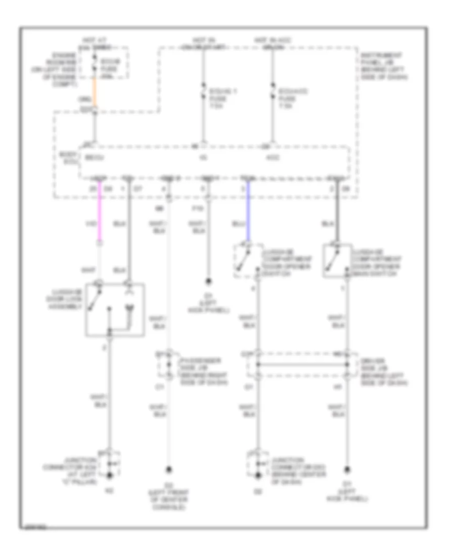
- Trunk, tailgate, fuel doors system
- Tsw
- Ul1
- Ul2
- Ul3
- Warning system
COMPUTER DATA LINES
Computer Data Lines Wiring Diagram (1 of 2) for Toyota Avalon XLS 2005
List of elements for Computer Data Lines Wiring Diagram (1 of 2) for Toyota Avalon XLS 2005:
- (j/c a43, a44: near passenger side j/b) (d48, d49, d50, d51, d52 & e28: behind right end of dash) j/c a43, a44, d48, d49, d50, d51, d52 & e28
- A24
- A43
- A44
- Air bag sensor assembly center
- B1 (on top of engine)
- B13
- Batt
- C13
- C17
- Canh
- Canl
- D/g
- D11
- D13
- D17
- D2 (left front of center console)
- D23
- D41
- D48
- D49
- D50
- D51
- D52
- Data link connector 3 (at lower left side of dash)
- Dia
- Distance control ecu (w/ dynamic radar cruise control) (behind left side of dash)
- E10
- E28
- Engine control module (behind right side of dash)
- H12
- Headlamp leveling ecu (behind left side of dash)
- Hot at all times
- Init
- Instrument panel j/b (behind left side of dash)
- J/c b49 (behind glove box)
- Lvl
- M12
- Obd fuse 7.5a
- Occupant classification ecu (in front passenger's seat)
- Passenger side j/b (behind right side of dash)
- Pnk
- Red
- Sil
- Skid control ecu w/ actuator (at right side of engine compt)
- Steering sensor (w/ vsc) (on steering column)
- Transponder key ecu (w/o smart key system) (behind left side of dash)
- W/ power seat
- W/ vsc
- W/o power seat
- W/o vsc
- Wfse
- Yaw rate sensor (w/ vsc) (below rear of center floor console)
Computer Data Lines Wiring Diagram (2 of 2) for Toyota Avalon XLS 2005
List of elements for Computer Data Lines Wiring Diagram (2 of 2) for Toyota Avalon XLS 2005:
- (left side of luggage compt) (w/ navigation) navigation ecu
- A/c amplifier (right side of dash)
- A10
- A41
- Acc
- Atx+
- Atx-
- B16
- Batt
- Beam i/f
- Body ecu
- Ca1h
- Ca1l
- Clock (w/ navigation)
- Combination meter
- D10
- D18
- D2 (left front of center console)
- D20
- D37
- D46
- Driver side j/b (behind left side of dash)
- E12
- E14
- E15
- E17
- Ecu-acc fuse 7.5a
- Ecu-b fuse 10a
- Ecu-ig 1 fuse 7.5a
- Engine room j/b (on left side of engine compt)
- Engine room r/b (behind left side of dash)
- F11
- Gateway ecu (behind right side of dash)
- Gnd
- Gtx+
- Gtx-
- Hot at all times
- Hot in on or acc
- Hot in on or start
- Instrument panel j/b (behind left side of dash)
- J/c a41 & d46 (behind left side of dash)
- J/c k35 & p17 (under driver's seat)
- K14
- K35
- L14
- L17
- Left outer mirror control ecu (w/ memory) (in driver's door)
- Micon
- Mpd1
- Mpd2
- Mpx
- Mpx+
- Mpx-
- Mpx1
- Mpx2
- Multi-display
- Obd2
- P13
- P17
- Passenger side j/b (behind right side of dash)
- Pnk
- Position control ecu & switch (w/ memory) (left side of driver's seat)
- Power source control ecu (w/ smart key system) (behind right side of dash)
- Radio receiver assembly
- Rain sensor (w/ auto wiper system) (top of windshield)
- Red
- Right outer mirror control ecu (w/ memory) (in right front door)
- Sil
- Smart key ecu (w/ smart key system) (behind right side of dash)
- Stereo component amplifier (12 speaker) (under front passenger's seat)
- Tape player (w/ tape player)
- Tx+
- Tx+ (or tx1+)
- Tx+1
- Tx-
- Tx- (or tx1-)
- Tx-1
- Tx1+
- Tx1-
- Tx2+ (or tx+)
- Tx2- (or tx-)
- Tx4+
- Tx4-
- Txm+
- Txm-
- W/ navigation
- W/o navigation w/ navigation
- W/o smart key system
- Windshield wiper switch assembly
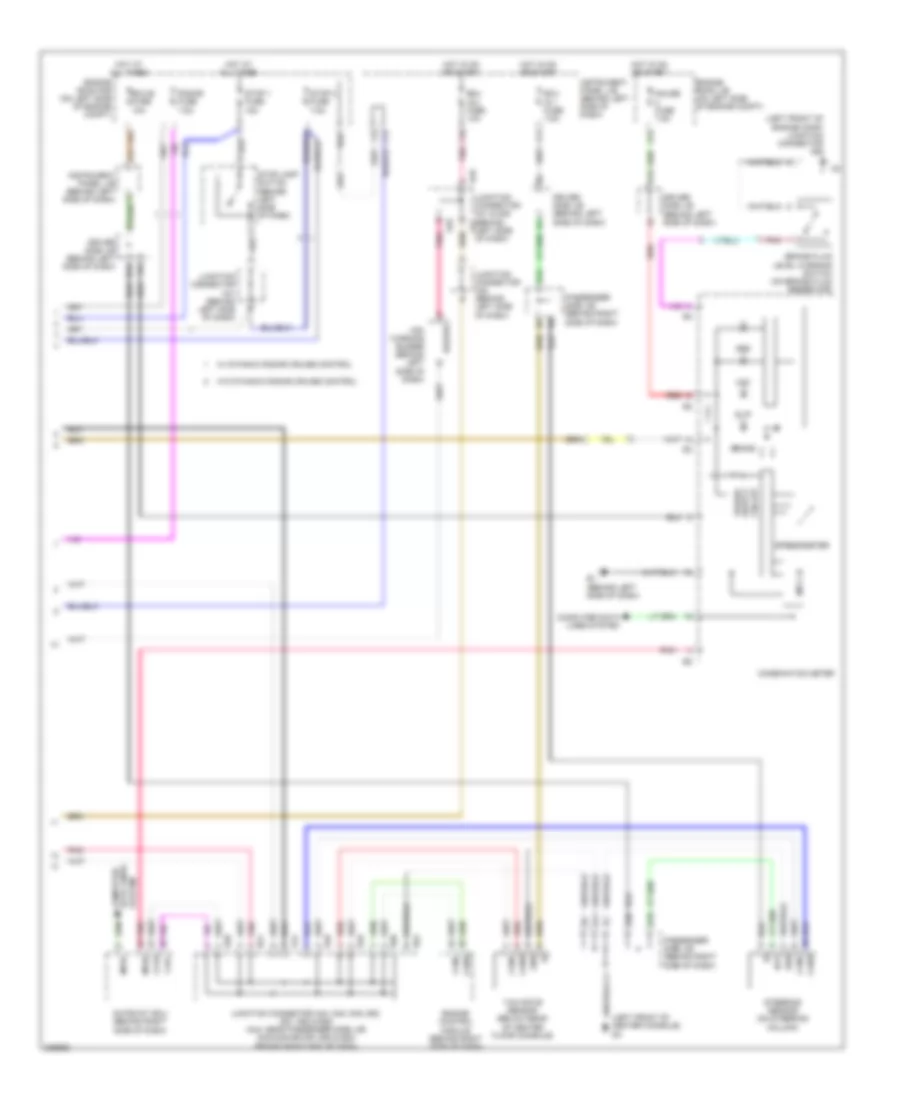
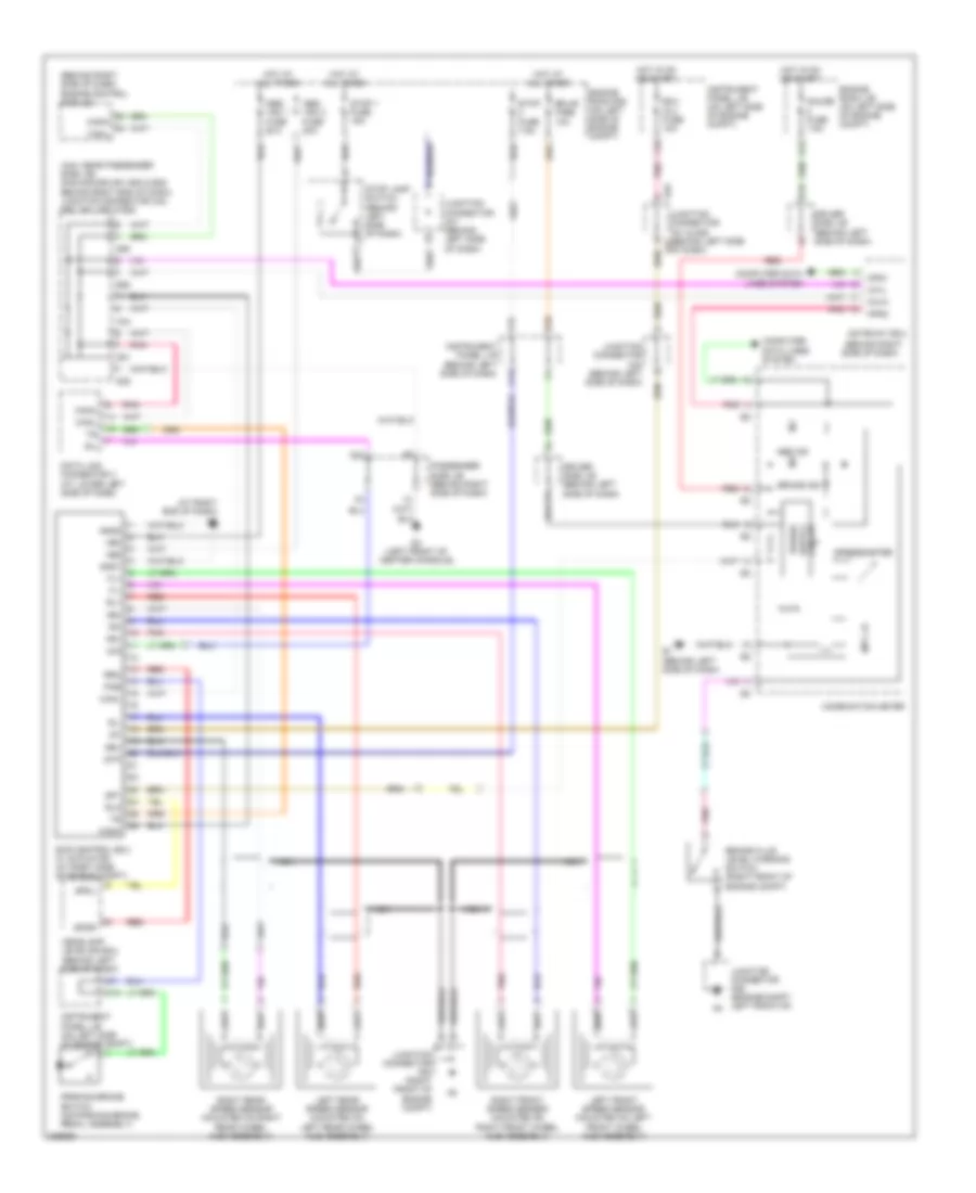
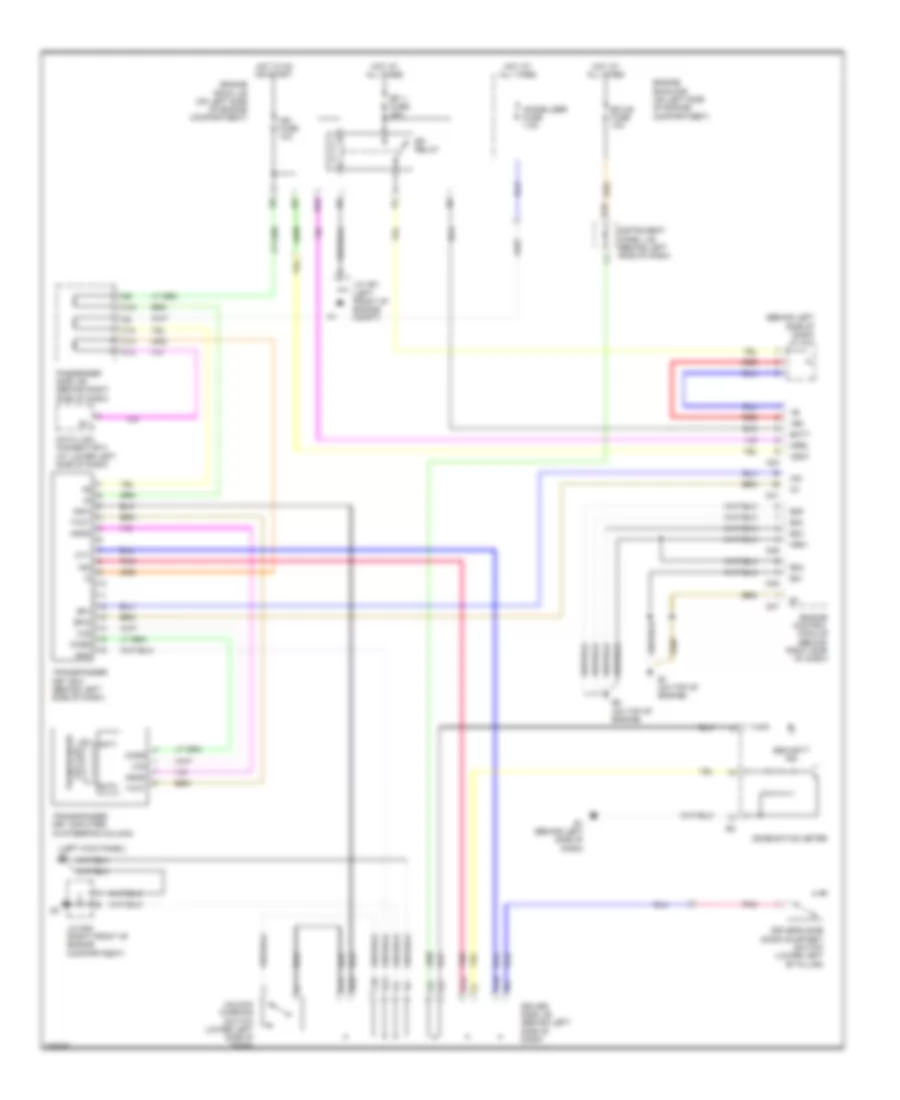
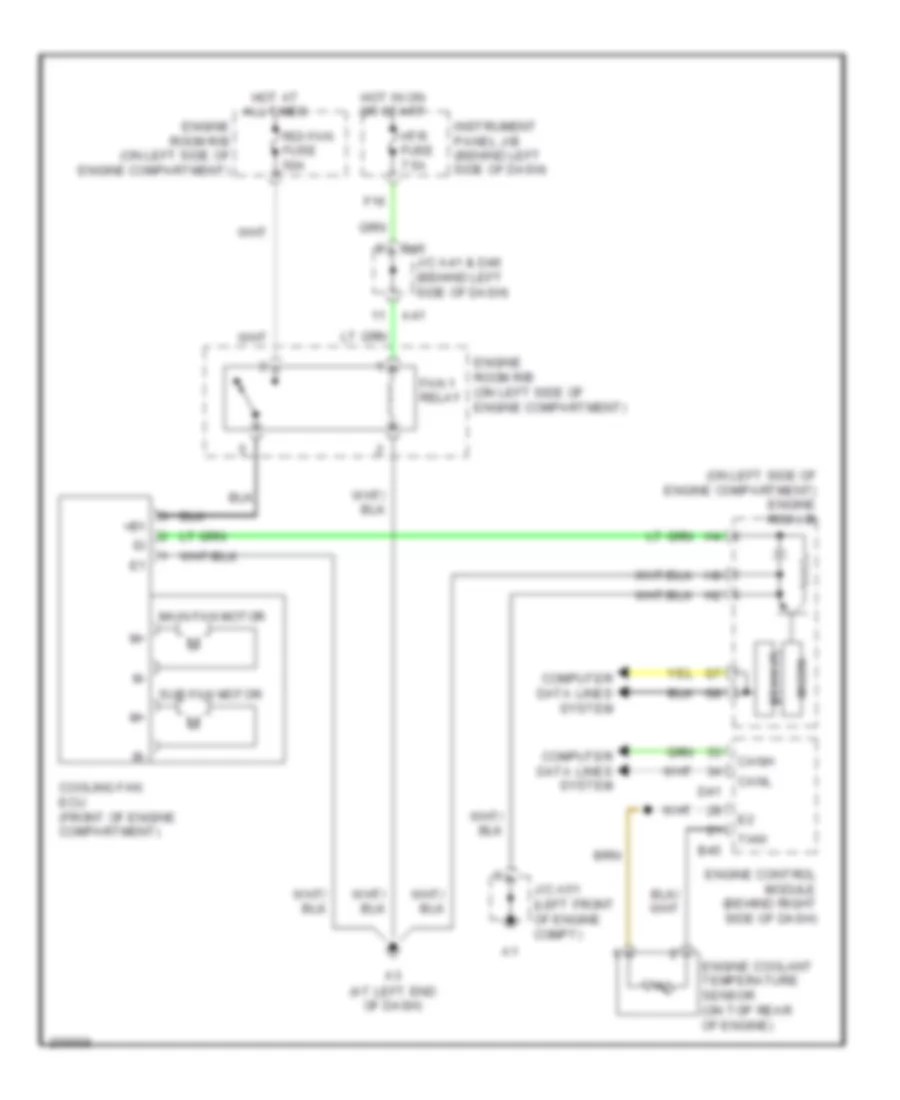
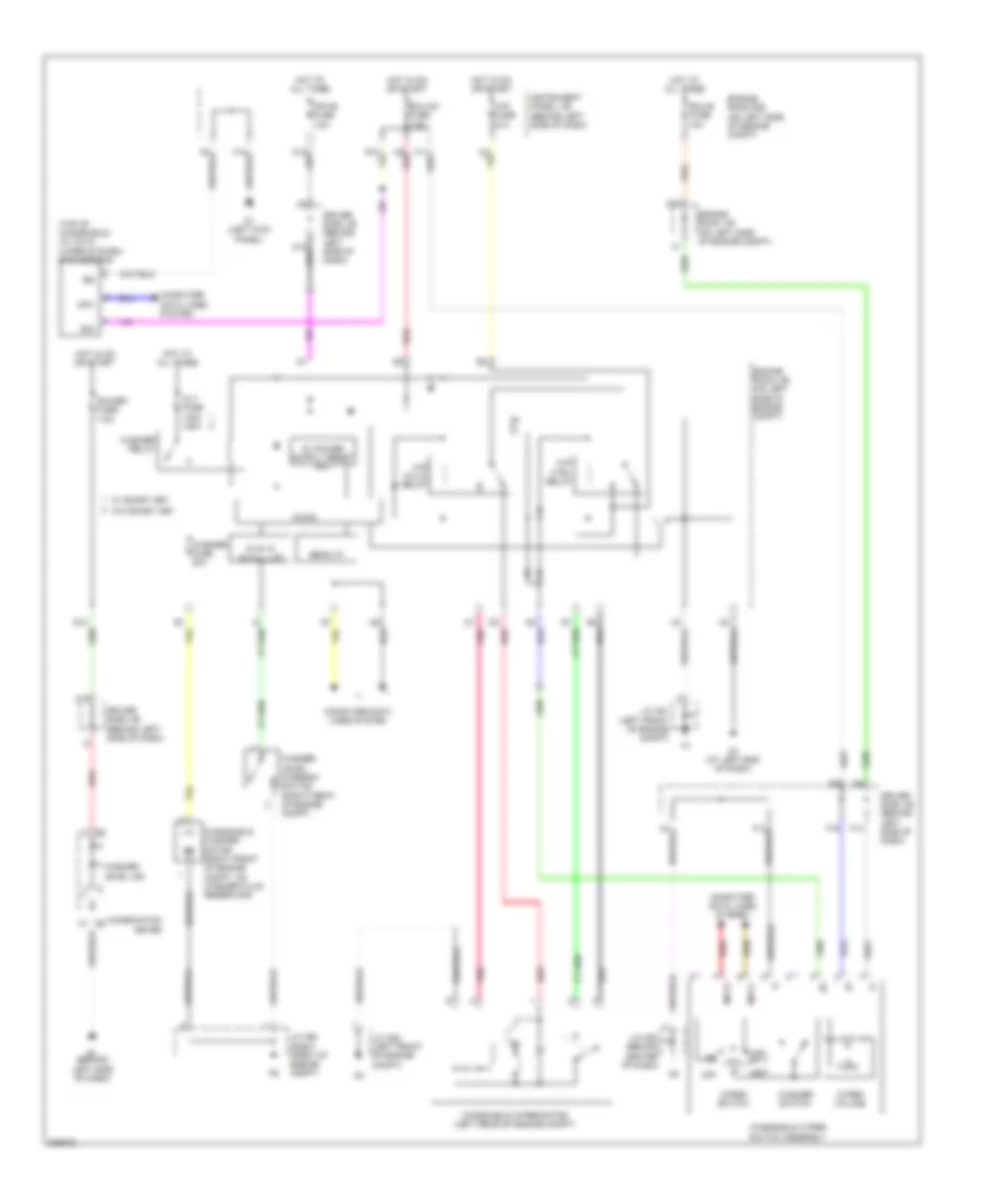
COOLING FAN
Cooling Fan Wiring Diagram for Toyota Avalon XLS 2005
List of elements for Cooling Fan Wiring Diagram for Toyota Avalon XLS 2005:
- (at left end of dash)
- (on left side of engine compartment) engine rom j/b
- +b1
- A41
- B45
- Bean i/f
- Canh
- Canl
- Computer data lines system
- Cooling fan ecu (front of engine compartment)
- D41
- D46
- Engine control module (behind right side of dash)
- Engine coolant temperature sensor (on top rear of engine)
- Engine room r/b (on left side of engine compartment)
- F16
- Fan 1 relay
- Hot at all times
- Hot in on or start
- Htr fuse 7.5a
- Instrument panel j/b (behind left side of dash)
- J/c a41 & d46 (behind left side of dash)
- J/c a51 (left front of engine compt)
- Main fan motor
- Micon
- Rdi fan fuse 50a
- Sub fan motor
- Thw
CRUISE CONTROL
Cruise Control Wiring Diagram (1 of 2) for Toyota Avalon XLS 2005
List of elements for Cruise Control Wiring Diagram (1 of 2) for Toyota Avalon XLS 2005:
- (behind left side of dash) j/c a41
- +b2
- +bm
- A24
- A41
- Accelerator position sensor (behind left center of dash)
- B1 (on top of engine)
- B2 (on top of engine)
- B45
- B46
- B47
- Batt
- Canh
- Canl
- Ccs
- Computer data lines system
- D41
- D46
- Driver side j/b (behind left side of dash)
- E01
- E02
- E03
- E04
- E05
- E10
- Efi 1 fuse 25a
- Efi relay
- Engine control module (behind right side of dash)
- Engine room j/b (on left side of engine compt)
- Epa
- Epa2
- F20
- Geo1
- H10
- Hot at all times
- Igsw
- J/c a41 & d46 (behind left side of dash)
- J/c a51 (left front of engine compt)
- Me01
- Mrel
- Nca
- Pnk
- Red
- Spd
- St1-
- Stp
- Throttle body assembly (on top rear of engine)
- Vcp2
- Vcpa
- Vpa
- Vpa2
- Vta
- Vta1
- Vta2
Cruise Control Wiring Diagram (2 of 2) for Toyota Avalon XLS 2005
List of elements for Cruise Control Wiring Diagram (2 of 2) for Toyota Avalon XLS 2005:
- +res
- -set
- B1 (on top of engine)
- B48
- C17
- Cancel
- Canh
- Canl
- Ccs
- Combination meter
- Computer data lines system
- Cruise control switch
- Cruise ind
- D10
- D47
- Driver side j/b (behind left side of dash)
- E1 (behind left side of dash)
- Ecc
- Ecu-b fuse 10a
- Engine room r/b (on left side of engine compt)
- Etcs fuse 10a
- G12
- Gauge 1 fuse 10a
- Gauge 2 fuse 7.5a
- H16
- Hot at all times
- Hot in on or start
- I11
- Ign fuse 10a
- Instrument panel j/b (behind left side of dash)
- J/c b48 & d47 (behind glove box)
- J/c b49 (behind glove box)
- K15
- On-off
- Park/neutral position switch (on transaxle)
- Passenger
- Pnk
- Red
- Side j/b (behind right side of dash)
- Skid control ecu w/ actuator (at right side of engine compartment)
- Sp1
- Spiral cable (on steering column)
- Steering wheel pad
- Stop 1 fuse 15a
- Stop lamp switch (behind left side of dash)
- W/ vsc
- W/o vsc
Dynamic Laser Cruise Control Wiring Diagram (1 of 2) for Toyota Avalon XLS 2005
List of elements for Dynamic Laser Cruise Control Wiring Diagram (1 of 2) for Toyota Avalon XLS 2005:
- (behind left side of dash) j/c a41
- +b2
- +bm
- A24
- A41
- Accelerator position sensor (behind left center of dash)
- B1 (on top of engine)
- B2 (on top of engine)
- B45
- B46
- B47
- Batt
- Canh
- Canl
- Cchg
- Ccs
- Computer data lines system
- D41
- D46
- Driver side j/b (behind left side of dash)
- E01
- E02
- E03
- E04
- E05
- E10
- Efi 1 fuse 25a
- Efi relay
- Engine control module (behind right side of dash)
- Engine room j/b (on left side of engine compt)
- Epa
- Epa2
- F20
- Geo1
- H10
- Hot at all times
- Igsw
- J/c a41 & d46 (behind left side of dash)
- J/c a51 (left front of engine compt)
- Lgnd
- Me01
- Mrel
- Nca
- Pnk
- Red
- Spd
- St1
- Stp
- Throttle body assembly (on top rear of engine)
- Vcp2
- Vcpa
- Vpa
- Vpa2
- Vta
- Vta1
- Vta2
Dynamic Laser Cruise Control Wiring Diagram (2 of 2) for Toyota Avalon XLS 2005
List of elements for Dynamic Laser Cruise Control Wiring Diagram (2 of 2) for Toyota Avalon XLS 2005:
- (behind left side of dash) j/c a42
- +res
- -set
- A41
- B1 (on top of engine)
- B48
- C17
- Cancel
- Canh
- Canl
- Ccs
- Combination meter
- Computer data lines system
- Control switch distance
- Cruise check ind
- Cruise control switch
- Cruise ind
- D10
- D46
- D47
- Dist
- Distance control ecu (behind left side of dash)
- Driver side j/b (behind left side of dash)
- E1 (behind left side of dash)
- Ecc
- Ecu ig 2 fuse 10a
- Ecu-b fuse 10a
- Engine room r/b (on left side of engine compt)
- Etcs fuse 10a
- F19
- G12
- Gauge 1 fuse 10a
- Gauge 2 fuse 7.5a
- Gnd
- H16
- Hot at all times
- Hot in on or start
- I11
- Igb
- Ign fuse 7.5a
- Instrument panel j/b (behind left side of dash)
- J/c a41 & d46 (behind left side of dash)
- J/c a42 (behind left side of dash)
- J/c b48 & d47 (behind glove box)
- J/c b49 (behind glove box)
- K15
- Laser radar sensor (near right headlamp)
- Lgnd
- Lrdd
- Lrrd
- Mode
- Norm ind
- On-off
- Park/neutral position switch (on transaxle)
- Passenger
- Pnk
- R/n
- Ready ind
- Red
- Sgnd
- Side j/b (behind right side of dash)
- Skid control ecu w/ actuator (at right side of engine compartment)
- Sp1
- Spiral cable (on steering column)
- Steering wheel pad
- Stop 1 fuse 10a
- Stop light switch (behind left side of dash)
DEFOGGERS
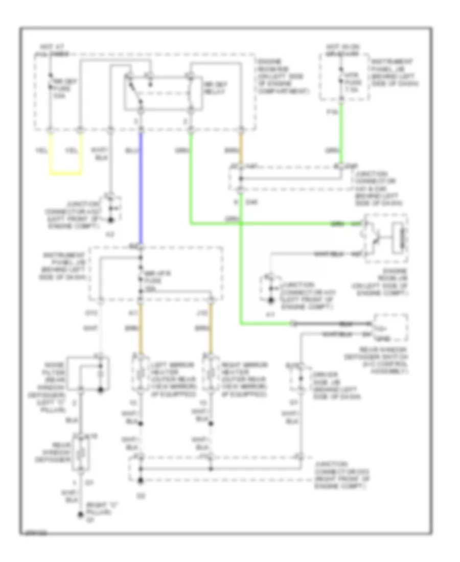
Rear Defogger & Heated Mirrors Wiring Diagram for Toyota Avalon XLS 2005
List of elements for Rear Defogger & Heated Mirrors Wiring Diagram for Toyota Avalon XLS 2005:
- (right "c" pillar) q1
- A41
- B15
- D46
- Driver side j/b (behind left side of dash)
- Engine room j/b (on left side of engine compt)
- Engine room r/b (on left side of engine compartment)
- F16
- Gnd
- Hot at all times
- Hot in on or start
- Htr fuse 7.5a
- Ig+
- Instrument panel j/b (behind left side of dash)
- J12
- Junction connector a41 & d46 (behind left side of dash)
- Junction connector a51 (left front of engine compt)
- Junction connector a52 (left front of engine compt)
- Junction connector d53 (right front of engine compt)
- K19
- Left mirror heater (outer rear view mirror) (if equipped)
- Micon
- Mir htr fuse 10a
- Noise filter (rear window defogger) (left "c" pillar)
- O13
- Rear window defogger
- Rear window defogger switch (a/c control assembly)
- Right mirror heater (outer rear view mirror) (if equipped)
- Rr def fuse 50a
- Rr def relay
ENGINE PERFORMANCE
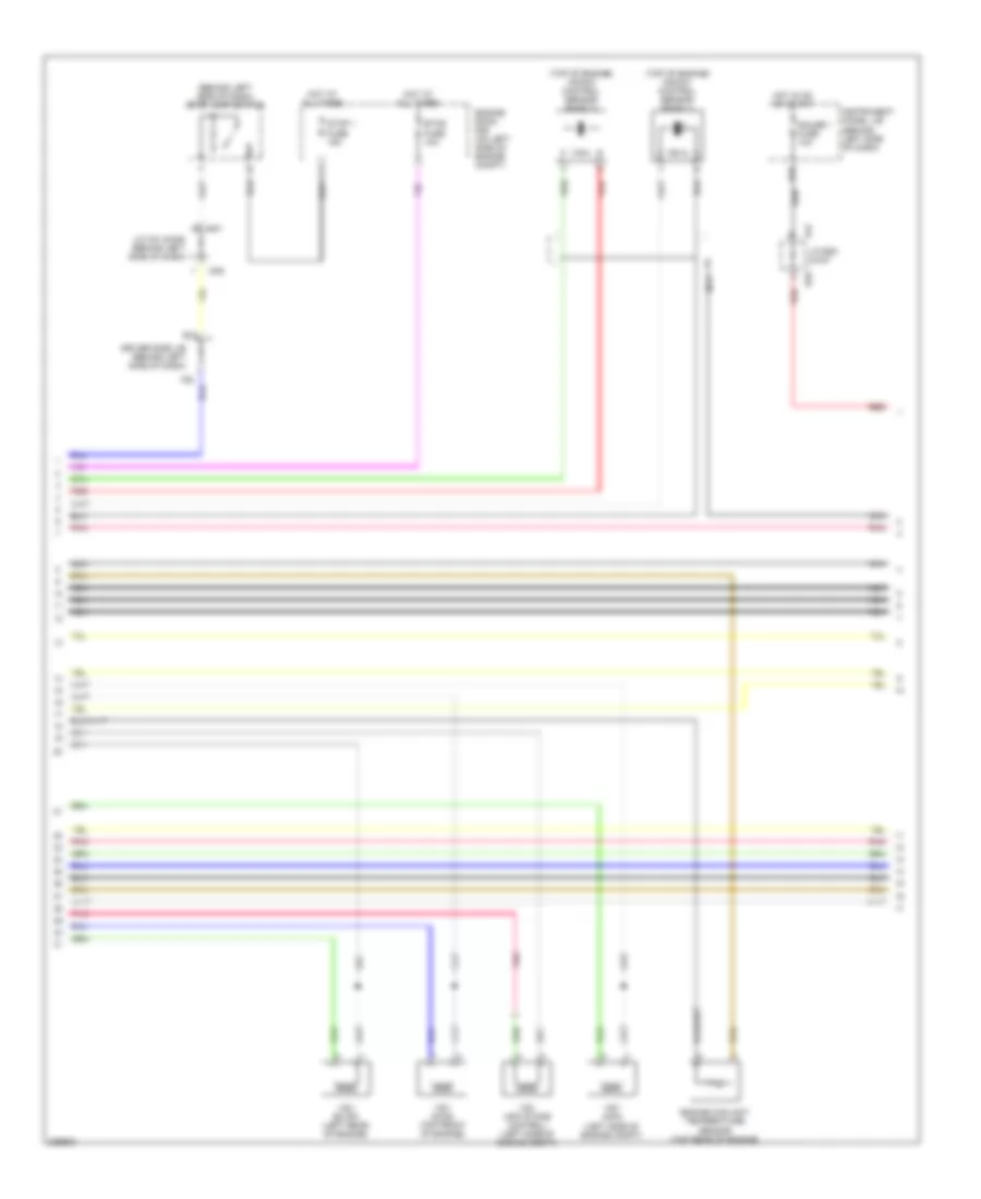
3.5L
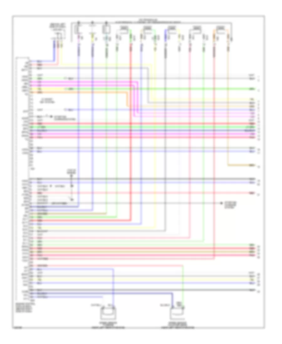
3.5L, Engine Performance Wiring Diagram (1 of 7) for Toyota Avalon XLS 2005
List of elements for 3.5L, Engine Performance Wiring Diagram (1 of 7) for Toyota Avalon XLS 2005:
- (behind left side of dash) j/c a41
- (on transaxle) electronically controlled transmission solenoid
- (top of engine) b2
- +b2
- +bm
- A1a+
- A1a-
- A24
- A2a+
- A2a-
- Accr
- B46
- Batt
- Dsl
- E03
- E04
- E05
- Ekn2
- Eknk
- Engine control module (ecm) (behind right side of dash)
- Epa
- Epa2
- Ha1a
- Ha2a
- Ht2b
- Igsw
- Knk1
- Knk2
- Me01
- Mpmp
- Mrel
- Nc+
- Nc-
- Nt+
- Nt-
- Ox2b
- Pnk
- Ppmp
- Red
- Sl1+
- Sl1-
- Sl2+
- Sl2-
- Sl3+
- Sl3-
- Slt+
- Slt-
- Speed sensor (counter gear) (near left rear of engine)
- Speed sensor (turbine) (near left rear of engine)
- Star
- Starting/ charging system
- Stp
- Tho
- Tho1
- Vcp2
- Vcpa
- Vpa
- Vpa2
- Vpmp
- W/ smart key system
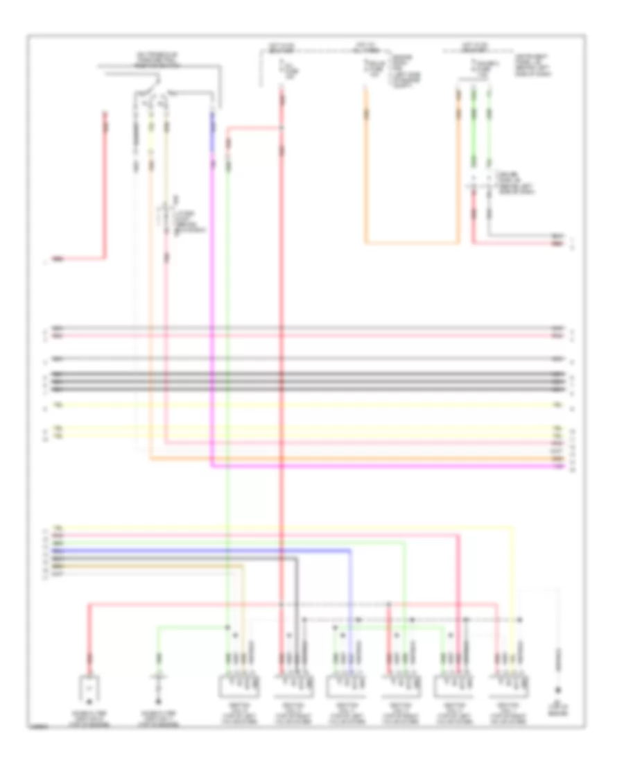
3.5L, Engine Performance Wiring Diagram (2 of 7) for Toyota Avalon XLS 2005
List of elements for 3.5L, Engine Performance Wiring Diagram (2 of 7) for Toyota Avalon XLS 2005:
- (behind left center of dash) accelerator position sensor
- (behind left side of dash) j/c a42
- (under rear of vehicle) leak detection pump assembly
- A1a+
- A1a-
- A2a+
- A2a-
- Air fuel ratio sensor (bank 1 sensor 1) (on right side of engine, in exhaust pipe)
- Air fuel ratio sensor (bank 2 sensor 1) (on left side of engine, in exhaust pipe)
- B1 (on top of engine)
- Canister closed valve
- E2g
- Epa
- Epa2
- Ha1a
- Ha2a
- Heated oxygen sensor (bank 1 sensor 2) (near left side of engine)
- Heated oxygen sensor (bank 2 sensor 2) (on left exhaust manifold)
- Hot in on and start
- Ht1b
- Ht2b
- Ign fuse 10a
- Instrument panel j/b (behind left side of dash)
- Mass air flow meter (on left side of engine compt, part of air intake assembly)
- Mgnd
- Mtrb
- Nca
- Ox1b
- Ox2b
- Pnk
- Pressure sensor
- Red
- Sgnd
- Tha
- Vcc
- Vcp2
- Vcpa
- Vgnd
- Vlvb
- Vout
- Vpa
- Vpa2
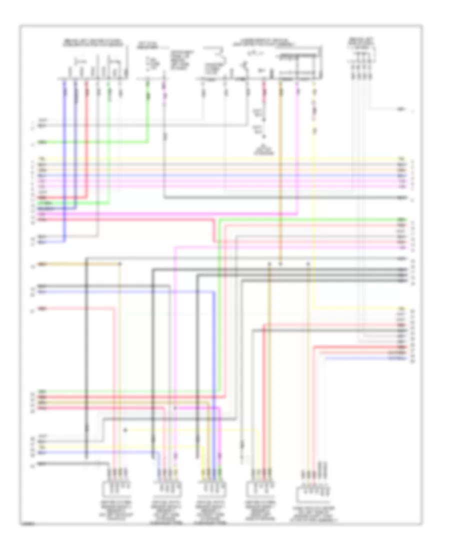
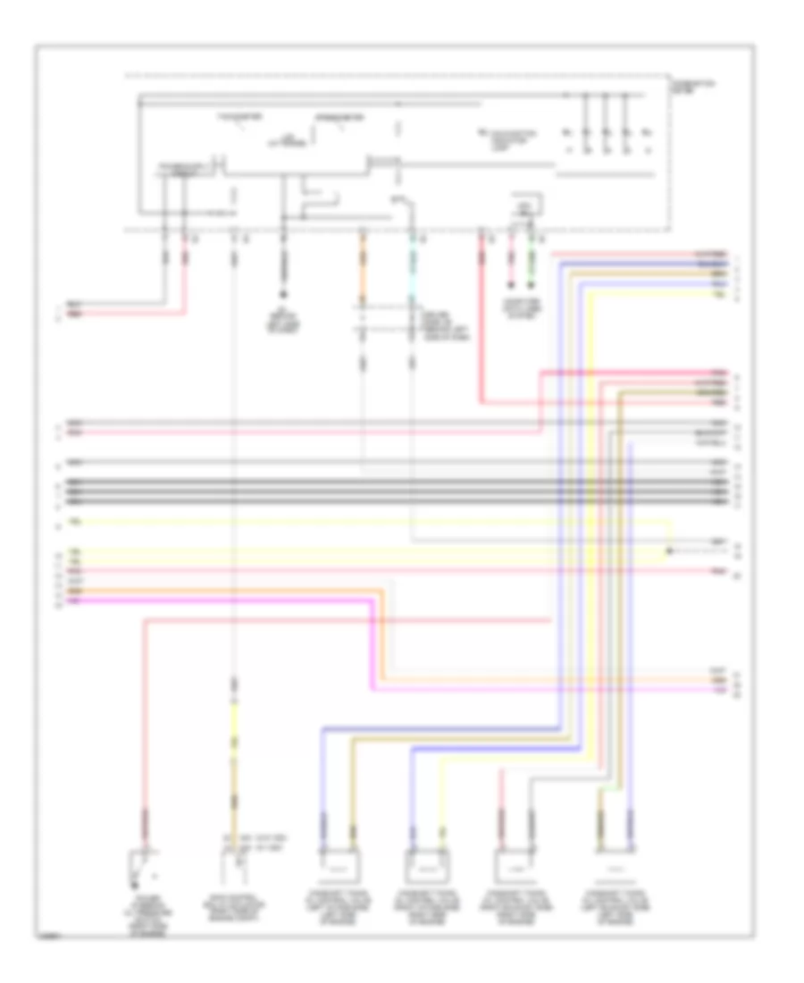
3.5L, Engine Performance Wiring Diagram (3 of 7) for Toyota Avalon XLS 2005
List of elements for 3.5L, Engine Performance Wiring Diagram (3 of 7) for Toyota Avalon XLS 2005:
- (in fuel tank) fuel suction pump & gage assembly
- A/f fuse 25a
- A/f relay
- Acis
- Acm
- Aicv
- B1 (top of engine)
- B2 (top of engine)
- B45
- C/ opn relay
- E01
- E02
- E2g
- Efi 1 fuse 25a
- Efi 2 fuse 10a
- Efi relay
- Engine control module (ecm) (behind right side of dash)
- Engine room r/b (left side of engine compt)
- Ge01
- H10
- Hot at all times
- Ht1b
- Igf1
- Igt1
- Igt2
- Igt3
- Igt4
- Igt5
- Igt6
- Instrument panel j/b (behind left side of dash)
- J/c a51 (left front
- K1 (left "c" pillar)
- Nca
- Of engine compt)
- Ox1b
- Pnk
- Prg
- Red
- Tha
- Throttle body assembly (on top rear of engine)
- Thw
- Vta
- Vta1
- Vta2
3.5L, Engine Performance Wiring Diagram (4 of 7) for Toyota Avalon XLS 2005
List of elements for 3.5L, Engine Performance Wiring Diagram (4 of 7) for Toyota Avalon XLS 2005:
- (behind left side of dash) stop lamp switch
- (left side of engine compt)
- (top of engine) knock control sensor (bank 1)
- (top of engine) knock control sensor (bank 2)
- A41
- B48
- D46
- D47
- Driver side j/b (behind left side of dash)
- E10
- Engine coolant temperature sensor (top rear of engine)
- Engine room r/b (on left side of engine compt)
- Etcs fuse 10a
- Gauge 1 fuse 10a
- Hot at all times
- Hot in on or start
- Instrument panel j/b (behind left side of dash)
- J/c a41 & d46 (behind left side of dash)
- J/c b48 & d47
- Nca
- Pnk
- Red
- Stop 1 fuse 15a
- Vsv (acis) (top front of engine)
- Vsv (acm)
- Vsv (air intake control) (left side of engine compt)
- Vsv (evap) (left rear of engine)
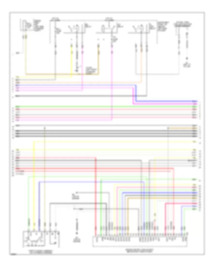
3.5L, Engine Performance Wiring Diagram (5 of 7) for Toyota Avalon XLS 2005
List of elements for 3.5L, Engine Performance Wiring Diagram (5 of 7) for Toyota Avalon XLS 2005:
- (on transaxle) park/neutral position switch
- B1 (top of engine)
- B48
- D10
- Driver side j/b (behind left side of dash)
- Ecu-b fuse 10a
- Engine room r/b (left side of engine compt)
- G12
- Gauge 2 fuse 7.5a
- Gnd
- Hot at all times
- Hot in on or start
- I11
- Igf
- Ignition coil 1 (top of right valve cover)
- Ignition coil 2 (top of left valve cover)
- Ignition coil 3 (top of right valve cover)
- Ignition coil 4 (top of left valve cover)
- Ignition coil 5 (top of right valve cover)
- Ignition coil 6 (top of left valve cover)
- Igt1
- Igt2
- Igt3
- Igt4
- Igt5
- Igt6
- Inj fuse 15a
- Instrument panel j/b (behind left side of dash)
- J/c b48 & d47 (behind d47 glove box)
- K15
- Nca
- Noise filter (ignition 1) (top of engine)
- Noise filter (ignition 2) (top of engine)
- Pnk
- Red
3.5L, Engine Performance Wiring Diagram (6 of 7) for Toyota Avalon XLS 2005
List of elements for 3.5L, Engine Performance Wiring Diagram (6 of 7) for Toyota Avalon XLS 2005:
- A34 (w/ vsc)
- A40 (w/o vsc)
- Camshaft timing oil control valve (left exhaust side) (left side of engine)
- Camshaft timing oil control valve (left intake side) (left side of engine)
- Camshaft timing oil control valve (right exhaust side) (right side of engine)
- Camshaft timing oil control valve (right intake side) (right side of engine)
- Combination meter
- Computer data lines system
- Driver side j/b (behind left side of dash)
- E1 (behind
- Lcd (a/t range)
- Left side of dash)
- Malfunction indicator lamp
- Mpx b+
- Nca
- Pnk
- Power steering oil pressure switch (right side of engine)
- Red
- Skid control ecu w/ actuator (right side of engine compt)
- Sp1
- Speedometer
- Tachometer
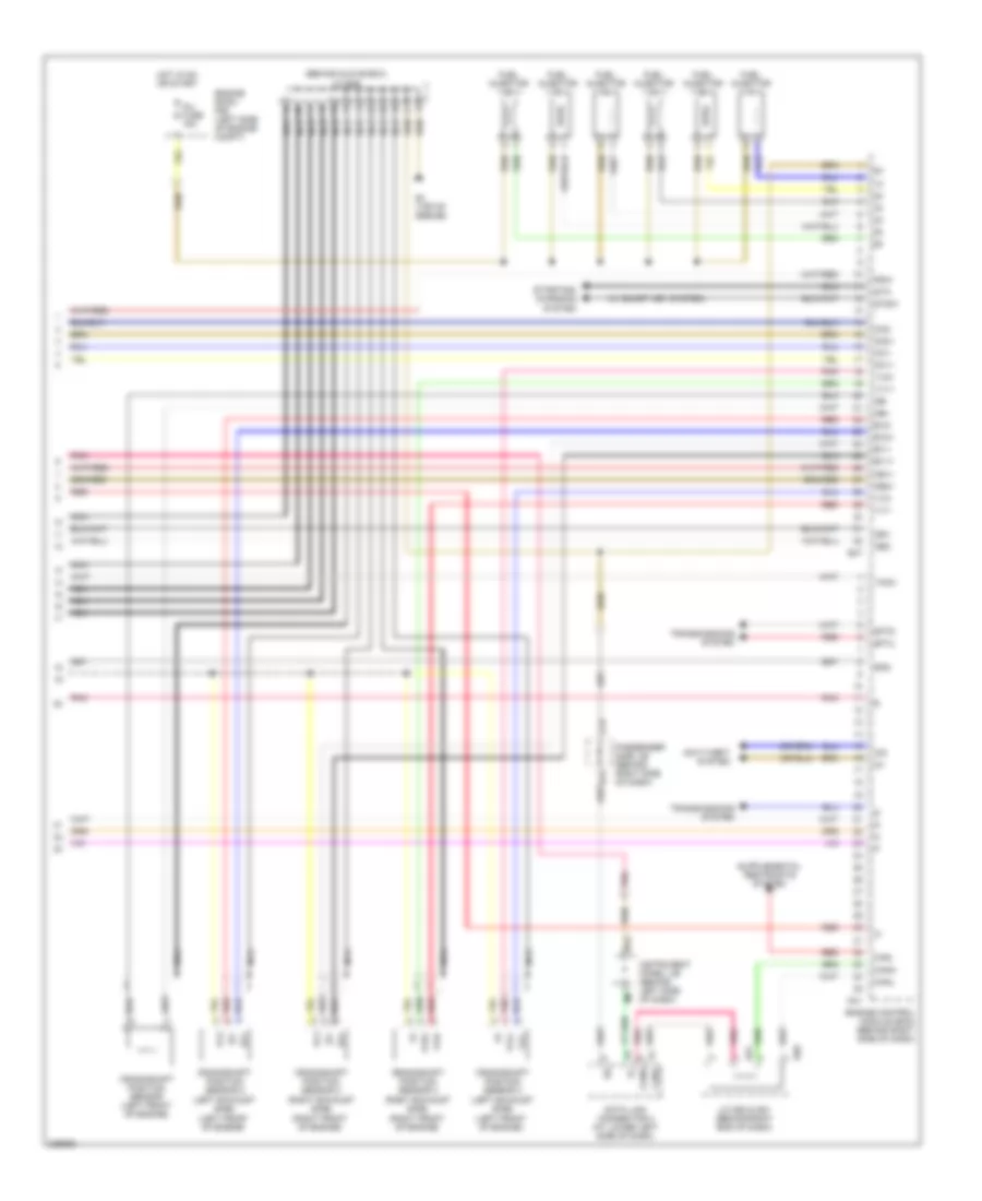
3.5L, Engine Performance Wiring Diagram (7 of 7) for Toyota Avalon XLS 2005
List of elements for 3.5L, Engine Performance Wiring Diagram (7 of 7) for Toyota Avalon XLS 2005:
- (behind glove box) j/c b49
- (left front of engine)
- (right front of engine)
- (w/ smart key system)
- Anti-theft system
- B1 (top of engine)
- B47
- C17
- Canh
- Canl
- Crankshaft position sensor (left front of engine)
- Crankshaft position sensor 2 (left exhaust side)
- Crankshaft position sensor 2 (right exhaust side)
- Crankshaft position sensor 3 (left exhaust side)
- Crankshaft position sensor 3 (right exhaust side)
- D17
- D41
- D50
- D51
- Data link connector 3 (at lower left side of dash)
- Engine control module (ecm) (behind right side of dash)
- Engine room r/b (left side of engine compt)
- Ev1+
- Ev1-
- Ev2+
- Ev2-
- Ex+
- Ex-
- F/ps
- Fuel injector
- H12
- Hot in on or start
- Imi
- Imo
- Inj fuse 15a
- Instrument panel j/b (behind left side of dash)
- J/c d50 & d51 (behind right end of dash)
- Nca
- Ne+
- Ne-
- Oc1+
- Oc1-
- Oc2+
- Oc2-
- Oe1+
- Oe1-
- Oe2+
- Oe2-
- Passenger side j/b (behind right side of dash)
- Pnk
- Psw
- Red
- Sftd
- Sftu
- Spd
- Sta
- Starting/ charging system
- Stsw
- Tach
- Transmissions system
- Vc2
- Vv1+
- Vv1-
- Vv2+
- Vv2-
- Vvl+
- Vvl-
- Vvr+
- Vvr-
EXTERIOR LIGHTS
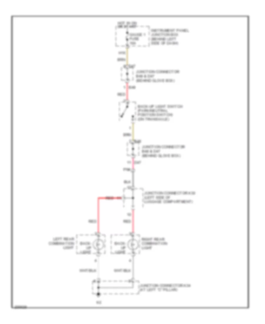
Back-up Lamps Wiring Diagram for Toyota Avalon XLS 2005
List of elements for Back-up Lamps Wiring Diagram for Toyota Avalon XLS 2005:
- B48
- Back- up light
- Back-up light switch (park/neutral position switch) (on transaxle)
- D47
- Gauge 1 fuse 10a
- H16
- Hot in on or start
- Instrument panel junction box (behind left side of dash)
- Junction connector b48 & d47 (behind glove box)
- Junction connector k30 (left side of luggage compartment)
- Junction connector k34 (at left "c" pillar)
- Left rear combination light
- Pnk
- Red
- Right rear combination light
Exterior Lamps Wiring Diagram (1 of 2) for Toyota Avalon XLS 2005
List of elements for Exterior Lamps Wiring Diagram (1 of 2) for Toyota Avalon XLS 2005:
- (behind left side of dash) driver side j/b
- (behind left side of dash) e1
- (behind right side of dash) passenger side j/b
- (left side of luggage compt) junction connector k30 & k31
- B18
- Body ecu
- Body ecu (attached to driver side j/b)
- Combination meter
- Computer data lines system
- D1 (left kick panel)
- D10
- D13
- D14
- Dome fuse 7.5a
- Driver side j/b (behind left side of dash)
- E11
- Ecu ig 1 fuse 7.5a
- Ecu-b fuse 10a
- Engine room r/b (on left side of engine compartment)
- F10
- F11
- F13
- F14
- F19
- G10
- G20
- Gauge 1 fuse 10a
- H10
- Haz
- Hazard warning signal switch
- Headlamp dimmer switch assembly
- Hot at all times
- Hot in on or start
- I10
- Instrument panel j/b (behind left side of dash)
- Junction connector a51 (left front of engine compt)
- Junction connector a53 (right front of engine compt)
- Junction connector d53 (behind center of dash)
- Junction connector k34 (at left "c" pillar)
- K19
- K20
- K23
- K25
- K29
- K30
- K31
- L10
- Left
- Left front side marker lamp
- Left rear combination lamp
- Left rear outer view mirror (w/ memory)
- Left turn ind
- License plate lamp
- Mpx1
- Mpx2
- P12
- Pnk
- Red
- Right
- Right front side marker lamp
- Right rear combination lamp
- Right rear outer view mirror (w/ memory)
- Right turn ind
- Stop
- Tail
- Tail fuse 10a
- Tail ind (except usa)
- Tail relay
- Trly
- Trnl
- Trnr
- Turn
- Turn signal flasher (behind left side of dash)
- Turn/ haz fuse 15a
- Windshield wiper switch assembly
Exterior Lamps Wiring Diagram (2 of 2) for Toyota Avalon XLS 2005
List of elements for Exterior Lamps Wiring Diagram (2 of 2) for Toyota Avalon XLS 2005:
- (w/ dynamic radar cruise control)
- A34
- A40
- A41
- Brk relay
- C13
- Center stop lamp
- D46
- Ecu ig 2 fuse 10a
- Engine room r/b (on left side of engine compartment)
- F15
- F19
- Hot at all times
- Hot in on or start
- Instrument panel j/b (behind left side of dash)
- Junction connector a41 & d46 (behind left side of dash)
- Junction connector a41 (behind left side of dash)
- Junction connector a42 (behind left side of dash)
- Junction connector a51 (left front of engine compt)
- Junction connector a53 (right front of engine compt)
- Junction connector k34 (at left "c" pillar)
- Left front turn signal & parking parking lamp
- Noise filter (dome & stop) (left "c" pillar)
- Pnk
- Radar cc fuse 7.5a (w/ dynamic radar cruise control)
- Right front turn signal & parking parking lamp
- Skid control ecu w/ actuator (at right side of engine compt)
- Stop 1 fuse 15a
- Stop fuse 7.5a
- Stop lamp switch (behind left side of dash)
- Stp0
- Stp1
- Stp2
- Turn
- W/ vsc
- W/o dynamic radar cruise control
- W/o vsc
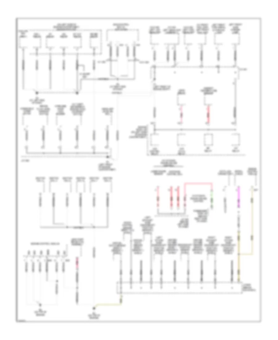
GROUND DISTRIBUTION
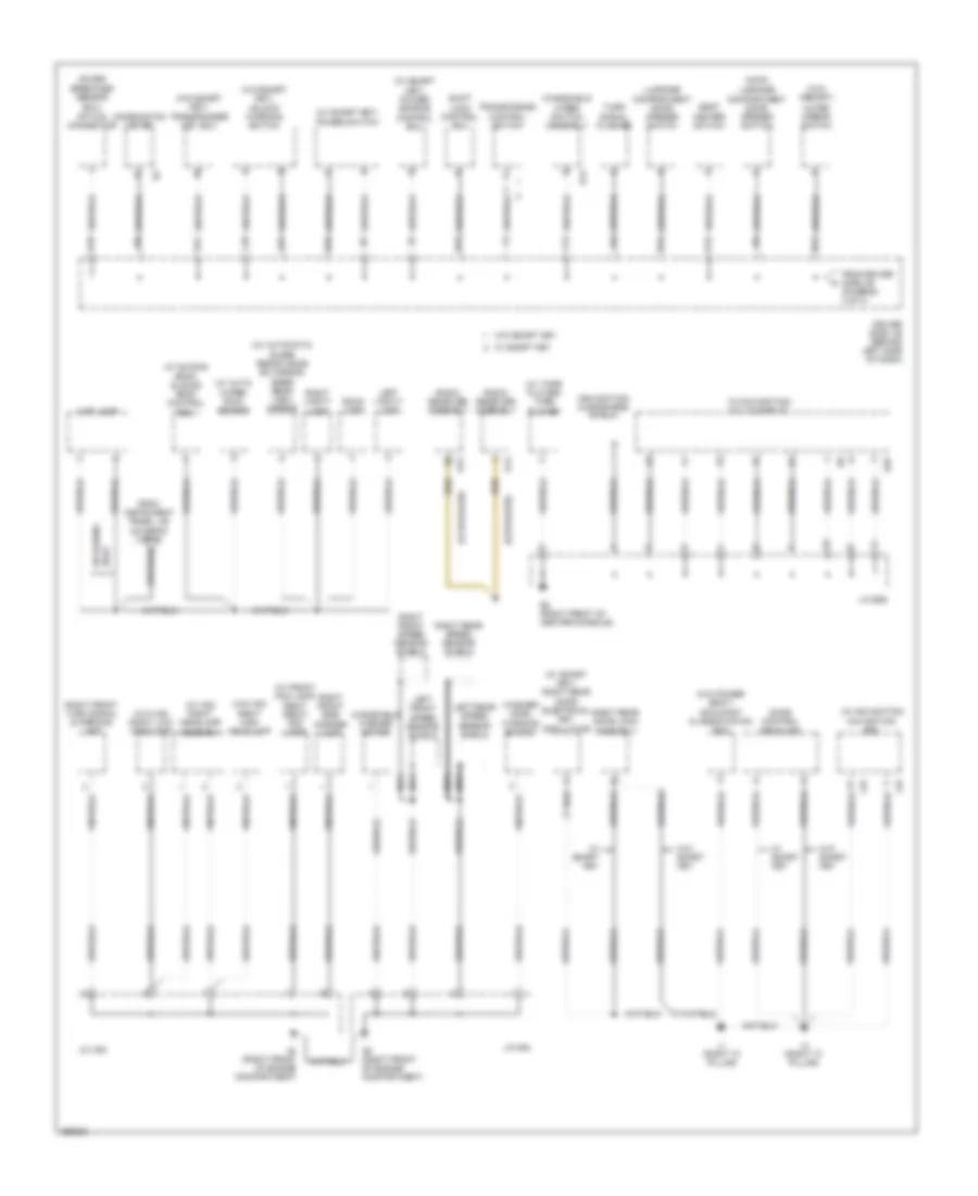
Ground Distribution Wiring Diagram (1 of 4) for Toyota Avalon XLS 2005
List of elements for Ground Distribution Wiring Diagram (1 of 4) for Toyota Avalon XLS 2005:
- (left
- (left front of engine compartment)
- (on left side of engine compartment) engine room r/b
- (right
- (w/ dynamic radar cruise control)
- (w/ front fog lamp) left front fog lamp
- (w/ hid) left headlamp assembly
- (w/ theft deterrent) engine hood courtesy switch
- (w/o hid) left high headlamp
- (w/o hid) left low headlamp
- A/f relay
- A1 (left front of engine compt)
- A3 (at left end of dash)
- A34
- A40
- A6 (at right end of dash)
- Air fuel ratio sensor (bank 1 sensor 1) shield
- Air fuel ratio sensor (bank 2 sensor 1) shield
- Ambient temperature sensor
- B1 (on top of engine)
- B2 (on top of engine)
- B45
- B46
- B47
- Brake fluid level warning switch
- C17
- Cooling fan ecu
- Crankshaft position sensor shield
- D17
- Data link connector 3
- Distance control ecu
- E01
- E02
- E03
- E04
- E05
- Efi relay
- Engine control module
- Engine room j/b (on left side of engine compartment)
- Exhaust side) crankshaft position sensor 2 shield
- Fan 1 relay
- Head relay
- Headlamp leveling ecu
- Heated oxygen sensor (bank 1 sensor 2) shield
- Heated oxygen sensor (bank 2 sensor 2) shield
- Ig2 relay
- Ignition coil 1
- Ignition coil 2
- Ignition coil 3
- Ignition coil 4
- Ignition coil 5
- Ignition coil 6
- Intake side) crankshaft position sensor 2 shield
- Intake side) crankshaft position sensor 3 shield
- J/c a42 (behind left side of dash)
- J/c a51
- J/c a52
- J/c b49 (behind glove box)
- Knock control sensor (bank 1 & 2) shield
- Laser radar sensor
- Leak pump detection assembly
- Left front side marker lamp
- Left front turn signal & parking lamp
- Me01
- Nca
- Passenger side j/b (behind right side of dash)
- Pnk
- Red
- Rr def relay
- Skid control ecu w/ actuator
- Spiral cable
- St cut relay
- St relay
- W/ dynamic radar cruise control
- W/ smart key
- W/ vsc
- W/o vsc
- Windshield wiper motor
- Wip (hi/lo) relay
- Wip control relay
- Wireless door lock buzzer
Ground Distribution Wiring Diagram (2 of 4) for Toyota Avalon XLS 2005
List of elements for Ground Distribution Wiring Diagram (2 of 4) for Toyota Avalon XLS 2005:
- (12 speaker)
- (9 speaker)
- (glass breakage sensor
- (main) luggage compartment door opener switch
- (navigation) microphone shield
- (w/ auto wiper) rain sensor
- (w/ automatic glare resistance ec mirror) inner rear view mirror
- (w/ front fog lamp) right front fog lamp
- (w/ hid) right headlamp assembly
- (w/ navigation) multi-display
- (w/ navigation) navigation ecu
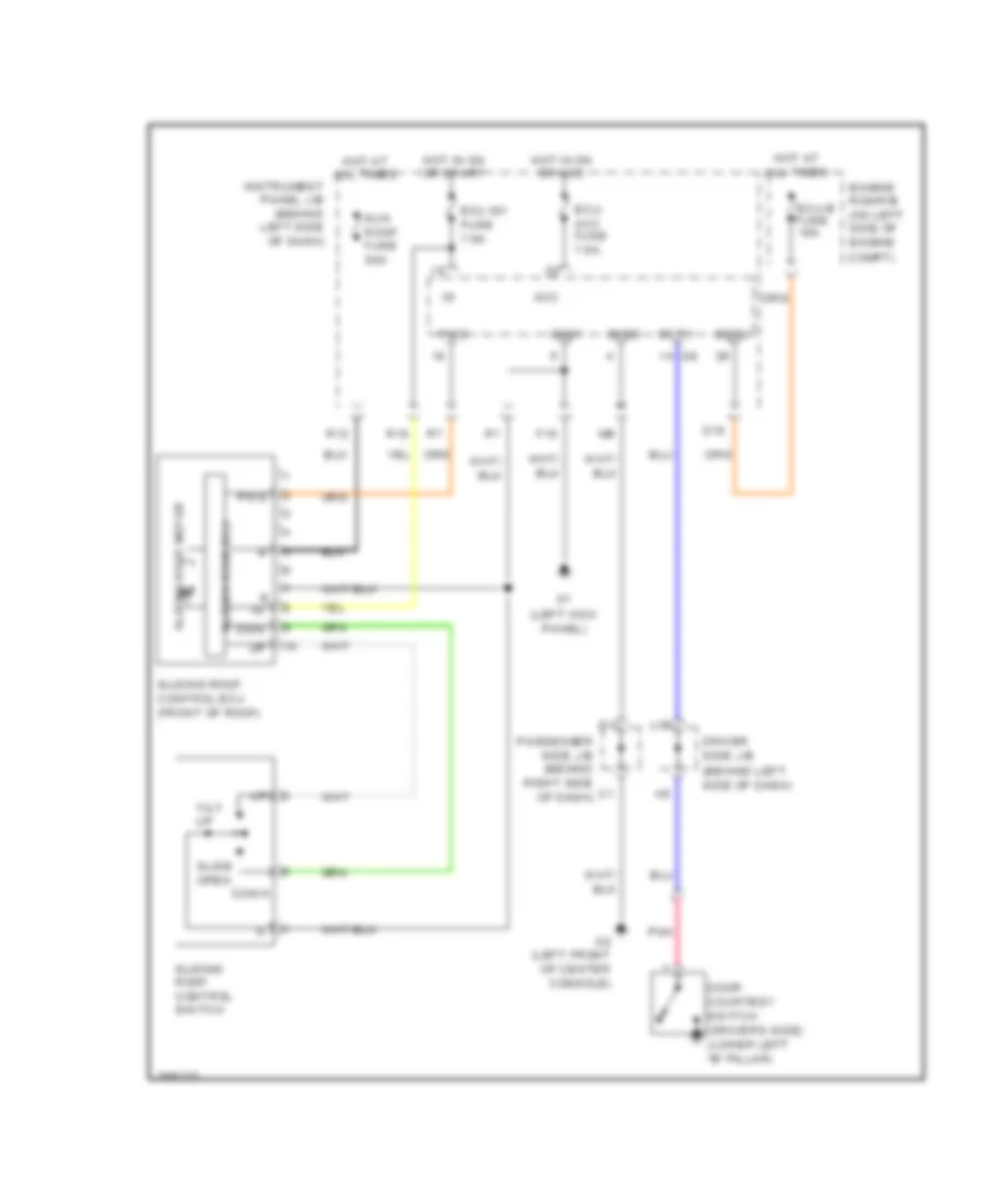
- (w/ sliding roof) sliding roof control ecu
- (w/ smart key) power source control ecu
- (w/ smart key) power switch
- (w/ smart key) right rear door electrical key oscillator
- (w/ tape player) tape player
- (w/o hid) right high headlamp
- (w/o hid) right low headlamp
- (w/o memory)
- (w/o power seat) occupant classification ecu
- (w/o smart key) transponder key ecu
- (w/o smart key) unlock warning switch
- A4 (right front of engine compartment)
- A5 (right front of engine compartment)
- Combination meter
- D13
- D15
- Door control receiver
- Driver side j/b (behind left side of dash)
- E12
- E13
- E2 (right front of center console)
- E25
- Ecu)
- F13
- From driver side j/b (diagram 3 of 4)
- From instrument panel j/b (diagram 3 of 4)
- G11
- G13
- H11
- I10
- J/c a53
- J/c a54
- J/c e29
- K10
- K21
- L1 (right "c" pillar)
- L10
- L16
- L18
- L2 (right "c" pillar)
- L21
- Left front speed sensor shield
- Left rear speed sensor shield
- Left vanity lamp
- Luggage compartment door opener switch
- Map lamp
- Nca
- Option connector
- Outer mirror switch
- Radio receiver assembly
- Right front side marker lamp
- Right front speed sensor shield
- Right front turn signal & parking lamp
- Right rear door lock assembly
- Right rear speed sensor shield
- Right vanity lamp
- Room lamp
- Seat heater switch
- Shift lock control ecu
- Transmission control switch
- Turn signal flasher
- W/ sliding roof
- W/ smart key
- W/o smart key
- Washer level warning switch
- Windshield washer motor
- Windshield wiper switch assembly
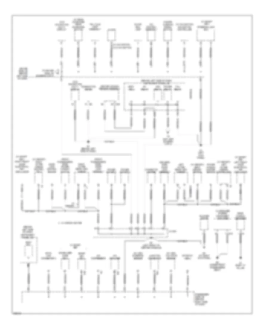
Ground Distribution Wiring Diagram (3 of 4) for Toyota Avalon XLS 2005
List of elements for Ground Distribution Wiring Diagram (3 of 4) for Toyota Avalon XLS 2005:
- (12 speaker) stereo component amplifier
- (behind left side of dash)
- (behind left side of dash) instrument panel j/b
- (driver's side) door lock assembly
- (front passenger's side) door lock assembly
- (front passenger's side) power window switch
- (w/ memory) left outer mirror control ecu
- (w/ memory) right outer mirror control ecu
- (w/ memory) seat memory switch
- (w/ navigation)
- (w/ navigation) navigation controller
- (w/ rear sunshade) rear sunshade switch
- (w/ smart key)
- (w/ smart key) left front door electrical key oscillator
- (w/ smart key) right front door electrical key oscillator
- (w/ vsc) steering sensor
- (w/ vsc) yaw rate sensor
- (w/o navigation) multi- display
- A/c amplifier
- A/c compressor
- A/c control assembly
- Acc relay
- B11
- B15
- Blower motor
- Body ecu
- C11
- C12
- C15
- Center air bag sensor assembly
- Cigarette lighter
- Clock
- Combination meter
- D1 (left kick panel)
- D11
- D12
- D2 (left front of center console)
- D23
- D3 (at right kick panel)
- D37
- D39
- D52
- Data link connector 3
- Door lock control switch
- Driver side j/b (behind left side of dash)
- E1 (behind left side of dash)
- E3 (under front
- F10
- Gateway ecu
- Glove box lamp
- H10
- H13
- Hazard warning signal switch
- I21
- Ig1 relay
- Immobilizer code ecu
- Instrument panel j/b
- J/c d53
- J10
- J21
- Junction connector
- L20
- Left outer rear view mirror
- Passenger side j/b (behind right side of dash)
- Passenger's seat)
- Power outlet 1
- Power outlet 2
- Power relay
- Power window master switch
- Q1 (right "c" pillar)
- Rear window defogger
- Right outer rear view mirror
- Smart key ecu
- Steering lock ecu
- Tail relay
- Telltale lamp assembly
- To driver side j/b (diagram 2 of 4)
- To map lamp (diagram 2 of 4)
- W/ memory
- W/ mirror heater
- W/ smart key
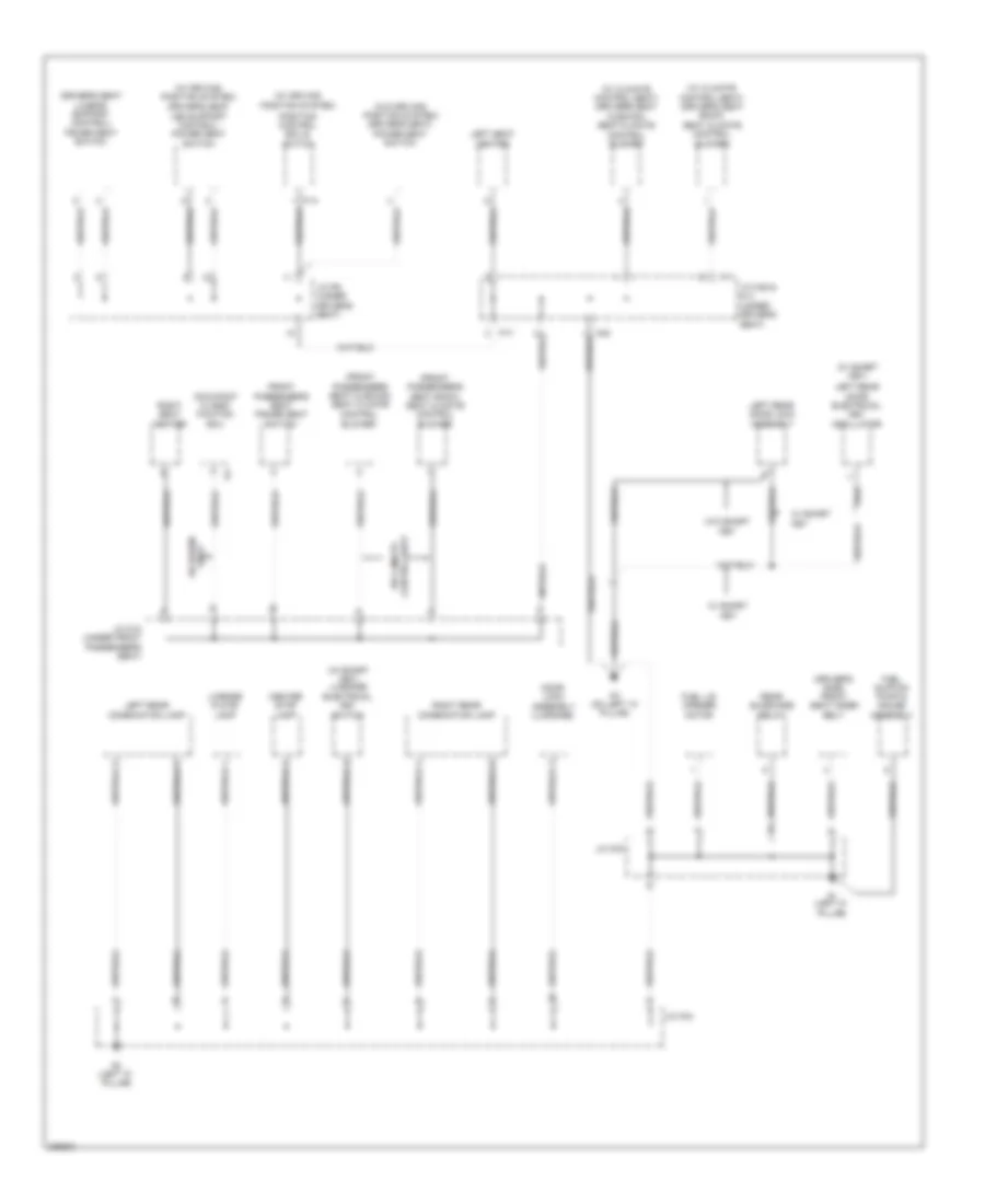
Ground Distribution Wiring Diagram (4 of 4) for Toyota Avalon XLS 2005
List of elements for Ground Distribution Wiring Diagram (4 of 4) for Toyota Avalon XLS 2005:
- (driver's seat lumbar support control) power seat switch
- (driver's side) front seat inner belt
- (front passenger's seat back) seat climate control blower
- (front passenger's seat cushion) seat climate
- (w/ climate control seat) (driver's seat back) seat climate control blower
- (w/ climate control seat) (driver's seat cushion) seat climate control blower
- (w/ driving position system)
- (w/ driving position system) (driver's seat
- (w/ smart key)
- (w/ smart key) luggage electrical key switch
- (w/o driving position system) (driver's seat) power seat switch
- Center stop lamp
- Control blower
- Control seat
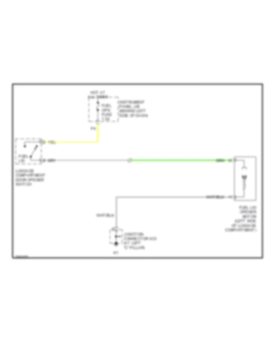
- Door lock assembly (luggage)
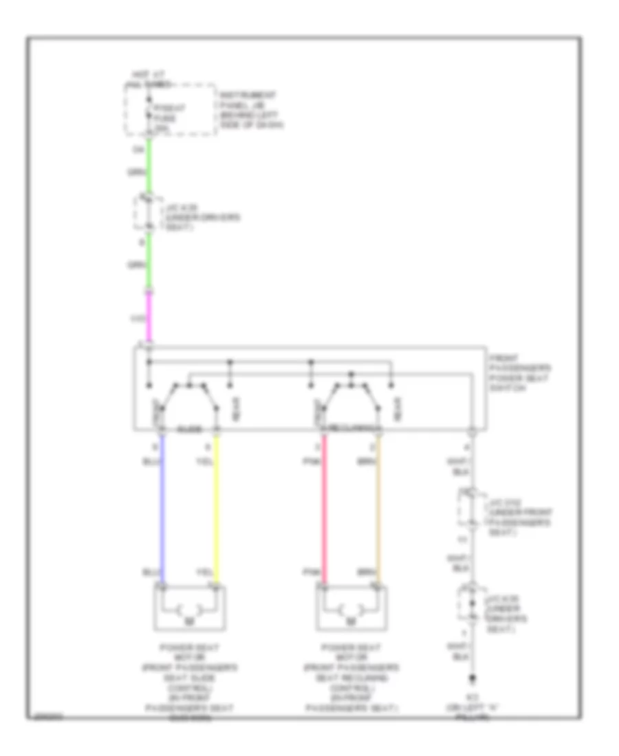
- Front passenger's seat power seat switch
- Fuel lid opener motor
- Fuel suction pump & gauge assembly
- J/c k33
- J/c k34
- J/c k35 & p17 (under driver's seat)
- J/c o12 (under front passenger's seat)
- J/c p9 (under driver's seat)
- K1 (left "c" pillar)
- K2 (left "c" pillar)
- K3 (on left "a" pillar)
- Left rear combination lamp
- Left rear door electrical key oscillator
- Left rear door lock assembly
- Left seat heater
- Leg support control) power seat switch
- License plate lamp
- Occupant classi- fication ecu
- P14
- P17
- Position control ecu & switch
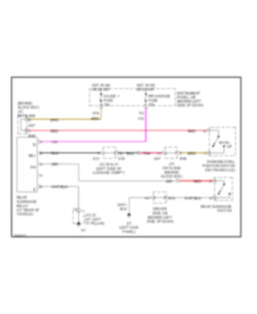
- Rear sunshade relay
- Right rear combination lamp
- Right seat heater
- W/ climate
- W/ power seat
- W/ smart key
- W/o smart key
HEADLIGHTS
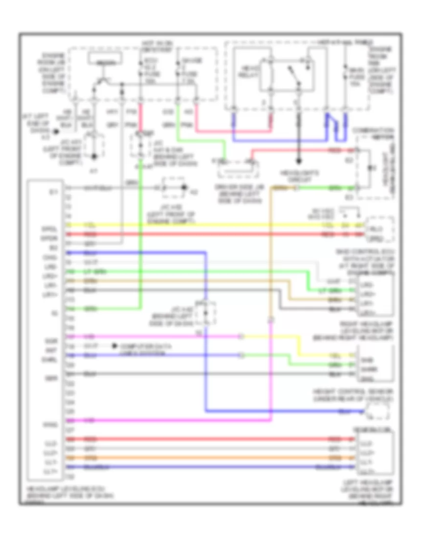
Headlamp Beam Adjustment Wiring Diagram for Toyota Avalon XLS 2005
List of elements for Headlamp Beam Adjustment Wiring Diagram for Toyota Avalon XLS 2005:
- (at left end of dash) a3
- A41
- Beam level ind headlight
- Chg-
- Combination meter
- Computer data lines system
- D46
- Driver side j/b (behind left side of dash)
- Ecu ig 2 fuse 10a
- Engine room j/b (on left side of engine compt)
- Engine room r/b (on left side of engine compt)
- F19
- G12
- Gauge fuse 7.5a
- Generator
- H11
- Head relay
- Headlamp leveling ecu (behind left side of dash)
- Headlights circuit
- Height control sensor (under rear of vehicle)
- Hot at all times
- Hot in on or start
- Init
- J/c a41 & d46 (behind left side of dash)
- J/c a42 (behind left side of dash)
- J/c a51 (left front of engine compt)
- J/c a52 (left front of engine compt)
- K15
- Left headlamp leveling motor (behind right headlamp)
- Ll1+
- Ll1-
- Ll2+
- Ll2-
- Lr1+
- Lr1-
- Lr2+
- Lr2-
- Main fuse 15a
- Micon
- Pnk
- Red
- Right headlamp leveling motor (behind right headlamp)
- Rlo
- Rro
- Sbr
- Sgr
- Shb
- Shg
- Shrl
- Shrr
- Skid control ecu with actuator (at right side of engine compt)
- Spdl
- Spdr
- W/ vsc w/o vsc
- Wng
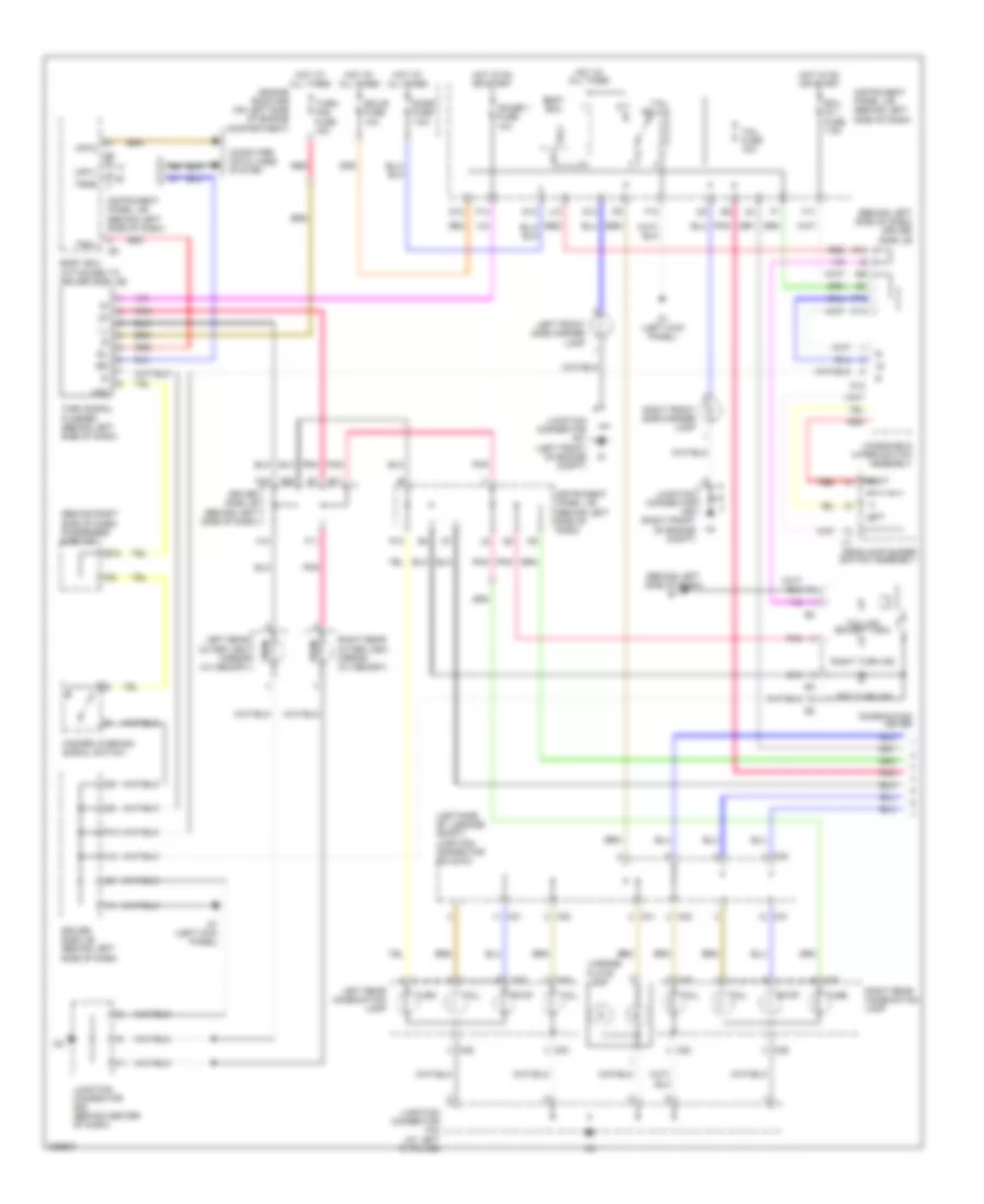
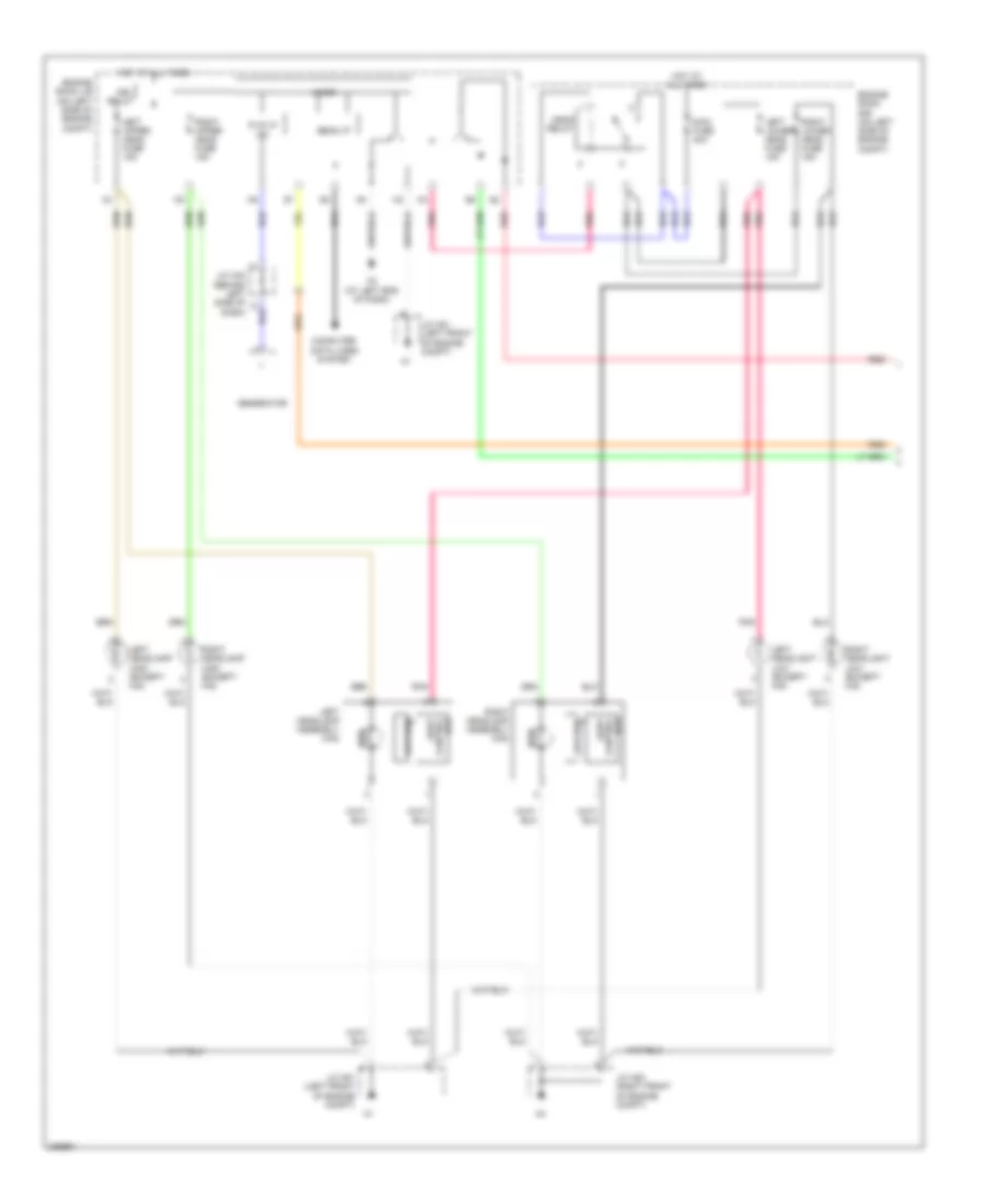
Headlamps & Fog Lamps Wiring Diagram (1 of 2) for Toyota Avalon XLS 2005
List of elements for Headlamps & Fog Lamps Wiring Diagram (1 of 2) for Toyota Avalon XLS 2005:
- A3 (at left end of dash)
- Bean i/f
- Computer data lines system
- Drl relay
- Ecu control light
- Engine room j/b (on left side of engine compt)
- Engine room r/b (on left side of engine compt)
- Generator
- Head relay
- High
- Hot at all times
- J/c a42 (behind left side of dash)
- J/c a51 (left front of engine compt)
- J/c a53 (right front of engine compt)
- Left headlamp assembly (hid)
- Left headlamp high (except hid)
- Left headlight low (except hid)
- Left lower head fuse 15a
- Left upper head fuse 15a
- Light control ecu
- Low (hid)
- Main fuse 40a
- Micon
- P-i/p i/f (ig)
- Pnk
- Red
- Right headlamp assembly (hid)
- Right headlamp high (except hid)
- Right headlight low (except hid)
- Right lower head fuse 15a
- Right upper head fuse 15a
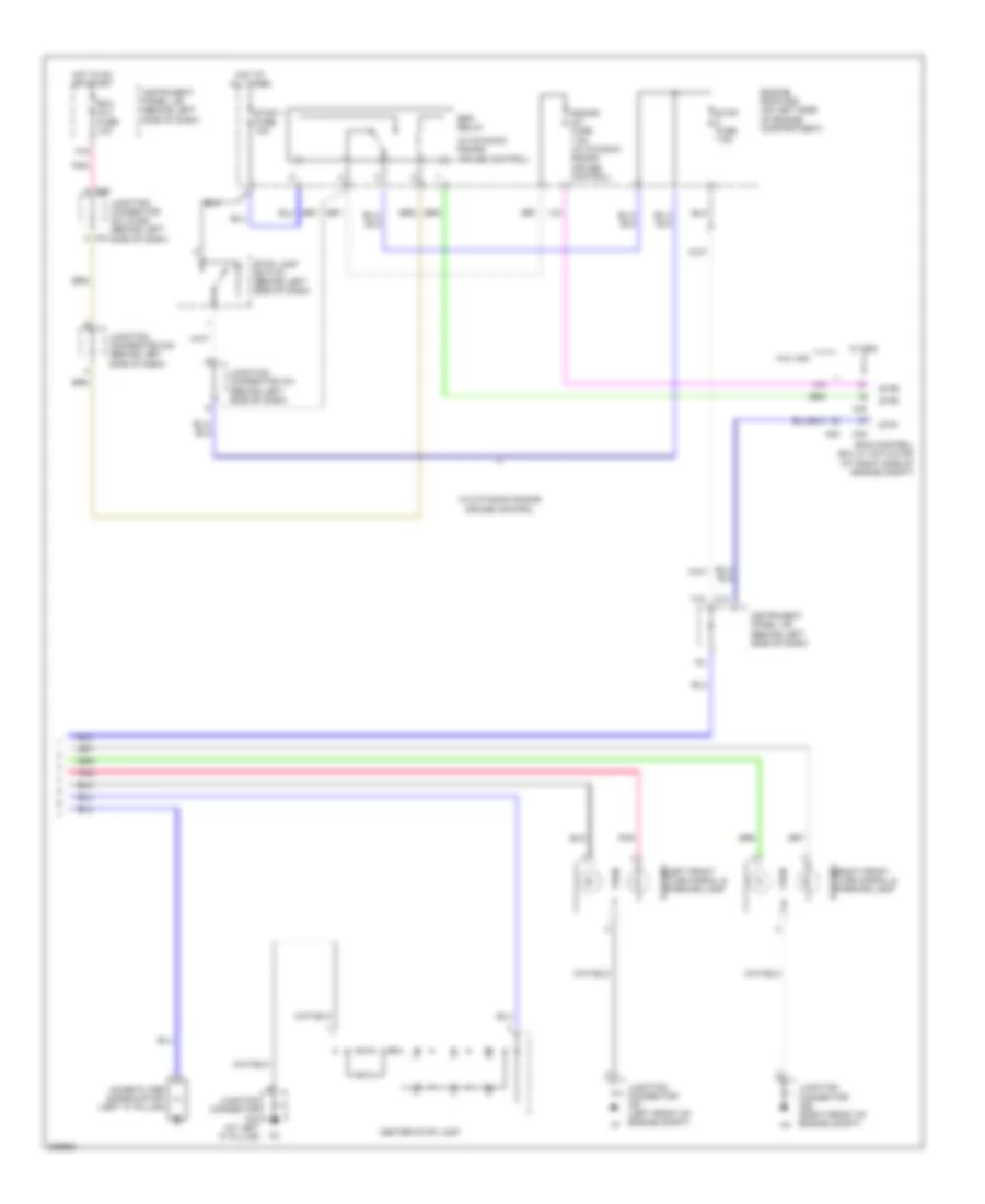
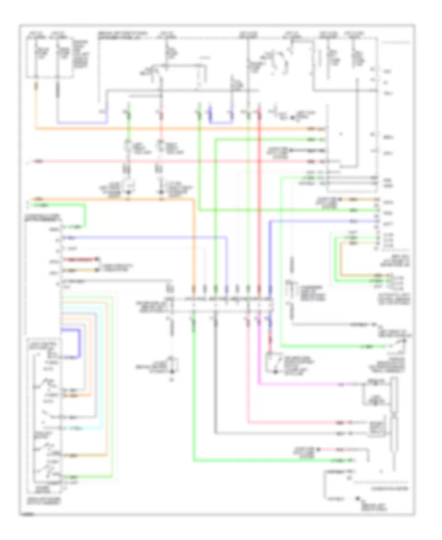
Headlamps & Fog Lamps Wiring Diagram (2 of 2) for Toyota Avalon XLS 2005
List of elements for Headlamps & Fog Lamps Wiring Diagram (2 of 2) for Toyota Avalon XLS 2005:
- (behind left side of dash) instrument panel j/b
- (left kick panel) d1
- (usa) head ind
- Acc
- Auto
- Automatic light control sensor (on top of dash)
- Beam ind
- Becu
- Body ecu (attached to driver side j/b)
- C1 red
- C14
- Cltb
- Clte
- Clts
- Combination meter
- Computer data lines system
- D10
- D13
- D2 (left front of center console)
- Dcty
- Dimmer switch
- Dome fuse 7.5a
- Driver side j/b (behind left side of dash)
- Driver's side door courtesy switch (lower left "b" pillar)
- E1 (behind left side of dash)
- Ecu acc fuse 7.5a
- Ecu ig 1 fuse 7.5a
- Ecu-b fuse 10a
- Engine room r/b (on left side of engine compt)
- F10
- F11
- F13
- F14
- F19
- Ffgo
- Flash
- Fog fuse 15a
- Fog relay
- Foglight
- Gauge 2 fuse 7.5a
- Gnd2
- Head
- Headlamp dimmer switch assembly
- High
- Hot at all times
- Hot in acc or on
- Hot in on or start
- I4 red
- J/c a51 (left front of engine compt)
- J/c a53 (right front of engine compt)
- J/c d53 (behind center of dash)
- K14
- K15
- K19
- L10 red
- L16
- Left front fog lamp
- Light control switch
- Mpx1
- Mpx2
- Off
- Parking brake switch (on parking brake pedal assembly)
- Passenger side j/b (behind right side of dash)
- Pkb
- Pnk
- Red
- Right front fog lamp
- Switch
- Tail
- Tail fuse 10a
- Tail relay
- Trly
- Windshield wiper switch assembly
HORN
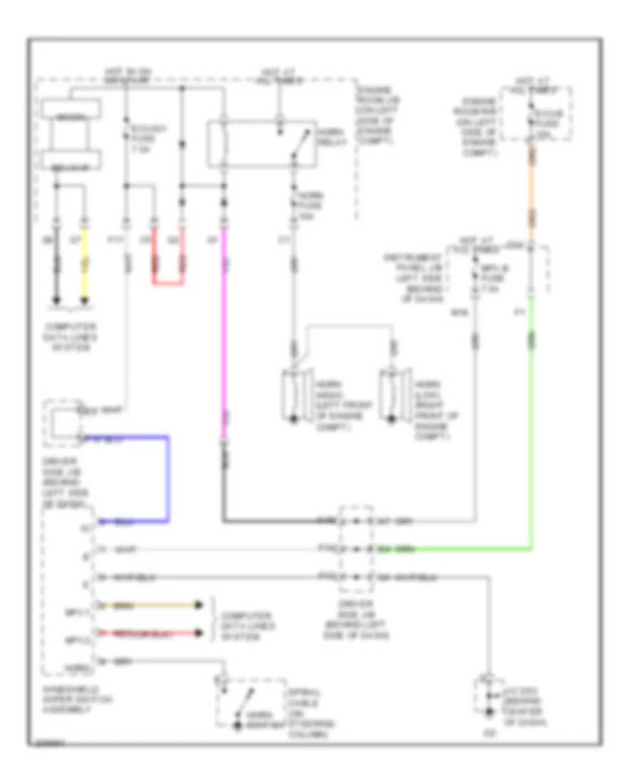
Horn Wiring Diagram for Toyota Avalon XLS 2005
List of elements for Horn Wiring Diagram for Toyota Avalon XLS 2005:
- Bean i/f
- Compt)
- Computer data lines system
- D10
- Driver side j/b (behind left side of dash)
- Ecu-b fuse 10a
- Ecu-ig1 fuse 7.5a
- Engine room j/b (on left side of engine compt)
- Engine room r/b (on left side of engine compt)
- F11
- F13
- F14
- F19
- Horn
- Horn (high) (left front of engine
- Horn (low) (right front of engine compt)
- Horn fuse 10a
- Horn relay
- Horn switch
- Hot at all times
- Hot in on or start
- Instrument panel j/b left side (behind of dash)
- J/c d53 (behind center of dash)
- K18
- M18
- Micon
- Mpx-b fuse 7.5a
- Mpx1
- Mpx2
- Red
- Spiral cable (on steering column)
- Windshield wiper switch assembly
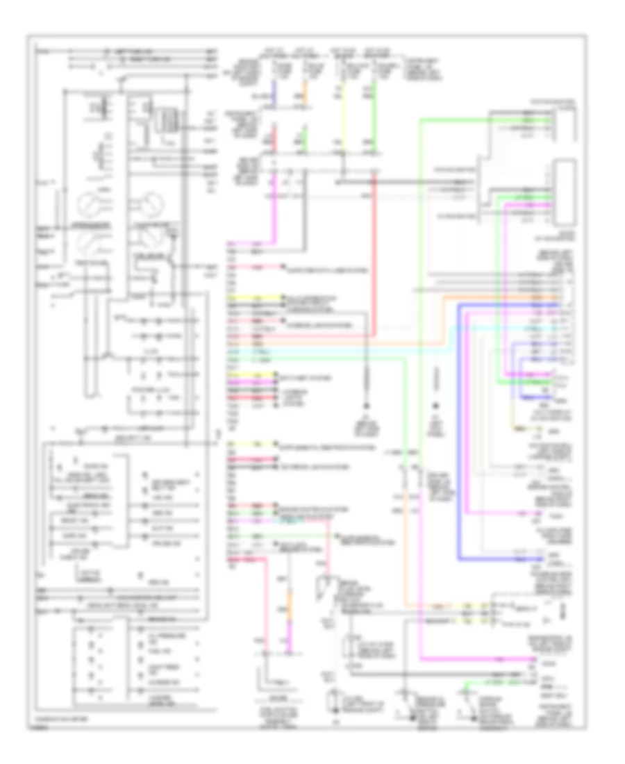
INSTRUMENT CLUSTER
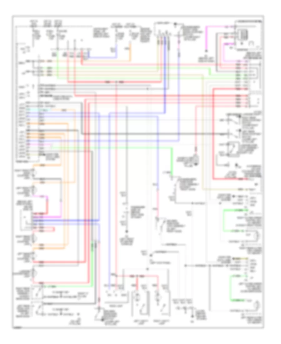
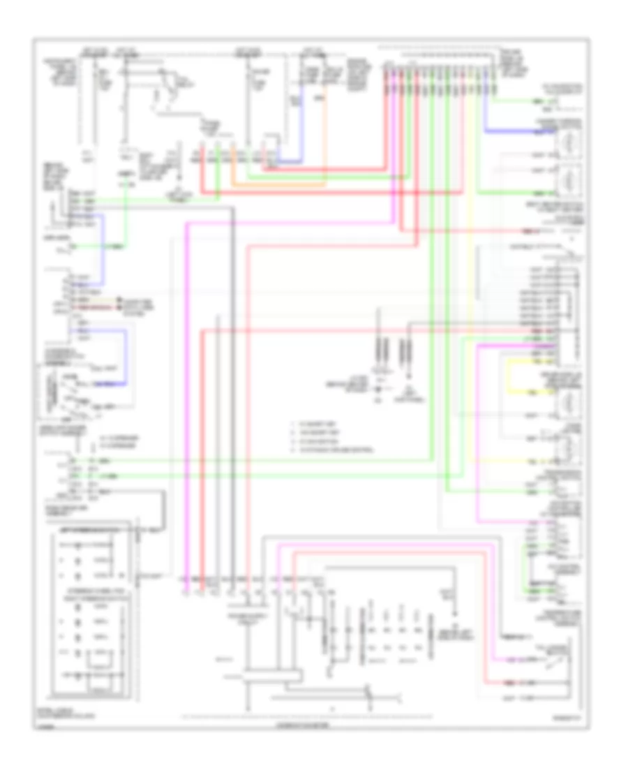
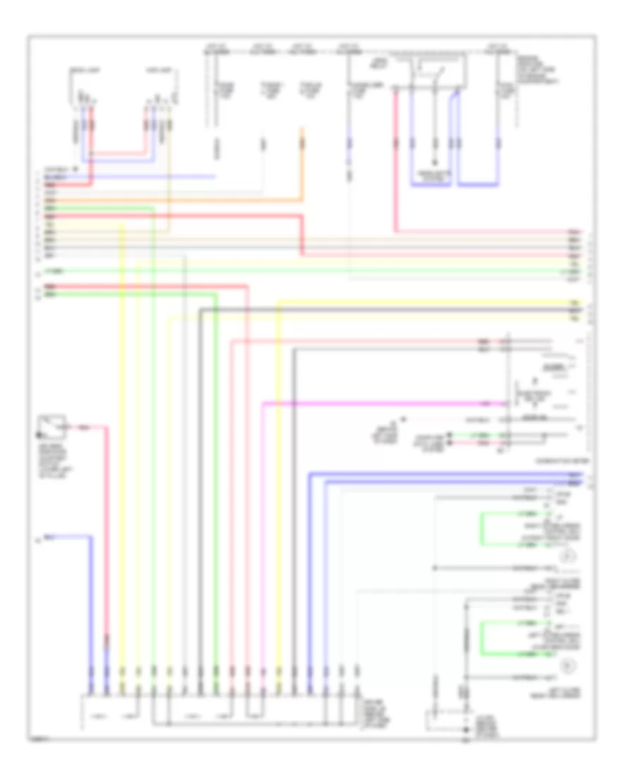
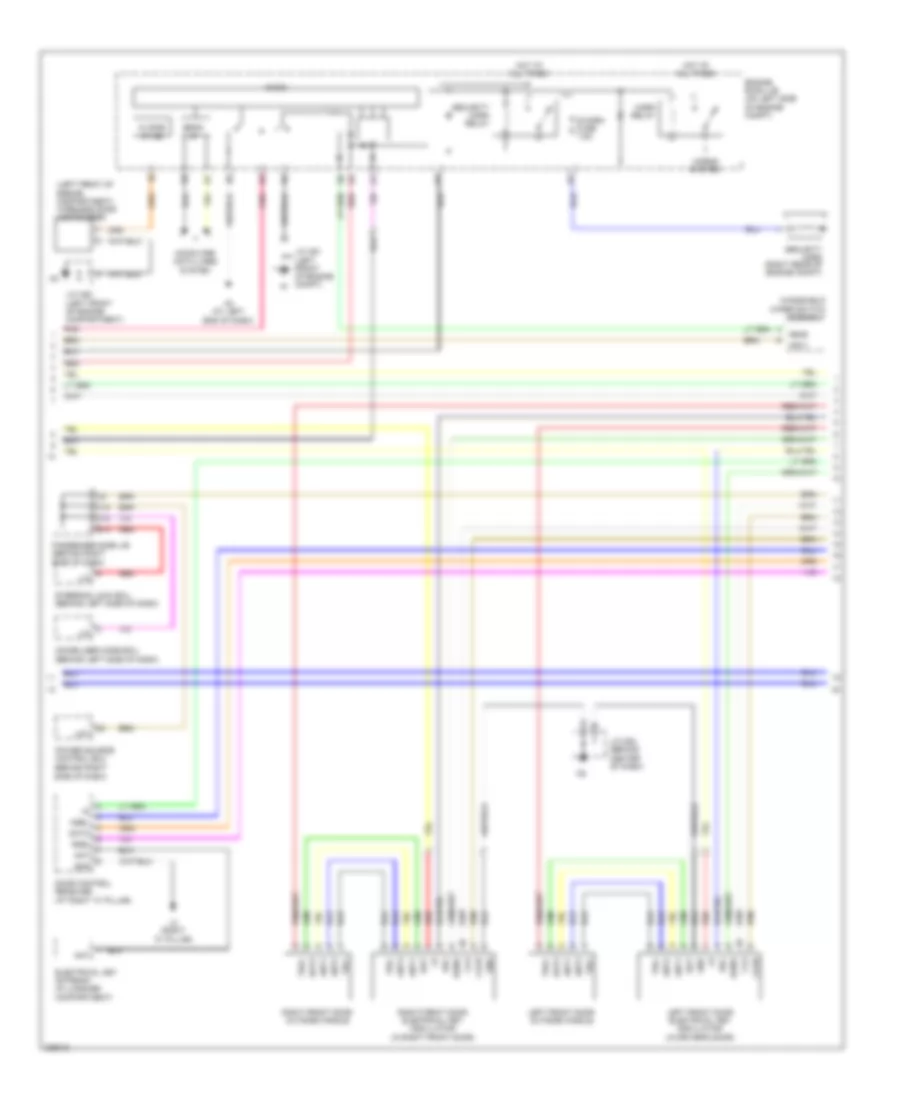
Instrument Cluster Wiring Diagram for Toyota Avalon XLS 2005
List of elements for Instrument Cluster Wiring Diagram for Toyota Avalon XLS 2005:
- (a/t range)
- (behind left side of dash) driver side j/b
- (except usa)
- (usa)
- (w/o navigation) clock
- A/c amplifier (right side of dash)
- A/o
- A10
- A11
- A12
- A13
- A14
- A15
- A16
- A17
- A18
- A19
- A20
- A21
- A22
- A23
- A24
- A41
- Abs ind
- Acan
- Active circuit
- Anti-lock brakes system
- Anti-theft system
- B10
- B11
- B12
- B13
- B14
- B15
- B16
- Beam ind
- Bean i/f
- Body ecu
- Brake fluid level warning switch (on brake fluid reservoir)
- Brake ind
- Buzzer
- C14
- Charge ind
- Check ind
- Clock (w/ navigation)
- Combination meter
- Computer data lines system
- Cruise
- Cruise ind
- D1 (left kick panel)
- D10
- D13
- D18
- D19
- D37
- D41
- D44
- D46
- Dome fuse 7.5a
- Door ind
- Driver side j/b (behind left side of dash)
- Driver's seat belt ind
- E1 (behind left side of dash)
- E25
- Ecu-acc fuse 7.5a
- Ecu-b fuse 10a
- Electronic key ind
- Engine control module (behind right side of dash)
- Engine controls system
- Engine oil pressure switch (on left side of engine)
- Engine room j/b (on left side of engine compt)
- Engine room r/b (on left side of engine compt)
- Exterior lights system
- Fuel gauge
- Fuel ind
- Fuel suction pump & gauge assembly (in fuel tank)
- G12
- Gauge
- Gauge 2 fuse 7.5a
- Head ind
- Headlight beam level ind
- Hot at all times
- Hot in on or acc
- Hot in on or start
- I10
- I11
- Illum
- Instrument panel j/b (behind left side of dash)
- Interior lights system
- J/c a41 & d46 (behind left side of dash)
- J/c a52 (left front of engine compt)
- J10
- J13
- K14
- K15
- K17
- K19
- L10
- L13
- L16
- L17
- Lcd
- Lcd (acc)
- Lcd (odo/trip)
- Led illum
- Left turn ind
- Maint reqd ind
- Malfunction ind lamp
- Micon
- Mpx +b
- Mpx1
- Multi-display (w/ navigation)
- Multi-information system circuit warning system
- Navigation ecu (left side of luggage compt)
- Norm ind
- Oil pressure ind
- P-i/p i/f (ig)
- Parking brake switch (on parking brake pedal assembly)
- Pkb
- Pnk
- Pointer illum
- Power source control ecu (behind right side of dash)
- Ready ind
- Red
- Right turn ind
- Security ind
- Slip ind
- Spd
- Speedometer
- Srs ind
- Tach
- Tachometer
- Taco
- Tail ind
- Temp gauge
- Tx1+
- Tx1-
- Vsc ind
- W/ navigation
- W/o navigation
- Washer level ind
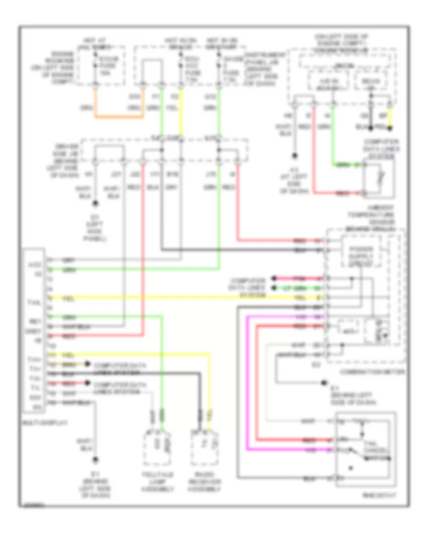
Multi-Information System Wiring Diagram for Toyota Avalon XLS 2005
List of elements for Multi-Information System Wiring Diagram for Toyota Avalon XLS 2005:
- (on left side of engine compt) engine room j/b
- A/d in (ig 0-5v)
- A/o
- A3 (at left end of dash)
- Acc
- Ambient temperature sensor (behind grille)
- B18
- Bean i/f
- Combination meter
- Computer data lines system
- D1 (left kick panel)
- D10
- D18
- Driver side j/b (behind left side of dash)
- E1 (behind left side of dash)
- Ecu- acc fuse 7.5a
- Ecu-b fuse 10a
- Engine room r/b (on left side of engine compt)
- G12
- G7 g7 g7 g7 g7
- Gauge fuse 7.5a
- Gnd1
- Hot at all times
- Hot in on or acc
- Hot in on or start
- I11
- Instrument panel j/b (behind left side of dash)
- J15
- J21
- J22
- K15
- Micon
- Mpx+b
- Msw
- Multi-display
- Pnk
- Radio receiver assembly
- Re1
- Red
- Rheostat
- Sg1
- Tail
- Tail cancel switch
- Telltale lamp assembly
- Tx+
- Tx-
- Txi+
- Txi-
INTERIOR LIGHTS
Courtesy Lamps Wiring Diagram for Toyota Avalon XLS 2005
List of elements for Courtesy Lamps Wiring Diagram for Toyota Avalon XLS 2005:
- (behind left side of dash) driver side j/b
- (right "c" pillar) l1
- - g8
- Acc
- Becu
- Body ecu
- Combination meter
- Computer data lines system
- Cpub
- Cty
- D1 (left kick panel)
- D10
- D13
- D2 (left front of center console)
- Dcty
- Dcyl
- Dome fuse 7.5a
- Door ind
- Driver's side door courtesy switch (lower left "b" pillar)
- Driver's side door lock assembly (in left front door)
- E1 (behind left side of dash)
- Ecu ig1 fuse 7.5a
- Ecu- acc fuse 7.5a
- Ecu-b fuse 10a
- Engine room r/b (on left side of engine compt)
- F10
- Gauge fuse 7.5a
- Gnd
- Gnd1
- Gnd2
- H12
- H14
- Hot at all times
- Hot in acc or on
- Hot in on or start
- I10
- I11
- Ile
- Ill+
- Ill-
- In steering column) (w/o smart key) transponder key amplifier
- Instrument panel j/b (behind left side of dash)
- J/c d53 (behind center of dash)
- J/c k32 (left side of luggage compt)
- J/c k34 (at left "c" pillar)
- K15
- K19
- K3 (on left "a" pillar)
- L10
- L16
- Lcty
- Lcyl
- Left front door courtesy lamp
- Left outer mirror control ecu (w/ memory) (in driver's door)
- Left rear door courtesy lamp
- Left rear door courtesy switch (lower left "c" pillar)
- Left rear door lock assembly (in left rear door)
- Left rear outer view mirror (w/ memory)
- Left vanity lamp
- Lgcy
- Lgyl
- Lswd
- Lswl
- Lswp
- Lswr
- Luggage compartment lamp
- Luggage door lock assembly (in luggage compt lid)
- Map lamp
- Mlp
- Mpx1
- Mpx2 d6
- Noise filter (dome & stop) (left "c" pillar)
- P10
- Passenger side j/b (behind right side of dash)
- Passenger's front side door courtesy switch (lower right "b" pillar)
- Passenger's side door lock assembly (in right front door)
- Pcty
- Pcyl
- Pnk
- R6 red
- Rcty
- Rcyl d8
- Red
- Right front door courtesy lamp
- Right outer mirror control ecu (w/ memory) (in right front door)
- Right rear door courtesy lamp
- Right rear door courtesy switch (lower right "c" pillar)
- Right rear door lock assembly (in right rear door)
- Right rear outer view mirror (w/ memory)
- Right vanity lamp
- Room lamp
- Sel1
- W/ smart key
Instrument Illumination Wiring Diagram for Toyota Avalon XLS 2005
List of elements for Instrument Illumination Wiring Diagram for Toyota Avalon XLS 2005:
- (behind left side of dash) driver side j/b
- (w/ navigation) multi-display
- A/c control assembly
- A/o
- A12
- B12
- B13
- Body ecu (attached to driver side j/b)
- C12
- C13
- Cigar lighter
- Cill
- Combination meter
- Computer data lines system
- Cspt
- D1 (left kick panel)
- D10
- D13
- Dome fuse 7.5a
- Driver side j/b (behind left side of dash)
- E1 (behind left side of dash)
- E12
- E13
- E14
- E15
- E25
- Eau
- Ecu b fuse 10a
- Ecu ig 1 fuse 7.5a
- Engine room r/b (on left side of engine compt)
- F10
- F11
- F13
- F14
- F19
- G12
- G17
- G18
- Gauge fuse 7.5a
- Glove box lamp
- Gnd
- Hazard warning signal switch
- Head
- Headlamp dimmer switch assembly
- Hot at all times
- Hot in on or start
- I10
- I11
- Il+2
- Ill+
- Ill-
- Illumination
- Instrument panel j/b (behind left side of dash)
- J/c d53 (behind center of dash)
- K15
- K19
- L10
- Led illumination
- Left steering switch
- Map lamp
- Mpx1
- Mpx2
- Navigation controller (w/ navigation)
- Off
- Panel fuse 7.5a
- Pil+
- Pil-
- Pointer illumination
- Pse
- Radio receiver assembly
- Red
- Rheostat
- Right steering switch
- Seat heater switch (w/ seat heater)
- Spiral cable (on steering column)
- Steering wheel pad
- Switch light control
- Tail
- Tail cancel switch
- Tail relay
- Temperature control switch assembly
- Transmission control switch
- Trly
- W/ 12 speaker
- W/ 9 speaker
- W/ dynamic cruise control
- W/ navigation
- W/ smart key
- W/o smart key
- Windshield dimmer switch assembly
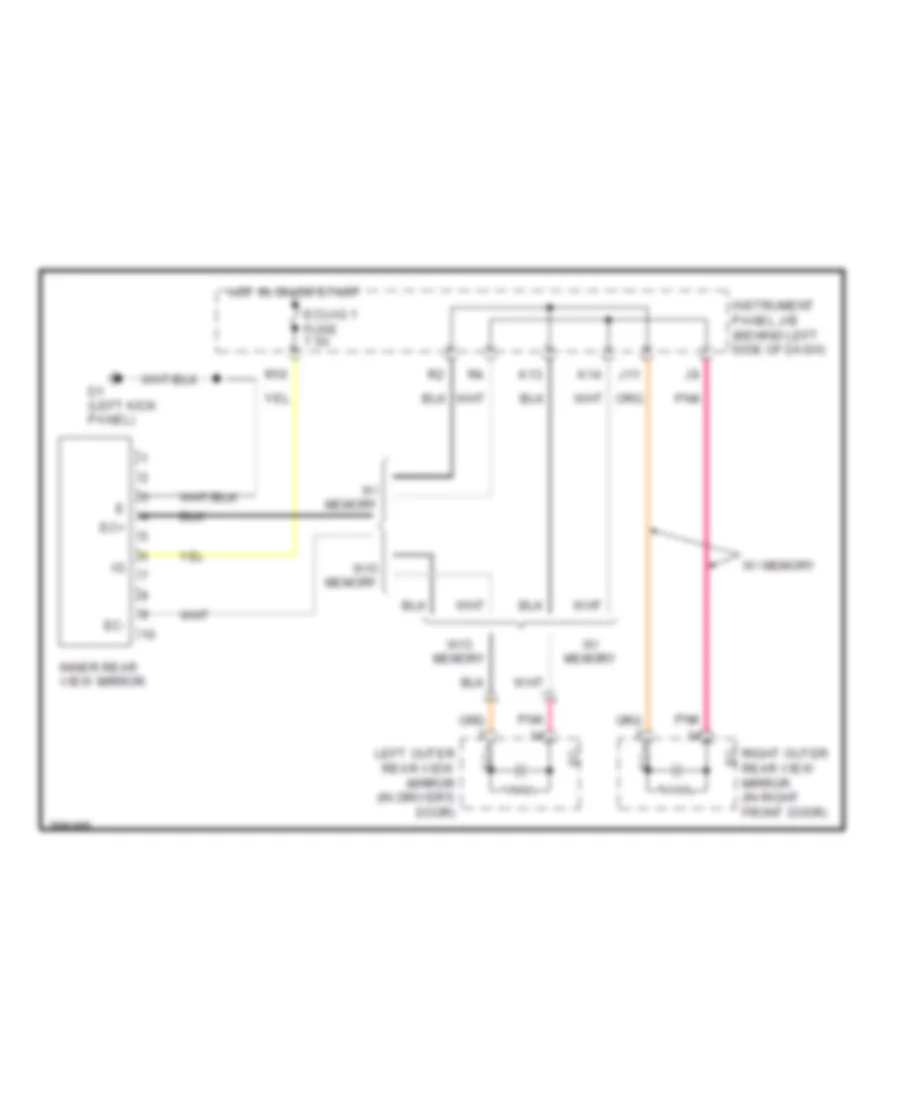
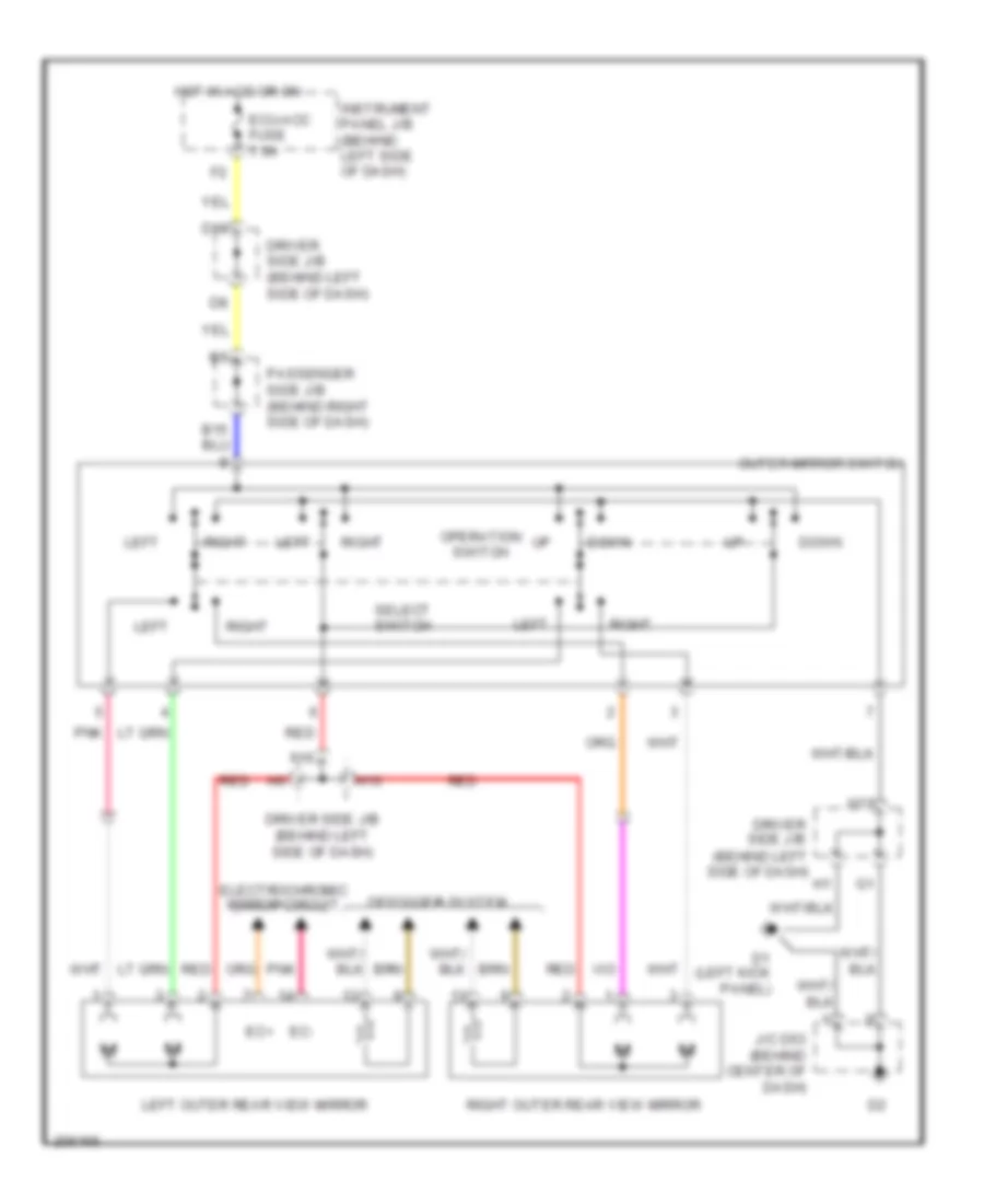
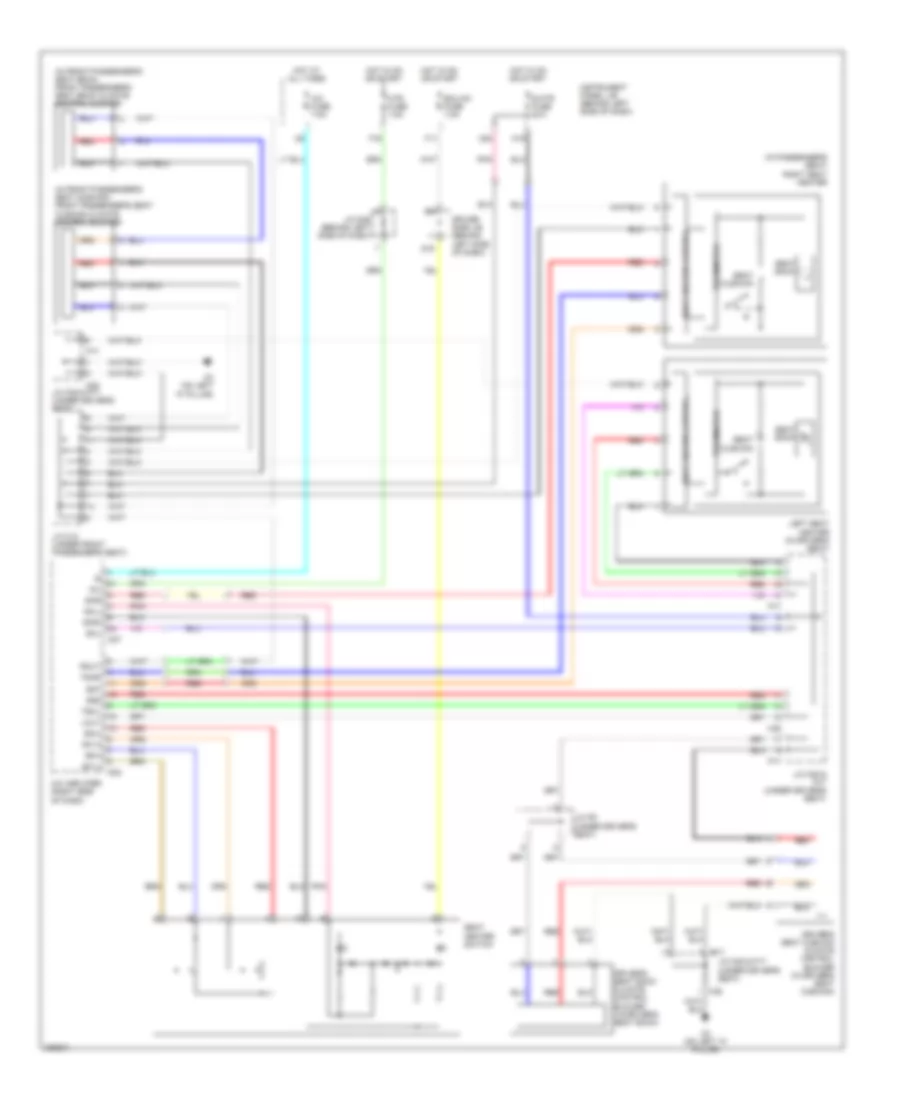
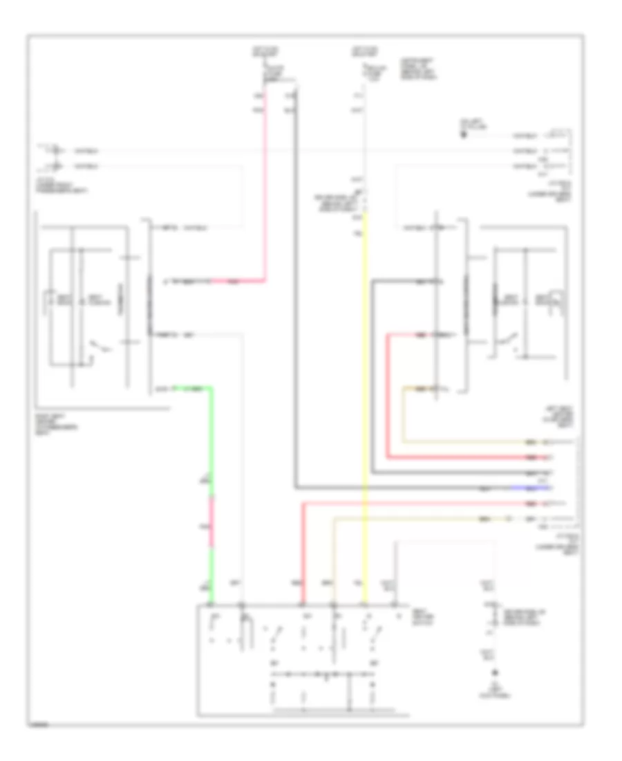
MEMORY SYSTEMS
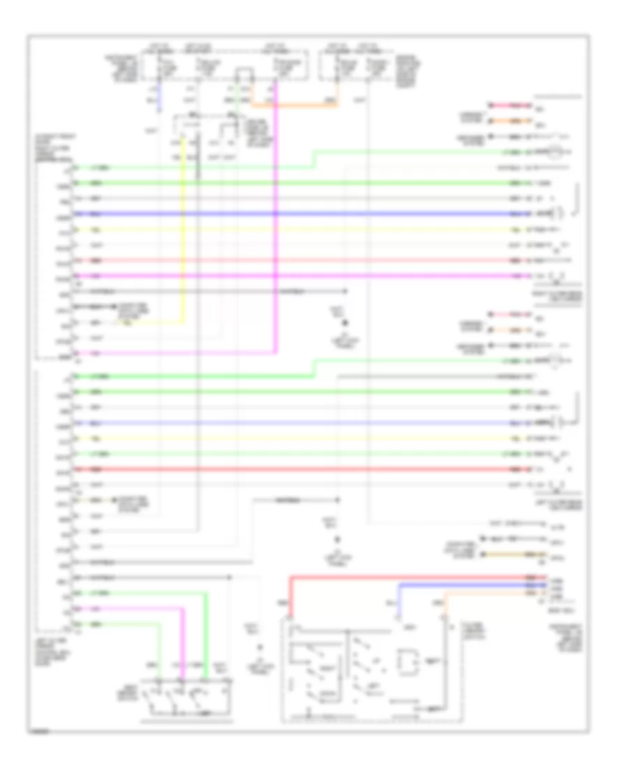
Memory Mirrors Wiring Diagram for Toyota Avalon XLS 2005
List of elements for Memory Mirrors Wiring Diagram for Toyota Avalon XLS 2005:
- (in right front door) right outer mirror control ecu
- Altb
- Bdr
- Body ecu
- Computer data lines system
- Cpub
- D1 (left kick panel)
- D10
- D16
- De2
- Defogger system
- Dm+r
- Dmhr
- Dmvr
- Door 1 fuse 25a
- Down
- Driver side j/b (behind left side of dash)
- Dvc
- Ec+
- Ec-
- Ecu-b fuse 10a
- Ecu-ig1 fuse 7.5a
- Engine room r/b (on left side of engine compt)
- F11
- Fr door fuse 25a
- Gnd
- H14
- H19
- Hot at all times
- Hot in on or start
- Hsrl
- Hssr
- Instrument panel j/b (behind left side of dash)
- L12
- Left
- Left outer mirror control ecu (in driver's door)
- Left outer rear view mirror
- Mirb
- Mire
- Mirrors system
- Mirs
- Mlp
- Mpx1
- Mpx2
- Mry
- Msw
- Outer memory switch
- P/w fuse 25a
- Pe2
- Pm+r
- Pmhr
- Pmvr
- Pnk
- Pvc
- Red
- Right
- Right outer rear view mirror
- Seat memory switch
- Sel1
- Set
- Sig
- Vsrl
- Vssr
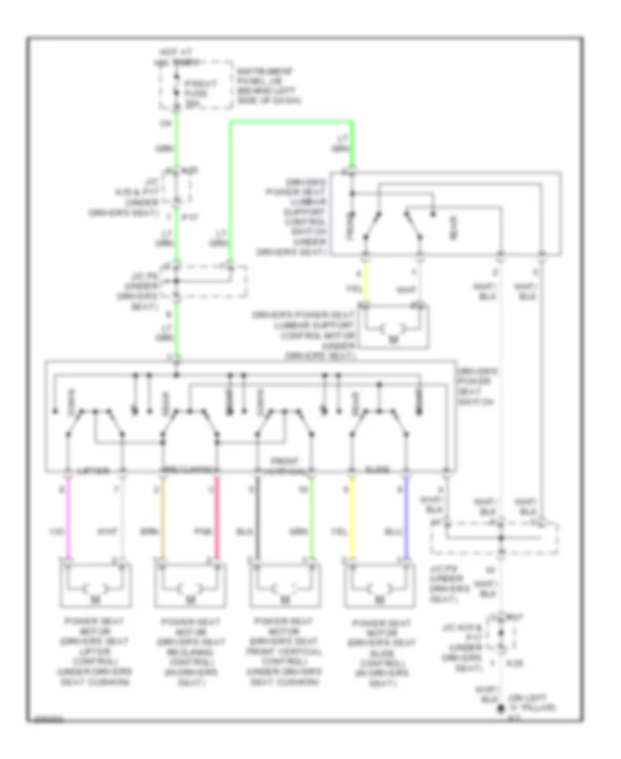
Memory Seat Wiring Diagram for Toyota Avalon XLS 2005
List of elements for Memory Seat Wiring Diagram for Toyota Avalon XLS 2005:
- (left kick panel) d1
- Computer data lines system
- Cpub
- D10
- Driver side j/b (behind left side of dash)
- Ecu ig1 fuse 7.5a
- Ecu-b fuse 10a
- Engine room r/b (on left side of engine compt)
- F11
- Front
- Frv+
- Frv-
- Gnd
- Hot at all times
- Hot in on or start
- Instrument panel j/b (behind left side of dash)
- J/c p9 (under driver's seat)
- Junction connector k35 & p17 (under driver's seat)
- K3 (on left "a" pillar)
- K35
- Left outer mirror control ecu (in driver's door)
- Lft+
- Lft-
- Mpx1
- Mry
- P/seat fuse 30a
- P13
- P14
- P17
- Pnk
- Position control ecu & switch (left side of driver's seat)
- Power seat motor (driver's seat front vertical control) (under driver's seat cushion)
- Power seat motor (driver's seat leg support control) (under driver's seat)
- Power seat motor (driver's seat lifter control) (under driver's seat cushion)
- Power seat motor (driver's seat lumber support control) (under driver's seat)
- Power seat motor (driver's seat reclining control) (in driver's seat)
- Power seat motor (driver's seat slide control) (in driver's seat)
- Power seat switch (driver's seat leg support control)
- Power seat switch (driver's seat lumbar support control)
- Rcl+
- Rcl-
- Rear
- Seat memory switch
- Sel1
- Set
- Sig
- Sld+
- Sld-
- Sysb
NAVIGATION
Navigation Wiring Diagram (1 of 2) for Toyota Avalon XLS 2005
List of elements for Navigation Wiring Diagram (1 of 2) for Toyota Avalon XLS 2005:
- (behind glove box) junction connector b48 & d47
- (on transaxle) park/neutral position switch
- A34
- A40
- Acc
- Aui+
- Aui-
- Auo+
- Auo-
- B48
- Combination meter
- Computer data lines system
- D10
- D47
- Driver side j/b (behind left side of dash)
- E1 (behind left side of dash)
- G12
- Gauge 1 fuse 10a
- Gauge 2 fuse 7.5a
- Gnd1
- H16
- Hot in on or start
- I11
- Instrument panel j/b (behind left side of dash)
- J13
- Junction connector e29 (behind center of dash)
- K15
- L16
- L17
- L18
- L2 (right "c" pillar)
- Left front door speaker
- Left front tweeter
- Macc
- Mi1+
- Mic+
- Mic-
- Microphone (navigation) (front of roof)
- Navigation ecu (left side of luggage compt)
- Nca
- Pnk
- Red
- Rev
- Sgnd
- Skid control ecu w/ actuator
- Snse
- Spd
- Speedometer
- Sync
- Twl+
- Twl-
- Tx1+
- Tx1-
- W/ vsc
- W/o vsc
Navigation Wiring Diagram (2 of 2) for Toyota Avalon XLS 2005
List of elements for Navigation Wiring Diagram (2 of 2) for Toyota Avalon XLS 2005:
- (on parking brake pedal assembly) parking brake switch
- +b1
- A14
- A17
- A20
- Acc
- Atx+
- Atx-
- B10
- C10
- C14
- C15
- C17
- Computer data lines system
- D10
- D16
- Driver side j/b (behind left side of dash)
- E12
- E15
- E19
- E20
- E25
- Ecu ig1 fuse 7.5a
- Ecu-b fuse 10a
- Engine room r/b (on left side of engine compt)
- F11
- F12
- Fl+
- Fl-
- Gnd
- Gnd1
- Gnd2
- Gnd3
- Gnd4
- Gnd5
- Hot at all times
- Hot in on or acc
- Hot in on or start
- Ill+
- Ill-
- Instrument panel j/b (behind left side of dash)
- Interior lights system
- Junction connector d53 (behind center of dash)
- Junction connector e29 (behind center of dash)
- Multi-display
- Navigation controller
- Nca
- Pkb
- Pnk
- Rad 1 fuse 15a
- Radio 2 fuse 7.5a
- Radio receiver assembly (12 speaker)
- Re1
- Red
- Sgd1
- Sgd2
- Sgnd
- Spd
- Stereo component amplifier (12 speaker) (under front passenger's seat)
- Sync
- Tx+
- Tx-
- Tx1+
- Tx1-
- Tx2+
- Tx2-
- Tx4+
- Tx4-
POWER DISTRIBUTION
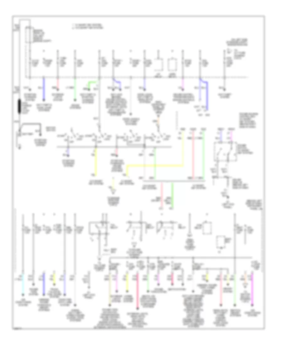
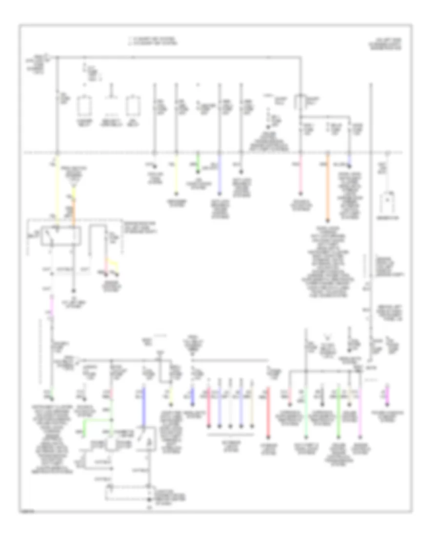
Power Distribution Wiring Diagram (1 of 2) for Toyota Avalon XLS 2005
List of elements for Power Distribution Wiring Diagram (1 of 2) for Toyota Avalon XLS 2005:
- (behind left side of dash) instrument panel j/b
- (on left side of engine compt) engine room r/b
- A/c comp fuse 7.5a
- A/c fuse 7.5a
- A/f relay
- Acc
- Acc relay
- Accd
- Air conditioning system
- Alt-s fuse 7.5a
- Am1
- Am1 fuse 7.5a
- Am2
- Am2 fuse 7.5a
- Amp fuse 30a
- Anti-lock brakes, cruise control, engine controls, shift interlock, exterior lights anti-theft & transmissions systems
- Anti-lock brakes, wiper/washer, seats, memory, cruise control, transmissions, headlights, interior lights navigation, computer data lines, power windows, mirrors, horns & shift interlock systems
- Anti-theft & door locks systems
- Anti-theft & starting/ charging systems
- Anti-theft system
- Battery
- Body ecu
- C12
- Computer data lines system
- Cruise control, transmissions & engine controls systems
- D1 (left kick panel)
- D15
- Door 1 fuse 25a
- Door locks & anti-theft systems
- Door locks, anti-theft & headlights systems
- Driver side j/b (behind left side of dash)
- Ecu ig 1 fuse 7.5a
- Ecu ig 2 fuse 10a
- Engine room j/b (on left side of engine compt)
- Etcs fuse 10a
- Exterior lights system
- Exterior lights, headlights, anti-lock brakes & cruise control systems
- F10
- F11
- F14
- F16
- F19
- From door 2 fuse (diagram 2 of 2)
- From instrument panel j/b (diagram 1 of 2)
- Fuel opn fuse 7.5a
- Gauge 1 fuse 10a
- H16
- Headlights, anti-theft, wiper/ washer, horns & door locks system
- Horn relay
- Horns, anti-theft, wiper/washer & door locks systems
- Htr fuse 7.5a
- Ig1 relay
- Ig1d
- Ig2d
- Ignition switch
- Immobi fuse 7.5a
- L12
- Lock
- M18
- M19
- M20
- Main fuse 40a
- Memory system
- Mirrors, power tops, wiper/ washer systems
- Mirrors, power windows & memory systems
- Mpx-b fuse 7.5a
- Nca
- Obd fuse 7.5a
- Off
- P/ seat fuse 30a
- P/w fuse 25a
- Pnk
- Power source control ecu (w/ smart key system) (behind right side of dash)
- Power switch (w/ smart key system)
- Power tops system
- Power tops, navigation, transmissions, cruise control, door locks, engine controls, starting/charging & exterior lights systems
- Pwr relay
- R10
- R12
- Red
- Rr s/shade fuse 10a
- S-htr fuse 20a
- S/ roof fuse 30a
- Seats & memory systems
- Seats system
- Seats, air conditioning, cooling fans & defogger systems
- Sound systems
- Ssw1
- Ssw2
- St/ am2 fuse 30a
- Start
- Starting/ charging & cruise control systems
- Starting/ charging system
- Stop 1 fuse 15a
- Str lock fuse 25a
- Tail relay
- To alt fuse (diagram 2 of 2)
- To engine room r/b (diagram 2 of 2)
- To ignition switch (diagram 1 of 2)
- To power outlet fuse (diagram 2 of 2)
- To tail fuse (diagram 2 of 2)
- Trly
- Trunk, tailgate, fuel doors system
- Turn/ haz fuse 15a
- W/ smart key system
- W/o smart key system
- Wip fuse 30a
- Wiper/ washer system
Power Distribution Wiring Diagram (2 of 2) for Toyota Avalon XLS 2005
List of elements for Power Distribution Wiring Diagram (2 of 2) for Toyota Avalon XLS 2005:
- (behind left side of dash) instrument panel j/b
- (on left side of engine compt) engine room r/b
- A3 (at left end of dash)
- Abs/ vcs 1 fuse 50a
- Abs/ vsc 2 fuse 30a
- Acc
- Air conditioning system
- Alt fuse 140a 120a
- Anti-lock brakes & cruise control systems
- Anti-theft & door locks systems
- Batb
- Body ecu
- Cig fuse 15a
- Cigarette lighter
- Computer data lines, instrument cluster, door locks, navigation, anti-theft, mirrors & shift interlock systems
- Cooling fans system
- Cruise control system
- Cruise control, engine controls & transmissions system
- Cruise control, transmissions, engine controls & anti-theft systems
- D14
- Defogger system
- Dome fuse 7.5a
- Door fuse 25a
- Door locks, instrument cluster, headlights, interior lights, garage door opener, exterior lights & anti-theft systems
- Drl relay
- Ecu- acc fuse 7.5a
- Ecu-b fuse 10a
- Efi 1 fuse 25a
- Engine controls system
- Engine room j/b (on left side of engine compt)
- Engine room r/b (on left side of engine compt)
- Exterior lights system
- F12
- Fog fuse 15a
- Fr door fuse 25a
- From acc relay d (diagram 1 of 2)
- From ignition switch (diagram 1 of 2)
- From str lock fuse (diagram 1 of 2)
- From tail relay (diagram 1 of 2)
- G12
- Gauge 2 fuse 7.5a
- Generator
- Headlights system
- Heater fuse 50a
- Ig2 fuse 25a
- Ig2 relay
- Ign fuse 10a
- Inj fuse 15a
- Interior lights system
- Junction connector d53 (behind center of dash)
- M10
- M13
- M14
- M16
- Panel fuse 7.5a
- Pnk
- Power outlet
- Power windows & memory system
- Pwr outlet fuse 15a
- Rad 1 fuse 15a
- Radio fuse 7.5a
- Rdi fan fuse 50a
- Red
- Rr def fuse 50a
- Security horn relay
- Short pin 1
- Short pin 2
- Sound & navigation system
- Sound & navigation systems
- Tail fuse 10a
- To acc relay 2 (diagram 1 of 2)
- W/ smart key system
- W/o smart key system
- Washer relay
POWER DOOR LOCKS
Power Door Locks Wiring Diagram, with Smart Key System (1 of 4) for Toyota Avalon XLS 2005
List of elements for Power Door Locks Wiring Diagram, with Smart Key System (1 of 4) for Toyota Avalon XLS 2005:
- (behind right side of dash) passenger side j/b
- (left kick panel) d1
- Acc
- Act+
- Act-
- Actd
- Altb
- B18
- B48
- Batb
- Becu
- Body ecu
- Canh
- Canl
- Computer data lines system
- D10
- D13
- D16
- D2 (left front of center console)
- D47
- Dcty
- Door 2 fuse 25a
- Driver's side door lock assembly (in left front door)
- Ecu-acc fuse 7.5a
- Ecu-ig 1 fuse 7.5a
- Engine control module (behind right side of dash)
- Exterior lights system
- F10
- F18
- Front passenger's side door courtesy switch (lower right "b" pillar)
- Front passenger's side door lock assembly (in right front door)
- G12
- Gauge 1 fuse 10a
- Gauge 2 fuse 7.5a
- Gnd1
- Gnd2
- H16
- Haz
- Hot at all times
- Hot in acc or on
- Hot in on or start
- Ign fuse 10a
- Ile
- Instrument panel j/b (behind left side of dash)
- J/c b48 & d47 (behind glove box)
- J/c d53 (behind center of dash)
- J/c k34 (at left "c" pillar)
- K3 (on left "a" pillar)
- L1 (right "c" pillar)
- L10
- Lcty
- Left rear door courtesy switch (lower left "c" pillar)
- Left rear door lock assembly (in left rear door)
- Lgcy
- Lswd
- Lswl
- Lswp
- Lswr
- Luggage door lock assembly (in luggage compt lid)
- M18
- Mpx-b fuse 7.5a
- Mpx1
- Mpx2
- P11
- Park/neutral position switch (on transaxle)
- Pcty
- Pnk
- Rcty
- Red
- Right rear door courtesy switch (lower right "c" pillar)
- Right rear door lock assembly (in right rear door)
- Tail relay
- Tr+
- Trly
- Turn signal flasher (behind left side of dash)
Power Door Locks Wiring Diagram, with Smart Key System (2 of 4) for Toyota Avalon XLS 2005
List of elements for Power Door Locks Wiring Diagram, with Smart Key System (2 of 4) for Toyota Avalon XLS 2005:
- Buzzer
- Combination meter
- Computer data lines system
- Cpub
- Cty
- D18
- Dome fuse 7.5a
- Door 1 fuse 25a
- Door ind
- Driver side j/b (behind left side of dash)
- Driver's side door courtesy switch (lower left "b" pillar)
- E1 (behind left side of dash)
- Ecu-b fuse 10a
- Electronic key ind
- Engine room r/b (on left side of engine compartment)
- Gnd
- Gnd1
- H14
- H15
- Head relay
- Headlights system
- Hot at all times
- I11
- Immobilizer fuse 7.5a
- J/c d53 (behind center of dash)
- K15
- K18
- K19
- L16
- Left outer mirror control ecu (in driver's door)
- Left outer rear view mirror
- Main fuse 40a
- Map lamp
- Pnk
- Red
- Right outer mirror control ecu (in right front door)
- Right outer rear view mirror
- Room lamp
- Sel 1
Power Door Locks Wiring Diagram, with Smart Key System (3 of 4) for Toyota Avalon XLS 2005
List of elements for Power Door Locks Wiring Diagram, with Smart Key System (3 of 4) for Toyota Avalon XLS 2005:
- (behind right side of dash)
- (left front of engine compartment) wireless door lock buzzer
- A3 (at left end of dash)
- Ant
- Ant1
- Ant2
- Asel
- Assembly
- B14
- Bean i/f
- C14
- Clg
- Clgb
- Computer data lines system
- D14
- Data
- Door control receiver (at right "c" pillar)
- Electrical key antenna (in luggage compartment)
- Engine room j/b (on left side of engine compt)
- Gnd
- Head
- Horn relay
- Horns system
- Hot at all times
- Immobilizer code ecu (behind left side of dash)
- J/c a51 (left front of engine compt)
- J/c a52 (left front of engine compartment)
- J/c d53 (behind center of dash)
- L2 (right "c" pillar)
- Left front door electrical key oscillator (in driver's door)
- Left front door outside handle
- Lin
- Lin1
- Mi side i/f (+b)
- Micon
- Mpx1
- Passenger side j/b (behind right side of dash)
- Pnk
- Power source control ecu
- Red
- Right front door electrical key oscillator (in right front door)
- Right front door outside handle
- Rssi
- S-horn fuse 7.5a
- Security horn (right rear of engine compt)
- Security horn relay
- Sel
- Sens
- Sgt
- Sgt2
- Steering lock ecu (behind left side of dash)
- Trg+
- Trg-
- Windshield
- Wiper switch
Power Door Locks Wiring Diagram, with Smart Key System (4 of 4) for Toyota Avalon XLS 2005
List of elements for Power Door Locks Wiring Diagram, with Smart Key System (4 of 4) for Toyota Avalon XLS 2005:
- (at left "c" pillar) j/c k34
- (behind right side of dash) passenger side j/b
- (behind right side of rear bumper) electrical key oscillator (outside luggage room)
- (center console) electrical key oscillator (console)
- (in luggage compartment) electrical key oscillator (inside luggage room)
- (left front of center console) d2
- (under rear seat) electrical key oscillator (rear seat)
- +b1
- Acc
- Ant1
- Ant2
- Asel
- Cg1b
- Cg2b
- Cg3b
- Cg4b
- Cg5b
- Cg6b
- Cg7b
- Cg8b
- Clg
- Clg1
- Clg2
- Clg3
- Clg4
- Clg5
- Clg6
- Clg7
- Clg8
- Clgb
- Computer data lines system
- D39
- D40
- Gnd
- K3 (on left "a" pillar)
- L1 (right "c" pillar)
- Left rear door electrical key oscillator (in left rear door)
- Left rear door outside handle
- Lin
- Luggage electrical key switch (in luggage compt lid)
- Mpx1
- Mpx2
- Pnk
- Rco
- Rda
- Red
- Right rear door electrical key oscillator (in right rear door)
- Right rear door outside handle
- Rssi
- Sel
- Sel1
- Sel2
- Sel3
- Sel4
- Sen1
- Sen2
- Sen3
- Sen4
- Sens
- Sgt
- Sgt2
- Smart key ecu (behind right side of dash)
- Trg+
- Trg-
- Tsw1
- Tsw2
- Tsw3
- Tsw4
- Tsws
Power Door Locks Wiring Diagram, without Smart Key System (1 of 2) for Toyota Avalon XLS 2005
List of elements for Power Door Locks Wiring Diagram, without Smart Key System (1 of 2) for Toyota Avalon XLS 2005:
- (left kick panel) d1
- (lower right "c" pillar)
- 16k
- Acc
- Act+
- Act-
- Actd
- Altb
- B18
- Batb
- Becu
- Body ecu
- Computer data lines system
- Cty
- D10
- D13
- D16
- D2 (left front of center console)
- Dcty
- Dome fuse 7.5a
- Door 1 fuse 25a
- Door 2 fuse 25a
- Driver's side door lock assembly (in left front door)
- Ecu-acc fuse 7.5a
- Ecu-b fuse 10a
- Ecu-ig 1 fuse 7.5a
- Engine room r/b (on left side of engine compartment)
- Exterior lights system
- F10
- F18
- Front passenger's side door courtesy switch (lower right 'b" pillar)
- G12
- Gauge 1 fuse 10a
- Gauge 2 fuse 7.5a
- Gnd1
- Gnd2
- H16
- Haz
- Head relay
- Headlights system
- Hot at all times
- Hot in acc or on
- Hot in on or start
- I10
- Ile
- Instrument panel j/b (behind left side of dash)
- J/c d53 (behind center of dash)
- J/c k34 (at left "c" pillar)
- K3 (on left "a" pillar)
- Ksw
- L1 (right "c" pillar)
- L10
- Lcty
- Left rear door courtesy switch (lower left "c" pillar)
- Left rear door lock assembly (in left rear door)
- Lgcy
- Lock
- Lswd
- Lswl
- Lswp
- Lswr
- Luggage door lock assembly (in luggage compt lid)
- M18
- Main fuse 40a
- Map lamp
- Mpx-b fuse 7.5a
- Mpx1
- Mpx2
- P11
- Passenger side j/b (behind right side of dash)
- Pcty
- Pnk
- Prg
- Rcty
- Rda
- Red
- Right rear door courtesy switch
- Right rear door lock assembly (in right rear door)
- Room lamp
- Tail relay
- Tr+
- Trly
- Turn signal flasher (behind left side of dash)
- Ul2
- Ul3
- Unlock
Power Door Locks Wiring Diagram, without Smart Key System (2 of 2) for Toyota Avalon XLS 2005
List of elements for Power Door Locks Wiring Diagram, without Smart Key System (2 of 2) for Toyota Avalon XLS 2005:
- (behind left side of dash) e1
- (behind right side of dash) passenger side j/b
- (left front of engine compt) wireless door lock buzzer
- (right "c" pillar) l2
- A3 (at left end of dash)
- B48
- Bean i/f
- Buzzer
- Canh
- Canl
- Combination meter
- Computer data lines system
- D1 (left kick panel)
- D10
- D20
- D47
- Door control receiver (at right "c" pillar)
- Door ind
- Driver side j/b (behind left side of dash)
- Driver's side door courtesy switch (lower left "b" pillar)
- E14
- Engine control module (behind right side of dash)
- Engine room j/b (on left side of engine compartment)
- Front passenger's side door lock assembly (in right front door)
- Gateway ecu (behind right side of dash)
- Gnd
- Head
- Horn relay
- Horns system
- Hot at all times
- I11
- J/c a51 (left front of engine compt)
- J/c a52 (left front of engine compt)
- J/c b48 & d47 (behind glove box)
- J/c d53 (behind center of dash)
- K14
- K15
- K18
- K19
- L10
- L11
- L16
- L22
- Mi side i/f (+b)
- Micon
- Mpd2
- Park/neutral position switch (on transaxle)
- Pnk
- Prg
- Rda
- Red
- S-horn fuse 7.5a
- Security horn (right rear of engine compt)
- Security horn relay
- Transponder key amplifier (in steering column)
- Unlock warning switch (lower left side of dash)
- Windshield wiper switch assembly
POWER MIRRORS
Electrochromic Mirror Wiring Diagram for Toyota Avalon XLS 2005
List of elements for Electrochromic Mirror Wiring Diagram for Toyota Avalon XLS 2005:
- D1 (left kick panel)
- Ec+
- Ec-
- Ecu-ig 1 fuse 7.5a
- Hot in on or start
- Inner rear view mirror
- Instrument panel j/b (behind left side of dash)
- J11
- K13
- K14
- Left outer rear view mirror (in driver's door)
- Pnk
- R10
- Right outer rear view mirror (in right front door)
- W/ memory
- W/o memory
Power Mirrors Wiring Diagram for Toyota Avalon XLS 2005
List of elements for Power Mirrors Wiring Diagram for Toyota Avalon XLS 2005:
- D1 (left kick panel)
- D18
- Defogger system
- Down
- Driver side j/b (behind left side of dash)
- Ec+
- Ec-
- Ecu-acc fuse 7.5a
- Electrochromic mirror circuit
- F16
- H11
- H16
- Hot in acc or on
- Instrument panel j/b (behind left side of dash)
- J/c d53 (behind center of dash)
- Left
- Left outer rear view mirror
- Operation switch
- Outer mirror switch
- Passenger side j/b (behind right side of dash)
- Pnk
- Red
- Right
- Right outer rear view mirror
- Select switch
POWER SEATS
Driver Power Seat Wiring Diagram for Toyota Avalon XLS 2005
List of elements for Driver Power Seat Wiring Diagram for Toyota Avalon XLS 2005:
- (on left "a" pillar) k3
- Down
- Driver's power seat lumbar support control motor (under driver's seat)
- Driver's power seat lumbar support control switch (under driver's seat)
- Driver's power seat switch
- Front
- Front vertical
- Hot at all times
- Instrument panel j/b (behind left side of dash)
- J/c k35 & p17 (under driver's seat)
- J/c p9 (under driver's seat)
- K35
- Lifter
- P/seat fuse 30a
- P17
- Pnk
- Power seat motor (driver's seat front vertical control) (under driver's seat cushion)
- Power seat motor (driver's seat lifter control) (under driver's seat cushion)
- Power seat motor (driver's seat reclining control) (in driver's seat)
- Power seat motor (driver's seat slide control) (in driver's seat)
- Rear
- Reclining
- Slide
Heated Seats Wiring Diagram, with Climate Control Seat for Toyota Avalon XLS 2005
List of elements for Heated Seats Wiring Diagram, with Climate Control Seat for Toyota Avalon XLS 2005:
- (in front passenger's seat back) front passenger's seat back climate control blower
- (in front passenger's seat cushion) front passenger's seat cushion climate control blower
- (in passenger's seat) right seat heater
- A/c amplifier (right side of dash)
- A/c fuse 7.5a
- D37
- D38
- Driver side j/b (behind left side of dash)
- Driver's seat back climate control blower (in driver's seat back)
- Driver's seat cushion climate control blower (in driver's seat cushion)
- Ecu-ig1 fuse 7.5a
- F11
- F16
- G19
- Hot at all times
- Hot in on or start
- Htr fuse 7.5a
- Ig+
- Instrument panel j/b (behind left side of dash)
- J/c d46 (behind left side of dash)
- J/c k35 & p17 (under driver's seat)
- J/c o12 (under front passenger's seat)
- J/c p9 (under driver's seat)
- K3 (on left "a" pillar)
- K35
- Left seat heater (in driver's seat)
- Lout
- M19
- M20
- P17
- Pnk
- Red
- Rout
- S-htr fuse 20a
- S5-4
- Scli
- Scri
- Seat back
- Seat cushion
- Seat heater control
- Seat heater switch
- Sg-4
- Sg7
- Sg8
- Shl
- Shr
- Sw 4
- Sw 5
- Thermistor
- Tshl
- Tshr
Heated Seats Wiring Diagram, without Climate Control Seat for Toyota Avalon XLS 2005
List of elements for Heated Seats Wiring Diagram, without Climate Control Seat for Toyota Avalon XLS 2005:
- (on left "a" pillar) k3
- D1 (left kick panel)
- Driver side j/b (behind left side of dash)
- Ecu-ig1 fuse 7.5a
- F11
- G13
- G19
- Hot in on or start
- Instrument panel j/b (behind left side of dash)
- J/c k35 & p17 (under driver's seat)
- J/c o12 (under front passenger's seat)
- K35
- Left seat heater (in driver's seat)
- M19
- M20
- P17
- Pnk
- Red
- Right seat heater (in passenger's seat)
- S-htr fuse 20a
- Seat back
- Seat cushion
- Seat heater control
- Seat heater switch
- Swl
- Swr
- Thermistor
- Thl
- Thr
Passenger Power Seat Wiring Diagram for Toyota Avalon XLS 2005
List of elements for Passenger Power Seat Wiring Diagram for Toyota Avalon XLS 2005:
- Front
- Front passenger's power seat switch
- Hot at all times
- Instrument panel j/b (behind left side of dash)
- J/c k35 (under driver's seat)
- J/c o12 (under front passenger's seat)
- K3 (on left "a" pillar)
- P/seat fuse 30a
- Pnk
- Power seat motor (front passenger's seat reclining control) (in front passenger's seat)
- Power seat motor (front passenger's seat slide control) (in front passenger's seat cushion)
- Rear
- Reclining
- Slide
POWER TOP/SUNROOF
Power Top/Sunroof Wiring Diagram for Toyota Avalon XLS 2005
List of elements for Power Top/Sunroof Wiring Diagram for Toyota Avalon XLS 2005:
- r10
- (behind left side of dash)
- (left kick panel)
- Acc
- Becu
- D10
- D2 (left front of center console)
- Dcty
- Door courtesy switch (driver's side) (lower left "b" pillar)
- Down
- Driver side j/b
- Dwn
- E ig
- Ecu ig1 fuse 7.5a
- Ecu- acc fuse 7.5a
- Ecu-b fuse 10a
- Engine rom r/b (on left side of engine compt)
- F10
- Gnd1
- Gnd2
- Hot at all times
- Hot in on or acc
- Hot in on or start
- Instrument panel j/b (behind left side of dash)
- L16
- Passenger side j/b (behind right side of dash)
- Pnk
- Pws
- R12
- Slide open
- Sliding roof control ecu (front of roof)
- Sliding roof control switch
- Sliding roof ecu
- Sliding roof motor
- Sun roof fuse 30a
- Tilt up
POWER WINDOWS
Power Windows Wiring Diagram for Toyota Avalon XLS 2005
List of elements for Power Windows Wiring Diagram for Toyota Avalon XLS 2005:
- (in left front door) left front power window regulator motor
- (lower left "b" pillar) driver's side door courtesy switch
- Acc
- Alt fuse 140a 120a
- Becu
- Body ecu
- D1 (left kick panel)
- D2 (left front of center console)
- Dcty
- Down
- Driver side j/b (behind left side of dash)
- Ecu acc fuse 7.5a
- Ecu ig1 fuse 7.5a
- Ecu-b fuse 10a
- Engine room j/b (on left side of engine compartment)
- Engine room r/b (on left side of engine compartment)
- F11
- Fr door fuse 25a
- Front passenger side power window regulator motor (in right front door)
- Front passenger's side power window switch
- Gnd1
- Gnd2
- Hot at all times
- Hot in acc or on
- Hot in on or start
- Instrument panel j/b (behind left side of dash)
- J/c d53 (behind center
- K10
- Key system
- L12
- L16
- Left rear power window switch
- Left rear power window regulator motor (in left rear door)
- Of dash)
- P/w fuse 25a
- Pct
- Pls
- Pls1
- Pls2
- Pnk
- Power fuse 30a
- Power relay
- Power window master switch
- Pws
- Red
- Right rear power window regulator motor (in right rear door)
- Right rear power window switch
- Rl door fuse 25a
- Rr door fuse 25a
- Sgnd
- Ssrb
- Vcc
- W/ smart
- W/o smart key system
Rear Window Sun Shade Wiring Diagram for Toyota Avalon XLS 2005
List of elements for Rear Window Sun Shade Wiring Diagram for Toyota Avalon XLS 2005:
- (behind glove box) j/c d47 & b48
- B48
- Back-
- D1 (left kick panel)
- D47
- Driver side j/b (behind left side of dash)
- Gauge 1 fuse 10a
- H13
- H16
- Hot in on or start
- Instrument panel j/b (behind left side of dash)
- J/c 30 & 31 (left side of luggage compt)
- J/c 33 (at left "c" pillar)
- J/c d47 & b48 (behind glove box)
- K30
- K31
- Park/neutral position switch (on transaxle)
- Pnk
- Rear sunshade relay (at rear of vehicle)
- Rear sunshade switch
- Red
- Rev
- Rr s/shade fuse 10a
RADIO
12-Speaker System Wiring Diagram (1 of 2) for Toyota Avalon XLS 2005
List of elements for 12-Speaker System Wiring Diagram (1 of 2) for Toyota Avalon XLS 2005:
- 1ch
- 2ch
- A10
- A16
- Acc
- Acc1
- Ant
- Antenna amplifier (behind center of dash)
- Atx+
- Atx-
- Au1
- Au2
- C20
- Cdl+
- Cdl-
- Cdr+
- Cdr-
- Csld
- D10
- D15
- D16
- Driver side j/b (behind left side of dash)
- E12
- E15
- E17
- Eau
- Engine room r/b (on left side of engine compt)
- F12
- Gateway ecu (behind right side of dash)
- Gnd
- Gnd5
- Gtx+
- Gtx-
- Hot at all times
- Hot in acc or on
- Ill+
- Ill-
- Instrument panel j/b (behind left side of dash)
- Interior lights system
- J/c e29 (behind center of dash)
- Lmut
- Mode
- Multi-display
- Mute
- Nca
- Pnk
- Radio 1 fuse 15a
- Radio 2 fuse 7.5a
- Radio receiver assembly
- Red
- Right steering switch
- Seek+
- Seek-
- Sg1
- Sld
- Spiral cable (on steering column)
- Steering pad switch
- Tape player (if equipped)
- Tx+
- Tx-
- Tx1+
- Tx1-
- Tx2+
- Tx2-
- Tx4+
- Tx4-
- Txm+
- Txm-
- Vol+
- Vol-
- W/ navigation
- W/o navigation
12-Speaker System Wiring Diagram (2 of 2) for Toyota Avalon XLS 2005
List of elements for 12-Speaker System Wiring Diagram (2 of 2) for Toyota Avalon XLS 2005:
- (under front passenger's seat) stereo component amplifier
- +b2
- +tw
- -tw
- A11
- Acc
- Amp fuse 30a
- Aui+
- Aui-
- Auo+
- Auo-
- Center speaker
- Ctr+
- Ctr-
- Driver side j/b (behind left side of dash)
- E19
- E20
- E26
- E3 (under front passenger's seat)
- Engine room r/b (on left side of engine compt)
- Fl+
- Fl-
- Fr+
- Fr-
- Gnd
- Gnd2
- Hot at all times
- L16
- L17
- Left front door speaker
- Left front tweeter
- Left rear door speaker
- Left rear tweeter
- Mute
- Navigation ecu (w/ navigation) (left side of luggage compt)
- Pnk
- Red
- Right front door speaker
- Right front tweeter
- Right rear door speaker
- Right rear tweeter
- Rl+
- Rl-
- Rr+
- Rr-
- Sl+
- Sl-
- Speaker (left package tray)
- Speaker (right package tray)
- Speaker (woofer)
- Sr+
- Sr-
- Twl+
- Twl-
- Twr+
- Twr-
- Tx+
- Tx-
- Tx1+
- Tx1-
- W/ navigation
- W/o navigation
- Wf1+
- Wf1-
9-Speaker System Wiring Diagram for Toyota Avalon XLS 2005
List of elements for 9-Speaker System Wiring Diagram for Toyota Avalon XLS 2005:
- (behind center of dash)
- (right front of center console) e2
- +tw
- -tw
- 1ch
- 2ch
- A10
- Acc
- Acc1
- Ant
- Antenna amplifier (behind center of dash)
- Au1
- Au2
- C20
- Cdl+
- Cdl-
- Cdr+
- Cdr-
- Center speaker
- Csld
- D10
- D15
- D16
- Driver side j/b (behind left side of dash)
- E13
- E14
- E15
- E17
- Eau
- Engine room r/b (on left side of engine compt)
- F12
- Fl+
- Fl-
- Fr+
- Fr-
- Gateway ecu (behind right side of dash)
- Gnd
- Gnd5
- Gtx+
- Gtx-
- Hot at all times
- Hot in on or acc
- Ill+
- Ill-
- Instrument panel j/b (behind left side of dash)
- Interior lights system
- J/c e27 (behind center of dash)
- J/c e29
- Left front door speaker
- Left front tweeter
- Left rear door speaker
- Left rear tweeter
- Lmut
- Mode
- Multi-display
- Mute
- Nca
- Pnk
- Radio 1 fuse 15a
- Radio 2 fuse 7.5a
- Radio receiver assembly
- Red
- Right front door speaker
- Right front tweeter
- Right rear door speaker
- Right rear tweeter
- Right steering switch
- Rl+
- Rl-
- Rr+
- Rr-
- Seek+
- Seek-
- Sg1
- Spiral cable (on steering column)
- Steering pad switch
- Tape player (if equiped)
- Twl+
- Twl-
- Twr+
- Twr-
- Tx+
- Tx-
- Tx1+
- Tx1-
- Txm+
- Txm-
- Vol+
- Vol-
SHIFT INTERLOCK
Shift Interlock Wiring Diagram for Toyota Avalon XLS 2005
List of elements for Shift Interlock Wiring Diagram for Toyota Avalon XLS 2005:
- A41
- Acc
- D1 (left kick panel)
- D18
- D46
- Driver side j/b (behind left side of dash)
- E10
- E13
- E19
- E20
- Ecu acc fuse 7.5a
- Ecu ig 1 fuse 7.5a
- Engine room r/b (on left side of engine compt)
- F10
- F11
- Hot at all times
- Hot in on or acc
- Hot in on or start
- Instrument panel j/b (behind left side of dash)
- J/c a41 & d46 (behind left side of dash)
- J/c d53 (behind center of dash)
- Kls+
- L21
- Nca
- Passenger side j/b (behind right side of dash)
- Pnk
- Power source control ecu (w/ smart key system) (behind right side of dash)
- Red
- Shift lock control ecu (under center floor console, near parking brake lever)
- Shift lock solenoid
- Sls+
- Sls-
- Stop 1 fuse 15a
- Stoplight switch (behind left side of dash)
- Stp
- Unlock warning switch (w/o smart key system) (lower left side of dash)
- W/o smart key system
Steering Column Wiring Diagram for Toyota Avalon XLS 2005
List of elements for Steering Column Wiring Diagram for Toyota Avalon XLS 2005:
- A3 (at left end of dash)
- B14
- B19
- C14
- Computer data lines system
- D1 (left kick panel)
- D14
- Driver side j/b (behind left side of dash)
- Engine room r/b (on left side of engine compt)
- Gnd
- Hot at all times
- Ig2
- Ig2 relay
- Ig2d
- Ige
- Ign 2 fuse 25a
- Ign fuse 10a
- Immobilizer code ecu (behind left side of dash)
- Instrument panel j/b (behind left side of dash)
- J/c d53 (behind center of dash)
- L20
- Lin
- Lin1
- Mpx1
- Mpx2
- Passenger side j/b (behind right side of dash)
- Power source control ecu (behind right side of dash)
- Red
- Sgnd
- Slp
- Slp1
- Slr+
- Smart key ecu (behind right side of dash)
- Steering lock ecu (behind left side of dash)
- Str lock fuse 25a
STARTING/CHARGING
Charging Wiring Diagram for Toyota Avalon XLS 2005
List of elements for Charging Wiring Diagram for Toyota Avalon XLS 2005:
- (on left side of engine compt) engine room j/b
- Alt fuse 140a alt fuse 120a
- Alt-s fuse 7.5a
- B48
- Battery
- Battery ground
- Combination meter
- D10
- D47
- Driver side j/b (behind left side of dash)
- Engine room r/b (on left side of engine compt)
- Euc-b fuse 10a
- G12
- Gauge 1 fuse 7.5a
- Gauge 2 fuse 7.5a
- Generator
- H16
- Hot at all times
- Hot in on or start
- I11
- Ind charge
- Instrument panel j/b (behind left side of dash)
- Junction connector a42 (behind left side of dash)
- Junction connector b48 & d47 (behind glove box)
- K15
- Micon
- Nca
- P-i/p i/f ig
- Red
- W/ smart key
- W/o smart key
Starting Wiring Diagram, with Smart Key System for Toyota Avalon XLS 2005
List of elements for Starting Wiring Diagram, with Smart Key System for Toyota Avalon XLS 2005:
- A24
- A3 (at left end of dash)
- Accd
- Accr
- Agnd
- Am1
- Am2
- Am2 fuse 7.5a
- Ant1
- Ant2
- Antenna coil
- Anti-theft system
- B16
- B46
- B47
- B48
- Battery
- Battery ground
- Code
- Computer data lines system
- Ctsw
- D1 (left kick panel)
- D15
- D47
- Driver side j/b (behind left side of dash)
- E13
- Engine control module (behind right side of dash)
- Engine room r/b (on left side of engine compt)
- Gnd2
- Hot at all times
- Ig1d
- Ig2 relay
- Ig2d
- Inds
- Indw
- Instrument cluster system
- Junction connector b48 & d47 (behind glove box)
- Lin1
- Mpx1
- Mpx2
- Nca
- P/n
- Park/neutral position switch (on transaxle)
- Pnk
- Power distribution system
- Power source control ecu (behind right side of dash)
- Power switch
- Rc0
- Rda
- Red
- Shift interlock system
- Shift interlock system instrument cluster system
- Slp
- Slr+
- Smart key ecu (behind right side of dash)
- Spd
- Ss1
- Ss2
- Ssw1
- Ssw2
- St/am2 fuse 30a
- Sta
- Star
- Starter
- Starter cut relay
- Starter relay
- Stp
- Str1
- Str2
- Stsw
- Swil
- Tach
- Txct
- Vc5
Starting Wiring Diagram, without Smart Key System for Toyota Avalon XLS 2005
List of elements for Starting Wiring Diagram, without Smart Key System for Toyota Avalon XLS 2005:
- A3 (at left end of dash)
- Acc
- Alt fuse 120a
- Am1 fuse 7.5a
- B46
- B47
- B48
- Battery
- Battery ground
- D47
- Engine control module (behind right side of dash)
- Engine engine room r/b (on left side of engine compartment)
- Engine room j/b (on left side of engine compt)
- Ignition switch
- Instrument panel j/b (behind left side of dash)
- Junction connector b48 & d47 (behind glove box)
- Lock
- Nca
- Off
- P/n
- Park/neutral position switch (on transaxle)
- Pnk
- Red
- St/am2 fuse 30a
- Sta
- Star
- Start
- Starter
- Starter relay
SUPPLEMENTAL RESTRAINTS
Supplemental Restraints Wiring Diagram (1 of 2) for Toyota Avalon XLS 2005
List of elements for Supplemental Restraints Wiring Diagram (1 of 2) for Toyota Avalon XLS 2005:
- (at lower left side of dash) data link connector 3
- (at steering column) air bag squib (steering wheel pad)
- (behind left side of dash)
- (behind right side of dash) passenger side j/b
- (on right "c" pillar)
- (right side of dash) air bag squib (front passenger's air bag assembly)
- (under left side of dash) air bag squib (knee air bag)
- +sl
- +sr
- -sl
- -sr
- Air bag sensor assembly center (under front of center floor console)
- B13
- Bbd+
- Bbd-
- Bbl+
- Bbl-
- Bbp+
- Bbp-
- Bbr+
- Bbr-
- Bcl+
- Bcl-
- Bcr+
- Bcr-
- Body ecu
- D1 (left kick panel)
- D10
- D13
- D2+
- D2-
- D23
- Dbe+
- Dbe-
- Dk+
- Dk-
- Dsp+
- Dsp-
- E1 (behind left side of dash)
- E10
- E11
- Ecu-b fuse 10a
- Engine room r/b (on left side of engine compt)
- F10
- Front seat inner belt (driver's side) (under driver's seat)
- Fsp+
- Fsp-
- G10
- Gnd2
- Gsw
- Gsw2
- H10
- Hot at all times
- Icd+
- Icd-
- Icp+
- Icp-
- Ig+
- Ig2
- Instrument panel j/b
- Left curtain shield air bag squib (on left "c" pillar)
- Left front side air bag sensor (lower left "b" pillar)
- Left rear side air bag sensor (left "c" pillar)
- Left side air bag squib (in driver's seat back)
- M12
- P-ab
- P2+
- P2-
- Paon
- Passenger's seat back)
- Pd+
- Pd-
- Pp+
- Pp-
- Red
- Right curtain shield air bag squib
- Right front side air bag sensor (lower right "b" pillar)
- Right pretensioner (lower right "b" pillar)
- Right rear side air bag sensor (right "c" pillar)
- Right side air bag squib (in front
- Seat position air bag sensor
- Sfd+
- Sfd-
- Sfl+
- Sfl-
- Sfp+
- Sfp-
- Sfr+
- Sfr-
- Sil
- Spiral cable
- Telltale lamp assembly
Supplemental Restraints Wiring Diagram (2 of 2) for Toyota Avalon XLS 2005
List of elements for Supplemental Restraints Wiring Diagram (2 of 2) for Toyota Avalon XLS 2005:
- (behind right side of dash)
- (in front passenger's seat)
- (left front of engine compt)
- (lower left "b" pillar) left pretensioner
- (on right front of engine compt) right front air bag sensor
- (or red)
- +sl
- +sr
- -sl
- -sr
- Active circuit
- Bgnd
- Bsw
- Combination meter
- D1 (left kick panel)
- D41
- Dia
- Driver side j/b (behind left side of dash)
- E1 (behind left side of dash)
- Engine control module
- F/ps
- Front seat inner belt (front passenger's side) (under front passenger's seat)
- Fsr+
- Fsr-
- G12
- Gauge 2 fuse 7.5a
- Gnd
- Hot in on or start
- I15
- I21
- Ign fuse 10a
- Instrument panel j/b (behind left side of dash)
- Junction connector d53 (behind center of dash)
- Junction connector k35 (under driver's seat)
- Junction connector o12 (under front passenger's seat)
- K15
- K3 (on left "a" pillar)
- L1 (right "c" pillar)
- L20
- Left front air bag sensor
- Left front occupant classification sensor
- Left rear occupant classification sensor
- M14
- Occupant classification ecu (in front passenger's seat)
- Pnk
- Red
- Right front occupant classification sensor
- Right rear occupant classification sensor
- Sgd1
- Sgd2
- Sgd3
- Sgd4
- Sig1
- Sig2
- Sig3
- Sig4
- Srs ind
- Svc1
- Svc2
- Svc3
- Svc4
- W/ power seat
- W/o power seat
TRANSMISSION
A/T Wiring Diagram (1 of 3) for Toyota Avalon XLS 2005
List of elements for A/T Wiring Diagram (1 of 3) for Toyota Avalon XLS 2005:
- (on transaxle) electronically controlled transmission solenoid
- (top of engine)
- +b2
- +bm
- A24
- B2 (top of engine)
- B45
- B46
- Batt
- Dsl
- E01
- E02
- E03
- E04
- E05
- Engine control module (ecm) (behind right side of dash)
- Engine controls system
- Engine coolant temperature sensor (top rear of engine)
- Epa
- Epa2
- Ge01
- Igsw
- Me01
- Mrel
- Nc+
- Nc-
- Nca
- Nt+
- Nt-
- Pnk
- Red
- Sl1+
- Sl1-
- Sl2+
- Sl2-
- Sl3+
- Sl3-
- Slt+
- Slt-
- Speed sensor (counter gear) (near left rear of engine
- Speed sensor (turbine) (near left rear of engine
- Stp
- Tho
- Tho1
- Throttle body assembly (on top rear of engine)
- Thw
- Vcp2
- Vcpa
- Vpa
- Vpa2
- Vta
- Vta1
- Vta2
A/T Wiring Diagram (2 of 3) for Toyota Avalon XLS 2005
List of elements for A/T Wiring Diagram (2 of 3) for Toyota Avalon XLS 2005:
- (behind left side of dash) stop lamp switch
- A41
- Accelerator position sensor (behind left center of dash)
- D47
- Driver side j/b (behind left side of dash)
- E10
- Efi 1 fuse 25a
- Efi relay
- Engine room j/b (on left side of engine compt)
- Engine room r/b (on left side of engine compt)
- Epa
- Epa2
- Etcs fuse 10a
- F20
- Gauge 1 fuse 10a
- H10
- Hot at all times
- Hot in on or start
- Ign fuse 10a
- Instrument panel j/b (behind left side of dash)
- J/c a41 (behind left side of dash)
- J/c a41 & d46 (behind b46 left side of dash)
- J/c a51 (left front of engine compt)
- J/c b48 & d47 (behind b48 glove box)
- Park/neutral position switch (on transaxle)
- Pnk
- Red
- Stop 1 fuse 15a
- Vcp2
- Vcpa
- Vpa
- Vpa2
A/T Wiring Diagram (3 of 3) for Toyota Avalon XLS 2005
List of elements for A/T Wiring Diagram (3 of 3) for Toyota Avalon XLS 2005:
- (w/ smart key system)
- (w/ vsc)
- (w/o smart key system)
- (w/o vsc)
- 11f
- A24
- A34
- A40
- B1 (top of engine)
- B47
- Canh
- Canl
- Combination meter
- Computer data lines system
- D1 (left kick panel)
- D10
- D41
- D50
- D51
- Data link connector 3 (at lower left side of dash)
- Driver side j/b (behind left side of dash)
- E1 (behind left side of dash)
- Ecu ig 1 fuse 7.5a
- Ecu-b fuse 10a
- Engine control module (ecm) (behind right side of dash)
- Engine room r/b (left side of engine compt)
- G12
- Gauge 2 fuse 7.5a
- H12
- Hot at all times
- Hot in on or start
- I11
- Instrument panel j/b (behind left side of dash)
- J/c d50 & d51 (behind right end of dash)
- K15
- Lcd (a/t range)
- Mpx b+
- Pnk
- Red
- Sftd
- Sftu
- Skid control ecu w/ actuator (right side of engine compt)
- Sp1
- Spd
- Speedometer
- Tachometer
- Transmission control switch
TRUNK, TAILGATE, FUEL DOOR
Fuel Door Release Wiring Diagram for Toyota Avalon XLS 2005
List of elements for Fuel Door Release Wiring Diagram for Toyota Avalon XLS 2005:
- Fuel lid
- Fuel lid opener motor (left side of luggage compartment)
- Fuel opn fuse 7.5a
- Hot at all times
- Instrument panel j/b (behind left side of dash)
- Junction connector k33 (at left "c" pillar)
- Luggage compartment door opener switch
Trunk Release Wiring Diagram for Toyota Avalon XLS 2005
List of elements for Trunk Release Wiring Diagram for Toyota Avalon XLS 2005:
- Acc
- Becu
- Body ecu
- D1 (left kick panel)
- D10
- D2 (left front of center console)
- Driver side j/b (behind left side of dash)
- Ecu-acc fuse 7.5a
- Ecu-b fuse 10a
- Ecu-ig 1 fuse 7.5a
- Engine room r/b (on left side of engine compt)
- F10
- G11
- Gnd 1
- Gnd 2
- Hot at all times
- Hot in acc or on
- Hot in on or start
- Instrument panel j/b (behind left side of dash)
- Junction connector d53 (behind center of dash)
- Junction connector k34 (at left "c" pillar)
- Lgcy
- Luggage compartment door opener main switch
- Luggage compartment door opener switch
- Luggage door lock assembly
- Passenger side j/b (behind right side of dash)
- Tkul
- Tr+
- Tsw
WARNING SYSTEMS
Warning Systems Wiring Diagram for Toyota Avalon XLS 2005
List of elements for Warning Systems Wiring Diagram for Toyota Avalon XLS 2005:
- (at left "c" pillar) junction connector k33
- (behind left side of dash) e1
- (lower left "b" pillar) left front door courtesy switch
- (or red)
- (under driver's seat) front seat inner belt (driver's side)
- (under front of center floor console) air bag sensor assembly center
- Acan
- Acc
- B19
- Bgnd
- Body ecu
- Bsw
- Buzzer
- Combination meter
- Computer data lines system
- D1 (left kick panel)
- D10
- D13
- D19
- D2 (left front of center console)
- D23
- Dbe+
- Dbe-
- Dbkl
- Dcty
- Dim
- Dome fuse 7.5a
- Door ind
- Driver seat belt indicator
- Driver side j/b (behind left side of dash)
- E1 (behind left side of dash)
- Ecu ig1 fuse 7.5a
- Ecu-acc fuse 7.5a
- Ecu-b fuse 10a
- Engine room r/b (on left side of engine compartment)
- F10
- Front seat inner belt (front passenger's side) (under front passenger's seat)
- Fsp+
- Fsp-
- Fsr+
- Fsr-
- G12
- Gauge 2 fuse 7.5a
- Gnd
- Gnd1
- Gnd2
- H10
- Hot at all times
- Hot in acc or on
- Hot in on or start
- I11
- I15
- I21
- Ig+
- Ig2
- Ign fuse 10a
- Instrument panel j/b (behind left side of dash)
- Junction connector d53 (behind center of dash)
- Junction connector k35 (under driver's seat)
- Junction connector o12 (under front passenger's seat)
- K15
- K19
- K3 (on left "a" pillar)
- Ksw
- L1 (right "c" pillar)
- L10
- L11
- L16
- L22
- M14
- Mpx +b
- Mpx1
- Mpx2
- Occupant classification ecu (in front passenger's seat)
- Passenger side j/b (behind right side of dash)
- Pbew
- Pnk
- Red
- Solid state
- Telltale lamp assembly
- Unlock warning switch (lower left side of dash)
- W/ power seat
- W/o power seat
- W/o smart key system
WIPER/WASHER
Wiper/Washer Wiring Diagram for Toyota Avalon XLS 2005
List of elements for Wiper/Washer Wiring Diagram for Toyota Avalon XLS 2005:
- (top of windshield) (w/ auto wiper system) rain sensor
- A3 (at left end of dash)
- Alt fuse 140a 120a
- Bean i/f
- C6 red
- Combination meter
- Computer data lines system
- D1 (left kick panel)
- D10
- Driver side j/b (behind left side of dash)
- E1 (behind left side of dash)
- Ecu-b fuse 10a
- Ecu-ig1 fuse 7.5a
- Engine room j/b (on left side of engine compt)
- Engine room r/b (on left side of engine compt)
- F14
- F19
- G12
- Gauge1 fuse 7.5a
- High
- Hot at all times
- Hot in on or start
- Instrument panel j/b (behind left side of dash)
- Int
- J/c a51 (left front of engine compt)
- J/c a52 (left front of engine compt)
- J/c a54 (right front of engine compt)
- J/c d53 (behind center of dash)
- K15
- Low
- Micon
- Mist
- Mpx
- Mpx-b fuse 7.5a
- Mpx1
- Mpx2
- Off
- P-i/p i/f (ig pull up)
- Pnk
- Red
- Sig
- W/ smart key
- W/o smart key
- Washer fuse 20a
- Washer level ind
- Washer level warning switch (right front of engine compt)
- Washer relay
- Washer switch
- Windshield washer motor (right front of engine compt, on washer fluid reservoir)
- Windshield wiper motor (left rear of engine compt)
- Windshield wiper switch assembly
- Wip (hi/lo) relay
- Wip ctrl relay
- Wip fuse 30a
- Wiper switch
- Wiper volume

 Čeština
 Dansk
Dansk Deutsch
 Ελληνικά
 English
 English
 Español
 Suomi
Suomi Français
 Français
 עברית
עברית Hrvatski
 Magyar
 Italiano
 日本語
日本語 한국어
한국어 Nederlands
 Português
 Português
 Română
 Русский
 Slovenčina
 Slovenščina
 Svenska
 Türkçe
 中文 (中国)