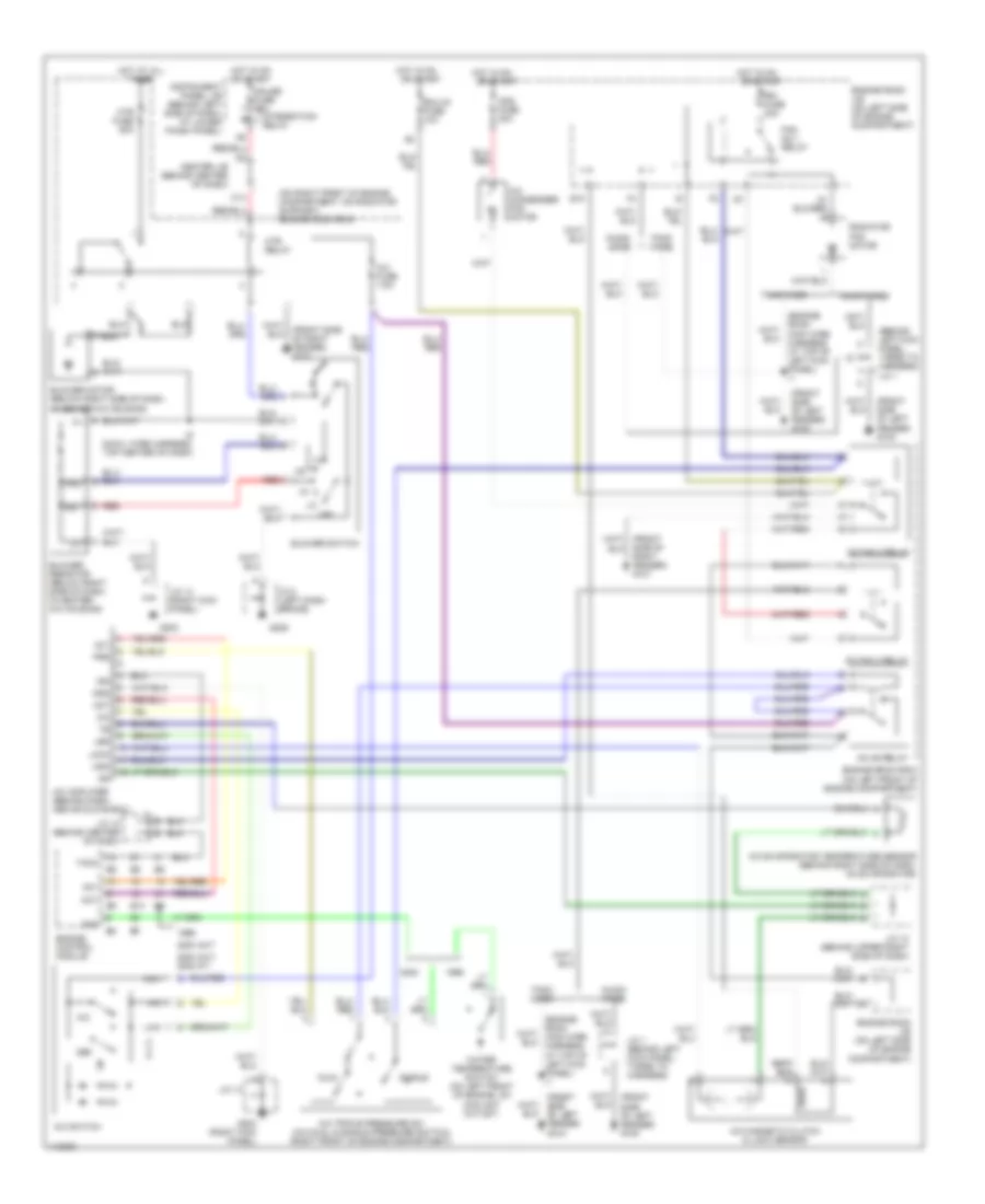
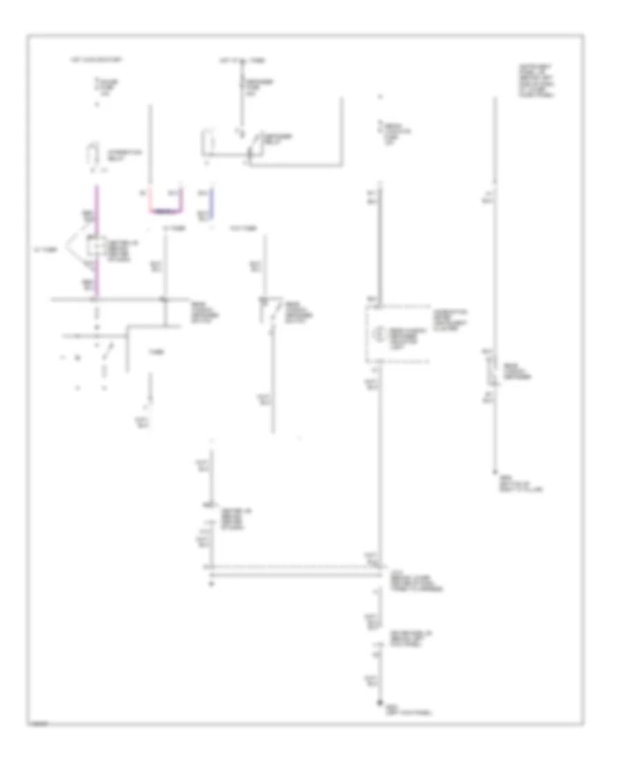
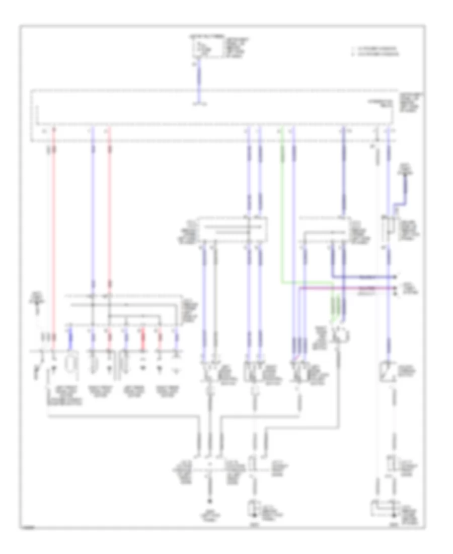
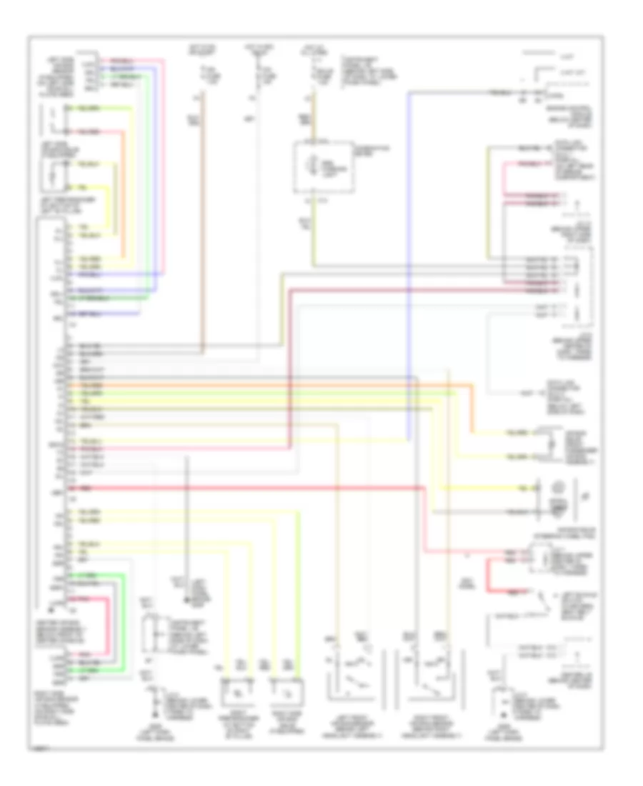
AIR CONDITIONING
Heater Wiring Diagram for Toyota Corolla LE 2000
 https://portal-diagnostov.com/license.html
Automotive Electricians Portal FZCO
Automotive Electricians Portal FZCO
https://portal-diagnostov.com/license.html
https://portal-diagnostov.com/license.html
Automotive Electricians Portal FZCO
Automotive Electricians Portal FZCO
List of elements for Heater Wiring Diagram for Toyota Corolla LE 2000:
- (cowl wire harness, top center of dash) i6
- (front side of right fender) g101
- Blower motor (below right side of dash, in heater-a/c housing)
- Blower resistor (below right side of dash, in heater-a/c housing)
- Blower switch
- C14
- Center j/b (behind center of dash)
- Engine room r/b 6 (on right front of engine compartment, on radiator support)
- G203 (right kick panel)
- G206 (left dash brace)
- Gauge fuse 10a
- Hot at all times
- Hot in on or start
- Htr fuse 50a
- Htr relay
- Instrument panel j/b (behind left side of dash, lower finish panel)
- Integration relay
- J/c 14
- J/c 8
- Me1
- Me2
- Off
- Red
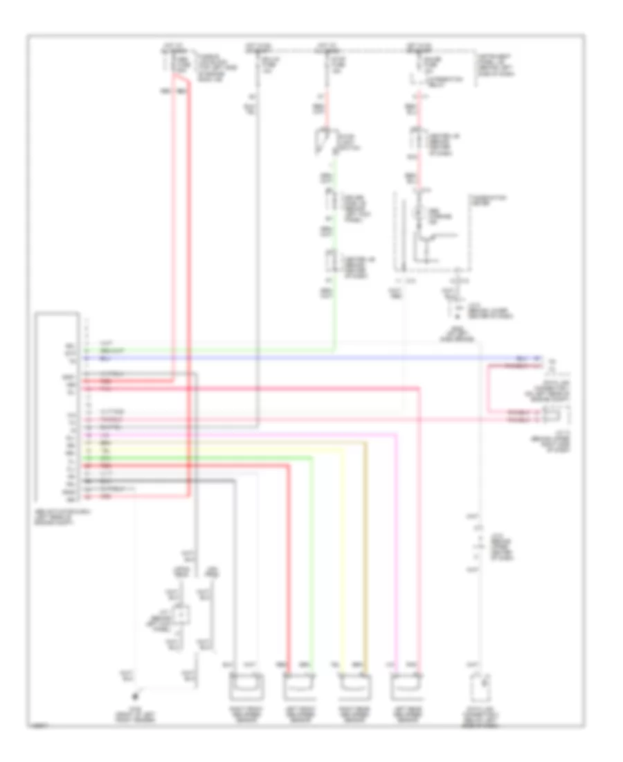
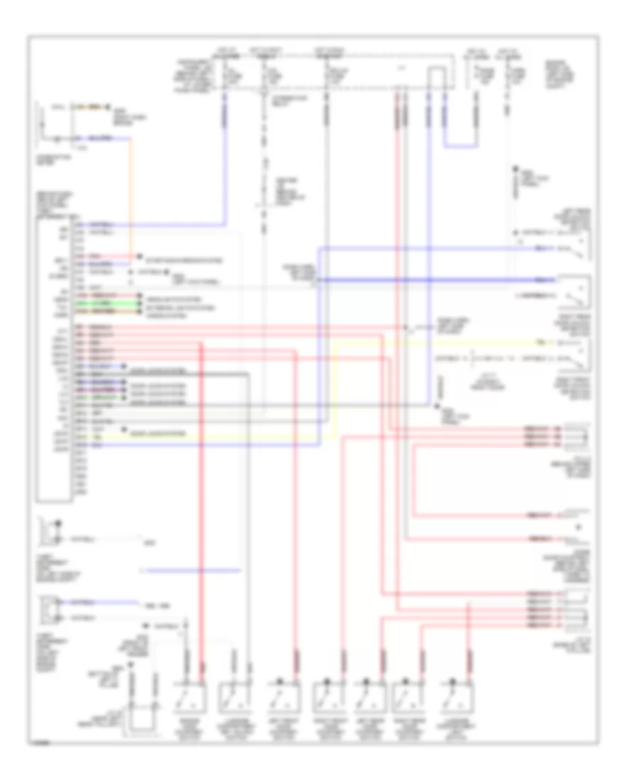
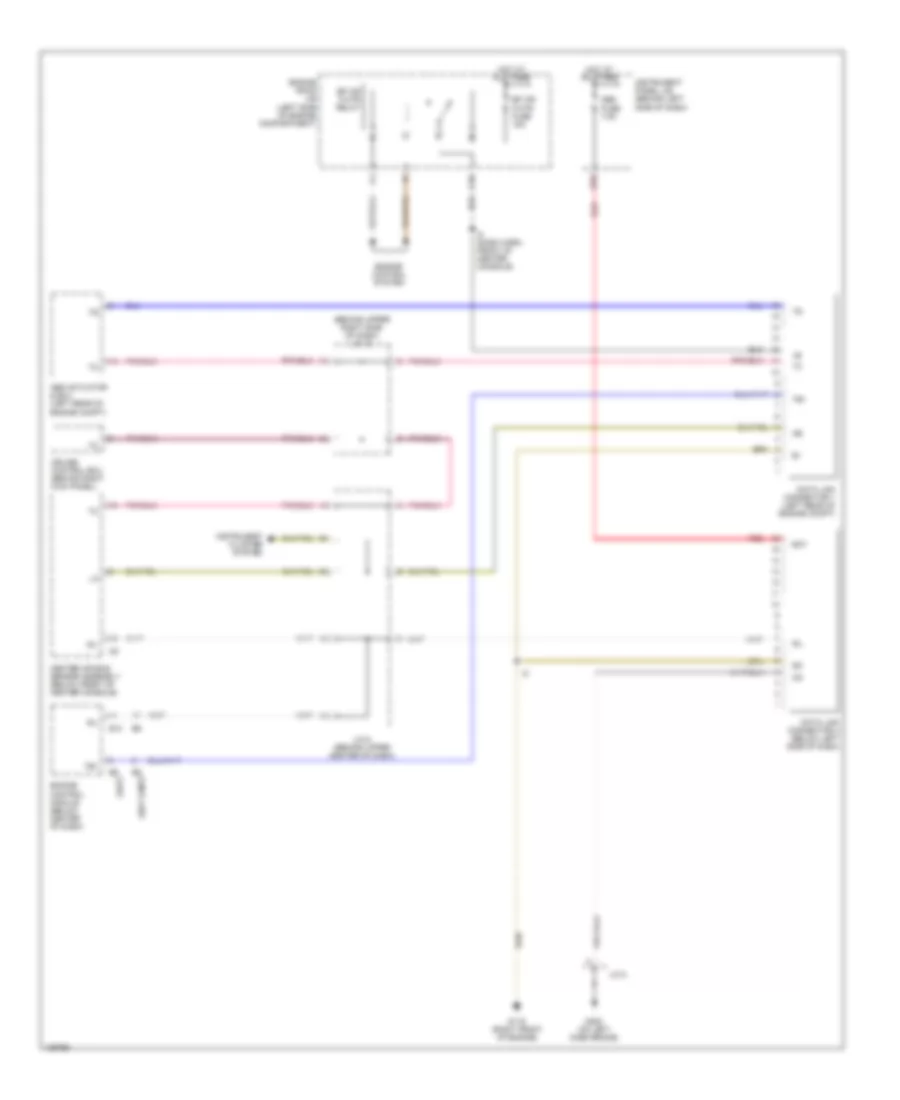
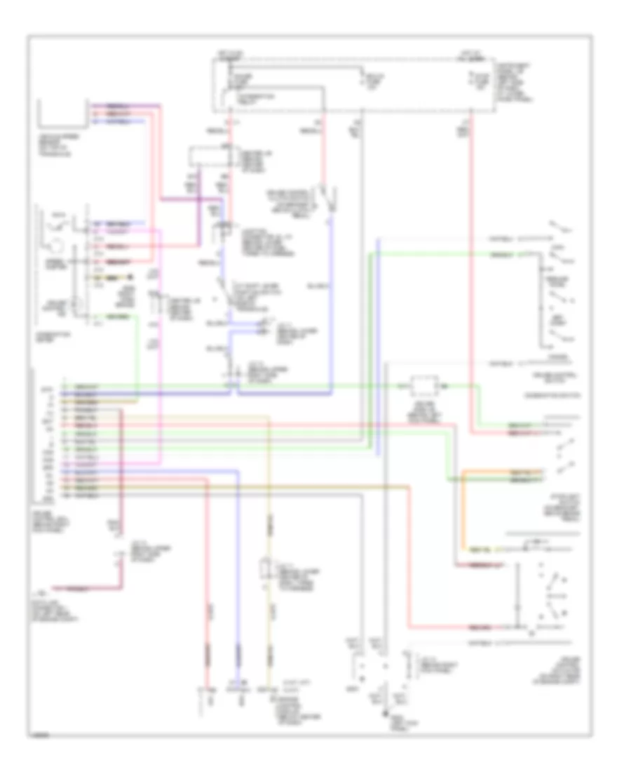
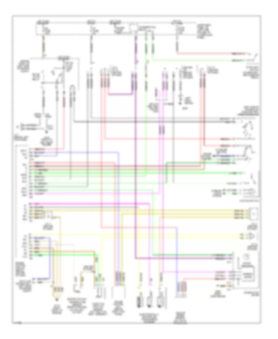
Manual A/C Wiring Diagram for Toyota Corolla LE 2000
List of elements for Manual A/C Wiring Diagram for Toyota Corolla LE 2000:
- (behind left kick panel, taped to harness) j/c 1
- (engine room main wire harness, at top of left kick panel) i1
- (front side of left fender) g100
- (on right front of engine compartment, on radiator support) engine room r/b 6
- 2000 3a/t, 2000 m/t
- 2000 4a/t
- A/c
- A/c amplifier (behind dash, above glove box)
- A/c condenser fan motor
- A/c evaporator temperature sensor (behind right side of dash, on evaporator)
- A/c fuse 7.5a
- A/c magnetic clutch & lock sensor
- A/c switch
- A/c triple pressure sw (a/c dual & single pressure switch) (right front of engine compartment)
- A/c+
- Ac fan 2 relay
- Ac fan 3 relay
- Ac mg relay
- Ac1
- Act
- Blower motor (below right side of dash, in heater-a/c housing)
- Blower resistor (below right side of dash, in heater- a/c housing)
- Blower switch
- C14
- Cds fuse 30a
- Center j/b (behind center of dash)
- Def
- Dual
- E10
- Ecu-ig fuse 10a
- Engine control module
- Engine room j/b (on left side of engine compartment)
- Engine room r/b 5 (on left front of engine compartment)
- Fan
- Fan no.1 relay
- G203
- G203 (right kick panel)
- G206
- Gauge fuse 10a
- Gnd
- Hot at all times
- Hot in on
- Hot in on or start
- Htr fuse 50a
- Htr relay
- I6 (cowl wire harness, top center of dash)
- Ign
- Instrument panel j/b (behind left side of dash, at lower finish panel)
- Integration relay
- J/c 1 (behind left kick panel, taped to harness)
- J/c 10 (behind center of dash)
- J/c 13 (behind upper right side of dash)
- J/c 14
- J/c 14 (right kick panel)
- J/c 8 (left dash brace)
- La/c
- Led
- Lock
- Me1
- Me2
- Mgc
- Nummi made
- Off
- Or start
- Prs
- Radiator fan motor
- Rdi fuse 30a
- Red
- Side of right fender) g101
- Single
- Tach
- Tmmc made
- Water temperature switch (on left front of engine, on coolant outlet)
ANTI-LOCK BRAKES
Anti-lock Brake Wiring Diagrams for Toyota Corolla LE 2000
List of elements for Anti-lock Brake Wiring Diagrams for Toyota Corolla LE 2000:
- +bm
- +bs
- Abs actuator & ecu (left rear of engine compt)
- Abs fuse 50a
- Abs warning ind
- B18
- C13
- C14
- Center j/b (behind center of dash)
- Combination meter
- Data link connector 1 (on left rear of engine compt)
- Data link connector 3 (below left side of dash)
- Driver side j/b (behind left kick panel)
- Ecu-ig fuse 10a
- Fl+
- Fl-
- Fr+
- Fr-
- Fusible link block (top left side of engine room j/b)
- G100 (front of left front fender)
- G205 (on left dash brace)
- Gauge fuse 10a
- Gnd1
- Gnd2
- Hot at all times
- Hot in on or start
- I11
- Instrument panel j/b (behind left side of dash)
- Integration relay
- J/c 1 (behind left kick panel)
- J/c 13 (behind upper right side of dash)
- J/c 6 (behind upper center of dash)
- J/c 8 (behind lower center of dash)
- Japan prod
- Left front abs speed sensor
- Left rear abs speed sensor
- Pnk
- Red
- Right front abs speed sensor
- Right rear abs speed sensor
- Rl+
- Rl-
- Rr+
- Rr-
- Sdl
- Sil
- Stop fuse 15a
- Stop- light switch
- Stp
- Usa prod
ANTI-THEFT
Anti-theft Wiring Diagram for Toyota Corolla LE 2000
List of elements for Anti-theft Wiring Diagram for Toyota Corolla LE 2000:
- (behind dash, above left kick panel) theft deterrent ecu
- (bottom of left c- pillar)
- (dash harn, left side of dash)
- (dash harn, left side of dash) i4
- +b1
- +b2
- 1998, 1999
- A10
- A11
- A12
- Acc
- B10
- B11
- B12
- B13
- B14
- B15
- B16
- B17
- B18
- B19
- B20
- B21
- B22
- C12
- C19
- Center j/b (behind center of dash)
- Cig fuse 15a
- Combination meter
- Cty
- D/l fuse 30a
- Diode (door courtesy) (behind left side of dash, taped to harness)
- Dome fuse 15a
- Door locks system
- Dswd
- Dswh
- Dswl
- Dswp
- E (grd)
- Ecu-ig fuse 10a
- Engine hood courtesy switch
- Engine room j/b (left side of engine compt)
- Exterior lights system
- F11
- G100 (front of left front fender)
- G200 (left kick panel)
- G206 (right dash brace)
- G904
- Head
- Headlights system
- Horn
- Horn fuse 10a
- Horns system
- Hot at all times
- Hot in accy or run
- Hot in run or start
- I11
- Ind
- Instrument panel j/b (behind left side of dash, at lower finish panel)
- Integration relay
- J/c 17 (in right front door)
- J/c 18 (base of left c-pillar)
- J/c 19 (near left rear taillight)
- J/c 4, 5 (behind upper left side of dash)
- Ksw
- Left front door courtesy switch
- Left rear door courtesy switch
- Left rear door unlock detection switch
- Lswd
- Lswp
- Lswr
- Lug
- Luggage compartment key unlock switch
- Luggage compartment light switch
- Pnk
- Red
- Right front door courtesy switch
- Right front door unlock detection switch
- Right rear door courtesy switch
- Right rear door unlock detection switch
- Sh-
- Srly
- Starting/charging system
- Tail
- Theft deterrent horn (on left side of engine compt)
- Ul2
- Ul3
COMPUTER DATA LINES
Computer Data Lines for Toyota Corolla LE 2000
List of elements for Computer Data Lines for Toyota Corolla LE 2000:
- (3a/t & m/t)
- (4a/t)
- (behind upper right side of dash) j/c 13
- Abs actuator & ecu (left rear of engine compt)
- Bat
- C10
- Center air bag sensor assembly (below front of center console)
- Cruise control ecu (behind right kick panel)
- Data link connector 1 (left rear of engine compt)
- Data link connector 3 (below left side of dash)
- E10
- Efi or f-htr fuse 15a
- Efi or f-htr relay
- Engine control module (below center of dash)
- Engine control system
- Engine room j/b (left side of engine compartment)
- G119 (right front of engine)
- G205 (on left dash brace)
- Hot at all times
- I8 (dash harn, front of center console)
- Instrument cluster system
- Instrument panel j/b (behind left side of dash)
- J/c 6 (behind upper center of dash)
- J/c 8
- Obd fuse 7.5a
- Red
- Sil
- Te1
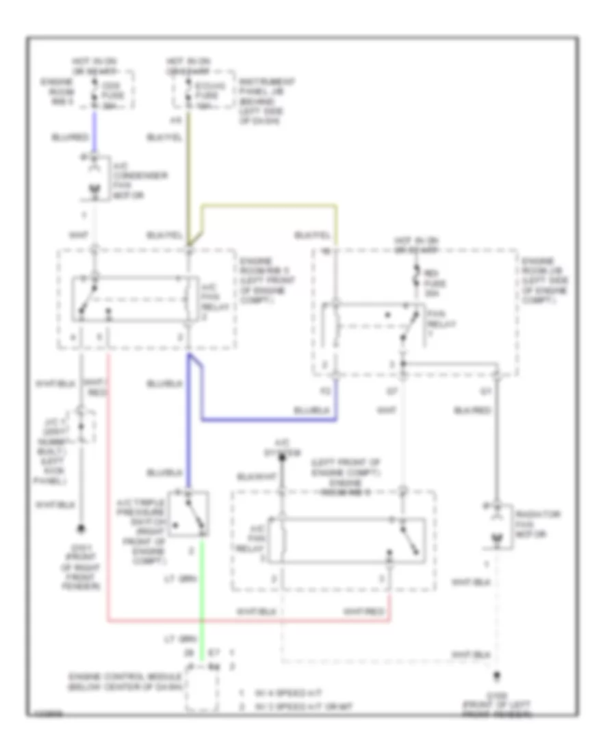
COOLING FAN
Cooling Fan Wiring Diagram for Toyota Corolla LE 2000
List of elements for Cooling Fan Wiring Diagram for Toyota Corolla LE 2000:
- (left front of engine compt) engine room r/b 5
- A/c condenser fan motor
- A/c fan relay
- A/c system
- A/c triple pressure switch (right front of engine compt)
- Cds fuse 30a
- Ecu-ig fuse 10a
- Engine control module (below center of dash)
- Engine room j/b (left side of engine compt)
- Engine room r/b 5
- Engine room r/b 5 (left front of engine compt)
- Fan relay
- G100 (front of left front fender)
- G101 (front of right front fender)
- Hot in on or start
- Instrument panel j/b (behind left side of dash)
- J/c 1 (2001 nummi built) (left kick panel)
- Radiator fan motor
- Rdi fuse 30a
- W/ 3 speed a/t or m/t
- W/ 4 speed a/t
CRUISE CONTROL
Cruise Control Wiring Diagram for Toyota Corolla LE 2000
List of elements for Cruise Control Wiring Diagram for Toyota Corolla LE 2000:
- (3 a/t, m/t)
- (4 a/t)
- A/t shift lever position switch (on left side of transaxle)
- A18
- B18
- B19
- C1 e6
- C11
- C12
- C13
- C14
- C7 e6
- Cancel
- Ccs
- Center j/b (behind center of dash)
- Cms
- Combination meter
- Combination switch
- Cruise control actuator (on right rear of engine compt)
- Cruise control clutch switch (on bracket above clutch pedal)
- Cruise control ecu (behind right kick panel)
- Cruise control ind
- Cruise control switch
- D20 e7
- D4 d4 d4
- Data link connector 1 (on left rear of engine compt)
- Driver side j/b (behind left kick panel)
- Ect
- Ecu-ig fuse 10a
- Engine control module (below center of dash)
- G10 e10
- G203
- G206 (right dash brace)
- G20o (left kick panel)
- Gauge fuse 10a
- Gnd
- Hot at all times
- Hot in on & start
- I11
- Idl
- Idlo
- Instrument panel j/b (behind left side of dash, at lower finish panel)
- Integration relay
- J/c 11 (behind lower center of dash)
- J/c 11 (behind lower center of dash, taped to harness)
- J/c 13 (behind upper right side of dash)
- J/c 14 (behind right kick panel)
- Junction connector j9, j10 (behind lower center of dash, taped to harness)
- Main
- Od1
- Resume/ accel
- Set/ coast
- Spd
- Speed- ometer
- Stop fuse 15a
- Stoplight switch (on bracket, above brake pedal)
- Stp-
- Vehicle speed sensor (on top of transaxle)
DEFOGGERS
Defogger Wiring Diagram for Toyota Corolla LE 2000
List of elements for Defogger Wiring Diagram for Toyota Corolla LE 2000:
- (bottom of right "c" pillar)
- C13
- C15
- Center j/b (behind center of dash)
- Combination meter (instrument cluster)
- Defog- i-up/m-htr fuse 10a
- Defogger fuse 40a
- Defogger relay
- Driver side j/b (behind left kick panel)
- E11
- E12
- E13
- G200 (left kick panel)
- G905
- Gauge fuse 10a
- Hot at all times
- Hot in on or start
- I11
- Instrument panel j/b (behind left side of dash, at lower finish panel)
- Integration relay
- J/c 8 (behind lower center of dash, taped to harness)
- Rear window defogger
- Rear window defogger indicator light
- Rear window defogger switch
- Timer
- W/ timer
- W/o timer
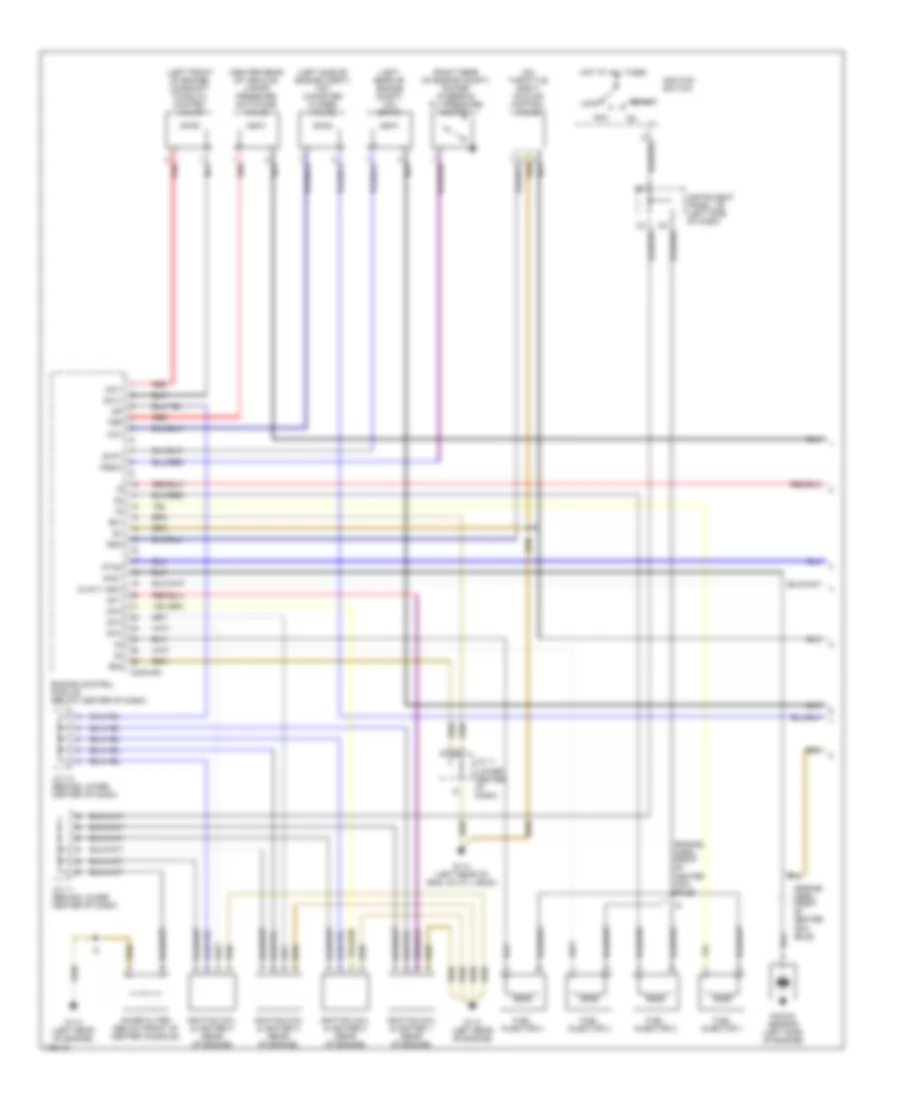
ENGINE PERFORMANCE
1.8L
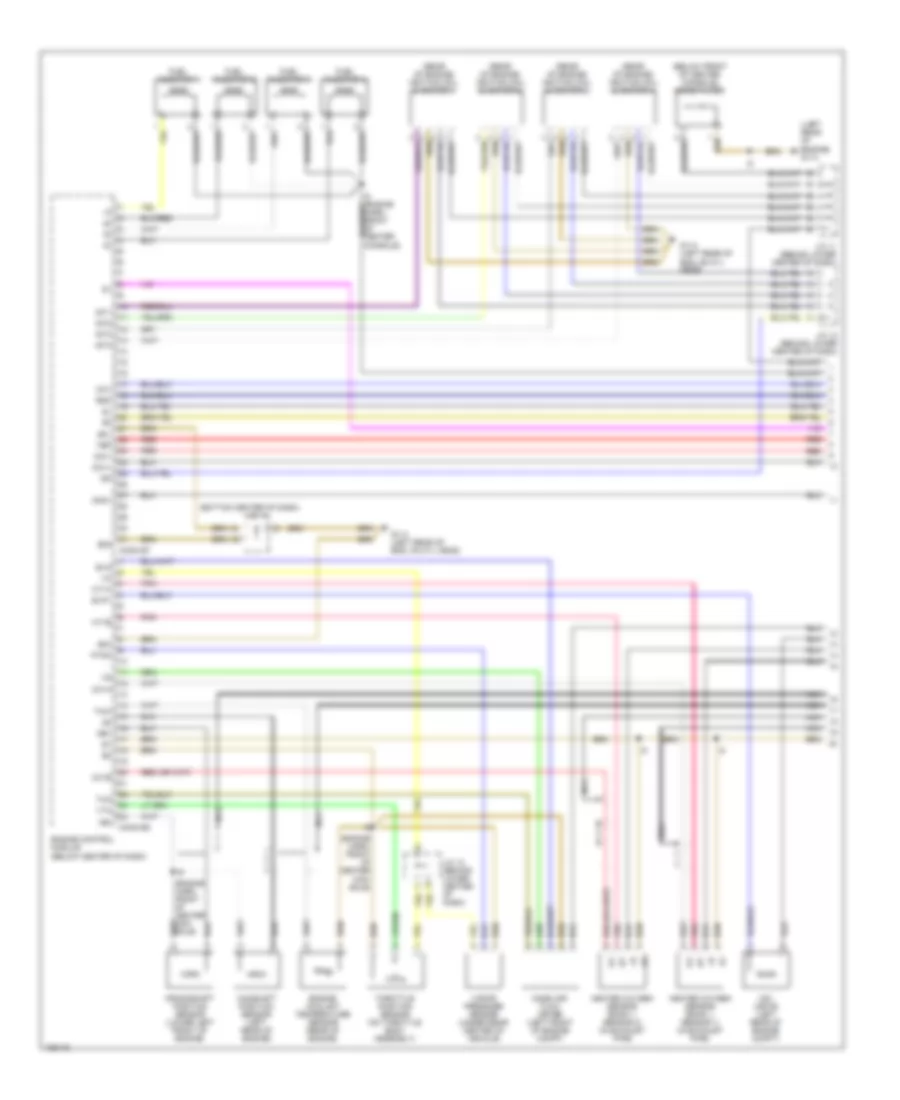
1.8L, Engine Performance Wiring Diagrams, 3 Speed A/T & M/T (1 of 3) for Toyota Corolla LE 2000
List of elements for 1.8L, Engine Performance Wiring Diagrams, 3 Speed A/T & M/T (1 of 3) for Toyota Corolla LE 2000:
- (center rear of vehicle) vapor pressure switching valve
- (engine harn, front of center con- sole)
- (left front of engine) camshaft timing oil control valve
- (left rear of engine compt) vsv (orvr)
- (left side of engine compt) vsv (canister closed valve)
- (lower center of dash)
- (on throttle body) idle air control valve
- (right rear of engine compt) power steering oil pressure switch
- (w/a/t)
- Acc
- Ccv
- Conn e4
- E01
- E02
- Engine control module (below center of dash)
- Evp1
- Fuel injector 1
- Fuel injector 2
- Fuel injector 3
- Fuel injector 4
- G114 (left rear of eng, on cyl head)
- G114 (left rear of engine)
- Hot at all times
- Igf
- Ignition coil & igniter 1 (rear of engine)
- Ignition coil & igniter 2 (rear of engine)
- Ignition coil & igniter 3 (rear of engine)
- Ignition coil & igniter 4 (rear of engine)
- Ignition switch
- Igt1
- Igt2
- Igt3
- Igt4
- Instrument panel j/b (left side of dash)
- J/c 11
- J/c 11 (behind lower center of dash)
- J/c 12 (behind lower center of dash)
- Knk1
- Knock sensor (left side of engine)
- Lock
- Noise filter (below front of center console)
- Nsw
- Ocv+
- Ocv-
- Pssw
- Ptnk
- Red
- Rso
- Start
- Tbp
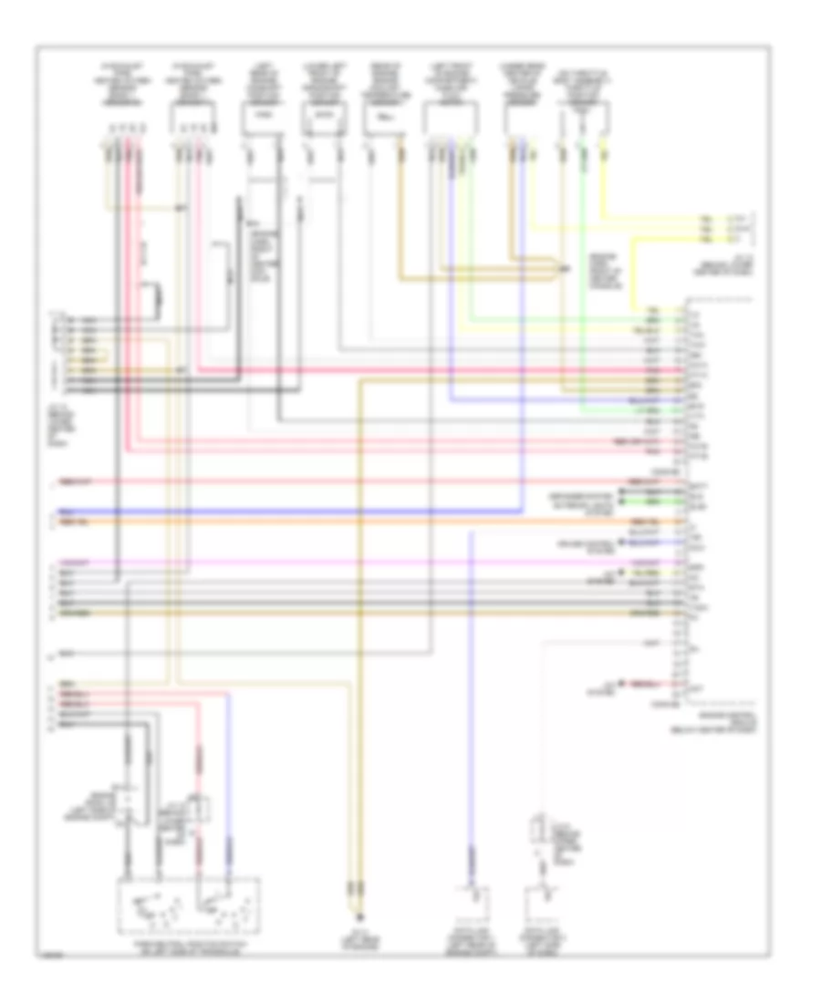
1.8L, Engine Performance Wiring Diagrams, 3 Speed A/T & M/T (2 of 3) for Toyota Corolla LE 2000
List of elements for 1.8L, Engine Performance Wiring Diagrams, 3 Speed A/T & M/T (2 of 3) for Toyota Corolla LE 2000:
- (w/a/t)
- (w/m/t)
- C10
- C12
- C13
- C14
- Center j/b (behind center of dash)
- Circuit opening relay
- Clutch start switch (above clutch pedal)
- Driver side j/b (behind left kick panel)
- Driver side r/b (behind left kick panel)
- Efi or f-htr fuse 15a
- Efi or f-htr relay
- Engine room j/b (left side of engine compt)
- Fuel pump
- G100 (front of left front fender)
- G904 (bottom of left "c" pillar trim)
- Gauge fuse 10a
- Hot at all times
- Hot in on or start
- Hot in start
- I11
- I8 (engine harn, front of center console)
- Ign fuse 7.5a
- Instrument cluster
- Instrument panel j/b (left side of dash)
- Integration relay (on rear of instrument panel j/b)
- J/c 1 (nummi made) (behind left kick panel)
- J/c 9,10 (behind lower center of dash)
- Malfunction indicator lamp
- Speedometer
- St fuse 5a
- Tachometer
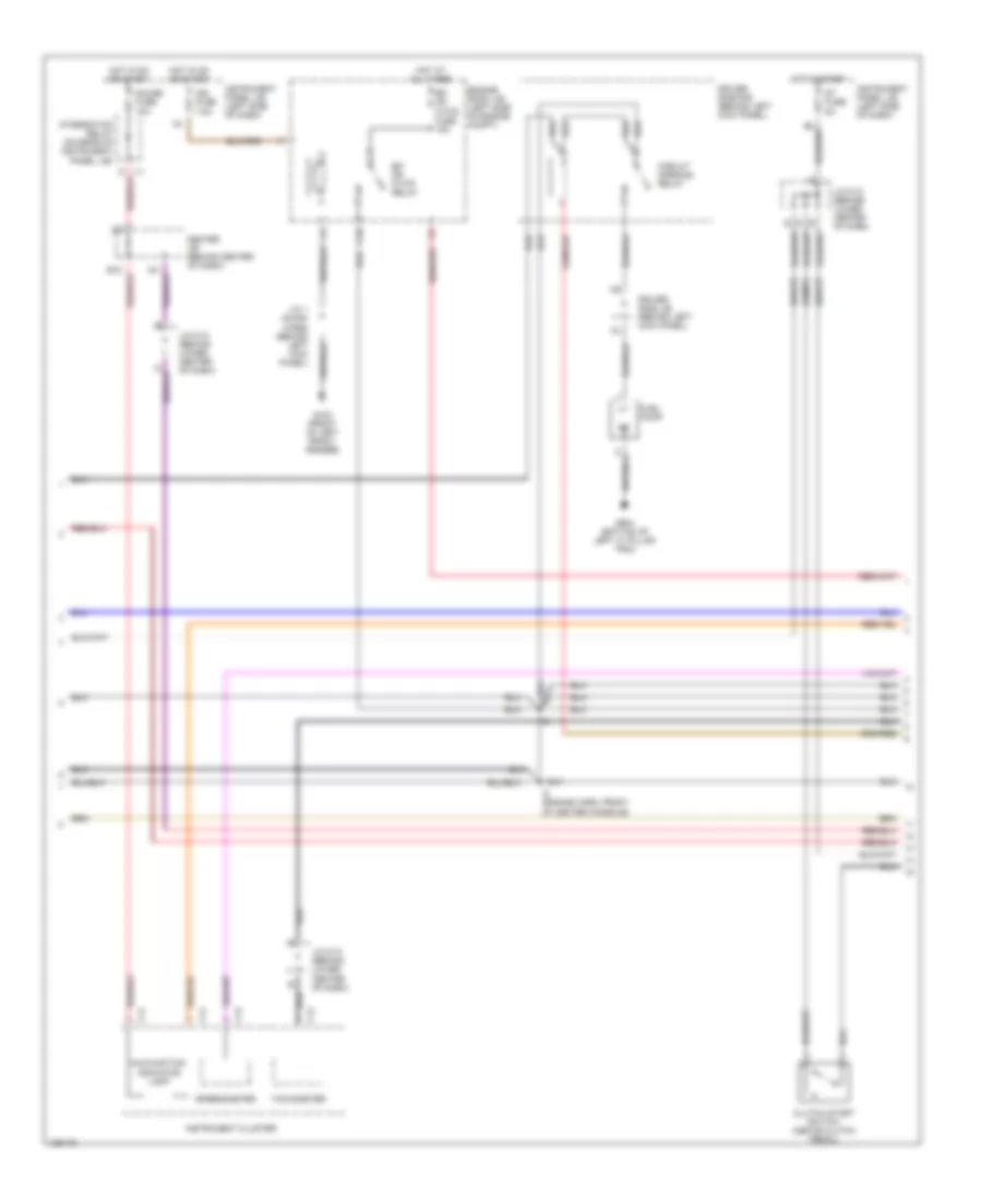
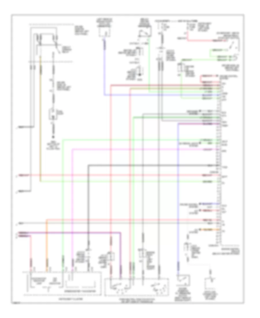
1.8L, Engine Performance Wiring Diagrams, 3 Speed A/T & M/T (3 of 3) for Toyota Corolla LE 2000
List of elements for 1.8L, Engine Performance Wiring Diagrams, 3 Speed A/T & M/T (3 of 3) for Toyota Corolla LE 2000:
- (engine harn, front of center con- sole)
- (engine harn, front of center console)
- (in exhaust pipe) heated oxygen sensor (bank 1, sensor 1)
- (in exhaust pipe) heated oxygen sensor (bank 1, sensor 2)
- (left front of engine compartment) mass air- flow meter
- (left rear of engine) camshaft position sensor
- (lower left front of engine) crankshaft position sensor
- (on throttle body assembly) throttle position sensor
- (rear of engine) engine coolant temperature sensor
- (under rear center of vehicle) vapor pressure sensor
- A/c system
- Act
- Batt
- Conn e5
- Conn e6
- Cruise control system
- Data link connector 1 (left rear of engine compt)
- Data link connector 3 (left side of dash)
- Defogger system
- E03
- E11
- Els
- Els2
- Engine control module (below center of dash)
- Engine room j/b (left side of engine compt)
- Evg
- Exterior lights system
- G114 (left rear of engine)
- Ht1a
- Ht1b
- Idlo
- J/c 12 (behind lower center of dash)
- J/c 6 (behind upper center of dash)
- Nca
- Ne+
- Ne-
- Ox1a
- Ox1b
- Park/neutral position switch (on left side of transaxle)
- Pnk
- Sil
- Spd
- Sta
- Tach
- Te1
- Tha
- Thw
- Vta
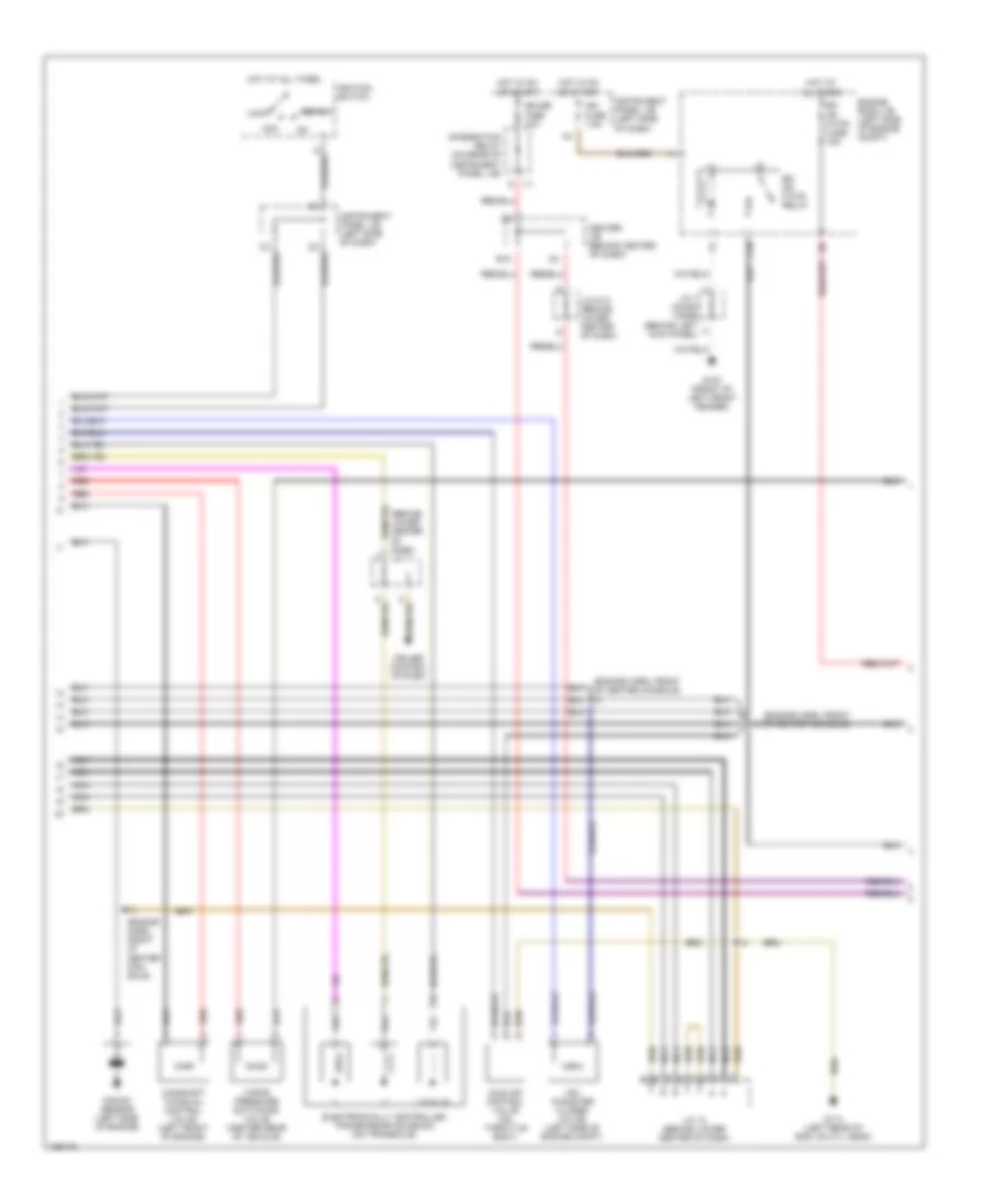
1.8L, Engine Performance Wiring Diagrams, 4 Speed A/T (1 of 3) for Toyota Corolla LE 2000
List of elements for 1.8L, Engine Performance Wiring Diagrams, 4 Speed A/T (1 of 3) for Toyota Corolla LE 2000:
- (below front of center console) noise filter
- (bottom center of dash)
- (engine harn, front of center con- sole)
- (left rear of engine) g114
- (rear of engine) ignition coil & igniter 1
- (rear of engine) ignition coil & igniter 2
- (rear of engine) ignition coil & igniter 3
- (rear of engine) ignition coil & igniter 4
- Camshaft position sensor (left rear of engine)
- Ccv
- Conn e7
- Conn e8
- Crankshaft position sensor (lower left front of engine)
- E01
- E02
- E03
- Engine control module (below center of dash)
- Engine coolant temperature sensor (rear of engine)
- Evg
- Evp1
- Fuel injector 1
- Fuel injector 2
- Fuel injector 3
- Fuel injector 4
- G114 (left rear of eng, on cyl head)
- Heated oxygen sensor (bank 1, sensor 1) (in exhaust pipe)
- Heated oxygen sensor (bank 1, sensor 2) (in exhaust pipe)
- Ht1a
- Ht1b
- Igf
- Igt1
- Igt2
- Igt3
- Igt4
- J/c 11
- J/c 11 (behind lower center of dash)
- J/c 12 (behind lower center of dash)
- Knk1
- Mass air- flow meter (left front of engine compt)
- Nca
- Ne+
- Ne-
- Ocv+
- Ocv-
- Ox1a
- Ox1b
- Pnk
- Ptnk
- Red
- Rso
- Tbp
- Tha
- Throttle position sensor (on throttle body assembly)
- Thw
- Vapor pressure sensor (under rear center of vehicle)
- Vsv (orvr) (left rear of engine compt)
- Vta
1.8L, Engine Performance Wiring Diagrams, 4 Speed A/T (2 of 3) for Toyota Corolla LE 2000
List of elements for 1.8L, Engine Performance Wiring Diagrams, 4 Speed A/T (2 of 3) for Toyota Corolla LE 2000:
- (behind lower center of dash) j/c 11
- (engine harn, front of center con- sole)
- (engine harn, front of center console)
- (engine harn, front of center console) i8
- Acc
- B18
- C10
- Camshaft timing oil control valve (left front of engine)
- Center j/b (behind center of dash)
- Cruise control system
- Efi or f-htr fuse 15a
- Efi or f-htr relay
- Electronically controlled transmission solenoid (on transaxle)
- Engine room j/b (left side of engine compt)
- G100 (front of left front fender)
- G114 (left rear of eng, on cyl head)
- Gauge fuse 10a
- Hot at all times
- Hot in on or start
- I11
- Idle air control valve (on throttle body)
- Ign fuse 7.5a
- Ignition switch
- Instrument panel j/b (left side of dash)
- Integration relay (on rear of instrument panel j/b)
- J/c 1 (nummi made) (behind left kick panel)
- J/c 12 (behind lower center of dash)
- J/c 9,10 (behind lower center of dash)
- Knock sensor (left side of engine)
- Lock
- Lock-up
- Nca
- Red
- Start
- Vapor pressure switching valve (center rear of vehicle)
- Vsv (canister closed valve) (left side of engine compt)
1.8L, Engine Performance Wiring Diagrams, 4 Speed A/T (3 of 3) for Toyota Corolla LE 2000
List of elements for 1.8L, Engine Performance Wiring Diagrams, 4 Speed A/T (3 of 3) for Toyota Corolla LE 2000:
- (below center console) o/d switch
- (left rear of engine compt) data link connector 1
- (on bracket, above brake pedal) stoplight switch
- A/c system
- Act
- Batt
- C12
- C13
- C14
- Center j/b (behind center of dash)
- Circuit opening relay
- Conn e10
- Conn e9
- Cruise control system
- Data link connector 3 (left side of dash)
- Defogger system
- Driver side j/b (behind left kick panel)
- Driver side r/b (behind left kick panel)
- E11
- Els
- Els2
- Engine control module (below center of dash)
- Engine room j/b (left side of engine compt)
- Exterior lights system
- Fuel pump
- G302
- G904 (bottom of left "c" pillar trim)
- Hot at all times
- Hot in start
- Idlo
- Instrument cluster
- Instrument panel j/b (left side of dash)
- J/c 12 (behind lower center of dash)
- J/c 6 (behind upper center of dash)
- J/c 8 (behind lower center of dash)
- J/c 9,10 (behind lower center of dash)
- Malfunction indicator lamp
- Nsw
- O/d off indicator
- Od1
- Odlp
- Odms
- Park/neutral position switch (on left side of transaxle)
- Power steering oil pressure switch (right rear of engine compt)
- Pssw
- Sil
- Spd
- Speedometer
- St fuse 5a
- Sta
- Stop fuse 15a
- Stp
- Tach
- Tachometer
- Te1
EXTERIOR LIGHTS
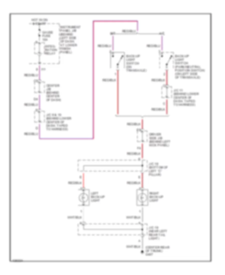
Back-up Lamps Wiring Diagram for Toyota Corolla LE 2000
List of elements for Back-up Lamps Wiring Diagram for Toyota Corolla LE 2000:
- (center rear of trunk) g407
- A/t
- Back-up light switch (on transaxle)
- Back-up light switch (park/neutral position switch) (on left side of transaxle)
- Center j/b (behind center of dash)
- Driver side j/b (behind left kick panel)
- Gauge fuse 10a
- Hot in on & start
- I11
- Instrument panel j/b (behind left side of dash, at lower finish panel)
- Integ- ration relay
- J/c 11 (behind lower center of dash, taped to harness)
- J/c 18 (bottom of left "c" pillar)
- J/c 19 (near left rear tail light)
- J/c 9 & 10 (behind lower center of dash, taped to harness)
- Left back-up light
- M/t
- Right back-up light
Exterior Lamps Wiring Diagram for Toyota Corolla LE 2000
List of elements for Exterior Lamps Wiring Diagram for Toyota Corolla LE 2000:
- Alt fuse 100a
- B10
- B12
- Combination switch
- Daytime running light relay (main) (behind dash, above glove box)
- Driver side j/b (left kick panel)
- Driver side r/b (left kick panel)
- E13
- Engine room j/b (left side of engine compt)
- Fusible link box (top left side of engine room j/b)
- G100 (front of left front fender)
- G101 (front of right front fender)
- G200 (left kick panel)
- G203 (right kick panel)
- G205 (on left dash brace)
- G407 (center rear of trunk)
- G904 (bottom of left "c" pillar)
- Haz- fuse 10a
- Hazard switch
- Head
- High mounted stop- light
- Hot at all times
- Hot in on or start
- I3 i3 i3 i3 i3 i3
- Instrument panel j/b (behind left side of dash, at lower finish panel)
- J/c 1 (behind left kick panel, taped to harness)
- J/c 14 (right kick panel, taped to harness)
- J/c 18 (bottom of left "c" pillar)
- J/c 19 (near left rear taillight)
- J/c 8 (lower center of dash, taped to harness)
- Japan prod
- Left front park/ turn light
- Left rear combin- ation light
- License plate light
- Light control switch
- Meter combination
- Off
- Right front park/ turn light
- Right rear combin- ation light
- Stop
- Stop fuse 15a
- Stop- light switch (on bracket, above brake pedal)
- Tail
- Tail fuse 15a
- Taillight relay
- Turn
- Turn fuse 7.5a
- Turn signal indicator lights
- Turn signal switch
- Turn turn turn turn signal signal signal signal flasher flasher flasher flasher
- Usa prod
- W/ daytime running lights
- W/o daytime running lights
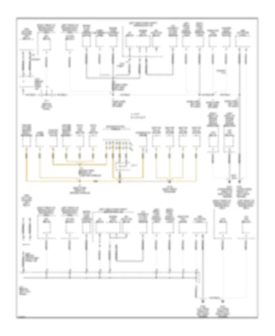
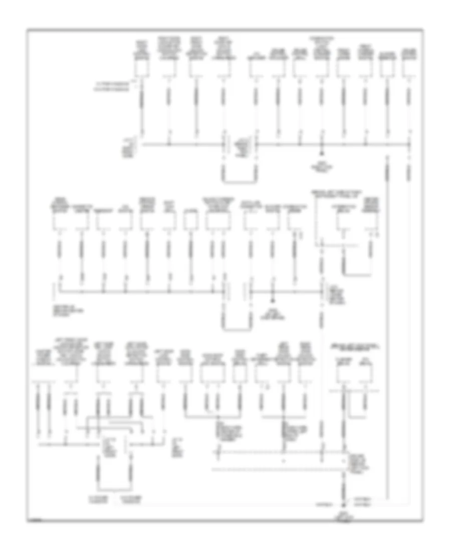
GROUND DISTRIBUTION
Ground Distribution Wiring Diagram (1 of 3) for Toyota Corolla LE 2000
List of elements for Ground Distribution Wiring Diagram (1 of 3) for Toyota Corolla LE 2000:
- (behind left kick panel)
- (left front of engine compt) engine room r/b 5
- (left side of eng compt) engine room j/b
- (right front of engine compt) engine room r/b 6
- (right front of engine compt) engine room r/b 6
- A 4 a/t
- A/c fan relay 2
- A/c fan relay 3
- A/c magnetic clutch & lock sensor
- Abs actuator & ecu
- B 3 a/t & m/t
- Brake fluid level warning switch
- C11
- Canada
- Combination meter
- Data link con- nector
- Drl relay
- E10
- Efi (or f-htr) relay
- Engine control module
- Engine hood courtesy switch
- Engine main relay
- G100 (japan prod) (front of left front fender)
- G100 (u.s. prod) (front of left front fender)
- G101 (japan prod) (front of right front fender)
- G101 (u.s. prod) (front of right front fender)
- G119 (right front of engine)
- Heated oxygen sensor (bank 1 sensor 1)
- Heated oxygen sensor (bank 1 sensor 2)
- Htr relay
- I1 (dash harn, left end of dash)
- I8 (dash harn, front of center console)
- Idle air control valve
- Ignition coil & igniter
- J/b 2 (behind instrumnet panel j/b)
- J/c 1
- J/c 1 (behind left kick panel)
- J/c 11
- J/c 2 (behind instr panel j/b)
- Left front turn signal/ parking light
- Main daytime running light relay
- Noise filter
- Radiator fan motor
- Right front turn signal/ parking light
- St relay
- Theft deterrent horn
- U.s.
- W/o theft
- Washer level warning switch
Ground Distribution Wiring Diagram (2 of 3) for Toyota Corolla LE 2000
List of elements for Ground Distribution Wiring Diagram (2 of 3) for Toyota Corolla LE 2000:
- (behind left kick panel) driver side r/b
- (behind left side of dash) instrument panel j/b
- A/c amplifier
- A19
- A20
- B1 (body harn, center of windshield header)
- B13
- B20
- Blower resistor
- Blower switch
- C13
- Center air bag sensor assembly
- Center j/b (behind center of dash)
- Cigarette lighter
- Clock
- Combination meter
- Combination switch (light control & dimmer switch)
- Cruise control actuator
- Cruise control ecu
- Cruise control switch
- D10
- Data link connector
- Driver side j/b (behind left kick panel)
- E13
- Flasher relay
- Front wiper & washer switch
- Front wiper motor
- G200 (left kick panel)
- G203 (right kick panel)
- G205 (on left dash brace)
- I2 (dash harn, upper left end of dash)
- Integration relay
- J/c 14 (behind right kick panel)
- J/c 15 (in left front door)
- J/c 16 (in left front door)
- J/c 17 (in right front door)
- J/c 8 (behind lower center of dash)
- Left door key lock lock & unlock switch (japan prod)
- Left door lock control switch
- Left door lock motor & unlock detection switch (japan prod)
- Left front door lock motor/ unlock detection switch/ door key lock & unlock switch (u.s. prod)
- Left rear door unlock detection switch
- Master power window switch
- Moon roof control relay
- Moon roof control switch
- Moon roof motor & limit switch
- O/d switch
- P/w relay
- Rear window defogger switch
- Remote control mirror switch
- Rheostat
- Right door key lock & unlock switch (japan prod)
- Right door lock control switch
- Right door lock motor & door key lock/unlock switch (u.s. prod)
- Right front door unlock detection switch
- Right rear door unlock detection switch
- Shift lock ecu
- Theft deterrent ecu
- Unlock warning switch & key interlock solenoid
- W/ power windows
- W/ pwr windows
- W/o power windows
- W/o pwr windows
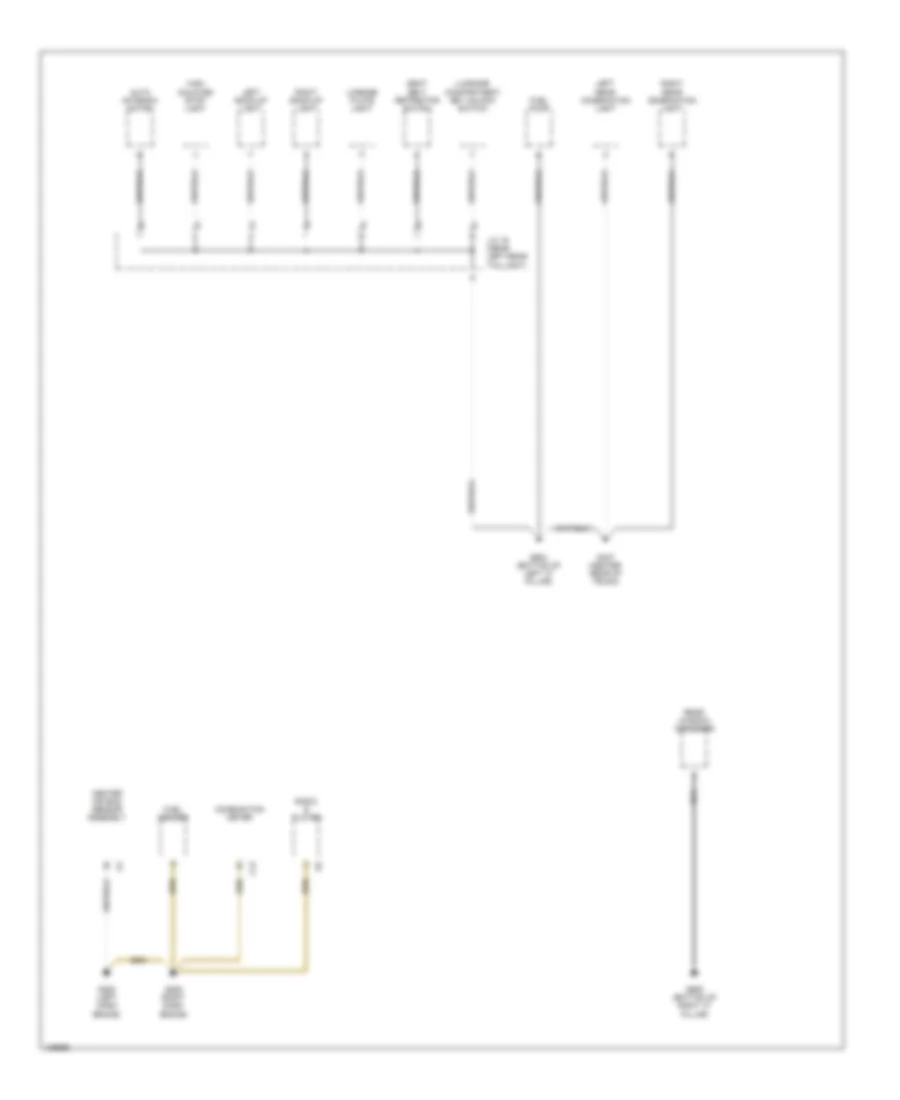
Ground Distribution Wiring Diagram (3 of 3) for Toyota Corolla LE 2000
List of elements for Ground Distribution Wiring Diagram (3 of 3) for Toyota Corolla LE 2000:
- Auto antenna motor
- C12
- Center air bag sensor assembly
- Combination meter
- Fuel pump
- Fuel sender
- G205 (left dash brace)
- G206 (right dash brace)
- G407 (center rear of trunk)
- G904 (bottom of left "c" pillar)
- G905 (bottom of right "c" pillar)
- High mounted stop light
- J/c 19 (near left rear taillight)
- Left back-up light
- Left rear combination light
- License plate light
- Luggage compartment key unlock switch
- Radio & player
- Rear window defogger
- Right back-up light
- Right rear combination light
- Seat belt retractor switch
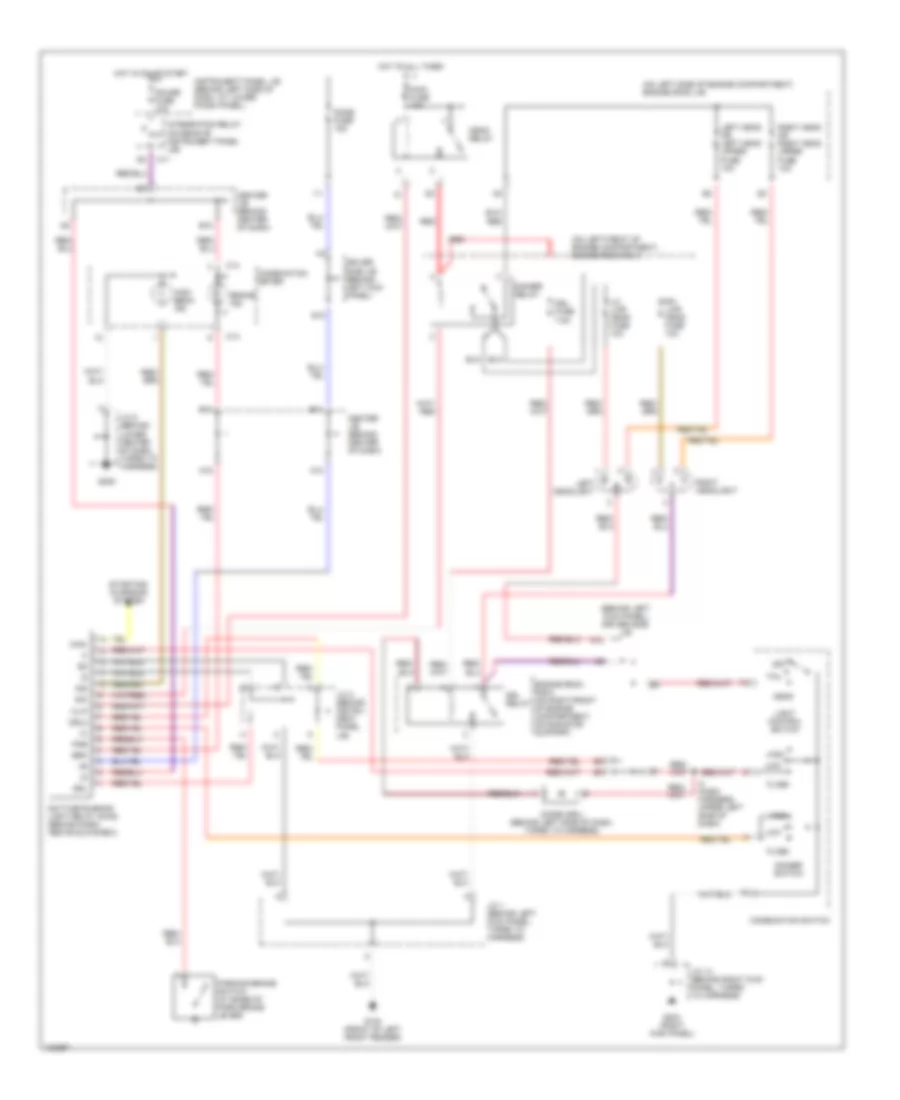
HEADLIGHTS
Headlight Wiring Diagram, Canada for Toyota Corolla LE 2000
List of elements for Headlight Wiring Diagram, Canada for Toyota Corolla LE 2000:
- (behind left kick panel) driver side j/b
- (on left front of engine compartment) engine room r/b 5
- (on left side of engine compartment) engine room j/b
- A10
- A16
- B11
- B17
- B18
- Brake ind
- Brk
- C11
- C13
- C14
- Center j/b (behind center of dash)
- Chg-
- Combination meter
- Combination switch
- Daytime running light relay (main) (behind dash, above glove box)
- Dim
- Dimmer relay
- Dimmer switch
- Diode (drl) (behind left side of dash, taped to harness)
- Dome fuse 15a
- Driver side j/b (behind left kick panel)
- Drl
- Drl fuse 7.5a
- Drl relay
- Drl2
- E10
- Engine room r/b 6 (on right front of engine compartment, on radiator support)
- Flash
- G100 (front of left front fender)
- G203 (right kick panel)
- G205
- Gauge fuse 10a
- H-lp
- Head
- Head relay
- High
- High beam ind
- Hot at all times
- Hot in on or start
- I11
- I4 (dash harness, upper left side of dash)
- Ind
- Instrument panel j/b (behind left side of dash, at lower finish panel)
- Integration relay (on rear of instrument panel j/b)
- J/c 1 (behind left kick panel, taped to harness)
- J/c 14 (behind right kick panel, taped to harness)
- J/c 2 (behind instru- ment panel j/b)
- J/c 8 (behind lower center of dash, taped to harness)
- Left head or left head upper fuse 10a
- Left headlight
- Lh- lwr head fuse 10a
- Light control switch
- Low
- Main fuse 40a
- Off
- Parking brake switch (at base of park brake lever)
- Pkb
- Red
- Rh- lwr head fuse 10a
- Right head or right head upper fuse 10a
- Right headlight
- Starting/ charging system
- Tail
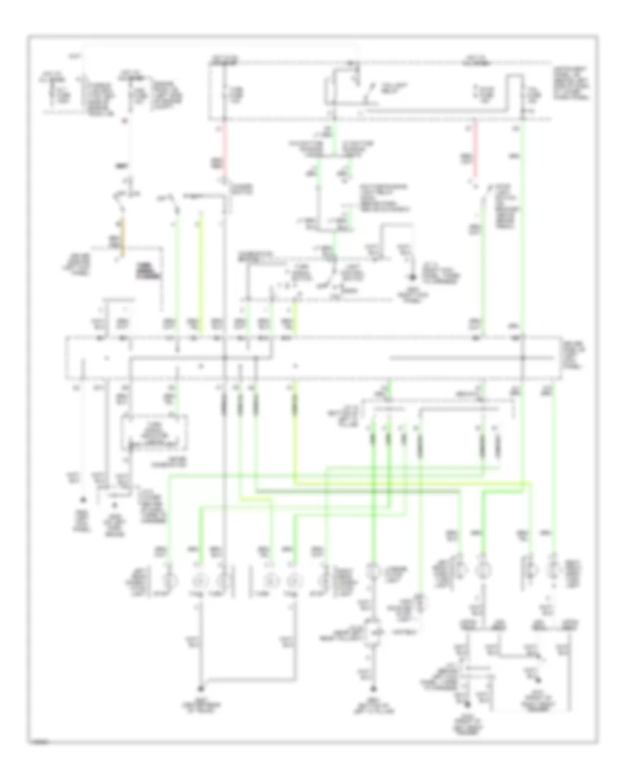
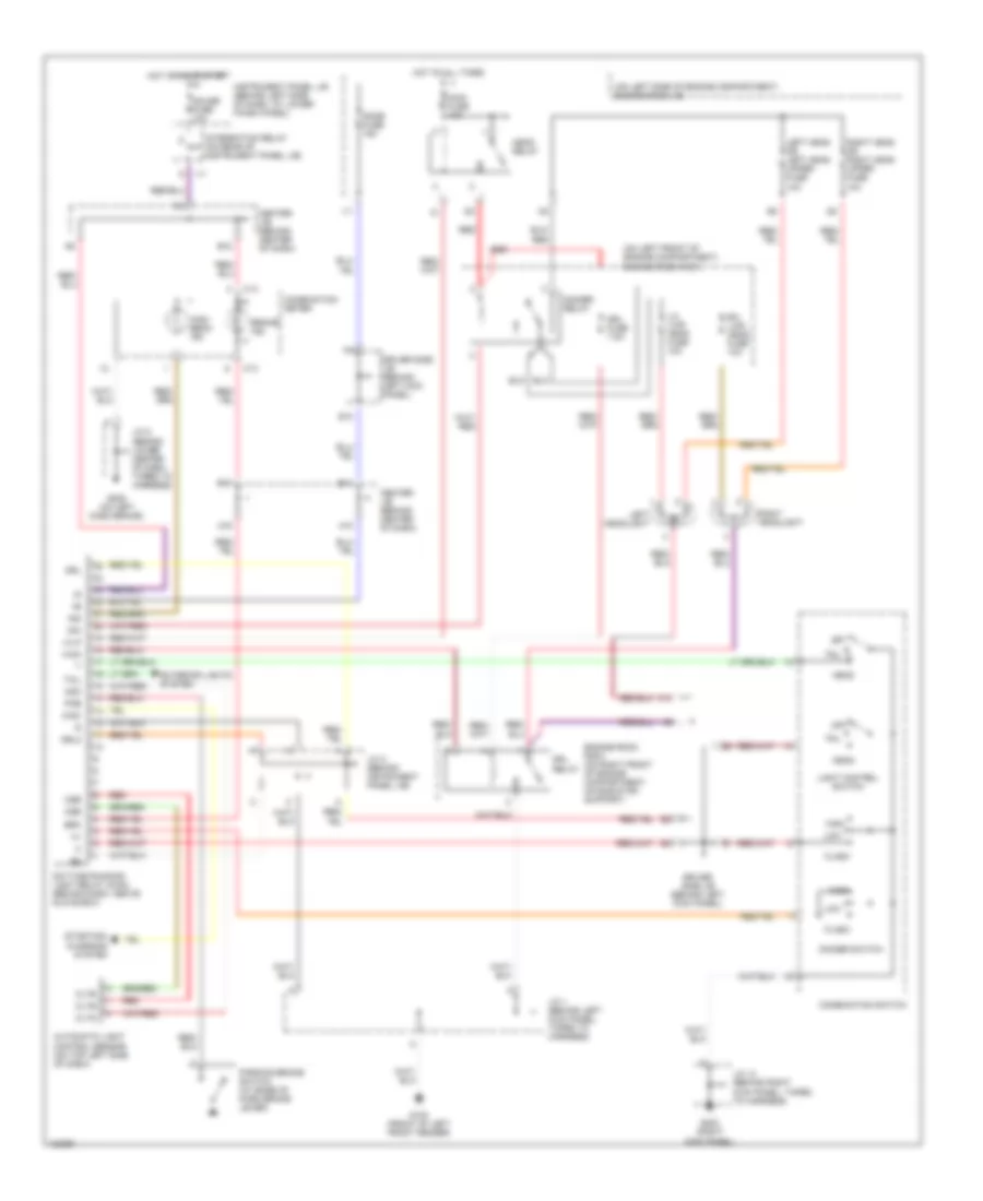
Headlight Wiring Diagram, USA for Toyota Corolla LE 2000
List of elements for Headlight Wiring Diagram, USA for Toyota Corolla LE 2000:
- (on left front of engine compartment) engine room r/b 5
- (on left side of engine compartment) engine room j/b
- A10
- A16
- Automatic light control sensor (on top left side of dash)
- B11
- B17
- B18
- Brake ind
- Brk
- C13
- C14
- Center j/b (behind center of dash)
- Chg-
- Cltb
- Clte
- Clts
- Combination meter
- Combination switch
- Csb
- Cse
- Cso
- Daytime running light relay (main) (behind dash, above glove box)
- Dim
- Dimmer relay
- Dimmer switch
- Dome fuse 15a
- Driver side j/b (behind left kick panel)
- Drl
- Drl fuse 7.5a
- Drl relay
- Drl2
- E10
- Engine room r/b 6 (on right front of engine compartment, on radiator support)
- Exterior lights system
- Flash
- G100 (front of left front fender)
- G203 (right kick panel)
- G205 (on left dash brace)
- Gauge fuse 10a
- H-lp
- H-on
- Head
- Head relay
- High
- High beam ind
- Hot at all times
- Hot in on or start
- I11
- Ind
- Instrument panel j/b (behind left side of dash, at lower finish panel)
- Integration relay (on rear of instrument panel j/b)
- J/c 1 (behind left kick panel, taped to harness)
- J/c 14 (behind right kick panel, taped to harness)
- J/c 2 (behind instrument panel j/b)
- J/c 8 (behind lower center of dash, taped to harness)
- Left head or left head upper fuse 10a
- Left headlight
- Lh- lwr head fuse 10a
- Light control switch
- Low
- Main fuse 40a
- Off
- Parking brake switch (at base of park brake lever)
- Pkb
- Red
- Rh- lwr head fuse 10a
- Right head or right head upper fuse 10a
- Right headlight
- Starting/ charging system
- Tail
HORN
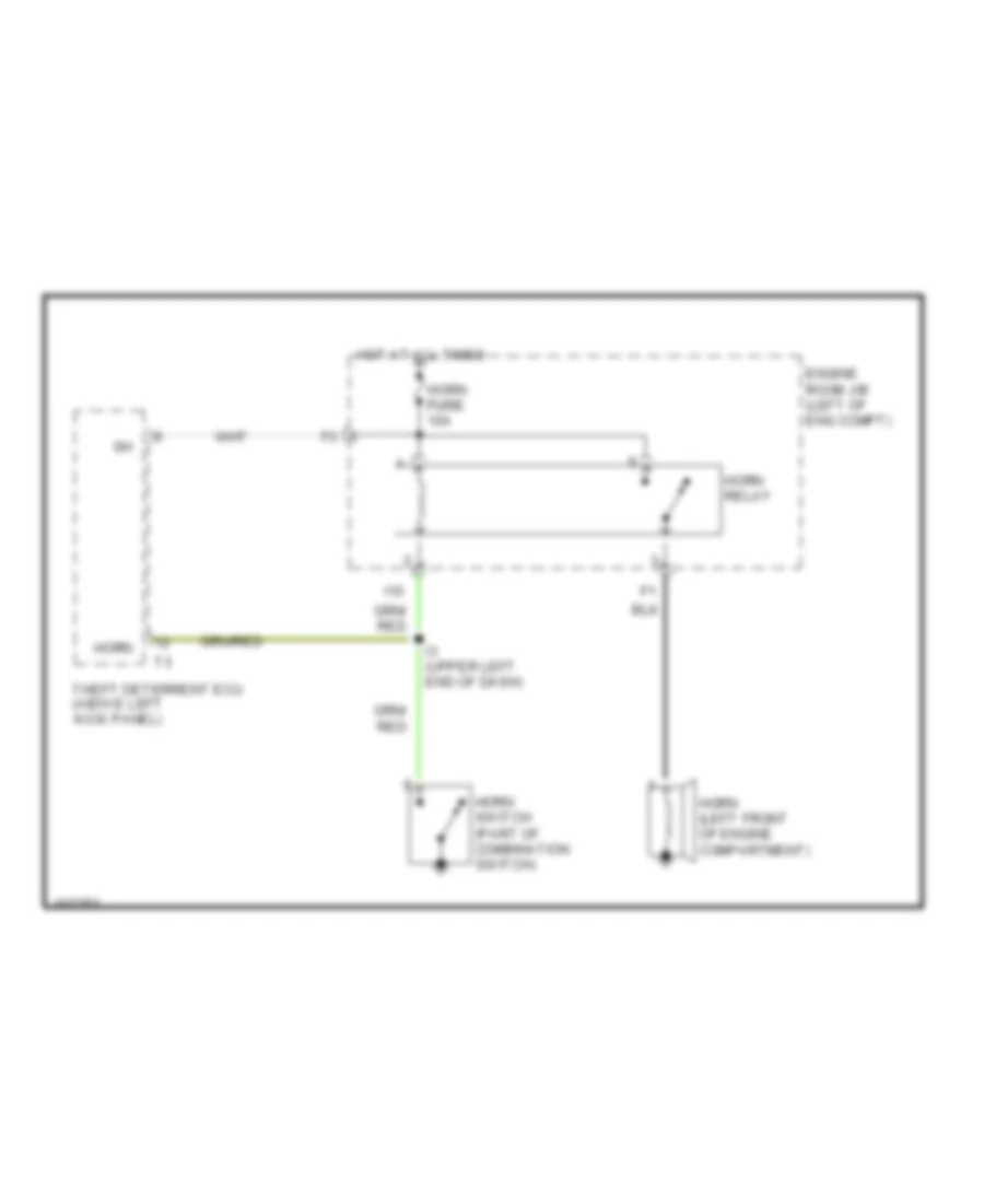
Horn Wiring Diagram for Toyota Corolla LE 2000
List of elements for Horn Wiring Diagram for Toyota Corolla LE 2000:
- Engine room j/b (left of eng compt)
- Horn
- Horn (left front of engine compartment)
- Horn fuse fuse 10a
- Horn relay
- Horn switch (part of combination switch)
- Hot at all times
- I10
- I3 (upper left end of dash)
- Theft deterrent ecu (above left kick panel)
INSTRUMENT CLUSTER
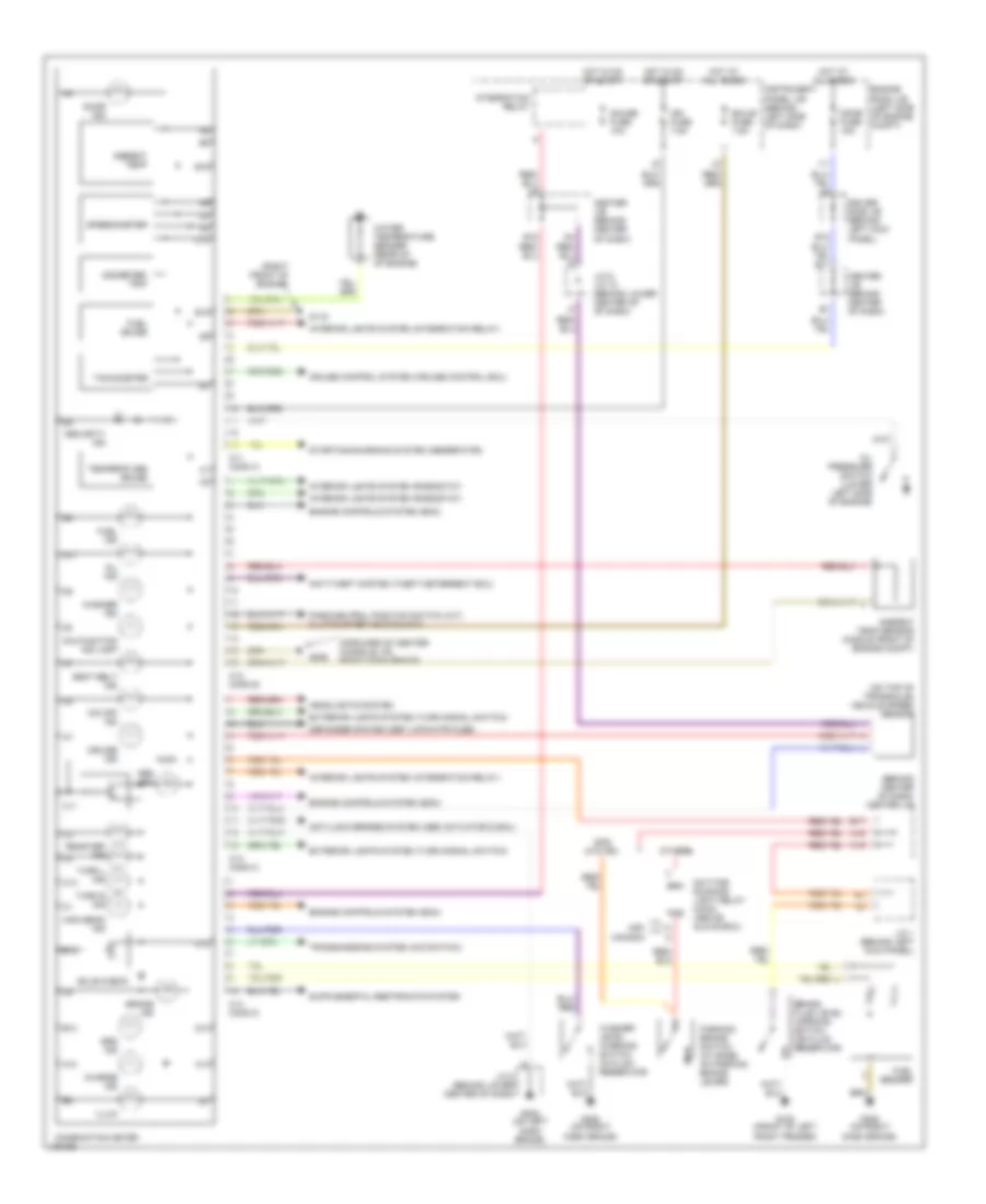
Instrument Cluster Wiring Diagram for Toyota Corolla LE 2000
List of elements for Instrument Cluster Wiring Diagram for Toyota Corolla LE 2000:
- (behind center of dash) center j/b
- (forward of center console, on right dash brace)
- (on top of transaxle) vehicle speed sensor
- (right front of engine)
- A10
- A11
- A13
- A16
- Abs ind
- Ambient temp
- Ambient temp sensor (middle front of engine compt)
- Anti-lock brakes system (abs actuator & ecu)
- Anti-theft system (theft deterrent ecu)
- B12
- B13
- B15
- B16
- B17
- B18
- Brake fluid level warning switch (on fluid reservoir)
- Brake ind
- Brk
- Bulb check
- C10
- C11
- C11 conn a
- C12
- C12 conn b
- C13
- C13 conn c
- C14 conn d
- C16
- Center j/b (behind center of dash)
- Charge ind
- Combination meter
- Cruise control system (cruise control ecu)
- Cruise ind
- D10
- Daytime running light relay (main) (above glove box)
- Defogger system (def i-up/m-htr fuse)
- Dome fuse 15a
- Door ind
- Driver side j/b (behind left kick panel)
- E10
- Ecu-b fuse 7.5a
- Engine controls system (ecm)
- Engine room j/b (left side of engine compt)
- Exterior lights system (turn signal switch)
- Fuel gauge
- Fuel ind
- Fuel sender
- G100 (front of left front fender)
- G119
- G205 (on left dash brace)
- G206
- G206 (on right dash brace)
- Gauge fuse 10a
- Headlights system
- High beam ind
- Hot at all times
- Hot in on or start
- I11
- Ign fuse 7.5a
- Illum
- Instrument panel j/b (behind left side of dash)
- Integration relay
- Interior lights system (integration relay)
- Interior lights system (rheostat)
- J/c 1 (behind left kick panel)
- J/c 8 (behind lower center of dash)
- J/c 9, j/c 10 (behind lower center of of dash)
- Malfunction ind lamp
- O/d off ind
- Odometer/ trip
- Oil ind
- Oil pressure switch (lower left side of engine)
- Others
- Park/neutral position switch (a/t) clutch start switch (m/t)
- Parking brake switch (at base of parking brake lever)
- Pkb
- Rear def ind
- Seat belt ind
- Security ind
- Speedometer
- Srs ind
- Starting/charging system (generator)
- Tachometer
- Temperature gauge
- Transmissions system (o/d switch)
- Turn l ind
- Turn r ind
- Usa canada
- W/o drl
- Washer ind
- Washer level warning switch (in fluid reservoir)
- Water temperature sender (rear of of engine)
INTERIOR LIGHTS
Courtesy Lamps Wiring Diagram for Toyota Corolla LE 2000
List of elements for Courtesy Lamps Wiring Diagram for Toyota Corolla LE 2000:
- B1 (body harn, center of windshield header)
- B11
- C10
- C11
- Center j/b (behind center of dash)
- Combination meter
- Diode (behind left side of dash)
- Dome fuse 15a
- Door
- Driver side j/b (behind left kick panel)
- E10
- E12
- Engine room j/b (left side of engine compartment)
- F11
- G200 (left kick panel)
- Hot at all times
- I11
- I12
- Ignition key cylinder light
- Instrument panel j/b (behind left side of dash)
- Integration relay
- Interior light
- J/c 18 (bottom of left "c" pillar)
- J/c 4, j/c 5 (behind upper left side of dash)
- J/c 7 (behind upper center of dash)
- Japan prod
- Left front door courtesy switch
- Left rear door courtesy switch
- Luggage compartment light
- Luggage compartment light switch
- Off
- Open door warning light
- Personal light (w/ moon roof) (part of moon roof control switch)
- Right front door courtesy switch
- Right rear door courtesy switch
- U.s. prod
- W/ auto antenna
- W/ door locks
- W/ moonroof
- W/ theft
- W/o auto antenna
- W/o theft & w/o door locks,
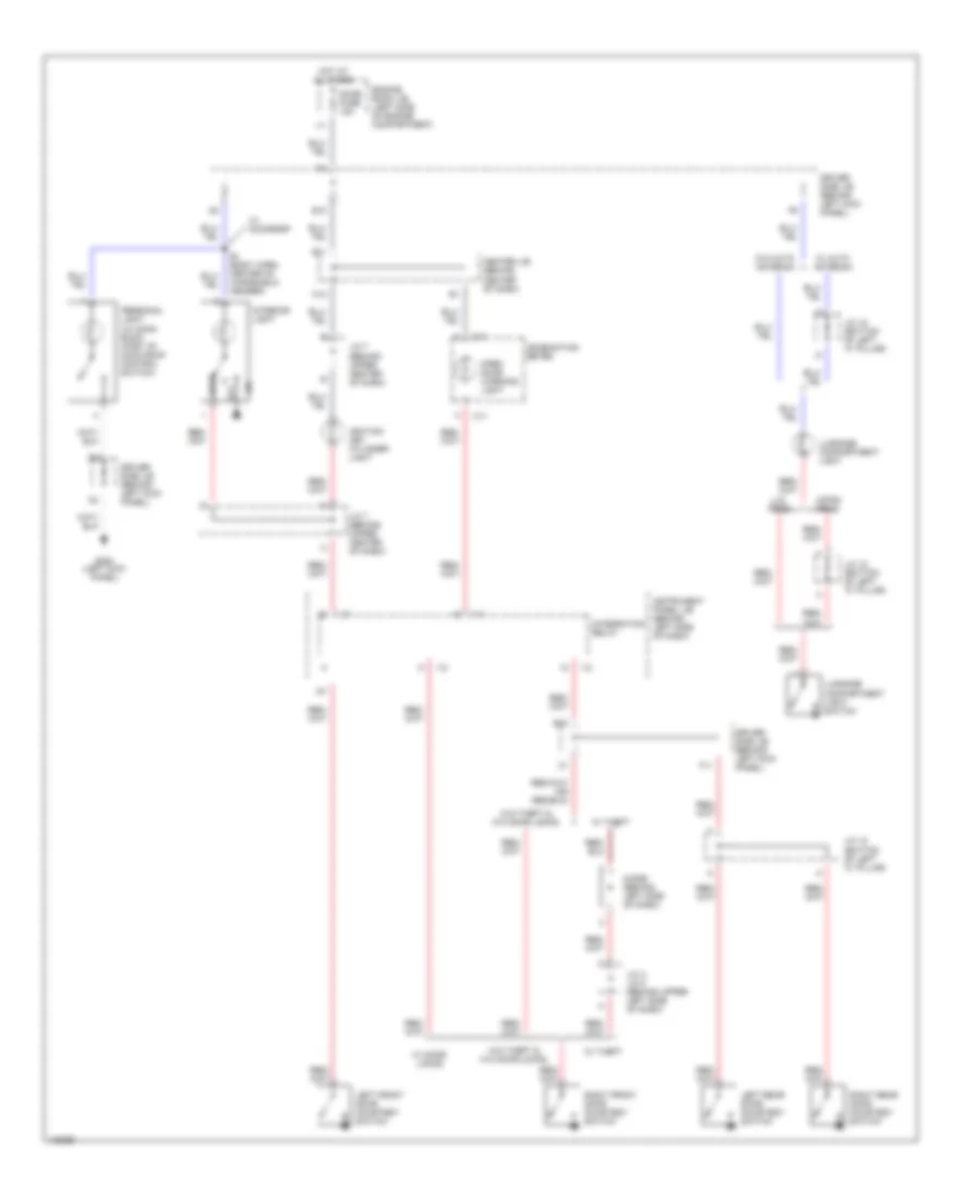
Instrument Illumination Wiring Diagram for Toyota Corolla LE 2000
List of elements for Instrument Illumination Wiring Diagram for Toyota Corolla LE 2000:
- A/c switch
- A/t shift lever illum
- A11
- A12
- A14
- A15
- A20
- Alt fuse 100a
- Ashtray illum
- B12
- B15
- Blower switch
- C12
- C17
- C18
- C20
- C21
- Center j/b (behind center of dash)
- Cigarette lighter illum
- Combination meter
- D14
- D15
- D17
- D18
- Driver side j/b (left kick panel)
- Exterior lights system
- Fusible link box (top left side of engine room j/b)
- G205
- Hazard switch
- Hot at all times
- I11
- Instrument panel j/b (behind left side of dash, at lower finish panel)
- Integration relay
- J/c 8 (behind lower center of dash)
- Meter ilum
- Radio & player
- Rear window defogger switch
- Rheostat
- Tail fuse 15a
- Taillight relay
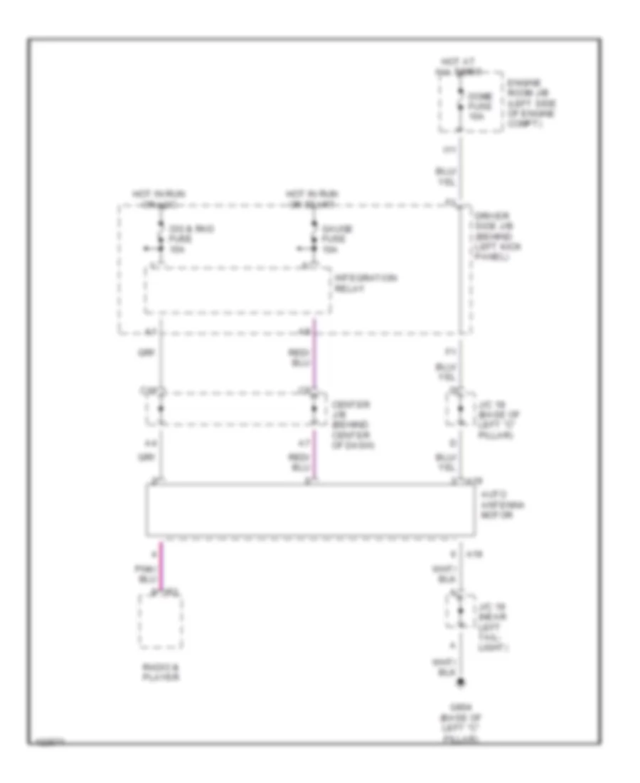
POWER ANTENNA
Power Antenna Wiring Diagram for Toyota Corolla LE 2000
List of elements for Power Antenna Wiring Diagram for Toyota Corolla LE 2000:
- A19
- Auto antenna motor
- C19
- Center j/b (behind center of dash)
- Cig & rad fuse 15a
- Dome fuse 10a
- Driver side j/b (behind left kick panel)
- Engine room j/b (left side of engine compt)
- G904 (base of left "c"
- Gauge fuse 10a
- Hot at all times
- Hot in run or acc
- Hot in run or start
- I11
- Integration relay
- J/c 18 (base of left "c" pillar)
- J/c 19 (near left tail- light)
- Pillar)
- Radio & player
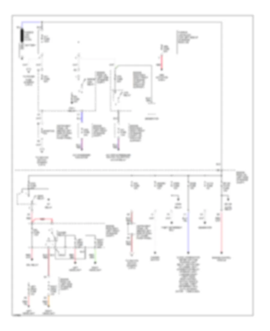
POWER DISTRIBUTION
Power Distribution Wiring Diagram (1 of 2) for Toyota Corolla LE 2000
List of elements for Power Distribution Wiring Diagram (1 of 2) for Toyota Corolla LE 2000:
- (1999 & 2000)
- A/c condenser fan motor
- A/c fuse 7.5a
- A/c triple pressure switch, a/c switch, a/c m/g relay
- Abs actuator & ecu
- Abs fuse 50a
- Alt fuse 100a
- Alt-s fuse 5a
- Am1 fuse 50a
- Am2 fuse 15a
- Battery
- Cds fuse 30a
- Clock, combination meter, daytime running light relay, ignition key cylinder light, integration relay, interior light, luggage compt light, moon roof control switch, radio & player, theft deterrent ecu, auto antenna
- Dimmer relay
- Dome fuse 15a
- Drl fuse 7.5a
- Drl relay
- Efi or
- Efi or f-htr fuse 15a
- Engine control module
- Engine main relay
- Engine room j/b (left side of engine compt)
- Engine room r/b 5 (left front of engine compt)
- Engine room r/b 6 (right front of engine compt, on radiator support)
- F-htr relay
- Fan 1 relay
- Fuse (diagram 2 of 2)
- Fusible link block (top left side of of engine room j/b)
- Fusible link main (12 ga)
- Generator
- Hazard fuse 10a
- Hazard switch
- Head relay
- Horn
- Horn fuse 10a
- Htr fuse 50a
- Htr relay
- I11
- Instrument panel j/b (behind left side of dash, at lower finish panel)
- Left head fuse 10a
- Left headlight
- Main fuse 40a
- Motor
- Rdi fuse 30a
- Red
- Relay
- Right head fuse 10a
- Right headlight
- Shorting pin
- Theft deterrent ecu
- To ignition switch (diagram 2 of 2)
- To power
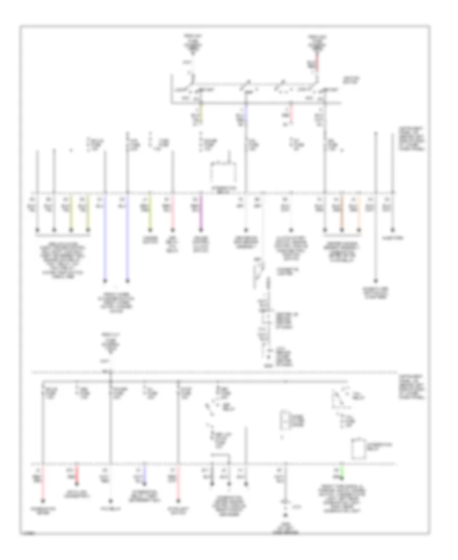
Power Distribution Wiring Diagram (2 of 2) for Toyota Corolla LE 2000
List of elements for Power Distribution Wiring Diagram (2 of 2) for Toyota Corolla LE 2000:
- 7.5a
- A19
- Abs actuator & ecu, cruise control ecu, shift lock ecu, theft deterrent ecu, engine main relay, fan 1 relay, a/c fan 2 relay, water temp switch (1998 & 1999)
- Acc
- C13
- Center air bag sensor assembly
- Center air bag sensor assembly, combination meter, efi or f-htr relay
- Center j/b (behind center of dash)
- Cig fuse 15a
- Cigarette lighter
- Clutch start switch, engine control module, park/neutral position switch
- Combination meter
- Combination meter, engine control module, rear window defogger
- Cruise control clutch switch
- D/l fuse 30a
- Data link connector 3
- Def fuse 40a
- Def i-up/ m-htr fuse 10a
- Def relay
- Def relay, p/w relay
- E10
- E11
- Ecu-b fuse 7.5a
- Ecu-ig fuse 10a
- From alt
- From am1
- From am2 fuse (diagram 1 of 2) c
- Front turn signal & parking lights, hazard switch, license plate light, left rear combination light, right rear combination light
- Front wiper & washer switch, front wiper motor, washer motor
- Fuse (diagram 1 of 2) a
- Fuse (diagram 1 of 2) b
- G205
- G205 (on left dash brace)
- Gauge fuse 10a
- Hazard switch
- Ign fuse 7.5a
- Ignition switch
- Injectors
- Instrument panel j/b (behind left side of dash, at lower finish panel)
- Integration relay
- Integration relay, theft deterrent ecu
- J/c 8
- J/c 8 (behind lower center of dash)
- Lock
- Noise filter (dome)
- Noise filter, ignition coil & igniters
- Obd fuse 7.5a
- P/w relay
- Power fuse 30a
- Red
- St fuse 5a
- Start
- Stop fuse 15a
- Stoplight switch
- Tail fuse 15a
- Tail relay
- Turn fuse
- Wip fuse 20a
POWER DOOR LOCKS
Power Door Lock Wiring Diagram, NUMMI Made for Toyota Corolla LE 2000
List of elements for Power Door Lock Wiring Diagram, NUMMI Made for Toyota Corolla LE 2000:
- B red
- D/l fuse 30a
- Detect
- Driver side j/b (behind left kick panel)
- G200 (left kick panel)
- G203
- G205
- Hot at all times
- I11
- I12
- Instrument panel j/b (behind left side of dash)
- Integration relay
- J/c 14 (behind right kick panel)
- J/c 15 (w/o pwr windows) (in left front door)
- J/c 16 (w/ pwr windows) (in left front door)
- J/c 17 (in right front door)
- J/c 3 (behind upper left side of dash)
- J/c 4, j/c 5 (behind upper left side of dash)
- J/c 8 (behind lower center of dash)
- Left door lock control unlk switch
- Left front door lock motor, unlock detection switch, door key lock/unlock switch
- Left rear door lock motor
- Lock
- Red
- Right door lock control lock switch
- Right front door lock motor & door key lock/ unlock switch
- Right rear door lock motor
- Unlk
- Unlock warning switch
- W/ power windows
- W/o power windows
Power Door Lock Wiring Diagram, TMMC Made for Toyota Corolla LE 2000
List of elements for Power Door Lock Wiring Diagram, TMMC Made for Toyota Corolla LE 2000:
- Anti- theft system
- C10
- D/l fuse 30a
- Detect
- Driver side j/b (behind left kick panel)
- G200 (left kick panel)
- G203
- G205
- Hot at all times
- I11
- I12
- Instrument panel j/b (behind left side of dash)
- Integration relay
- J/c 14 (behind right kick panel)
- J/c 15 (w/o pwr windows) (in left front door)
- J/c 16 (w/ pwr windows) (in left front door)
- J/c 17 (in right front door)
- J/c 3 (behind upper left side of dash)
- J/c 4, j/c 5 (behind upper left side of dash)
- J/c 8 (behind lower center of dash)
- Left door key lock/ unlock lock switch
- Left door lock control unlk switch
- Left front door lock motor (power window master switch)
- Left rear door lock motor
- Lock
- Red
- Right door key lock/ unlock switch
- Right door lock control lock switch
- Right front door lock motor
- Right rear door lock motor
- Unlk
- Unlock warning switch
- W/ power windows
- W/o power windows
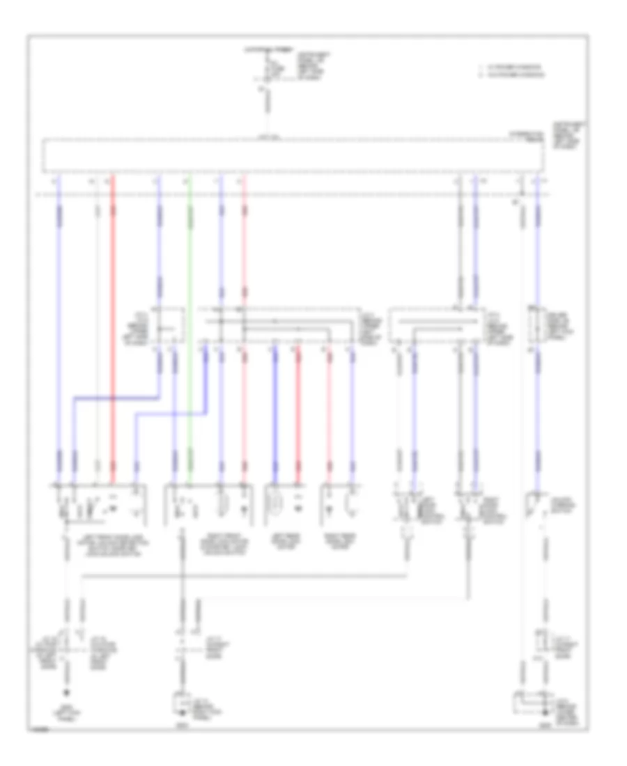
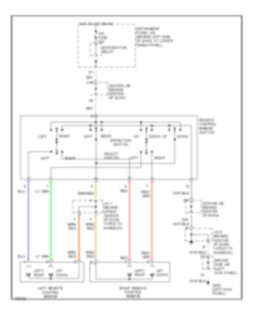
POWER MIRRORS
Power Mirror Wiring Diagram for Toyota Corolla LE 2000
List of elements for Power Mirror Wiring Diagram for Toyota Corolla LE 2000:
- C19
- C20
- Center j/b (behind center of dash)
- Center j/b (behind center of dash)
- Cig fuse 15a
- Down
- Driver side j/b (left kick panel)
- G200 (left kick panel)
- Hot in acc or on
- Instrument panel j/b (behind left side of dash, at lower finish panel)
- Integration relay
- J/c 7 (behind upper center of dash, taped to harness)
- J/c 8 (behind center of dash, taped to harness)
- Left
- Left remote control mirror
- Left/ right
- Operation switch
- Red
- Remote control mirror switch
- Right
- Right remote control mirror
- Select switch
- Up/ down
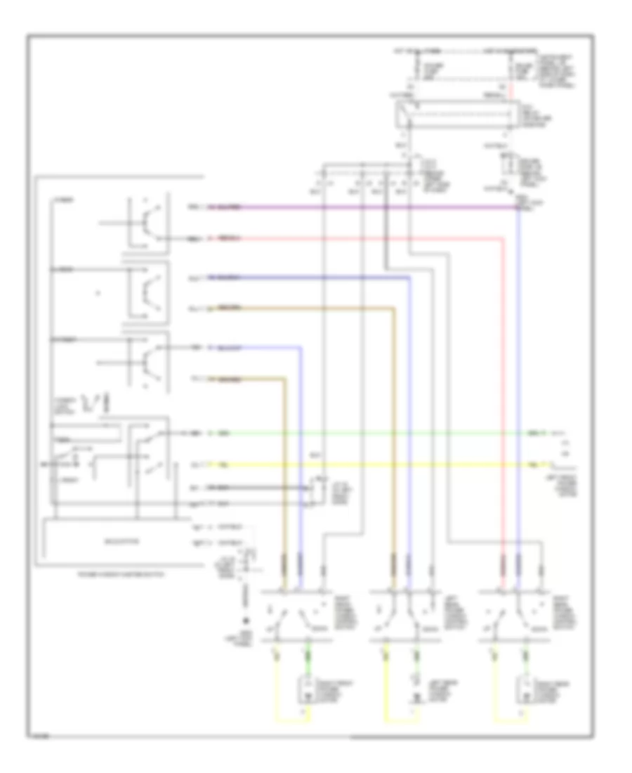
POWER TOP/SUNROOF
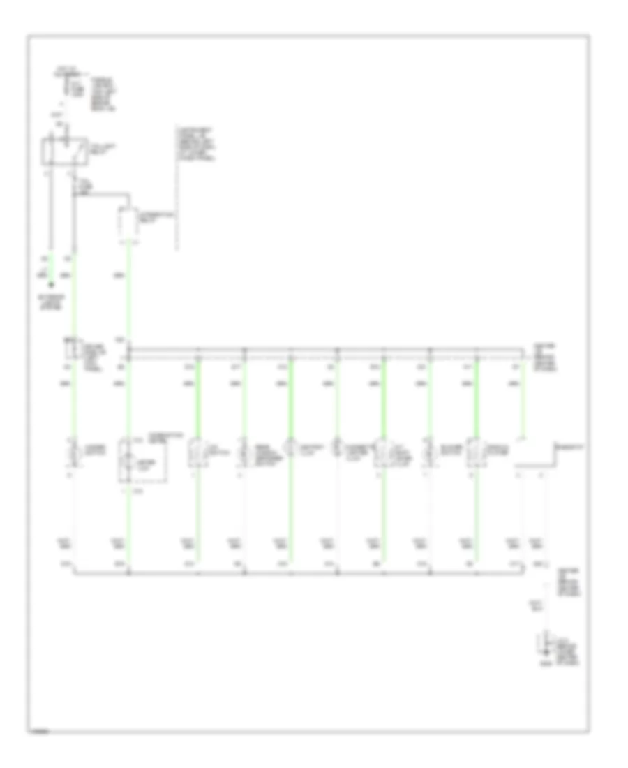
Moonroof Wiring Diagram for Toyota Corolla LE 2000
List of elements for Moonroof Wiring Diagram for Toyota Corolla LE 2000:
- Close
- D j4
- Down
- Driver side j/b (behind left kick panel)
- Driver side r/b (left kick panel)
- E j5
- G200 (left kick panel)
- Gauge fuse 10a
- Header)
- Hot at all times
- Hot in on or start
- Instrument panel j/b (behind left side of dash, at lower finish panel)
- J/c 4, j/c 5 (behind upper left side of dash, taped to harness)
- Moon roof control switch
- Moon roof motor & limit switch (front center of roof)
- Moon roof control relay (center of windshield header)
- No.
- Open
- Pnk
- Power fuse 30a
- Power main relay
- Red
- Solid state
- W/ power window
- W/o power window
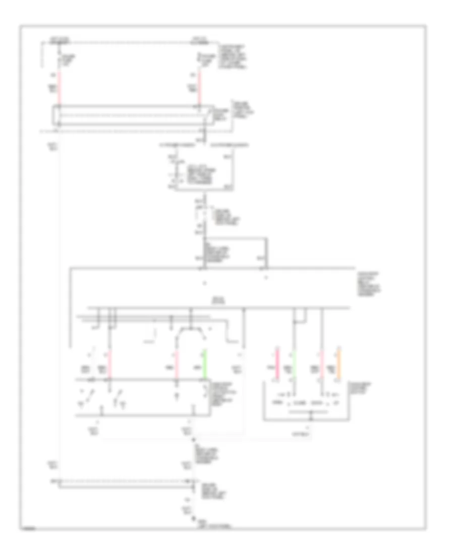
POWER WINDOWS
Power Window Wiring Diagram for Toyota Corolla LE 2000
List of elements for Power Window Wiring Diagram for Toyota Corolla LE 2000:
- Down
- Driver side j/b (behind left kick panel)
- G200 (left kick panel)
- Gauge fuse 10a
- Hot at all times
- Hot in on or start
- Instrument panel j/b (behind left side of dash, at lower finish panel)
- J/c 16 (in left front door)
- J/c 4, j/c 5 (behind upper left side of dash)
- L front
- L rear
- Left front power window motor
- Left rear power window control switch
- Left rear power window motor
- Lock
- Normal
- P/w relay (on driver side r/b)
- Power fuse 30a
- Power window master switch
- R front
- R rear
- Right rear power window control switch
- Right front power window control switch
- Right front power window motor
- Right rear power window motor
- Rld
- Rlu
- Rrd
- Rru
- Solid state
- Window lock switch
RADIO
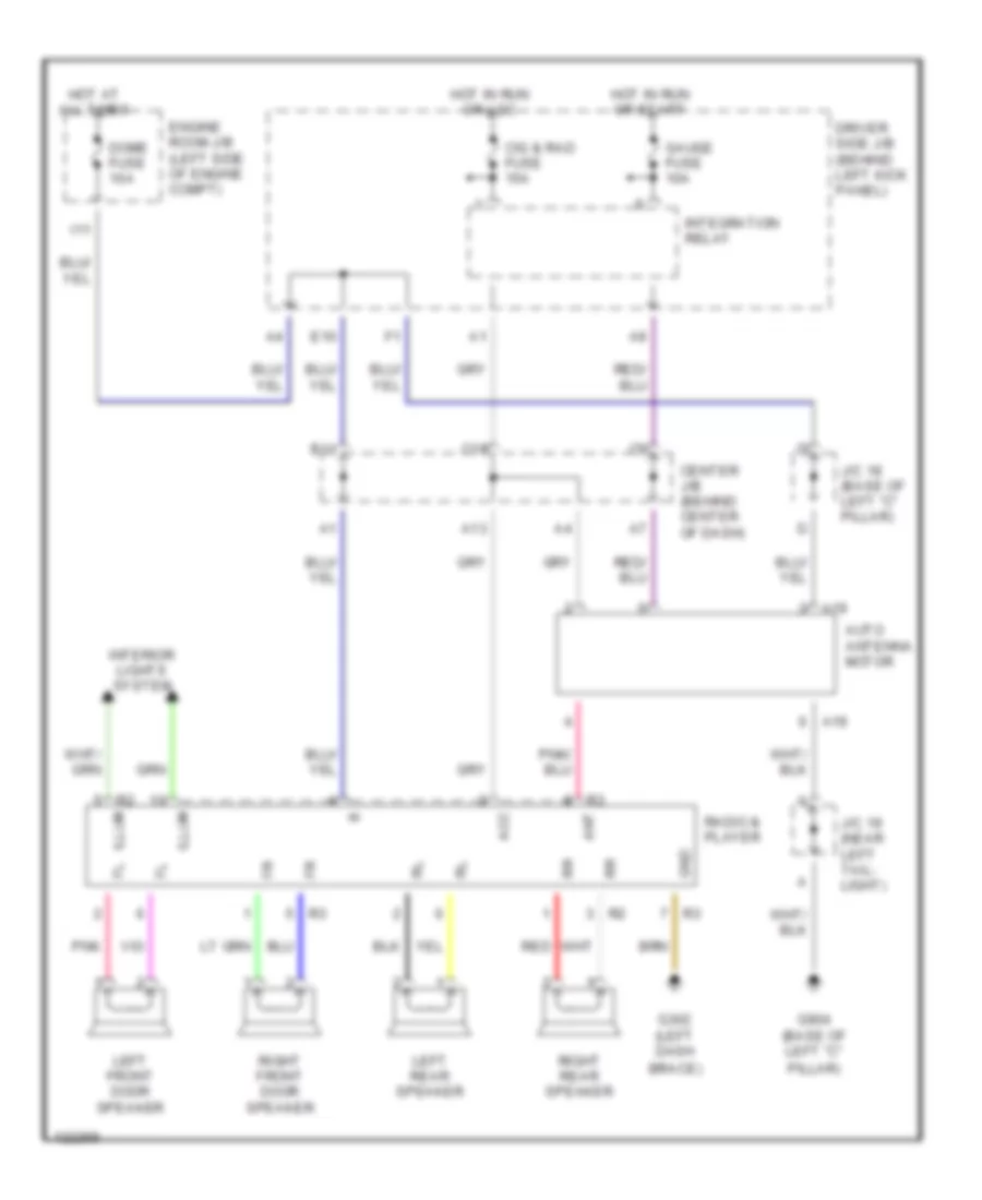
Radio Wiring Diagrams for Toyota Corolla LE 2000
List of elements for Radio Wiring Diagrams for Toyota Corolla LE 2000:
- A13
- A19
- Acc
- Ant
- Auto antenna motor
- B11
- Brace)
- C19
- Center j/b (behind center of dash)
- Cig & rad fuse 15a
- Dome fuse 10a
- Driver side j/b (behind left kick panel)
- E10
- Engine room j/b (left side of engine compt)
- G302 (left dash
- G904 (base of left "c"
- Gauge fuse 10a
- Gnd
- Hot at all times
- Hot in run or acc
- Hot in run or start
- I11
- Illum
- Integration relay
- Interior lights system
- J/c 18 (base of left "c" pillar)
- J/c 19 (near left tail- light)
- Left front door speaker
- Left rear speaker
- Pillar)
- Pnk
- Radio & player
- Red
- Right front door speaker
- Right rear speaker
SHIFT INTERLOCKS
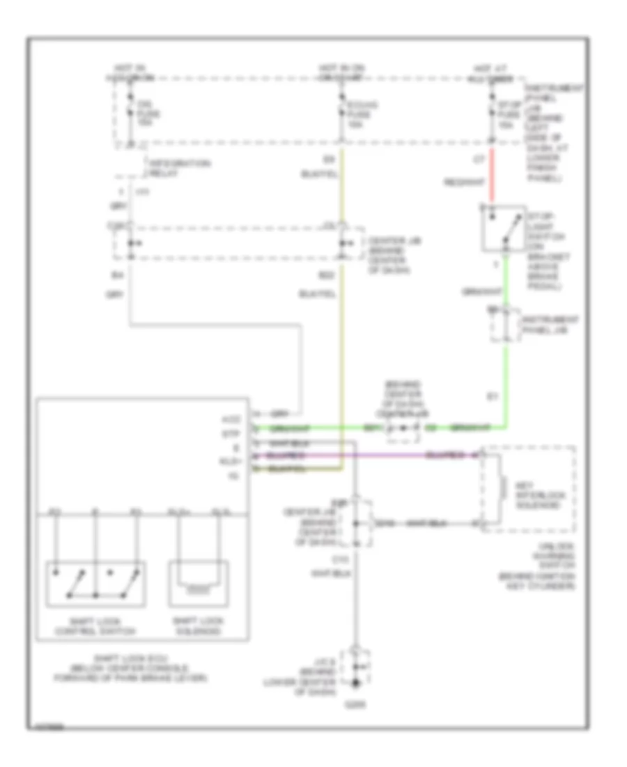
Shift Interlock Wiring Diagram for Toyota Corolla LE 2000
List of elements for Shift Interlock Wiring Diagram for Toyota Corolla LE 2000:
- (behind center of dash) center j/b
- Acc
- B20
- B21
- B22
- C13
- C19
- Center j/b (behind center of dash)
- Cig fuse 15a
- D10
- Ecu-ig fuse 10a
- G205
- Hot at all times
- Hot in acc or on
- Hot in on or start
- I11
- Instrument panel j/b
- Instrument panel j/b (behind left side of dash, at lower finish panel)
- Integration relay
- J/c 8 (behind lower center of dash)
- Key interlock solenoid
- Kls+
- Shift lock control switch
- Shift lock ecu (below center console, forward of park brake lever)
- Shift lock solenoid
- Sls+
- Sls-
- Stop fuse 15a
- Stop- light switch (on bracket above brake pedal)
- Stp
- Unlock warning switch (behind ignition key cylinder)
STARTING/CHARGING
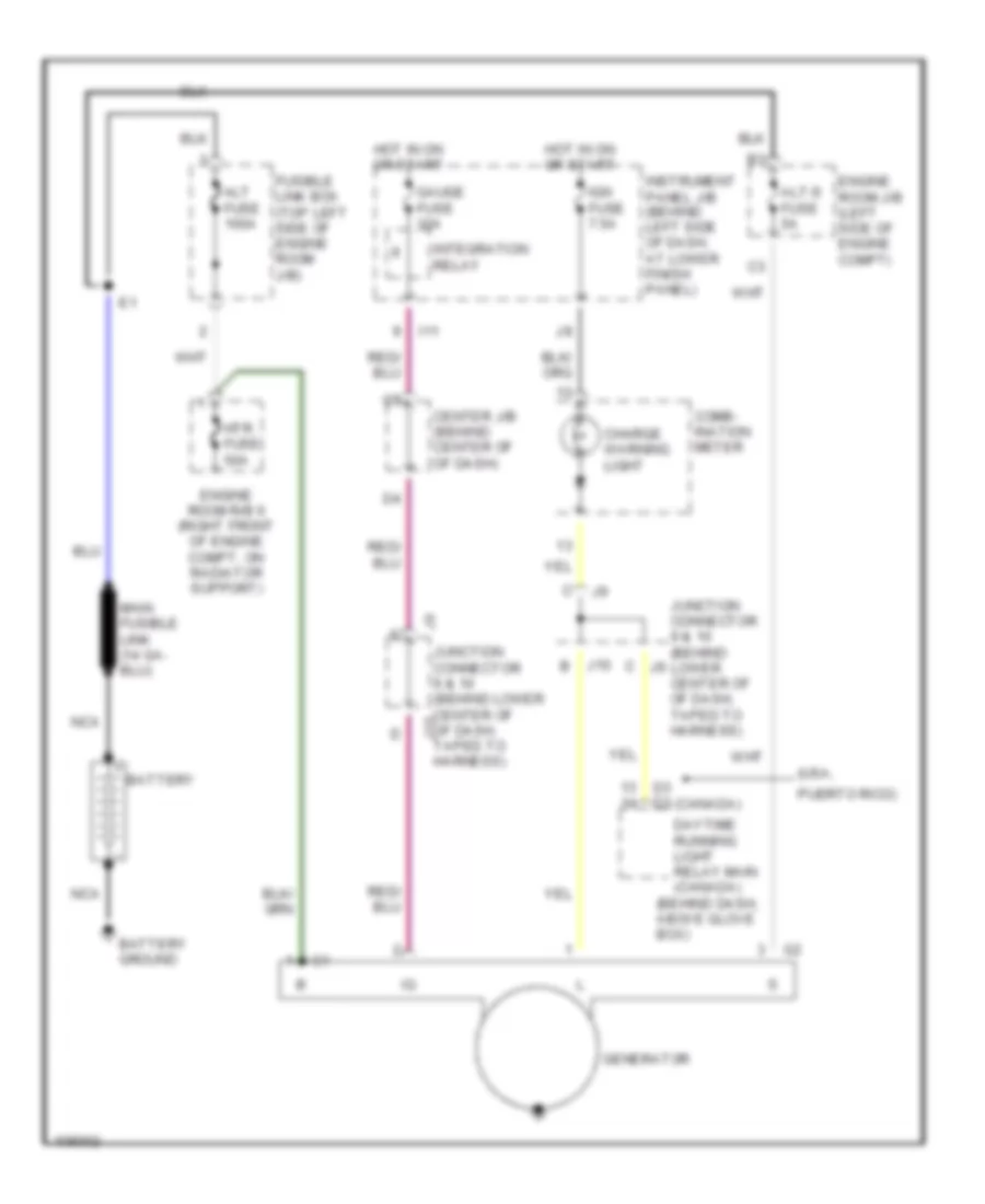
Charging Wiring Diagram for Toyota Corolla LE 2000
List of elements for Charging Wiring Diagram for Toyota Corolla LE 2000:
- (behind dash, above glove box)
- (usa,
- Alt fuse 100a
- Alt-s fuse 5a
- Battery
- Battery ground
- Center j/b (behind center of of dash)
- Charge warning light
- Comb- ination meter
- D3 d3 (canada)
- Daytime running light relay main (canada)
- Engine room j/b (left side of engine compt)
- Engine room r/b 6 (right front of engine compt, on radiator support)
- Fusible link box (top left side of engine room j/b)
- Gauge fuse 10a
- Generator
- Hot in on or start
- Htr fuse 50a
- I11
- Ign fuse 7.5a
- Instrument panel j/b (behind left side of dash, at lower finish panel)
- Integration relay
- J10
- Junction connector 9 & 10 (behind j9 lower center of of dash, taped to harness)
- Junction connector 9 & 10 (behind lower center of j10 of dash, taped to harness)
- Nca
- Puerto rico)
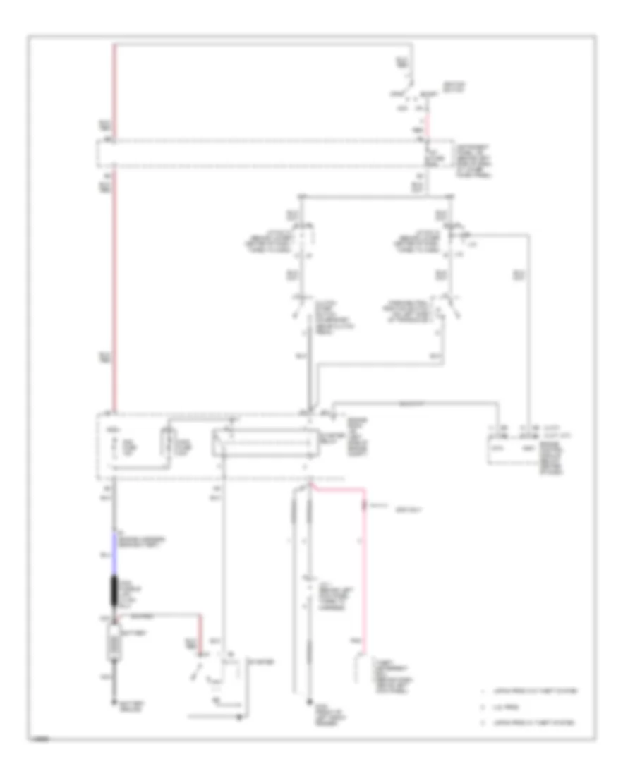
Starting Wiring Diagram for Toyota Corolla LE 2000
List of elements for Starting Wiring Diagram for Toyota Corolla LE 2000:
- (3 a/t, m/t)
- (4 a/t)
- 2000 only
- A/t
- Acc
- Am2 fuse 15a
- Battery
- Battery ground
- Clutch start switch (on bracket, above clutch pedal)
- E1 (engine harness, near battery)
- E11
- Engine control module (below center of dash)
- Engine room j/b (left side of engine compt)
- G100 (front of left front fender)
- Ignition switch
- Instrument panel j/b (behind left side of dash, at lower finish panel)
- J/c 1 (behind left kick panel taped to harness)
- J/c 9 & 10 (behind lower center of dash, taped to harn)
- J10
- Japan prod w/ theft system
- Japan prod w/o theft system
- M/t
- Main fuse 40a
- Nca
- Nsw
- Off
- P/ n
- Park/neutral position switch (on left side of transaxle)
- Pnk
- Red
- St fuse 5a
- Sta
- Start
- Starter
- Starter relay
- Theft deterrent ecu (behind dash, above left kick panel)
- U.s. prod
SUPPLEMENTAL RESTRAINTS
Supplemental Restraint Wiring Diagram for Toyota Corolla LE 2000
List of elements for Supplemental Restraint Wiring Diagram for Toyota Corolla LE 2000:
- (left dash panel brace) g206
- +sl
- +sr
- -sl
- -sr
- 3 a/t, m/t
- 4 a/t
- Acc
- Air bag squib (front passenger air bag assembly)
- Air bag squib (steering wheel pad)
- C12
- C13
- C14
- Center air bag sensor assembly (below front of center console)
- Center j/b (behind center of dash)
- Cig fuse 15a
- Combination meter
- Data link connector (dlc) 1 (partial) (on left rear of engine compartment)
- Data link connector (dlc) 3 (partial) (below left side of dash)
- Ecu-b fuse 7.5a
- Engine control module (below center of dash)
- Esl
- Esr
- F/fps
- Fl+
- Fl-
- Fr+
- Fr-
- Fsl
- Fsr
- G206 (left dash panel brace)
- Gsw2
- Hot at all times
- Hot in acc or on
- Hot in on or start
- Ig2
- Ign fuse 7.5a
- Instrument panel j/b (behind left side of dash, at lower finish panel)
- J/c 13 (behind upper right side of dash)
- J/c 6 (behind upper center of dash, taped to harness)
- J/c 7 (behind upper center of dash, taped to harness)
- J/c 8 (behind lower center of dash, taped to harness)
- Lbe+
- Left buckle switch (in driver's seat belt buckle)
- Left front air bag sensor (behind left headlight assembly)
- Left pretensioner (at bottom of left "b" pillar)
- Left side air bag sensor (if equipped) (on left side door sill plate area)
- Left side air bag squib (if equipped)
- Model
- Pl+
- Pl-
- Pnk
- Pr+
- Pr-
- Red
- Right front air bag sensor (behind right headlight assembly)
- Right pretensioner (at bottom of right "b" pillar)
- Right side air bag sensor (if equipped) (on right side door sill plate area)
- Right side air bag squib (if equipped)
- Sil
- Spiral cable
- Srs warning light
- Ssl
- Ssl+
- Ssr
- Ssr+
- Vupl
- Vupr
TRANSMISSION
A/T Wiring Diagram for Toyota Corolla LE 2000
List of elements for A/T Wiring Diagram for Toyota Corolla LE 2000:
- (left dash brace)
- (left side of transaxle) park/neutral position switch
- B18
- B19
- Batt
- C10
- C12
- C13
- C14
- Center j/b (behind center of dash)
- Combination meter
- Cruise control ecu (behind right kick panel)
- Cruise control system
- Data link connector 1 (left rear of engine compt)
- E01
- E02
- E03
- E10
- E11
- Efi or f-htr fuse 15a
- Efi or f-htr relay
- Electronically controlled transmission solenoid
- Engine control module (below center of dash)
- Engine coolant
- Engine room j/b (left side of engine compt)
- G100 (front of left front fender)
- G119 (right front of engine)
- G205
- G206 (right dash brace)
- Gauge fuse 10a
- Hot at all times
- Hot in on or start
- Hot in start
- Idl0
- Ign fuse 7.5a
- Indicator
- Instrument panel j/b (left side of dash, at lower finish panel)
- Intergration relay
- Interior lights system
- J/c 1 (behind left kick panel)
- J/c 11 (center of dash)
- J/c 12 (center of dash)
- J/c 9, j/c 10 (center of dash)
- Japan prod
- L l
- Lockup
- Meter
- Nsw
- O/d main switch
- O/d off
- Od1
- Odlp
- Odms
- On coolant outlet)
- Others
- Spd
- Speedo-
- St fuse 5a
- Sta
- Stop fuse 15a
- Stoplight switch (on bracket, above brake pedal)
- Stp
- Te1
- Temperature sensor (rear of engine,
- Throttle position sensor (on throttle body assembly)
- Thw
- U.s. prod
- Usa w/o abs, srs, cruise, tach
- Vehicle speed sensor (on top of transaxle)
- Vta
- W/ cruise control
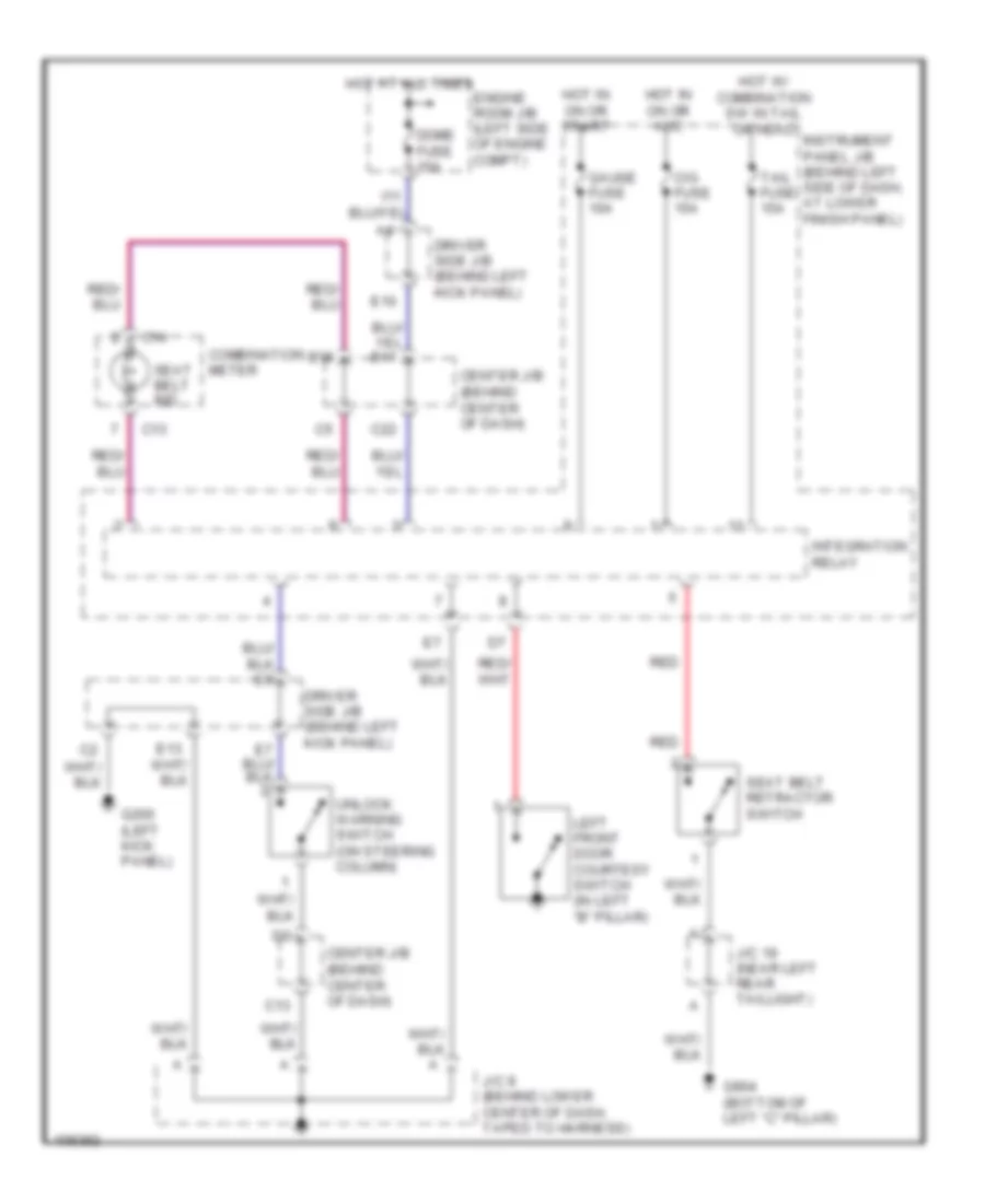
WARNING SYSTEMS
Warning System Wiring Diagrams for Toyota Corolla LE 2000
List of elements for Warning System Wiring Diagrams for Toyota Corolla LE 2000:
- B18
- C13
- C14
- C22
- Center j/b (behind center of dash)
- Cig fuse 15a
- Combination meter
- Dome fuse 15a
- Driver side j/b (behind left kick panel)
- E10
- Engine room j/b (left side of engine compt)
- G200 (left kick panel)
- G904 (bottom of left "c" pillar)
- Gauge fuse 10a
- Hot at all times
- Hot in on or acc
- Hot in on or start
- Hot w/ combination sw in tail or head
- I11
- Instrument panel j/b (behind left side of dash, at lower finish panel)
- Integration relay
- J/c 19 (near left rear taillight)
- J/c 8 (behind lower center of dash, taped to harness)
- Left front door courtesy switch (in left "b" pillar)
- Red
- Seat belt ind
- Seat belt retractor switch
- Tail fuse 15a
- Unlock warning switch (on steering column)
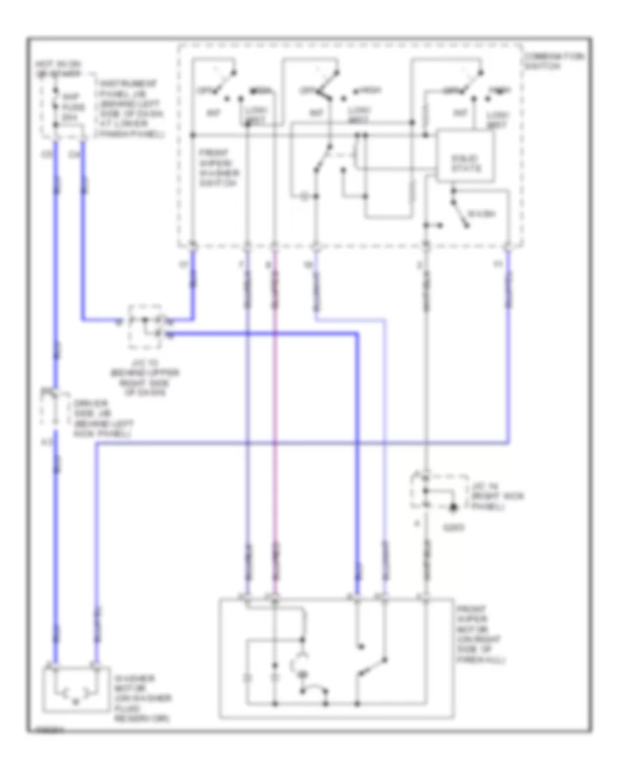
WIPER/WASHER
Wiper/Washer Wiring Diagram for Toyota Corolla LE 2000
List of elements for Wiper/Washer Wiring Diagram for Toyota Corolla LE 2000:
- Combination switch
- Driver side j/b (behind left kick panel)
- Front wiper motor (on right side of firewall)
- Front wiper/ washer switch
- G203
- High
- Hot in on or start
- Instrument panel j/b (behind left side of dash, at lower finish panel)
- Int
- J/c 13 (behind upper right side of dash)
- J/c 14 (right kick panel)
- Low/ mist
- Off
- Solid state
- Wash
- Washer motor (on washer fluid reservoir)
- Wip fuse 20a

 Čeština
 Dansk
Dansk Deutsch
 Ελληνικά
 English
 English
 Español
 Suomi
Suomi Français
 Français
 עברית
עברית Hrvatski
 Magyar
 Italiano
 日本語
日本語 한국어
한국어 Nederlands
 Português
 Português
 Română
 Русский
 Slovenčina
 Slovenščina
 Svenska
 Türkçe
 中文 (中国)