POWER DISTRIBUTION
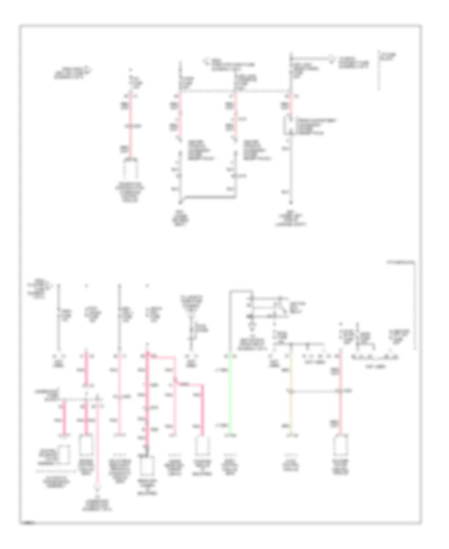
Power Distribution Wiring Diagram (1 of 4) for Chevrolet Captiva Sport LT 2013

List of elements for Power Distribution Wiring Diagram (1 of 4) for Chevrolet Captiva Sport LT 2013:
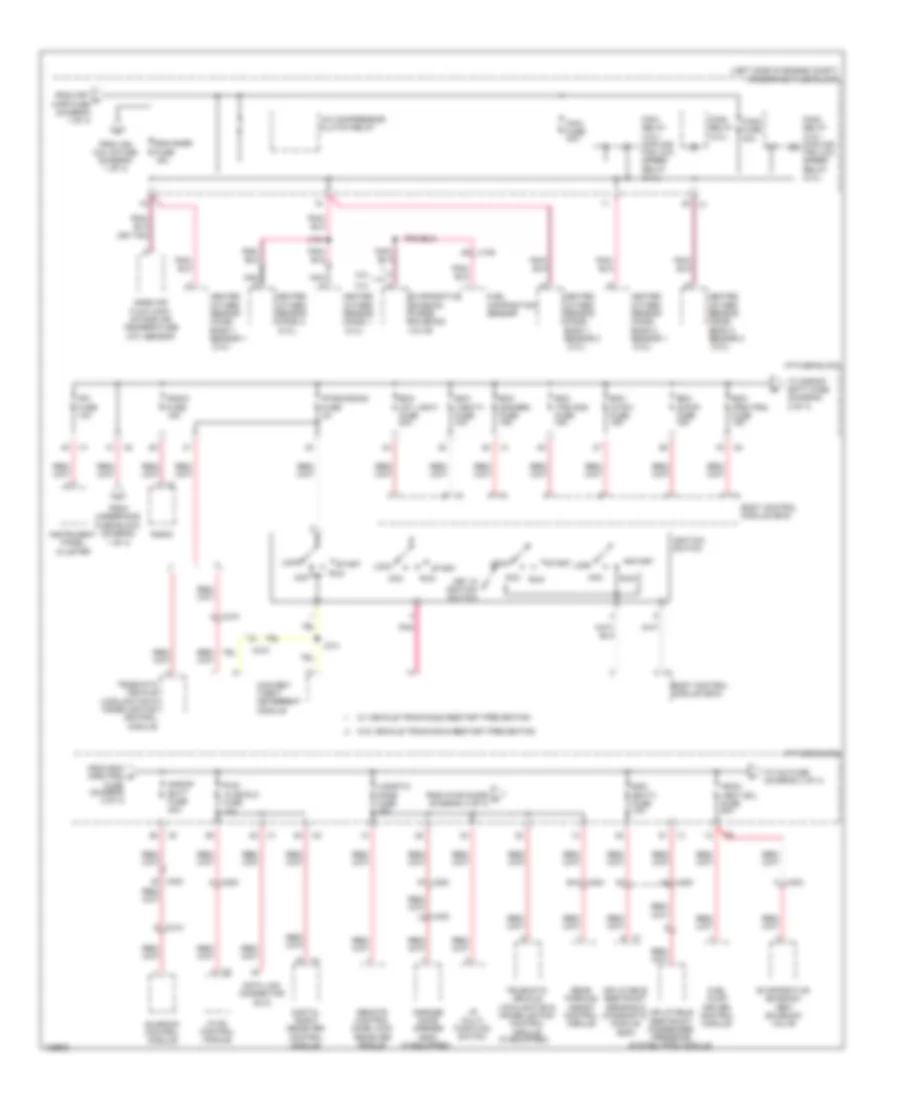
Power Distribution Wiring Diagram (2 of 4) for Chevrolet Captiva Sport LT 2013
List of elements for Power Distribution Wiring Diagram (2 of 4) for Chevrolet Captiva Sport LT 2013:
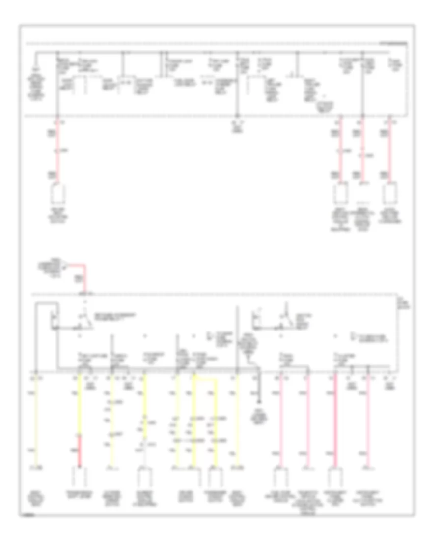
Power Distribution Wiring Diagram (3 of 4) for Chevrolet Captiva Sport LT 2013
List of elements for Power Distribution Wiring Diagram (3 of 4) for Chevrolet Captiva Sport LT 2013:
Power Distribution Wiring Diagram (4 of 4) for Chevrolet Captiva Sport LT 2013
List of elements for Power Distribution Wiring Diagram (4 of 4) for Chevrolet Captiva Sport LT 2013: