POWER DISTRIBUTION
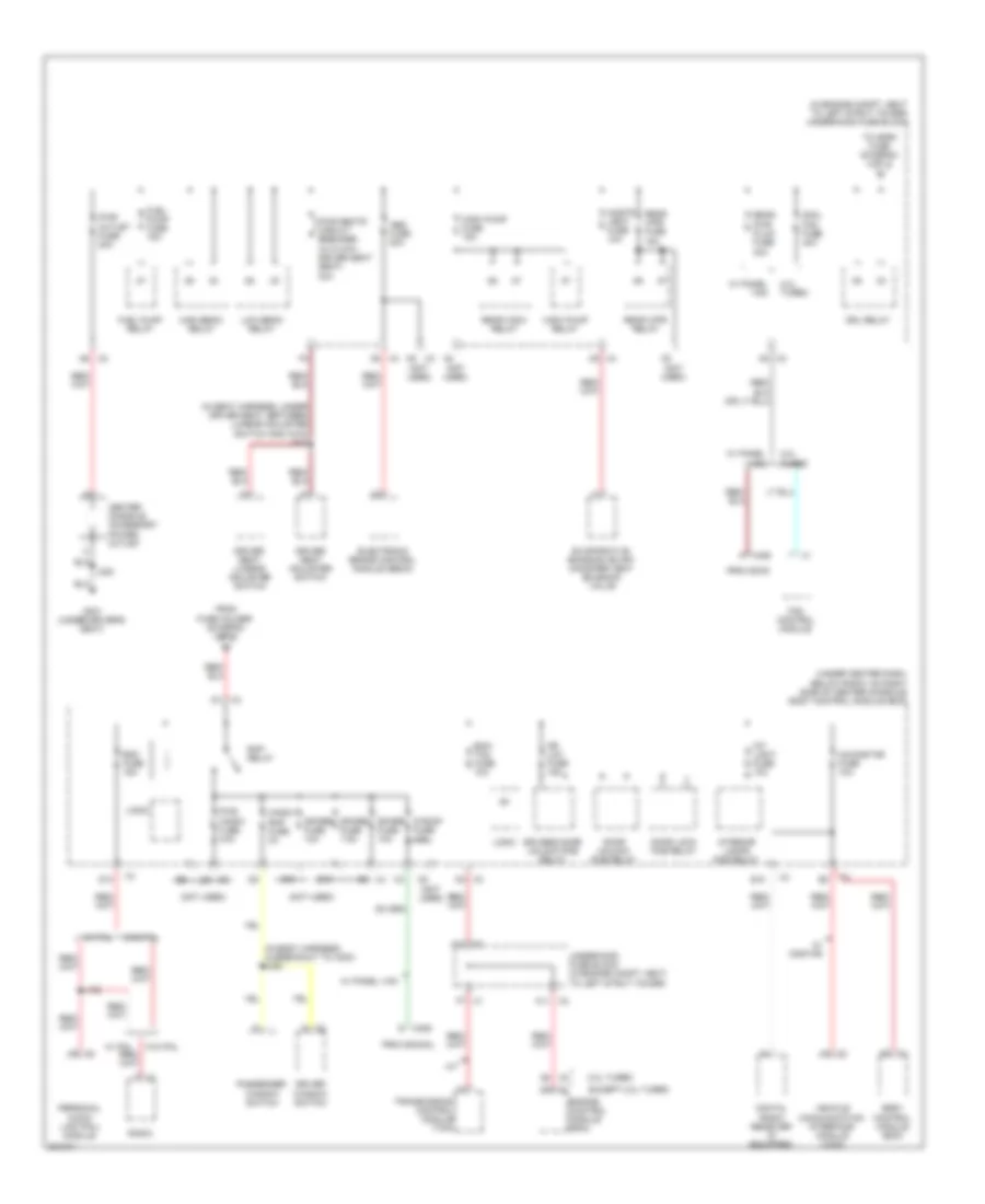
Power Distribution Wiring Diagram (1 of 4) for Chevrolet HHR SS 2009

List of elements for Power Distribution Wiring Diagram (1 of 4) for Chevrolet HHR SS 2009:
- (in engine compt, next to left strut tower) underhood fuse block
- (not used)
- (on front of engine, from starter to generator approximately 15 cm from starter) j111
- 2.0l turbo
- 50a
- A/t
- A10
- A2 x3
- Abs fuse 10a
- Abs fuse 40a
- Air bag fuse 10a
- Automatic transmission
- B11
- Back up lamp switch
- Backup/lps fuse 10a
- Battery
- Bcm2 fuse 40a
- Bcm3 fuse 30a
- Body control module (bcm)
- Body control module (bcm) (under center dash, below radio, on right side of center console)
- Cigar lighter
- Cool fan fuse 30a
- Cool fan relay (except 2.0l turbo)
- Crank fuse 30a
- Crank relay
- D10 x3
- Data link connector (dlc)
- Driver heated seat control module
- E2 x4
- Ecm trans fuse 15a
- Electronic brake control module (ebcm)
- Electronic power steering motor control module
- Engine control module (ecm)
- Eps fuse 60a
- Except 2.0l turbo
- Fog lamp fuse 15a
- Fog lamp relay (uplevel)
- Front aux pwr outlet fuse 20a
- Fuse holder
- G109 (on left front shock tower)
- G203 (behind left end of dash)
- Generator
- Htd/ seat fuse (w/ front seat heater) 20a
- Htd/seat/ fuse 10a
- Hvac relay
- I/p accessory power outlet
- I/p ign fuse 20a
- Inflatable restraint sensing & diagnostic module (sdm)
- J101
- M/t
- Mir fuse 5a
- Outside rearview mirror switch
- Park/neutral position (pnp) switch
- Passenger heated seat control module
- Pnk
- Rear defog fuse 40a
- Rear defog relay
- Red
- Run/ crank relay
- Starter
- To body control module (diagram 2 of 4)
- To body control module (diagram 3 of 4)
- To pwr/ trn relay (diagram 4 of 4)
- Transmission control module (tcm)
- W/ cigarette lighter ashtray
- W/ front seat heater
- W/o cigarette lighter ashtray
- Wiper on/off relay
- Wpr fuse 25a
- X1 b9 (not used)
- X1 c12
- X100 e
- X2 d3
- X2 f6
- X3 a3
- X3 c5
- X3 d6 (not used)
- X4 a4
- X4 b1
- X4 c2
- X4 e2
- X4 e6
- X6 a
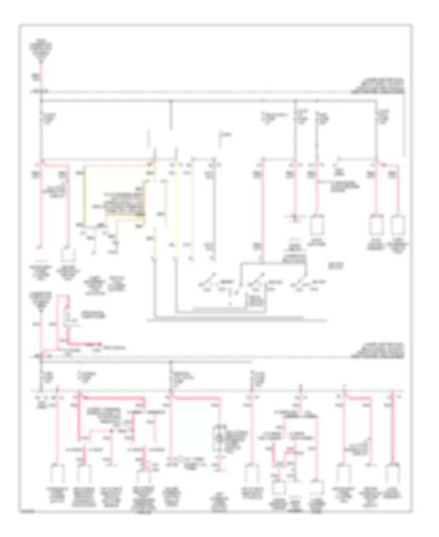
Power Distribution Wiring Diagram (2 of 4) for Chevrolet HHR SS 2009
List of elements for Power Distribution Wiring Diagram (2 of 4) for Chevrolet HHR SS 2009:
- (in body harness, in breakout to x203) j328
- (in engine compt, next to left strut tower) underhood fuse block
- (in seat harness, under driver seat, between lumbar adjuster switch and x315) j313
- (not used)
- (under center dash, below radio, on right side of center console) body control module (bcm)
- 2.0l turbo
- A x406
- A/t
- A10 x2
- A11 x2
- A5 x2
- A5 x3
- A5 x4
- A9 x2
- Abs fuse 20a
- B10
- Body control module (bcm)
- C10
- C5 x4
- Center console accessory power outlet
- Cnstr vent fuse 10a
- Cool fan fuse 40a
- D x406
- D1 x3
- D10
- D3 (not used)
- Digital radio receiver (if equipped)
- Door lock pcb relay
- Door unlock pcb relay
- Dr lck fuse 15a
- Driver seat adjuster switch
- Driver seat lumbar adjuster switch
- Driver window switch
- Drivers door unlock pcb relay
- Drl relay
- E10
- Ecm/ tcm fuse 10a
- Electronic brake control module (ebcm)
- Engine control module (ecm)
- Evaporative emission (evap) canister vent solenoid valve
- Except 2.0l turbo
- F7 x1
- Fan control module
- From fuse holder (diagram 1 of 4)
- Fuel pump fuse 15a
- Fuel pump relay
- G x2
- G301 (under driver's seat)
- High beam relay
- Int light fuse 10a
- Interior lamps pcb relay
- J196
- J300
- Logic
- Low beam relay
- Passenger window switch
- Personal audio link (pal) module
- Provision
- Provisional
- Pwr outlet fuse 20a
- Pwr seats circuit breaker (w/ 6 way driver seat seat) 30a
- Pwr wndw fuse 30a
- Radio
- Rap relay
- Rdo fuse 15a
- Rear pwr plug fuse 40a
- Rear wpr fuse 15a
- Rear wpr relay
- Rear wsw relay
- S roof fuse 15a
- Spare fuse 10a
- Spare fuse 7.5a
- To horn fuse (diagram 4 of 4)
- Transmission control module (tcm)
- Underhood fuse block (in engine compt, next to left strut tower)
- Vehicle communication interface module (vcim)
- W/ onstar
- W/ pal
- W/ panel van
- W/o pal
- Wndw rap fuse 2a
- Wsw pump fuse 15a
- Wsw pump relay
- X3 c5
- X3 d4
- X4 e8
- Xm/onstar fuse 10a
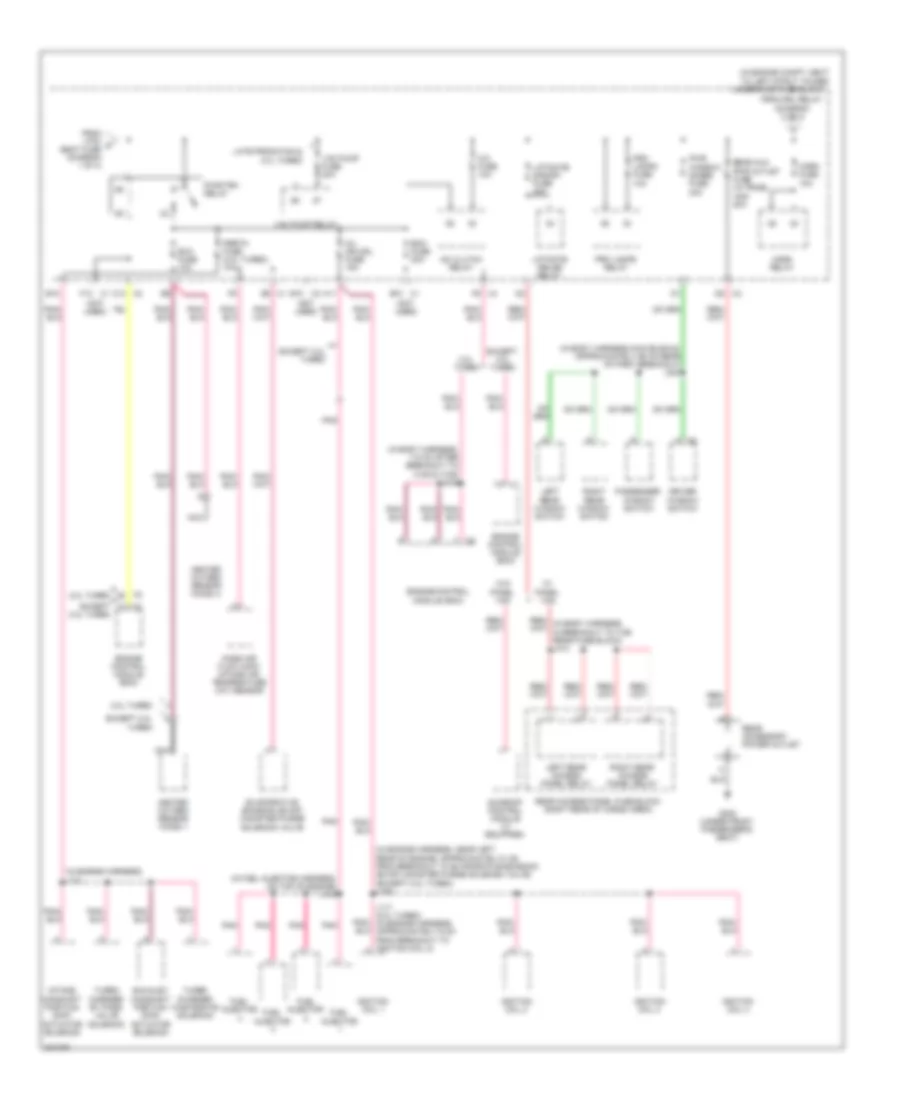
Power Distribution Wiring Diagram (3 of 4) for Chevrolet HHR SS 2009
List of elements for Power Distribution Wiring Diagram (3 of 4) for Chevrolet HHR SS 2009:
- (in body harness, approximately 10 cm from bcm breakout) j324
- (in i/p harness near ignition switch, approximately 4 cm from inflatable steering wheel coil module) j206
- (not used)
- (under center dash, below radio, on right side of center console) body control module (bcm)
- 10a
- 2.0l turbo
- A/t
- A8 x3
- Acc
- Air bag fuse 10a
- Alo
- Amp fuse 20a
- Asa
- Audio amplifier
- B provisional x406
- Chmsl relay
- Clstr fuse 10a
- D11
- D12 x3
- Driver information center (dic)
- Driver information center (dic) display
- Eps/str whl cntrl fuse 2a
- Except 2.0l turbo
- From underhood fuse block (diagram 1 of 4)
- Hvac control assembly
- Hvac/ ip ign fuse 10a
- Hvac/ pk3 + fuse 10a
- Ign sw/pk3 + fuse 2a
- Ignition lock cylinder control
- Ignition switch
- Inflatable restraint front passenger presence system (pps) module
- Inflatable restraint i/p module
- Inflatable restraint sensing & diagnostic module (sdm)
- Inflatable restraint steering wheel module coil
- Inflatable restraint vehicle rollover sensor
- Inside rearview mirror
- Instrument panel cluster (ipc)
- J327
- Key-in ignition switch
- Left steering wheel control switch
- Logic
- M/t
- Nca
- Off
- Pnk
- Power steering control module (pscm)
- Provisional fuse holder
- Rear view camera
- Run
- Start
- Stop lp fuse 10a
- Theft deterrent module (tdm)
- Theft deterrent module (tdm) actuator
- Turbo charger boost gage
- Underhood fuse block (diagram 1 of 4)
- Underhood relay block
- W/ enhanced audio speaker system
- W/ mulitiple information display
- W/ panel van
- W/ rear- view camera
- W/ rearview mirror
- W/ roof
- W/o rear- view camera
- W/o roof
- Windshield wiper/ washer switch
- Wpr fuse 10a
- X1 c
- X2 c
- X3 a6
- X4 d3
- X4 e6
- X4 f5
Power Distribution Wiring Diagram (4 of 4) for Chevrolet HHR SS 2009
List of elements for Power Distribution Wiring Diagram (4 of 4) for Chevrolet HHR SS 2009:
- (in body harness main bundle, approximately 65 cm rear of first breakout) j323
- (in body harness, 7.5 cm after breakout to x105 & x109) j113
- (in engine compt, next to left strut tower)
- (in engine harness) j121
- (in engine harness, near left rear of engine, approximately 8 cm from breakout to evaporative emission (evap) canister purge solenoid valve) (except 2.0l turbo) j106
- (in fuel injector harness, on top of engine) j104
- (not used)
- 2.0l turbo
- A/c clutch relay
- A/c fuse 10a
- A11
- B10
- D5 x2
- Driver window switch
- Ecm fuse 20a
- Engine control module (ecm)
- Evaporative emission (evap) canister purge solenoid valve
- Except 2.0l turbo
- Exh fuse 10a
- Exhaust camshaft position (cmp) actuator solenoid
- From drl relay (diagram 2 of 4)
- From htd/ c seat fuse (diagram 1 of 4)
- Fuel injector
- G302 (under front passenger's seat)
- Heated oxygen sensor (ho2s) 1
- Heated oxygen sensor (ho2s) 2
- Horn fuse 10a
- Horn relay
- Ignition coil 1
- Ignition coil 2
- Ignition coil 3
- Ignition coil 4
- Inj ign mdl fuse 15a
- Intake camshaft position (cmp) actuator solenoid
- J117 (2.0l turbo) (in engine harness, approximately 6 cm from breakout to ignition coil 2)
- Late prodution & 2.0l turbo
- Left rear access panel relay
- Left rear window switch
- Liftgate relse relay
- Liftgate/ s/roof/ fuse 20a
- Mass air flow (maf)/ intake air temperature (iat) sensor
- Nca
- Passenger window switch
- Pertn fuse (2.0l turbo) 10a
- Pnk
- Prk lamps fuse 10a
- Prk lamps relay
- Pwr window/ doors fuse 30a
- Pwr/trn relay
- Rear access panel fuse block (right rear of cargo area)
- Rear accessory power outlet
- Rear aux pwr outlet fuse (w/ panel van) 20a
- Right rear access panel relay
- Right rear window switch
- Sunroof control module (if equipped)
- Turbo charger by pass valve solenoid
- Turbo charger wastegate solenoid
- Underhood fuse block
- Vac pump fuse 20a
- Vac pump relay
- W/ panel van
- W/o panel van
- X1 b12
- X1 d9
- X1 f12
- X2 b10
- X2 c12
- X2 h
- X4 f6