POWER DISTRIBUTION
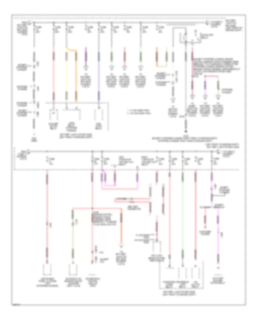
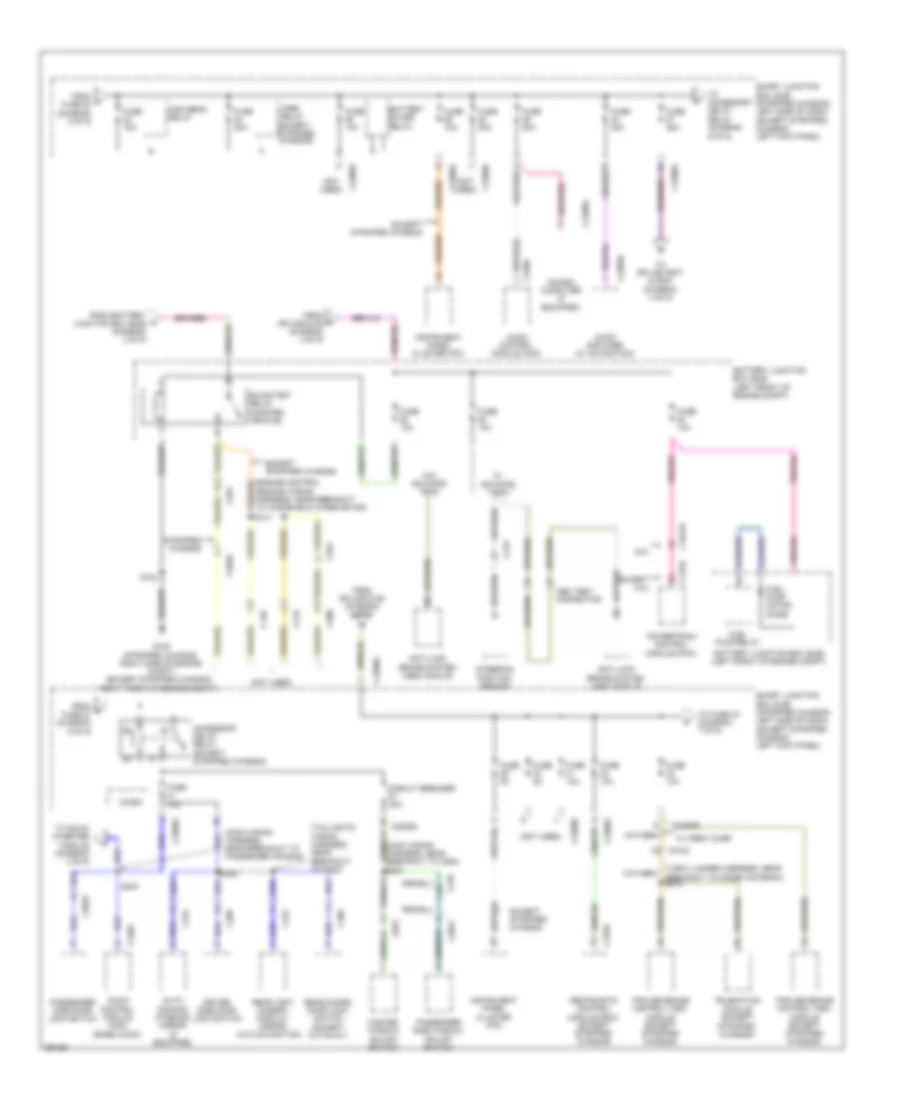
Power Distribution Wiring Diagram (1 of 9) for Ford E-150 XLT 2013

List of elements for Power Distribution Wiring Diagram (1 of 9) for Ford E-150 XLT 2013:
- (engine control red
- (engine control sensor wiring harness, in breakout to battery)
- (engine control sensor wiring harness, near breakout to battery junction box (bjb))
- (left front of engine compt)
- (right rear of engine)
- Battery
- Battery junction box (bjb)
- Battery secondary
- C1035a
- C1035b
- Except stripped chassis
- Fusible link j (8 ga- red)
- G109 (right front of engine compt)
- G120
- G121 (w/ dual battery) (front right side frame rail)
- G300 (w/o aft axle tank) (right underbody of vehicle)
- G400 (w/ aft axle tank) (right rear underbody of vehicle)
- Generator
- Red
- S106
- S107
- S113
- S114 (engine control sensor wiring harness, near breakout to battery junction box (bjb))
- S303
- S313 (w/o aft axle tank) s413 (w/ aft axle tank)
- Sensor wiring harness, in breakout to battery)
- Starter motor
- Stripped chassis
- To fuse 15 (diagram 2 of 9)
- To smart junction box (sjb) (diagram 3 of 9)
- W/ dual battery
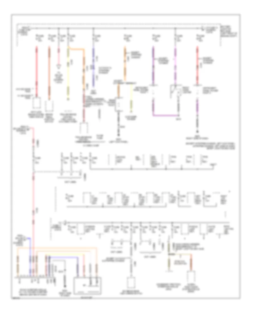
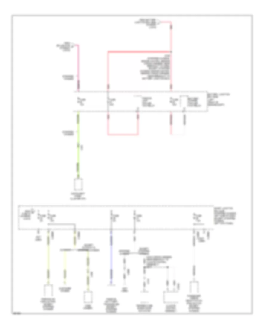
Power Distribution Wiring Diagram (2 of 9) for Ford E-150 XLT 2013
List of elements for Power Distribution Wiring Diagram (2 of 9) for Ford E-150 XLT 2013:
- (except stripped chassis: engine control sensor wiring harness, near breakout to windshield wiper motor) (stripped chassis: engine control sensor wiring harness, near breakout to anti-lock brake system (abs) module) s136
- (except stripped chassis: right front of engine compt) (stripped chassis: right side of engine compt)
- (left front of engine compt) battery junction box (bjb)
- (not used)
- 6.8l
- A/c clutch relay
- Abs test connector
- Anti-lock brake system (abs) module
- Auxiliary blower motor relay
- Battery junction box (bjb) (left front of engine compt)
- Blower motor relay
- C110
- C1551b
- C175b
- C2026
- C219
- C264
- C291
- C300
- C405
- Customer access
- Cutaway
- Evaporative emission (evap) canister vent valve
- Except
- Except 6.8l
- Except cutaway
- Except stripped chassis
- From a battery junction box (bjb) (diagram 1 of 9)
- From c fuse 14 (diagram 2 of 9)
- Fuel pump relay
- Fuse 10a
- Fuse 15a
- Fuse 20a
- Fuse 30a
- Fuse 40a
- Fuse 50a
- G100
- Horn relay (stripped chassis)
- Instrument panel cluster (ipc) (stripped chassis)
- Left turn/stop trailer tow relay
- Powertrain control module (pcm)
- Red
- Reversing lamp relay
- Right turn/stop trailer tow relay
- Run/start relay
- S108
- S129 (engine control sensor wiring harness, near breakout to brake fluid level switch)
- Stripped chassis
- To battery junction box (bjb) (diagram 6 of 9)
- To battery junction box (bjb) (diagram 7 of 9)
- To battery junction box (bjb) (diagram 8 of 9)
- To battery junction box (bjb) (diagram 9 of 9)
- To fuse 31 (diagram 2 of 9)
- To fuse 33 (diagram 3 of 9)
- To ignition switch (diagram 4 of 9)
- To smart junction box (sjb) (diagram 6 of 9)
- W/ advance trac
- W/ advance trac w/o advance trac
- W/o advance trac
- Windshield wiper relay
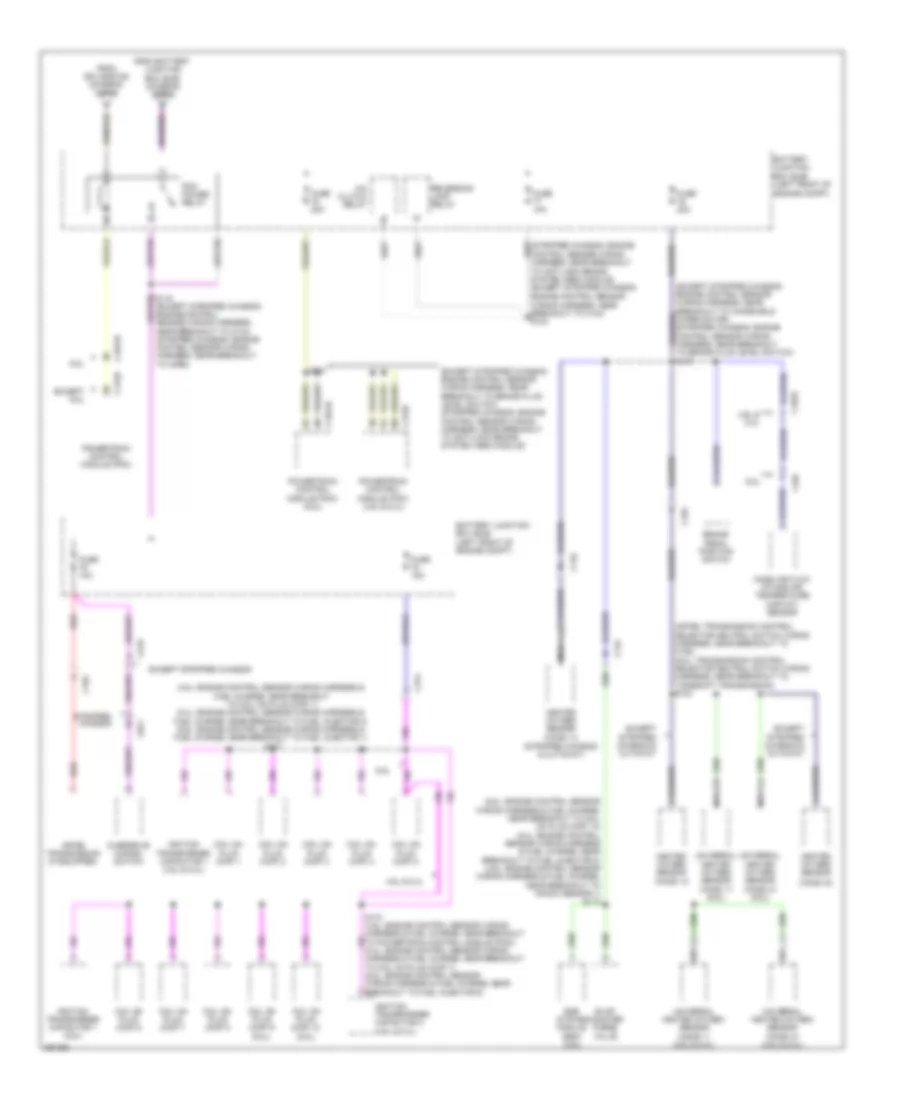
Power Distribution Wiring Diagram (3 of 9) for Ford E-150 XLT 2013
List of elements for Power Distribution Wiring Diagram (3 of 9) for Ford E-150 XLT 2013:
- & stripped chassis
- (apim)
- (except stripped chassis: left kick panel) (stripped chassis: left side of dash) smart junction box (sjb)
- (gpsm)
- (main wiring harness, near breakout to smart junction box (sjb)
- (not used)
- (t-box jumper harness, near breakout to modem antenna) s272
- 3rd row seat enable (fet)
- Ac outlet
- Ac-a
- Ac-b
- Acc
- Accessory protocol
- Anti-lock brake system (abs) module
- Back lighting led (fet)
- Battery junction box (bjb) (left front of engine compt)
- Brake pedal position switch
- Bsi (fet)
- C110
- C210
- C2108
- C219
- C2280a
- C2280b
- C2280d
- C2280g
- C263
- C268
- C432
- Cbp41
- Customer access
- Cutaway
- Cutaway & stripped chassis
- Dc/ac inverter module (w/ 110v power inverter) (behind center of dash)
- Except cutaway
- Except stripped chassis
- Exterior rear view mirror switch
- Floor lamp (fet)
- From d fuse 16 (diagram 2 of 9)
- From splice f s200 (diagram 6 of 9)
- From splice s114 b (diagram 1 of 9)
- Front cigar lighter
- Fuse 10a
- Fuse 15a
- Fuse 20a
- Fuse 30a
- Fuse 40a
- Fuse 50a
- Fuse 5a
- Fuse 7.5a
- G200 (right side of dash)
- G203 (left kick panel)
- Gd116
- Global
- Gnd
- Hot
- Hya01
- Hya02
- Inline fuse
- Instrument panel power point 1
- Instrument panel power point 2
- Interface module
- Interior lighting (fet)
- Keypad illmu (fet)
- Led+
- Led-
- Left low beam (fet)
- Lf turn lamp (fet)
- Lr stop/ turn lamp (fet)
- Lr turn lamp (fet)
- Lya03
- Neut
- Positioning
- Puddle lamp (fet)
- Rear power point
- Red
- Rf turn lamp (fet)
- Right low beam (fet)
- Rr stop/ turn lamp (fet)
- Rr turn lamp (fet)
- Rya03
- S218
- S240
- S268
- Sbp01
- Sync w/o navigation
- System module
- To fuse 17 (diagram 5 of 9)
- To fuse 74 (diagram 4 of 9)
- To splice s159 (diagram 7 of 9)
- Tpms (fet)
- Trailer brake control (tbc) module
- Trailer brake control (tbc) module (w/o crew chief)
- Vbatt
- W/ advance trac
- W/ crew chief
- W/o advance trac
- White light (fet)
Power Distribution Wiring Diagram (4 of 9) for Ford E-150 XLT 2013
List of elements for Power Distribution Wiring Diagram (4 of 9) for Ford E-150 XLT 2013:
- (engine control sensor wiring harness, near breakout to windshield wiper motor) s143
- (main wiring harness, near breakout to g202) (except stripped chassis) s227
- (main wiring harness, near breakout to ignition switch) (stripped chassis) s244
- (not used)
- (stripped chassis)
- Acc
- Battery charge trailer tow relay
- Battery junction box (bjb) (left front of engine compt)
- C1348
- C140
- C2095
- C215
- C2280a
- C2280b
- C2280d
- C2280e
- C264
- C291
- C300
- C3133
- Data link connector (dlc)
- Driver side front seat control switch
- Except stripped chassis
- From battery junction box (bjb) (diagram 2 of 9)
- From e fuse 65 (diagram 3 of 9)
- From smart junction box (sjb) (diagram 6 of 9)
- Fuse 10a
- Fuse 15a
- Fuse 20a
- Fuse 30a
- Fuse 50a
- Fuse 5a
- Ignition switch
- Lock
- Off
- Run
- Run/ acc ign sw
- Run/start ign sw
- Smart junction box (sjb) (stripped chassis: left side of dash) (except stripped chassis: left kick panel)
- Start
- Starter relay
- Stripped chassis
- To battery junction box (bjb) (diagram 9 of 9)
- To splice s132 & battery junction box (bjb) (diagram 5 of 9)
- To upfitter switch (diagram 9 of 9)
- Windshield wiper motor
- Windshield wiper relay
Power Distribution Wiring Diagram (5 of 9) for Ford E-150 XLT 2013
List of elements for Power Distribution Wiring Diagram (5 of 9) for Ford E-150 XLT 2013:
- (engine control sensor wiring harness, near breakout to anti-lock brake system (abs) module) s139
- (engine control sensor wiring harness, near breakout to windshield wiper motor) s139
- (not used)
- 6.8l
- Audio control module (acm) (except stripped chassis)
- Battery junction box (bjb) (left front of engine compt)
- C1551b
- C175b
- C192
- C219
- C2280a
- C2280b
- C2280d
- C2408a
- C240a
- C291
- Data link connector (dlc)
- Digital transmission range (dtr) sensor (w/ 4r75e)
- Door lock relay
- Driver door unlock relay
- Except 6.8l
- Except stripped chassis
- Fog lamp relay
- From h fuse 9 (diagram 3 of 9)
- From ignition switch l (diagram 4 of 9)
- Fuse 15a
- Fuse 20a
- Fuse 25a
- Fuse 5a
- In-dash computer (if equipped)
- Lh corner lamp (fet)
- Liftgate glass release relay
- Liftgate rel (fet)
- Park lamp relay
- Powertrain control module (pcm)
- Pulse train (fet)
- Rh corner lamp (fet)
- S132 (engine control sensor wiring harness, near breakout to brake fluid level switch)
- Smart junction box (sjb) (stripped chassis: left side of dash) (except stripped chassis: left kick panel)
- Start diode
- Starter relay
- Stripped chassis
- To fuse (diagram 6 of 9)
- W/ torqshift
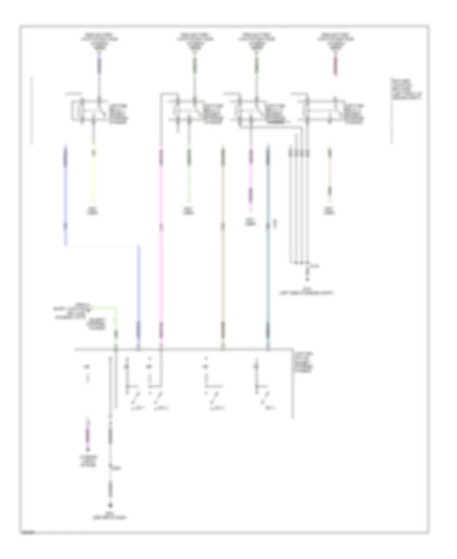
Power Distribution Wiring Diagram (6 of 9) for Ford E-150 XLT 2013
List of elements for Power Distribution Wiring Diagram (6 of 9) for Ford E-150 XLT 2013:
- (engine control sensor wiring harness, near breakout to windshield wiper motor)
- (except stripped chassis)
- (main wiring harness, near breakout to c264) s234
- (main wiring harness, near breakout to passenger air bag)
- (not used)
- (t-box jumper harness, near breakout to modem antenna) s274
- (taillights wiring harness, near breakout to c263)
- 6.8l
- Abs test connector
- Accessory delay relay (except stripped chassis)
- Anti-lock brake system (abs) module
- Audio amplifier (w/ navigation)
- Audio control module (acm)
- Audio control module (acm) (base audio)
- Auto- dimming interior mirror (if equipped)
- Battery junction box (bjb) (left front of engine compt)
- Battery saver relay
- C140
- C1551b
- C175b
- C2026
- C210
- C2108
- C215
- C219
- C2280a
- C2280b
- C2280d
- C2280e
- C2385b
- C2408a
- C240a
- C264
- C265
- C268
- C291
- C300
- C3047
- C3049
- C310a
- C315
- C406
- Circuit breaker 30a
- Driver side door lock switch
- Except 6.8l
- Except stripped chassis
- From battery n junction box (bjb) (diagram 2 of 9)
- From fuse 27 (diagram 6 of 9)
- From j fuse 22 (diagram 5 of 9)
- From r splice s136 (diagram 2 of 9)
- From splice s136 (diagram 2 of 9)
- Fuel pump motor diode
- Fuel pump relay
- Fuse 10a
- Fuse 15a
- Fuse 20a
- Fuse 5a
- G100 (stripped chassis: right side of engine compt) (except stripped chassis: right front of engine compt)
- High beam relay
- Horn relay
- In-dash computer (if equipped)
- Instrument panel cluster (ipc)
- Master window adjust switch
- Micro
- Passenger side door lock switch
- Passenger side window adjust switch
- Powertrain control module (pcm)
- Rear doors door lock switch (except cutaway)
- Rear view camera display mirror (w/o navigation)
- Restraints control module (rcm) (except stripped chassis)
- Run/start relay (modified vehicle)
- S108
- S200
- S236
- Smart junction box (sjb) (stripped chassis: left side of dash) (except stripped chassis: left kick panel)
- Steering position sensor
- Stripped chassis
- Telematics module (except stripped chassis)
- To accessory delay relay (diagram 6 of 9)
- To dc/ac inverter module (diagram 3 of 9)
- To fuse 34 (diagram 7 of 9)
- To splice s227 & s244 (diagram 4 of 9)
- Trailer brake control (tbc) module (except stripped chassis)
- W/ advance trac
- W/ crew chief
- W/o advance trac
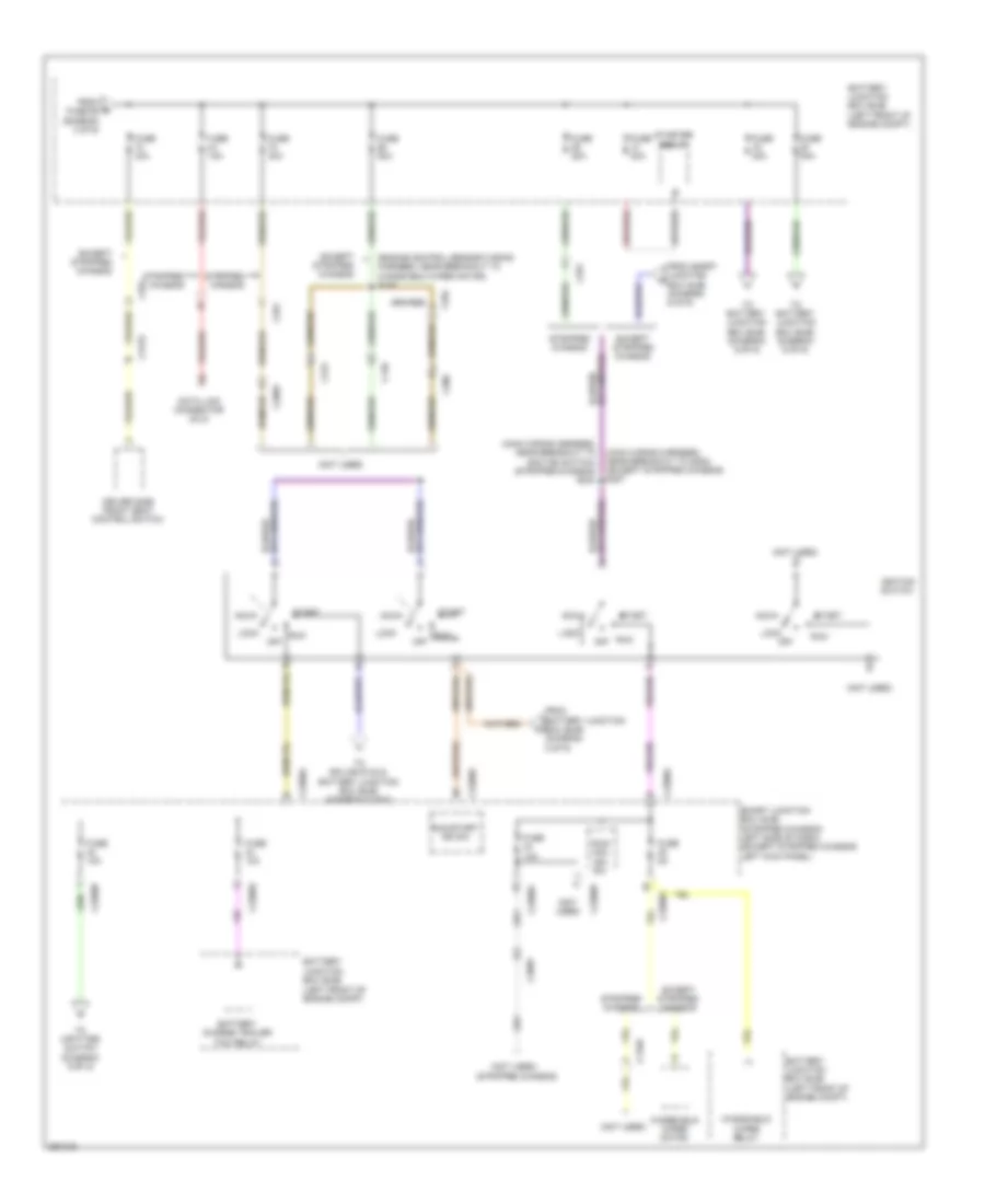
Power Distribution Wiring Diagram (7 of 9) for Ford E-150 XLT 2013
List of elements for Power Distribution Wiring Diagram (7 of 9) for Ford E-150 XLT 2013:
- (left
- (main wiring harness, near breakout to climate control assembly) s217
- (not used)
- Battery charge trailer tow relay
- Battery junction box (bjb)
- C2095
- C214
- C2280b
- C2280d
- C291
- C294a
- C406
- Climate control assembly
- Customer access
- Cutaway
- Except cutaway & stripped chassis
- Except stripped chassis
- From battery junction box (bjb) u (diagram 3 of 9)
- From q fuse 33 (diagram 6 of 9)
- From splice s136 s (diagram 2 of 9)
- Front of engine compt)
- Fuse 10a
- Fuse 20a
- Fuse 30a
- Fuse 5a
- Fuse 7.5a
- Instrument panel cluster (ipc)
- Parking aid module (pam) (except stripped chassis)
- Parking lamp trailer tow relay
- Passenger airbag deactivation (pad) switch (except stripped chassis)
- Passive anti-theft transceiver (except stripped chassis)
- Red
- S159 (stripped chassis: engine control sensor wiring harness, near breakout to horn) (except stripped chassis: engine control sensor wiring harness, near breakout to battery junction box)
- Smart junction box (sjb) (stripped chassis: left side of dash) (except stripped chassis: left kick panel)
- Stripped chassis
- Temperature blend door actuator
- Video camera
Power Distribution Wiring Diagram (8 of 9) for Ford E-150 XLT 2013
List of elements for Power Distribution Wiring Diagram (8 of 9) for Ford E-150 XLT 2013:
- (4.6l: engine control sensor wiring harness & fuel charge, near breakout to coil on plug (cop) 1) (5.4l: engine control sensor wiring harness & fuel charge, near breakout to fuel injector 2) (6.8l: engine control sensor wiring harness & fuel charge, near breakout to fuel injector 1) s177
- (4r75e: transmission control selector neutral switch wiring harness, near breakout to c192) (6.8l: transmission control selector neutral switch wiring harness, near breakout to torqshift transmission) s103
- (6.8l: engine control sensor wiring harness & fuel charge, near breakout to coil on plug (cop) 10) (5.4l: engine control sensor wiring harness & fuel charge, near breakout to fuel injector 8) (4.6l: engine control sensor wiring harness & fuel charge, near breakout to knock sensor 1) s174
- (except stripped chassis: engine control sensor wiring harness, near breakout to brake fluid level switch) (stripped chassis: engine control sensor wiring harness, near breakout to anti-lock brake system (abs) module)
- (ho2s) 12 (stripped chassis & cutaway)
- (ho2s) 22
- 4.6l & 5.4l
- 4r75e transmission (if equipped)
- 6.8l
- A/c clutch relay
- Battery junction box (bjb) (left front of engine compt)
- Brake pedal position switch
- C1033
- C110
- C134
- C139
- C1551b
- C175b
- C192
- C219
- C291
- C314
- Coil on plug (cop) 1
- Coil on plug (cop) 10 (6.8l)
- Coil on plug (cop) 2
- Coil on plug (cop) 3
- Coil on plug (cop) 4
- Coil on plug (cop) 5
- Coil on plug (cop) 6
- Coil on plug (cop) 7
- Coil on plug (cop) 8
- Coil on plug (cop) 9 (6.8l)
- Control sensor wiring harness, near breakout to anti-lock brake system (abs) module) (except stripped chassis:
- Egr system module (esm) (4.6l)
- Engine control sensor wiring harness, near breakout to c134) s124
- Evap canister purge valve
- Except 6.8l
- Except stripped chassis
- Except stripped chassis & cutaway
- From battery junction box (bjb) (diagram 2 of 9)
- From splice s129 (diagram 2 of 9)
- Fuse 10a
- Fuse 15a
- Fuse 20a
- Harness & fuel charge, near breakout to coil on plug (cop) 7) (6.8l: engine control sensor wiring harness & fuel charge, near breakout to fuel injector 6)
- Heated oxygen sensor
- Heated oxygen sensor (ho2s) 12
- Ignition transformer capacitor 1 (4.6l & 5.4l)
- Ignition transformer capacitor 1 (6.8l)
- Ignition transformer capacitor 2 (4.6l & 5.4l)
- Mass air flow intake air temperature (maf/iat) sensor
- Nca
- Overdrive cancel switch
- Pcm power relay
- Powertrain control module (pcm)
- Powertrain control module (pcm) (4.6l & 5.4l)
- Powertrain control module (pcm) (6.8l)
- Red
- Reversing lamp relay
- S131
- Stripped chassis
- To brake fluid level switch) s137
- Universal heated oxygen sensor (ho2s) 11 (4.6l & 5.4l)
- Universal heated oxygen sensor (ho2s) 11 (6.8l)
- Universal heated oxygen sensor (ho2s) 21 (4.6l & 5.4l)
- Universal heated oxygen sensor (ho2s) 21 (6.8l)
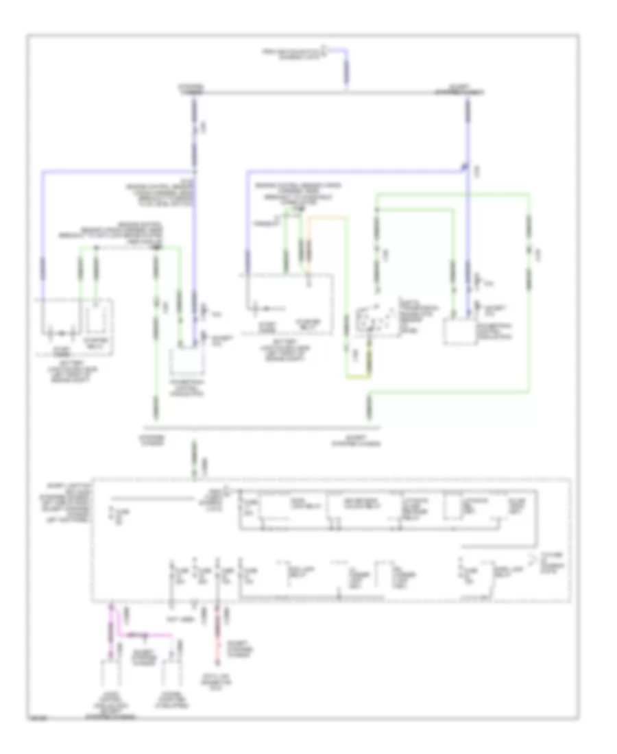
Power Distribution Wiring Diagram (9 of 9) for Ford E-150 XLT 2013
List of elements for Power Distribution Wiring Diagram (9 of 9) for Ford E-150 XLT 2013:
- (not used)
- Battery junction box (bjb) (left front of engine compt)
- C219
- Except stripped chassis
- From battery junction box (bjb) (diagram 2 of 9)
- From battery junction box (bjb) (diagram 4 of 9)
- From smart junction g box (sjb) (diagram 4 of 9)
- G101 (left side of engine compt)
- G201 (center of dash)
- Interior lights system
- S123
- S264
- Sw 1
- Sw 2
- Sw 3
- Sw 4
- Upfitter relay 1 (except stripped chassis)
- Upfitter relay 2 (except stripped chassis)
- Upfitter relay 3 (except stripped chassis)
- Upfitter relay 4 (except stripped chassis)
- Upfitter switch (except stripped chassis)