POWER DISTRIBUTION
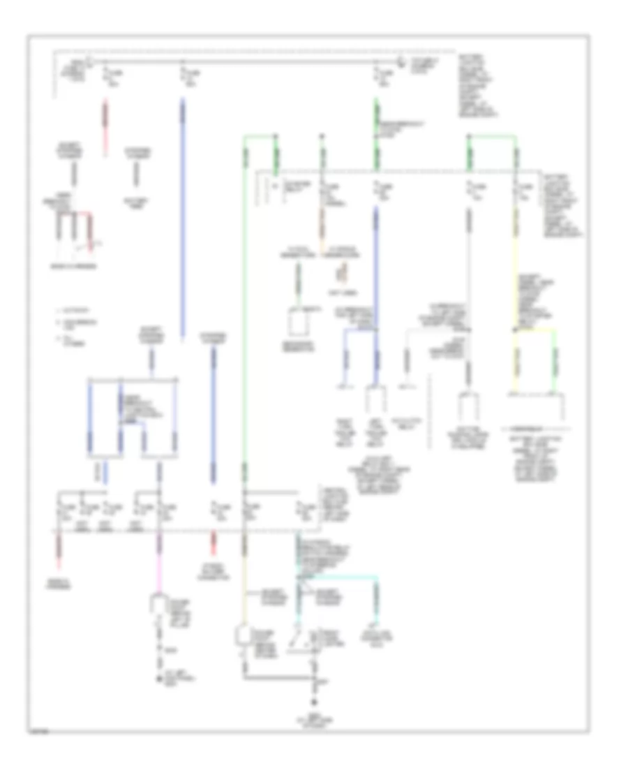
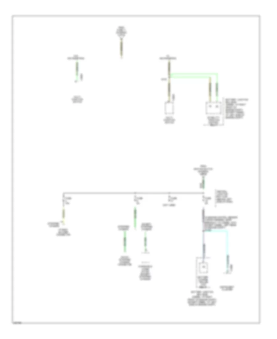
Power Distribution Wiring Diagram (1 of 6) for Ford E450 Super Duty 2006

List of elements for Power Distribution Wiring Diagram (1 of 6) for Ford E450 Super Duty 2006:
- (diesel: at right rear of engine compt) (except diesel: at left side of engine compt) battery junction box (bjb)
- (in alternator rectifier system wiring harness, near breakout to top left rear of engine) s1076
- (in breakout to right side of engine compt) s1007
- (in starter relay/battery wiring harness, in breakout to left side of engine compt) s1074
- (near breakout to left front of engine) s1054
- (near breakout to right side of engine) s1051
- (near breakout to right side of engine) s1072
- (near breakout to top left rear of engine) red s1075
- (near breakout to top left rear of engine) s1073
- Battery
- Battery ii
- Battery junction box (bjb) (diesel: at right front of engine compt) (except diesel: at left side of engine compt)
- Blower motor relay
- C102a
- C102c
- C1251b
- C1301a
- C1301b
- Diesel
- Except diesel
- Fuel injector control module (ficm) power relay
- Fuel pump relay
- Fuse 20a
- Fuse 50a
- Generator
- Glow plug control module (gpcm)
- Nca
- Red
- Remote jump start terminal
- S1008 (in breakout to right side of engine compt)
- S1052 (near breakout to front of engine)
- S1055 (near breakout to left front of engine)
- S1056 (near breakout to left front of engine)
- S1071 (near breakout to right side of engine)
- S1073 (near breakout to top left rear of engine) red
- S191 (in breakout to left side of engine compt)
- S192 (in breakout to left side of engine compt)
- Secondary generator
- Starter motor
- To fuse 9 (diagram 2 of 5)
- To fuse 9 (diagram 2 of 6)
- W/ dual generators
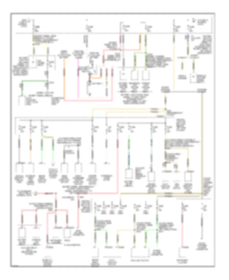
Power Distribution Wiring Diagram (2 of 6) for Ford E450 Super Duty 2006
List of elements for Power Distribution Wiring Diagram (2 of 6) for Ford E450 Super Duty 2006:
- (at breakout for left side of dash) s1019
- (at left kick panel) g204
- (except diesel: near breakout to g105) (diesel: near breakout to starter relay) s1034
- (except stripped chassis)
- (in breakout to left side of engine compt) (except diesel) s186
- (in window regulator relay switch harness, near breakout to steering column) s229
- (near breakout to central junction box) s266
- (near breakout to g105) s1028
- (near breakout to g105) s2012
- (not used)
- A/c clutch relay
- All
- Auxiliary relay box 1 (diesel: at right rear of engine compt) (except diesel: at left rear of engine compt)
- Battery feed
- Battery junction box (bjb) (diesel: at right front of engine compt) (except diesel: at left side of engine compt)
- C1251a
- Central junction box (cjb) (behind left side of dash)
- Conversion
- Cutaway
- Data link connector (dlc)
- Daytime running lamps (drl) module (if equipped)
- Ends in harness
- Except stripped chassis
- From a fuse 13 (diagram 1 of 6)
- Front cigar lighter
- Fuse
- Fuse 10a
- Fuse 10a (diesel)
- Fuse 15a
- Fuse 20a
- Fuse 30a
- Fuse 50a
- Fuse 60a
- G202 (at left side of dash)
- Horn relay
- I/p body builder connector
- Left turn trailer tow relay
- Others
- Power point (behind center of dash)
- Power point (behind left "b" pillar)
- Red
- Right turn trailer tow relay
- S145 (diesel) (near break- out to g107)
- S207
- S235
- Secondary generator
- Starter relay
- Stripped chassis
- To fuse 21 (diagram 3 of 6)
- Van
- W/ dual generators
- W/ single generators
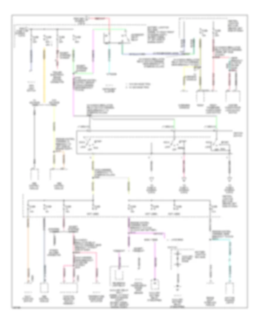
Power Distribution Wiring Diagram (3 of 6) for Ford E450 Super Duty 2006
List of elements for Power Distribution Wiring Diagram (3 of 6) for Ford E450 Super Duty 2006:
- (diesel)
- (except diesel)
- (except diesel: near breakout to g105)
- (except diesel: near breakout to g105) (diesel: near breakout to starter relay) s1033
- (except diesel: near breakout to right side of dash) (diesel: near breakout to left side of dash)
- (in main wiring harness, in breakout to c219)
- (in main wiring harness, near breakout to c219) s282
- (in main wiring harness, near breakout to center of dash) s205
- (in main wiring harness, near breakout to left side of dash) s219
- (in main wiring harness, near breakout to left side of dash) s221
- (in main wiring harness, under left side of dash) s276
- (in window regulator relay switch harness, near breakout to c248)
- (in window regulator relay switch harness, near breakout to right side of dash) (w/ remote keyless entry) s261
- (not used)
- 16-way stripped chassis connector
- Auxiliary battery relay
- Auxiliary relay box 2 (behind center of dash)
- Battery charge trailer tow relay
- Battery ii
- Battery junction box (bjb) (diesel: at right front of engine compt) (except diesel: at left side of engine compt)
- Battery saver relay
- Body builder connector
- Brake pedal position switch
- C.b. 20a
- C175
- C176a
- C202a
- C202b
- C2035
- C203a
- C2188a
- C220b
- Central junction box (cjb) (behind left side of dash)
- Conversion van
- Cutaway
- Diesel and all w/o auxiliary battery
- Driver side front seat adjust switch
- Ends in harness
- Evap canister vent valve (gas)
- Except cutaway
- Except stripped chassis
- Exterior rear view mirror switch
- From b fuse 18 (diagram 2 of 6)
- Front passenger window/ door lock switch
- Fuse
- Fuse 10a
- Fuse 15a
- Fuse 20a
- Fuse 30a
- Fuse 40a
- Fuse 50a
- Fuse 5a
- Fuse 60a
- Fuse fuse 30a 30a
- Gasoline w/ auxiliary battery
- Gasoline w/ auxiliary battery jumper
- I/p body builder connector
- Instrument cluster
- Interior lamp relay
- Main light switch
- Master window/ door lock/ unlock switch
- Multi- function switch
- Nca
- Parking lamp trailer tow relay
- Pcm power relay
- Powertrain control module (pcm)
- Radio
- Rear a/c blower speed relay 1
- Rear doors door lock switch
- Red
- Reversing lamp trailer tow relay
- S1021
- S1027 (diesel: near breakout to starter relay)
- S1032 (diesel: in engine control sensor wiring harness, near breakout to starter relay) (except diesel: near breakout to g105)
- S218
- S225 (near breakout to c237)
- S237
- S291
- Stability/ traction control switch
- Stripped chassis
- To accessory delay relay (diagram 4 of 6)
- To fuse 15 (diagram 4 of 6)
- To multi- function switch (diagram 6 of 6)
- Vehicle security module (vsm)
- Vehicle security module (vsm) (w/ rke)
- W/ advancetrac
- W/ auxiliary a/c
- Windshield wiper motor
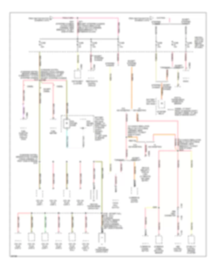
Power Distribution Wiring Diagram (4 of 6) for Ford E450 Super Duty 2006
List of elements for Power Distribution Wiring Diagram (4 of 6) for Ford E450 Super Duty 2006:
- (engine control harness, in breakout to left side of engine compt) s177
- (engine control harness, near breakout to c134) (w/ auxiliary battery) s113
- (engine control harness, near breakout to c219) s2013
- (in window regulator relay switch harness, near breakout to c237) s245
- (in window regulator relay switch harness, near breakout to right side of dash) s242
- (in window regulator relay switch harness, near breakout to steering column)
- (in window regulator relay switch harness, near breakout to steering column) s230
- (in window regulator relay switch harness, under left side of dash) s236
- (main harness, in breakout to steering column) s280
- (main harness, near breakout to center of dash) s203
- (near breakout in top of driver door) s501
- (not used)
- 40a
- Abs control module
- Acc
- Accessory delay relay
- Auxiliary battery diode
- Auxiliary battery relay (if equipped)
- Auxiliary relay box 1 (diesel: at right rear of engine compt) (except diesel: at left rear of engine compt)
- Battery junction box (bjb)
- Battery junction box (bjb) (diesel: at right front of engine compt) (except diesel: at left side of engine compt)
- Brake shift interlock module
- C202a
- C2188a
- C220b
- C294a
- Central junction box (cjb) (behind left side of dash)
- Daytime running lights
- Digital transmission range (dtr) sensor
- Early prod
- Except stripped chassis
- Except torqshift
- From e fuse 14 (diagram 3 of 6)
- From s291 f (diagram 3 of 6)
- Front passenger window/door lock switch
- Function selector switch assembly
- Fuse
- Fuse 10a
- Fuse 15a
- Fuse 20a
- Fuse 30a
- Fuse 5a
- Fuse 60a
- I/p body builder connector
- Ignition switch
- Instrument cluster
- Late prod
- Lock
- Main light switch
- Master window/door lock/unlock switch
- Multi- function switch
- Nca
- Off
- Overhead console
- Radio
- Red
- Reversing lamp relay
- Run
- S227
- Start
- Stripped chassis
- Temperature blend door actuator
- To fuse 14 (diagram 5 of 6)
- To fuse 33 (diagram 5 of 6)
- To fuse 9 (diagram 5 of 6)
- Torqshift
- Trailer electronic brake control connector
- W/ advance trac
- W/ overhead console
- W/ power door locks
- W/o advance trac
Power Distribution Wiring Diagram (5 of 6) for Ford E450 Super Duty 2006
List of elements for Power Distribution Wiring Diagram (5 of 6) for Ford E450 Super Duty 2006:
- (6.8l)
- (diesel: at right front of engine compt) (except diesel: at left side of engine compt)
- (except 6.8l)
- (in engine control sensor & fuel charge wiring harness, at right side of engine) s161
- (in engine control sensor harness, in breakout to c219) (stripped chassis) s127
- (in engine control sensor wiring harness, near breakout to left rear of engine compt) (except stripped chassis) s1065
- (in window regulator relay switch wiring harness, near breakout to right side of dash) s216
- (w/ remote keyless entry)
- Abs
- Battery junction box (bjb)
- Battery junction box (bjb) (diesel: at right front of engine compt) (except diesel: at left side of engine compt)
- C126
- C1388c
- C149
- C203b
- C2188a
- C220a
- C310a
- Cancel switch
- Central junction box (cjb) (behind left side of dash)
- Coil on plug (cop) 1
- Coil on plug (cop) 10 (6.8l)
- Coil on plug (cop) 2
- Coil on plug (cop) 3
- Coil on plug (cop) 4
- Coil on plug (cop) 5
- Coil on plug (cop) 6
- Coil on plug (cop) 7
- Coil on plug (cop) 8
- Coil on plug (cop) 9 (6.8l)
- Control module
- Control sensor cluster
- Diesel
- Digital transmission range (dtr) sensor
- Except diesel
- Except stripped chassis
- Except torqshift
- From ignition switch k (diagram 4 of 6)
- From ignition switch l (diagram 4 of 6)
- Fuel heater
- Fuel injector control module (ficm)
- Fuse 10a
- Fuse 30a
- Fuse 5a
- Haul switch
- Ignition transformer capacitor 1
- Ignition transformer capacitor 2
- Instrument cluster
- Nca
- Overdrive
- Pcm power diode
- Pcm power relay
- Radio
- Restraints control module
- S156
- S162 (in engine control sensor & fuel charge wiring harness, near breakout to left side of engine)
- S260
- S271 (except stripped chassis) (in window regulator relay switch harness, near breakout to steering column)
- S281 (stripped chassis) (in main wiring harness, near breakout to left side of dash)
- Security module (vsm)
- Stability
- Starter relay
- Steering
- Stripped chassis
- Tan/red
- Test connector
- Torqshift
- Town/
- Vehicle
- W/ advancetrac
- W/o advancetrac
- Wheel rotation sensor
Power Distribution Wiring Diagram (6 of 6) for Ford E450 Super Duty 2006
List of elements for Power Distribution Wiring Diagram (6 of 6) for Ford E450 Super Duty 2006:
- (in engine control sensor wiring harness, near breakout to: diesel: g107, except diesel: left rear of engine compt) s1022
- (not used)
- 16-way stripped chassis connector
- Battery charge trailer tow relay
- Battery junction box (bjb) (diesel: at right front of engine compt) (except diesel: at left side of engine compt)
- C202a
- C220b
- Central junction box (cjb) (behind left side of dash)
- Except stripped chassis
- From fuse 11 (diagram 3 of 6)
- From ignition switch (diagram 4 of 6)
- Fuse
- Fuse 15a
- Fuse 5a
- I/p body builder connector
- Instrument cluster
- Multi- function switch
- S105
- Stability/ traction control relay
- Stripped chassis
- W/ advancetrac
- W/o advancetrac
- Windshield wiper motor (except stripped chassis)