POWER DISTRIBUTION
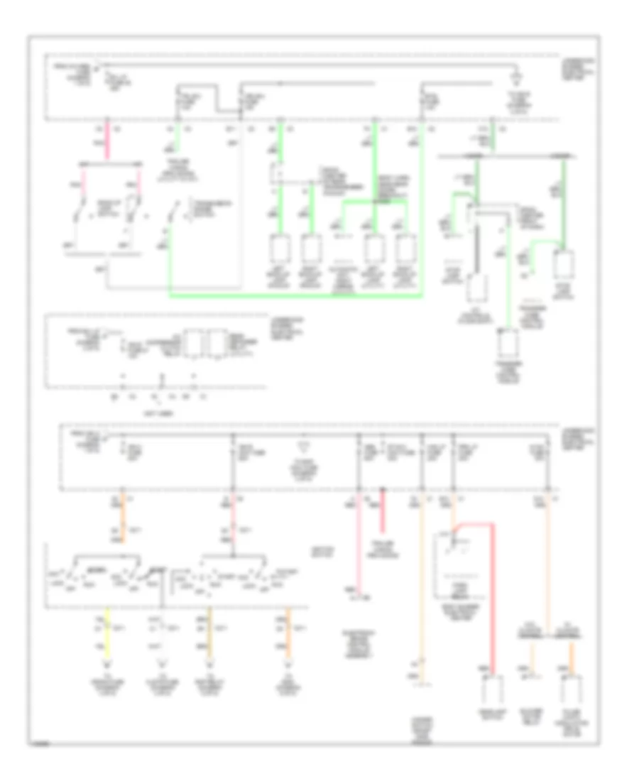
Power Distribution Wiring Diagram (1 of 5) for GMC Sonoma 1998

List of elements for Power Distribution Wiring Diagram (1 of 5) for GMC Sonoma 1998:
- (2.2l)
- (4.3l)
- A10
- Acc
- B10
- B11
- Battery
- Battery mega fuse 175a
- C10
- C211
- Camshaft position sensor (4.3l)
- Central sequential fuel injection (4.3l)
- Crankshaft position sensor (4.3l)
- D10
- E10
- Ecm 1 fuse 15 15a
- Electronic ignition control module
- Eng 1 fuse 10a
- Evaporative emission canister purge solenoid valve
- Evaporative emission canister vent solenoid valve
- F10
- From ecm 1 a fuse diagram 1 of 5)
- Fuel injectors
- Fusible link (10 ga-red)
- Gauges fuse 4 10a
- Generator
- Hazard switch (sport side pickup)
- I/p fuse block
- Ign a fuse 40a
- Ignition coil (4.3l)
- Ignition switch
- Inflatable restraint switch and diagnostic module
- Instrument cluster
- Left front heated oxygen sensor (4.3l)
- Lock
- Mass air flow sensor (4.3l)
- Off
- Oxygen fuse 20a
- Pickup
- Pnk
- Post converter heated oxygen sensor (4.3l)
- Powertrain control module (2.2l)
- Red
- Right front heated oxygen sensor (4.3l)
- Right inflatable restraint defeat switch and indicator
- Run
- S150 (heated oxygen sensor harn, pnk near heated oxygen sensor breakout)
- Sir fuse 16 15a
- Start
- Starter
- Starter relay
- To b/u lp fuse (diagram 2 of 5)
- To eng 1 fuse (diagram 1 of 5)
- To ign c fuse (diagram 2 of 5)
- Truck body control module
- Turn fuse 10 20a
- Underhood bussed electrical center
- Vehicle control module (4.3l)
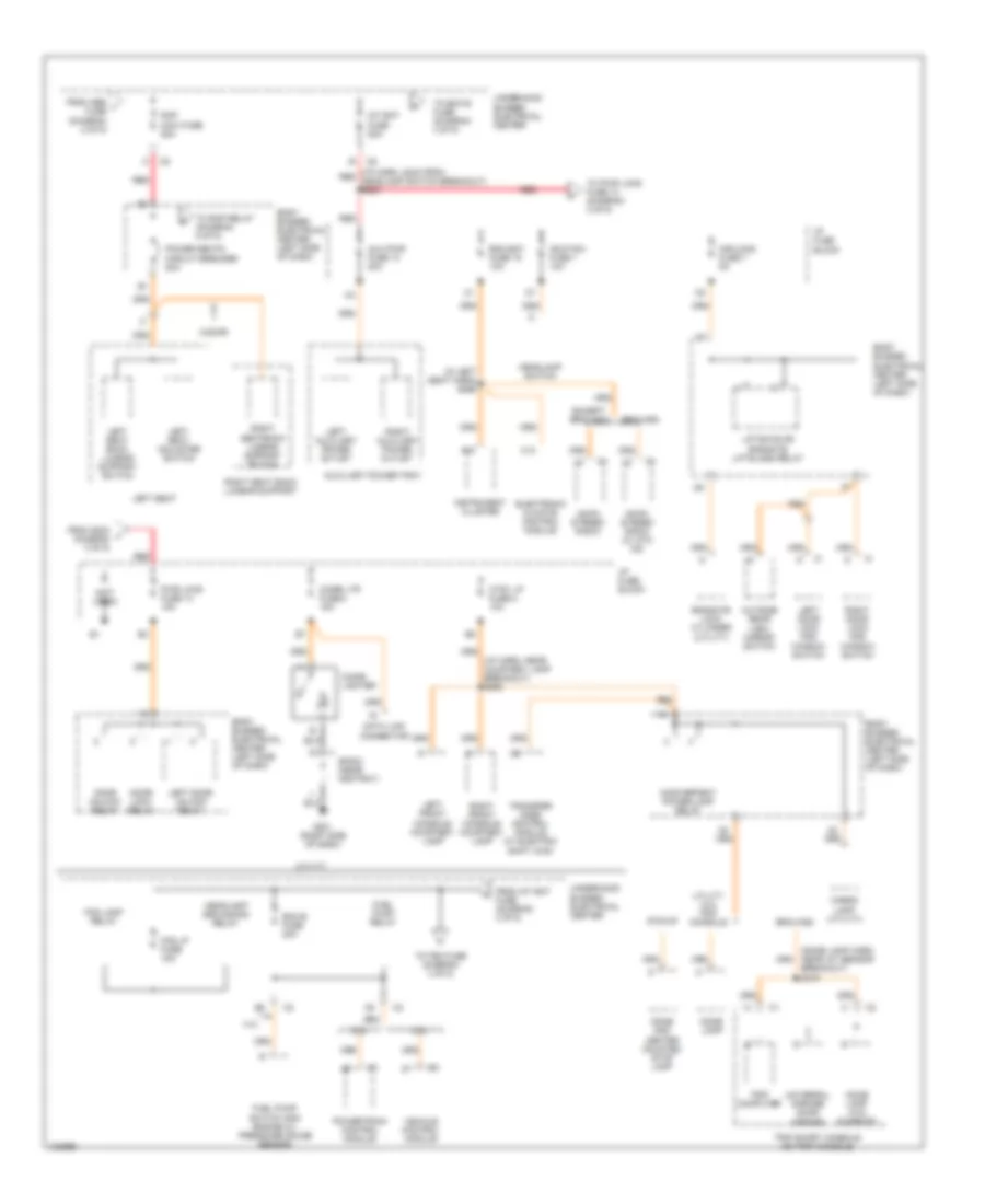
Power Distribution Wiring Diagram (2 of 5) for GMC Sonoma 1998
List of elements for Power Distribution Wiring Diagram (2 of 5) for GMC Sonoma 1998:
- (body harn, near rear doors breakout) s309
- (not used)
- 2 door
- 4 door
- A/c compressor clutch relay
- A/t
- A/t controls (floor shift)
- Abs fuse 60a
- Acc
- Automatic day/ night mirror (utility)
- B/u lp fuse 25 25a
- B11
- B12
- Back-up lamp switch
- Blower motor relay
- Body bussed electrical center
- Btsi fuse 10a
- C10
- C12
- C211
- D12
- Electronic brake control module assembly
- From b/u lp fuse diagram 2 of 5)
- From ign a fuse diagram 1 of 5)
- From oxygen b fuse diagram 1 of 5)
- Haz lp fuse 20a
- Hazard switch (sport side pickup)
- Headlamp switch
- Hvac fuse 30a
- Ign b maxi fuse 50a
- Ign c fuse 20a
- Ign e fuse 27 10a
- Ignition switch
- Left back-up lamp (pickup)
- Left back-up lamp (utility)
- Lock
- M/t
- Off
- Park lamp relay
- Pnk
- Prk lp fuse 20a
- Pulse width modulating drive motor
- Rear defogger relay (utility)
- Red
- Right back-up lamp (pickup)
- Right back-up lamp (utility)
- Run
- Sp204 (center front of dash)
- Sp400 (center of rear crossmember) (pickup)
- Start
- Stop lamp switch
- Stud 2 maxi fuse 30a
- To clstr fuse (diagram 4 of 5)
- To crank fuse (diagram 4 of 5)
- To ign e fuse (diagram 2 of 5)
- To rap maxi fuse (diagram 3 of 5)
- To rap relay (diagram 5 of 5)
- To s204 (diagram 5 of 5)
- Trailer wiring provisions
- Trailer wiring provisions (utility w/ m/t)
- Transfer case control module
- Transmission range switch
- Trl b/u fuse 10a
- Underhood bussed electrical center
- Veh b/u fuse 15a
- W/ climate control
- W/o climate control
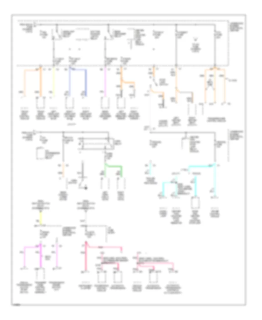
Power Distribution Wiring Diagram (3 of 5) for GMC Sonoma 1998
List of elements for Power Distribution Wiring Diagram (3 of 5) for GMC Sonoma 1998:
- (dome lamp harn, near iat sensor breakout) s310
- (i/p harn, 40cm from red headlamp switch breakout) s223
- (i/p harn, near courtesy lamp breakout) s208
- (in left seat harn) s266
- (not used)
- 2.2l
- 4-door
- 4.3l
- A10
- Am/fm stereo radio
- Am/fm stereo radio (w/ atc cd)
- Aux pwr fuse 13 20a
- Auxiliary power tray
- Body bussed electrical center (left side of dash)
- Bravada
- C12
- Cargo lamp (utility)
- Cigar lighter
- Cigar ltr fuse 2 15a
- Ctsy lp fuse 8 10a
- Data link connector
- Dome and center mounted stop lamp
- Dome lamp
- Dome lamp (w/o sunroof)
- Door lock relay
- Door unlock relay
- Ecm b fuse 20a
- Electronic climate control module
- Endgate lock cylinder (utility)
- Except bravada
- Fog lamp relay
- Fog lp fuse 15a
- From abs i fuse (diagram 2 of 5)
- From int bat fuse (diagram 3 of 5)
- From s223 j diagram 3 of 5)
- Fuel pump relay
- Fuel pump switch and engine oil pressure gauge sensor
- G201 (right side of dash)
- Hdlp sw fuse 1 10a
- Headlamp grounding relay
- Headlamp switch
- I/p fuse block
- Inadvertent power lamp relay
- Instrument cluster
- Int bat fuse 50a
- Left auxiliary power outlet
- Left door lock and window switch
- Left door unlock relay
- Left front console courtesy lamp
- Left seat
- Left seat adjuster switch
- Left seat back lumbar support switch
- Liftgate or endgate liftglass relay
- Mir/lcks fuse 7 5a
- Outside rear view mirror switch
- Pickup
- Power seats circuit breaker 20a
- Powertrain control module
- Pwr lcks fuse 14 15a
- Rap maxi fuse 50a
- Rdo bat fuse 19 10a
- Red
- Right auxiliary power outlet
- Right door lock and window switch
- Right front console courtesy lamp
- Right seat back lumbar support
- Right seatback lumbar support switch
- Sp203 (near ashtray)
- To ecm b fuse (diagram 3 of 5)
- To pwr lcks fuse 14 (diagram 3 of 5)
- To rap relay (diagram 5 of 5)
- To tbc fuse (diagram 4 of 5)
- Transfer case control module (w/ electric shift 4wd)
- Trip computer
- Trip short console or trip console
- Underhood bussed electrical center
- Universal garage door opener
- Utility
- Utility w/o trip console
- Vehicle control module
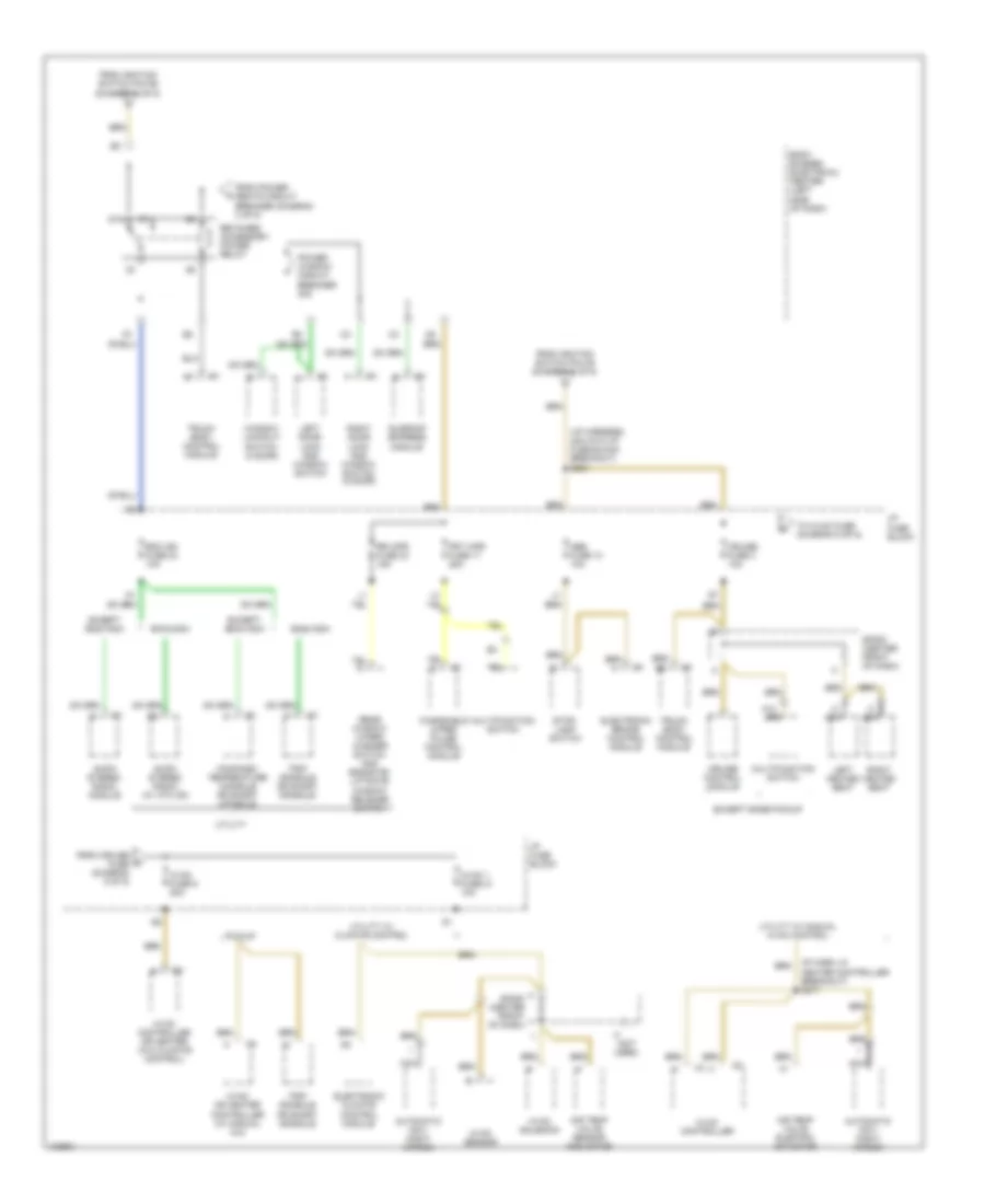
Power Distribution Wiring Diagram (4 of 5) for GMC Sonoma 1998
List of elements for Power Distribution Wiring Diagram (4 of 5) for GMC Sonoma 1998:
- 2.2l
- 4.3l
- A/c compressor clutch relay
- A/c fuse 10a
- Atc fuse 20a
- Automatic transmission
- Automatic transmission controls (w/ floor shift)
- C175
- Center high mounted stop lamp relay (pickup)
- Center high mounted stop- lamp resistor
- Chmsl/ cargo lamp
- Clstr fuse 11 10a
- Crank fuse 10a
- Cruise control module
- D11
- D14
- D15
- D16
- Daytime running lights relay
- Dome and center high mounted stoplamp
- Estc 4wd
- From atc m fuse (diagram 4 of 5)
- From ecm b fuse (diagram 3 of 5)
- From ignition switch pin d1 (diagram 2 of 5)
- Hazard switch (utility)
- Headlamp power relay
- Horn fuse 15a
- Horn relay
- Horn switch
- Htdmir fuse 10a
- Htdseat fuse 20a
- I/p fuse block
- Instrument cluster
- Left headlamp low beam bulb
- Left heated seat (utility)
- Left horn high a note
- Left outside rearview mirror
- Lt hdlp fuse 10a
- Manual transmission clutch start switch
- Nca
- Pickup
- Pnk
- Pnk (body harn, 13cm from blower motor breakout) s113
- Pnk (eng harn, 20cm from a/c pressure sensor breakout)
- Powertrain control module
- Rear defogger relay
- Rear window defogger grid
- Rear window/ wiper motor
- Right headlamp high beam bulb
- Right headlamp low beam bulb
- Right heated seat (utility)
- Right horn low f note
- Right outside rearview mirror
- Rr defog fuse 30a
- Rr w/w fuse 39 15a
- Rt hdlp fuse 10a
- S129
- S405 (body harn, 10cm before chmsl breakout)
- Stop lamp switch
- Stoplp fuse 20a
- Tbc fuse 10a
- To a/c fuse (diagram 4 of 5)
- Trailer wiring provisions
- Transfer case control module
- Transfer case control module assembly
- Transmission range switch (a/t)
- Trchmsl fuse 10a
- Truck body control module
- Underhood bussed electrical center
- Utility
- Vechmsl fuse 10a
- Vehicle control module
- W/ awd
- W/ estc 4wd
Power Distribution Wiring Diagram (5 of 5) for GMC Sonoma 1998
List of elements for Power Distribution Wiring Diagram (5 of 5) for GMC Sonoma 1998:
- (i/p harness, 4cm into i/p fuse block breakout) s204
- (ip harn, in heater controller breakout) s217
- (not used)
- 87a
- A nca
- Abs fuse 10 10a
- Air temp valve electric actuator
- Air temp valve sensor and motor
- Am/fm stereo radio (w/ atc cd)
- Am/fm stereo radio module
- Automatic day/ night mirror
- Baavada
- Body bussed electrical center (left side of dash)
- Compass/ temperature console or short console
- Cruise control module
- Cruise fuse 3 10a
- Electronic brake control module
- Electronic climate control module
- Except baavada
- Except base pickup
- From cruise fuse (diagram 5 of 5)
- From ignition switch pin c6 (diagram 2 of 5)
- From ignition switch pin d6 (diagram 2 of 5)
- From power seats circuit breaker (diagram 3 of 5)
- Frt wpr fuse 17 25a
- Hvac 1 fuse 21 10a
- Hvac controller
- Hvac controller or heater (w/o climate control)
- Hvac fuse 9 20a
- Hvac or heater controller (w/ manual a/c)
- Hvac sensor
- Hvac solenoid
- I/p fuse block
- Left door lock and window switch
- Left heated seat
- Multifunction switch
- Nca
- Pickup
- Power window circuit breaker 30a
- Rdo ign fuse 24 10a
- Rear window wiper/ washer switch and endgate/ liftgate window release switch
- Retained accessory power relay
- Right door lock and window switch (2 door)
- Right heated seat
- Rr wpr fuse 23 15a
- Sp200 (center front of dash)
- Stop- lamp switch
- Sunroof express module
- To hvac fuse (diagram 5 of 5)
- Trip console or short console
- Truck body control module
- Utility
- Utility w/ climate control
- Utility w/ manual hvac control
- Window lockout switch (4 door)
- Windshield wiper pulse control module