POWER DISTRIBUTION
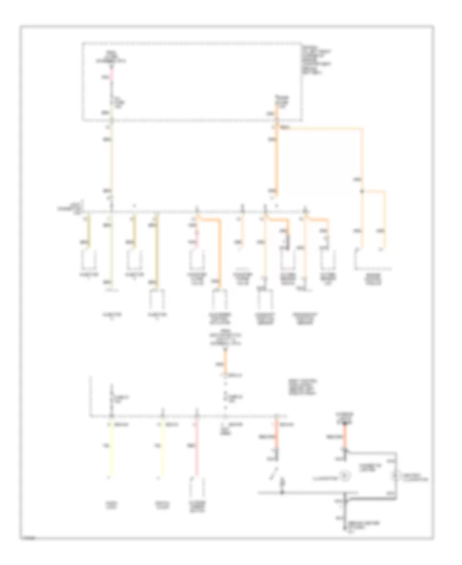
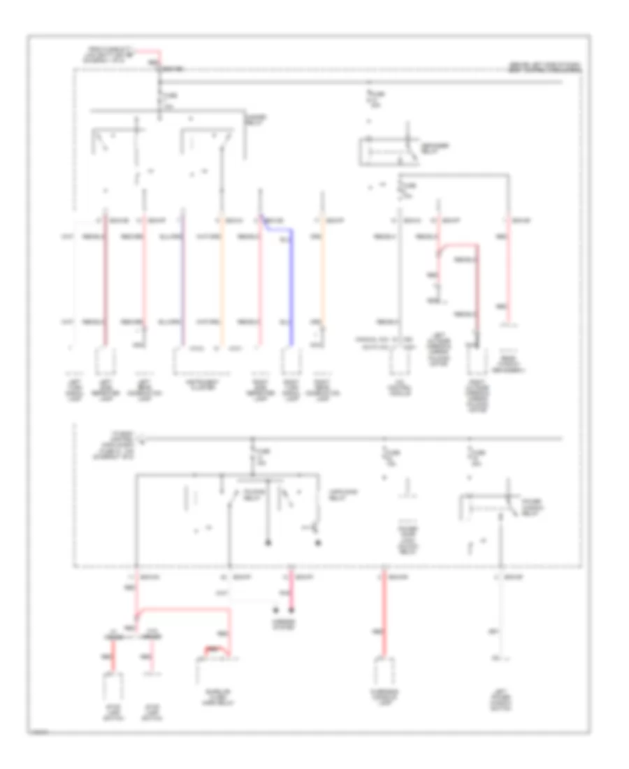
Power Distribution Wiring Diagram (1 of 8) for Hyundai Tiburon 2003

List of elements for Power Distribution Wiring Diagram (1 of 8) for Hyundai Tiburon 2003:
- (2.0l)
- (2.7l)
- (in left front corner of engine compartment, behind battery) e/r box
- 2.0l
- 2.0l 2.7l
- 2.7l
- 2.7l 2.0l
- A/c relay
- A/t control relay
- Abs control module
- Acc
- Battery
- Battery ground
- Blower relay
- Burglar alarm relay
- C133-1
- C133-2 c33
- C137 c37
- C33
- C36-2 c136-2
- Condenser
- Condenser fan relay 1
- Condenser fan relay 2
- Drl control module
- Drl fuse 15a
- E20-1
- E20-2
- E61-1
- E61-2
- E68 e63
- Ec01
- Ec01 ec101
- Ec02 ec102
- Ec101
- Ecu fuse 10a
- Engine control module
- Engine control relay
- From fusible link (batt) a 120a (diagram 1 of 8)
- Front fog lamp relay
- Frt fog fuse 15a
- Fuel pump relay
- Fusible link (abs 1) 30a
- Fusible link (abs 2) 30a
- Fusible link (batt) 120a
- Fusible link (batt) 50a
- Fusible link (blow) 30a
- Fusible link (cond) 30a
- Fusible link (ecu) 30a
- Fusible link (ign) 30a
- Fusible link (rad) 30a
- Generator
- Generator (2.0l)
- Generator fusible link 120a
- H/lp (high) fuse 15a
- H/lp (low) fuse 15a
- Head- lamp relay (high)
- Head- lamp relay (low)
- Horn & a/con fuse 15a
- Horn relay
- Ignition coil 1
- Ignition coil 2
- Ignition switch
- Joint connector e56
- Lock
- Nca
- Pnk
- Radiator fan relay
- Red
- Start
- Start motor
- Start relay
- Start solenoid
- To body control module box (fuse 15, 10a) (diagram 4 of 8)
- To body control module box (fuse 17, 10a) (diagram 5 of 8)
- To body control module box (fuse 23, 15a) (diagram 2 of 8)
- To fuse 7, 10a (diagram 6 of 8)
- To fusible link (ign) 30a (diagram 1 0f 8)
- To inj fuse 15a (diagram 2 of 8)
- To inj fuse 15a (diagram 3 of 8)
- Transaxle control module
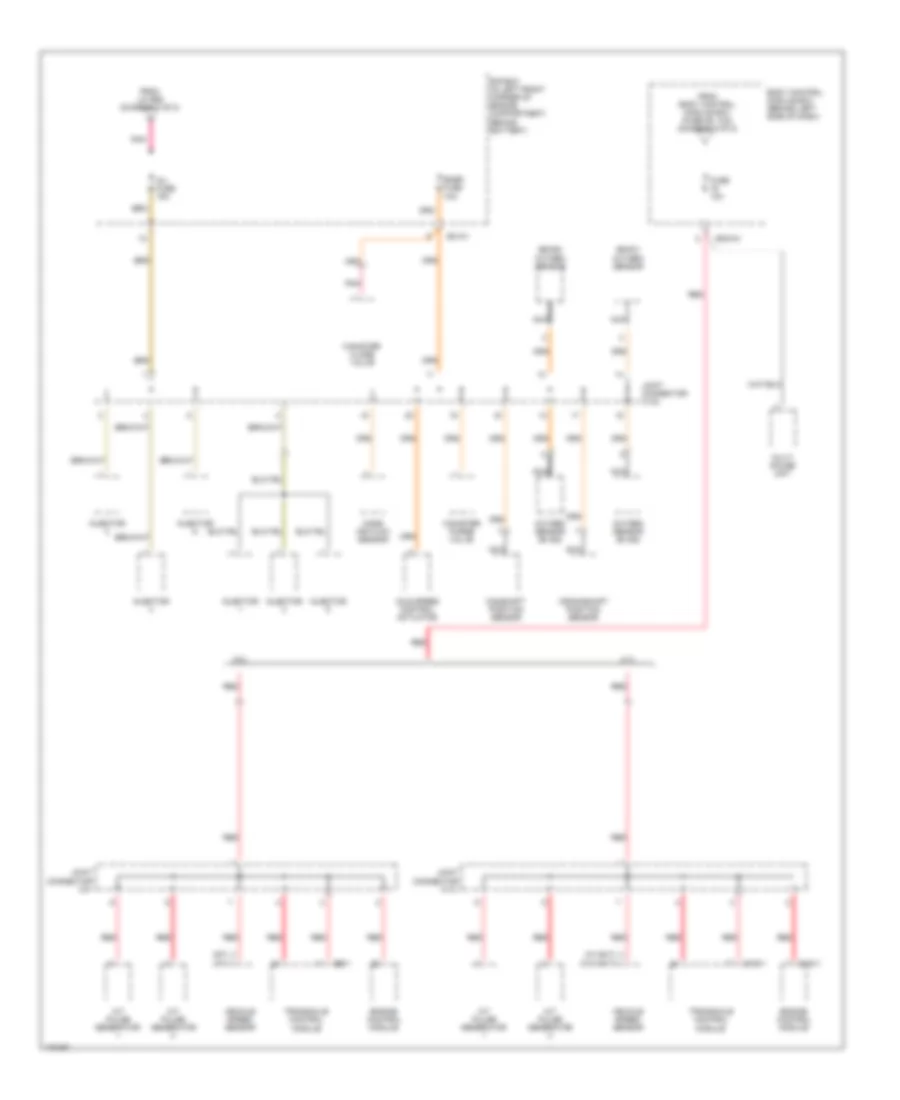
Power Distribution Wiring Diagram (2 of 8) for Hyundai Tiburon 2003
List of elements for Power Distribution Wiring Diagram (2 of 8) for Hyundai Tiburon 2003:
- (behind center of dash) g11
- (not used)
- Ashtray illumination
- Audio (low)
- Bcm-fe
- Bcm-im
- Bcm-km
- Bcm-lm
- Body control module box (behind left side of dash)
- Camshaft position sensor
- Canister close valve
- Canister purge valve
- Cigarette lighter
- Crankshaft position sensor
- Digital clock
- E/r box (in left front corner of engine compartment, behind battery)
- Ec01
- Engine control module
- From ignition switch (cavity 4) (diagram 1 of 8)
- From j/c e56 (diagram 1 of 8)
- Fuse 23 15a
- Fuse 27 10a
- Idle speed control actuator
- Illumination
- Inj fuse 15a
- Injector
- Interior lights system
- Joint connector c42
- Nca
- Outside mirror switch
- Oxygen sensor (down)
- Oxygen sensor (up)
- Pnk
- Red
- Snsr fuse 1oa
Power Distribution Wiring Diagram (3 of 8) for Hyundai Tiburon 2003
List of elements for Power Distribution Wiring Diagram (3 of 8) for Hyundai Tiburon 2003:
- (b2/s1) oxygen sensor
- (b2/s2) oxygen sensor
- (m/t) (a/t)
- (w/ 5m/t) (w/o 5m/t)
- 2.0l
- 2.7l
- A/t pulse generator
- Bcm-im
- Body control module box (behind left side of dash)
- C133-1
- C136-1
- C36-1
- Camshaft position sensor
- Canister close valve
- Canister purge valve
- Crankshaft position sensor
- E/r box (in left front corner of engine compartment, behind battery)
- Ec101
- Engine control module
- From body control module box (fuse 26, 10a) (diagram 5 of 8)
- From j/c e56 (diagram 1 of 8)
- Fuse 10a
- Idle speed control actuator
- Inj fuse 15a
- Injector
- Joint connector c141
- Joint connector c142
- Joint connector c41
- Mass air flow sensor
- Multi gauge unit
- Nca
- Oxygen sensor (b1/s2)
- Pnk
- Red
- Snsr fuse 1oa
- Transaxle control module
- Vehicle speed sensor
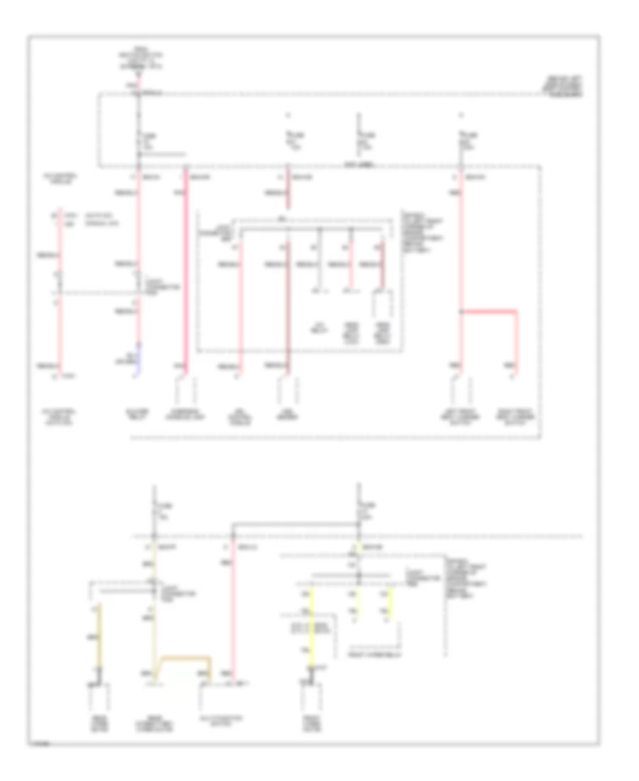
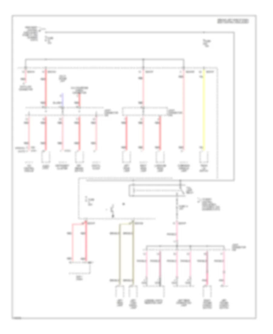
Power Distribution Wiring Diagram (4 of 8) for Hyundai Tiburon 2003
List of elements for Power Distribution Wiring Diagram (4 of 8) for Hyundai Tiburon 2003:
- (2.0l) (2.7l)
- (auto a/c)
- (behind left side of dash) body control module box
- (manual a/c)
- (not used)
- A/c control module
- A/c control module (auto a/c)
- A/c relay
- Aqs sensor
- Bcm-ce
- Bcm-ff
- Bcm-im
- Bcm-km
- Bcm-lm
- Bcm-mr
- Blower relay
- C107
- Drl control module
- E/r box (in left front corner of engine compartment, behind battery)
- Ec02 ec102
- From ignition switch (cavity 3) (diagram 1 of 8)
- Front wiper motor
- Front wiper relay
- Fuse 10a
- Fuse 15a
- Fuse 1oa
- Fuse 2oa
- Head lamp relay (high)
- Head lamp relay (low)
- Joint connector e56
- Joint connector m35
- Joint connector m46
- Left front seat warmer switch
- M01-1
- M19-1
- M20
- Multi-function switch
- Nca
- Overhead console lamp
- Pnk
- Rear intermittent wiper motor
- Rear wiper motor
- Red
- Right front seat warmer switch
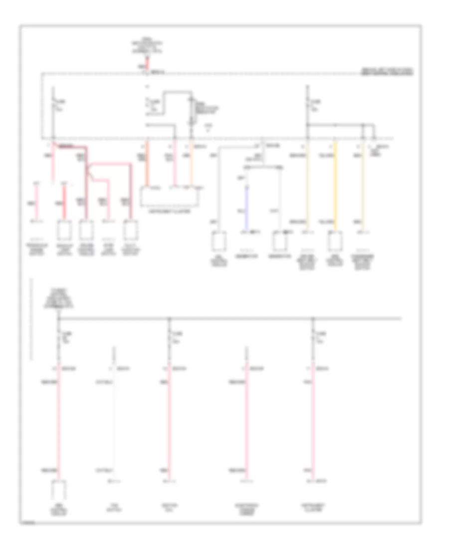
Power Distribution Wiring Diagram (5 of 8) for Hyundai Tiburon 2003
List of elements for Power Distribution Wiring Diagram (5 of 8) for Hyundai Tiburon 2003:
- (behind left side of dash) body control module box
- 2.0l
- 2.7l
- A/t
- Abs control module
- Atd
- Back-up lamp switch
- Bcm-ai (not used)
- Bcm-ce
- Bcm-im
- Bcm-km
- Bcm-lm
- Bcm-mr
- Cruise control module
- Driver seat belt buckle switch
- Drl control module
- E20-2
- E61-2
- Electronic chrome mirror
- From ignition switch (cavity 6) (diagram 1 of 8)
- Fuse 10a
- Fuse 15a
- Fuse 20a
- Generator
- Ignition coil
- Instrument cluster
- M/t
- M10-1
- M10-2
- Multi- function switch
- Passenger seat belt buckle switch
- Pnk
- Pre- excitation resistor
- Red
- Srs control module
- Stop lamp switch
- Tcs switch
- To body control module box (fuse 16, 10a) (diagram 3 of 8)
- Transaxle range switch
Power Distribution Wiring Diagram (6 of 8) for Hyundai Tiburon 2003
List of elements for Power Distribution Wiring Diagram (6 of 8) for Hyundai Tiburon 2003:
- (auto a/c)
- (behind left side of dash) body control module box
- (diagram 1 of 8)
- (manual a/c)
- A/c control module
- Bcm-ce
- Bcm-de
- Bcm-ff
- Bcm-gf
- Bcm-im
- Bcm-km
- Bcm-mr
- Burglar alarm horn relay
- Defogger relay
- Folding relay
- From fusible link (batt) 50a b
- Fuse 10a
- Fuse 15a
- Fuse 30a
- Hazard relay
- Instrument cluster
- Left outside mirror & mirror folding motor
- Left power window switch
- Left rear combination lamp
- Left side repeater lamp
- Left turn signal lamp
- M10-1
- M10-2
- M19-1
- M20
- Mirrors system
- Nca
- Overhead console lamp
- Pnk
- Power door lock/ unlock relay
- Power window relay
- Rear window defogger(+)
- Red
- Right outside mirror & mirror folding motor
- Right rear combination lamp
- Right side repeater lamp
- Right turn signal lamp
- Stop lamp switch
- To body control module box (fuse 18, 10a) (diagram 7 of 8)
- Unfolding relay
- W/ cruise
- W/o cruise
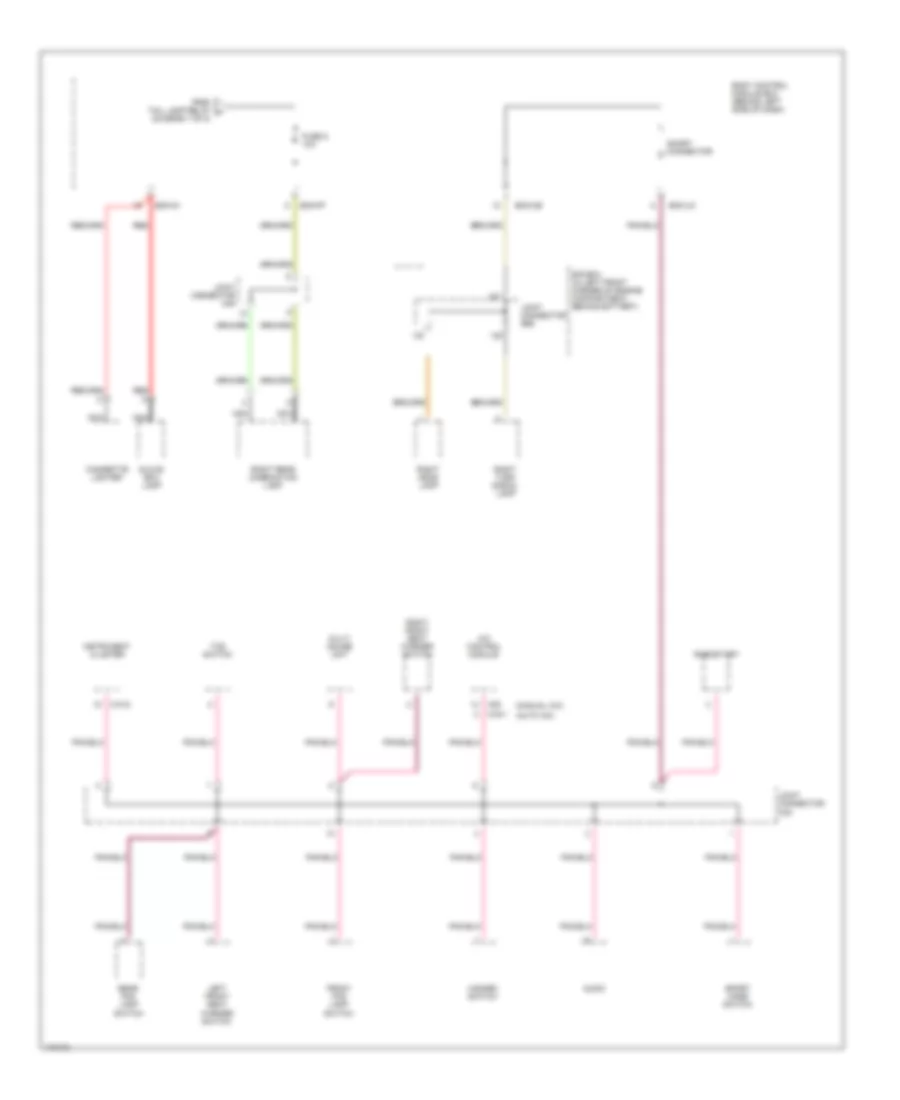
Power Distribution Wiring Diagram (7 of 8) for Hyundai Tiburon 2003
List of elements for Power Distribution Wiring Diagram (7 of 8) for Hyundai Tiburon 2003:
- (auto)
- (behind left side of dash) body control module box
- (low)
- (manual)
- A/c control module
- Amp 1 (high)
- Audio
- Bcm-ce
- Bcm-ff
- Bcm-im
- Bcm-km
- Bcm-mr
- Data link connector
- Digital clock
- From body control g module box (fuse 13, 15a) (diagram 6 of 8)
- Fuse 10a
- Fuse 14 10a
- Fuse 15a
- Fuse 20a
- Instrument cluster
- Joint connector m35
- Joint connector m46
- Key remind switch
- Left door lamp
- Left head lamp
- Left power window switch
- Left rear combination lamp
- Left turn signal lamp
- License lamp & rear fog lamp
- Luggauge room lamp
- M10-2
- M19-1
- M20
- M63-1
- Multi gauge unit
- Multipurpose check connector
- Nca
- Overhead console lamp
- Pnk
- Red
- Right door lamp
- Right power window switch
- Tail lamp relay
- To body control module box (to fuse 9, 10a) (diagram 8 of 8)
- Trunk lid switch
Power Distribution Wiring Diagram (8 of 8) for Hyundai Tiburon 2003
List of elements for Power Distribution Wiring Diagram (8 of 8) for Hyundai Tiburon 2003:
- (auto a/c)
- (manual a/c)
- A/c control module
- Audio
- Bcm-ce
- Bcm-ff
- Bcm-im
- Bcm-jm
- Body control module box (behind left side of dash)
- Cigarette lighter
- E/r box (in left front corner of engine compartment, behind battery)
- From tail lamp relay h (diagram 7 of 8)
- Front fog lamp switch
- Fuse 9 10a
- Glove box lamp
- Hazard switch
- Instrument cluster
- Joint connector e56
- Joint connector m33
- Joint connector m45
- Left front seat warmer switch
- M10-2
- M19-1
- M20
- Multi gauge unit
- Nca
- Rear fog lamp switch
- Red
- Rheostart
- Right front seat warmer switch
- Right head lamp
- Right rear combination lamp
- Right turn signal lamp
- Short connector
- Sport mode switch
- Tcs switch