POWER DISTRIBUTION
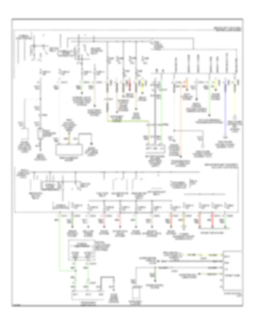
Power Distribution Wiring Diagram (1 of 2) for Jaguar XKR 2012

List of elements for Power Distribution Wiring Diagram (1 of 2) for Jaguar XKR 2012:
- (behind left kick panel) central junction box
- (left side of engine compt) power distribution box
- (not used)
- 5.0l
- 5.0l sc
- Acc relay
- Air conditioning system
- Anti-lock brakes system
- Anti-theft & memory systems
- Auxiliary junction box (behind rear seat backrest)
- Ba001
- Ba002
- Battery
- Battery junction box (left side of battery)
- Bo001
- Bo002
- Bp002
- Bt001
- Ca010
- Ca011
- Ca012
- Ca015
- Ca019
- Ca022
- Ca023
- Ca025
- Ca101
- Cc008
- Cigar lighter relay
- Computer data lines system
- Computer data lines, power windows, door locks, mirrors & starting/ charging systems
- Cooling fans system
- Cruise control system
- Door locks & anti-theft systems
- Ems main relay
- Ems secondary relay
- Engine controls & anti-lock brakes systems
- Engine controls & transmissions systems
- Engine controls system
- Fl037
- Fl038
- Fl039
- Fl040
- Fl041
- Fl042
- Fl043
- Fl044
- Fl045
- Fl051
- Fl100
- Fr001
- From central junction box (diagram 1 of 2)
- From fuse 20 c (diagram 1 of 2)
- Front cigar lighter
- Fuse 1 25a
- Fuse 10 15a
- Fuse 12 10a
- Fuse 13 15a
- Fuse 13 25a
- Fuse 14 15a
- Fuse 15 10a
- Fuse 17 15a
- Fuse 17 5a
- Fuse 175a
- Fuse 18 30a
- Fuse 18 5a
- Fuse 19 5a
- Fuse 2 10a
- Fuse 2 15a
- Fuse 2 5a
- Fuse 20 40a
- Fuse 22 20a
- Fuse 26 40a
- Fuse 28 30a
- Fuse 28 40a
- Fuse 29 30a
- Fuse 3 5a
- Fuse 30 30a
- Fuse 32 30a
- Fuse 35 80a 100a
- Fuse 400a
- Fuse 6 15a
- Fuse 6 5a
- Fuse 7 5a
- Fuse 9 15a
- Fuse 9 5a
- G03ar (left rear of engine compt)
- G10br (behind right kick panel)
- G14al (under center console)
- Headlights system
- Horn relay
- Ignition relay
- Instrument cluster system
- Inter- cooler water pump relay
- Interior lights system
- Ip004
- Left windshield heater relay
- Memory systems
- Power distribution box (left side of engine compt)
- Power wash relay
- Power windows, door locks, mirrors & starting/ charging systems
- Power windows, mirrors & memory systems
- Red
- Right windshield heater relay
- Road pricing connector
- Shift interlock system
- Starter relay
- Starting/ charging system
- To central junction box (diagram 2 of 2)
- To fuse 1 (diagram 2 of 2)
- To fuse 3 (diagram 1 of 2)
- To restraints ignition relay (diagram 2 of 2)
- To road pricing connector (diagram 1 of 2)
- To start control unit (diagram 2 of 2)
- Transmissions & shift interlock systems
- Transmissions system
- Uhegos relay
- Warning systems
- Wiper fast/slow relay
- Wiper park relay
Power Distribution Wiring Diagram (2 of 2) for Jaguar XKR 2012
List of elements for Power Distribution Wiring Diagram (2 of 2) for Jaguar XKR 2012:
- (behind left kick panel) central junction box
- (behind rear seat backrest) auxiliary junction box
- (under center console) g14ar
- Acc rly ctrl
- Active exhaust relay
- Anti-lock brakes & transmissions systems
- Batt
- Battery backed sounder (right rear of engine compt)
- Blower motor relay
- Ca012
- Ca013
- Ca015
- Ca016
- Ca018
- Ca021
- Ca022
- Ca024
- Ca025
- Ca101
- Cc001
- Cc007
- Cellular phones system
- Central junction box (behind left kick panel)
- Computer data lines system
- Cruise control system
- Delayed power off relay
- Door locks system
- Electronic suspension system
- Engine controls & cruise control systems
- Engine controls system
- Exterior lights & cruise control systems
- Fl048
- Fl050
- Fl07
- Fl081
- Fpdb ign ctrl
- Fpdb ign rly ctrl
- Fr068
- From auxiliary junction box (diagram 2 of 2)
- From central junction box j (diagram 1 of 2)
- From fuse 10 (diagram 1 of 2)
- From fuse 28 a (diagram 1 of 2)
- From power distribution box (diagram 1 of 2)
- Front accessory socket
- Fuel pump relay
- Fuse 10 10a
- Fuse 12 10a
- Fuse 14 10a
- Fuse 14 15a
- Fuse 16 15a
- Fuse 19 10a
- Fuse 20a
- Fuse 21 15a
- Fuse 22 5a
- Fuse 23 10a
- Fuse 24 10a
- Fuse 25 10a
- Fuse 30 40a
- Fuse 31 30a
- Fuse 32 40a
- Fuse 5a
- Fuse 8 5a
- G14ar (under center console)
- G22ar (left rear of luggage compt)
- G43al (behind glove box)
- Gnd
- Ign sply 1 cabin
- Ign sply 1 fwd
- Ign sply 2 cabin
- Ign sply 2 fwd
- Ignition relay
- Instrument cluster
- Instrument cluster system
- Interior lights, air conditioning & power tops systems
- Internal b+ power distribution
- Internal electronics
- Internal power distribution
- Ip031
- Ip052
- Lin
- Navigation & sound systems
- Power amplifier cooling fan (w/ premium audio)
- Power tops system
- Rear accessory socket
- Rear heated window relay
- Red
- Relay link
- Restraints ignition relay
- Ring break diagnostics fusible link
- Seats system
- Seats, warning, air conditioning & mirrors systems
- Shift interlock system
- Sound & exterior lights systems
- Sound systems
- Sply
- Start control unit
- Start/ stop sw 1
- Start/ stop sw 2
- Sw 1
- Sw 2
- To rear accessory socket (diagram 2 of 2)
- Transit mode
- Transmission shift module
- Transmissions & shift interlock, systems