POWER DISTRIBUTION
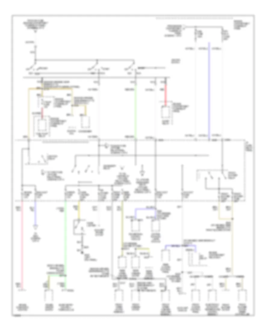
Power Distribution Wiring Diagram (1 of 4) for Mercury Villager GS 1998

List of elements for Power Distribution Wiring Diagram (1 of 4) for Mercury Villager GS 1998:
- (engine harness, in engine compt fuse/relay panel) s115
- (engine harness, near breakout in-line circuit breaker no 1) s226
- (engine harness, near breakout to anti-theft relay) s133
- (engine harness, near breakout to grommet to interior of vehicle)
- (engine harness, near breakout to injector n0 1) s114
- (engine harness, near breakout to injector no 1) s118
- (engine harness, near breakout to intake air temp sensor) s111
- (engine harness, near breakout to pcm relay) s112
- (engine harness, near grommet to engine compt) s123
- (i/p harness, right side of dash) s227
- (left seat jumper harness) s307
- A/light (h/l) relay
- Abs fuse 20a
- Abs fuse 30a
- Alt fuse 10a
- Alt fuse 120a
- Anti-theft relay
- Autolamp module
- Battery
- Breakout to j/c 2) s225
- C2032
- C275
- Combination switch
- Cooling fan hi 1 relay
- Cooling fan hi 2 relay
- Cooling fan lo relay
- Data link connector no 1
- Daytime running lamps module
- Eng cont fuse 10a
- Engine compartment fuse/relay panel
- Engine compartment relay box
- Fuel injector no 1
- Fuel injector no 2
- Fuel injector no 3
- Fuel injector no 4
- Fuel injector no 5
- Fuel injector no 6
- Generator/ voltage regulator
- H/l l fuse 15a
- H/l r fuse 15a
- Headlamp switch
- Horn fuse 15a
- Horn relay
- Hydraulic actuator assembly
- Ign fuse 30a
- Inj fuse 10a
- Inline circuit breaker no 1
- Inline circuit breaker no 2
- Left lumbar seat switch
- Left power seat switch
- Nca
- Power window relay
- Powertrain control module
- Powertrain control module relay
- Pwr wdw fuse 30a
- Rad fan fuse 65a
- Red
- Right power seat switch
- S113
- S129 (engine harness, left side of engine)
- S223
- S228 (i/p harness, behind left side of dash)
- Sec fuse 7.5a
- Smart entry control /timer module
- Starter assembly
- To ignition switch (diagram 2 of 4)
- To main fuse (engine compartment fuse/relay panel) (diagram 2 of 4)
- To rr def fuse (engine compartment fuse/relay panel) (diagram 3 of 4)
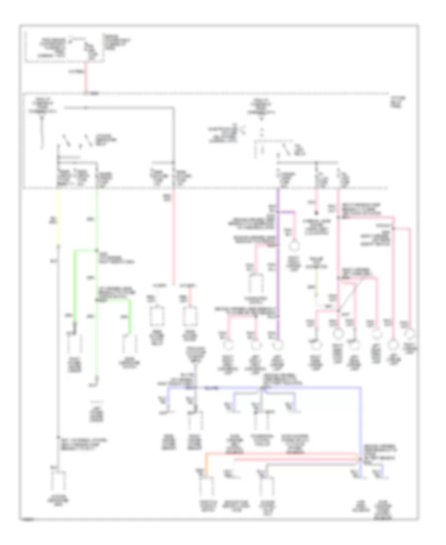
Power Distribution Wiring Diagram (2 of 4) for Mercury Villager GS 1998
List of elements for Power Distribution Wiring Diagram (2 of 4) for Mercury Villager GS 1998:
- (body harness, breakout to power mirror switch) s279
- (engine harn, near breakout to intake air temp sensor)
- (engine harness, near breakout to ignition coil) s120
- (engine harness, near breakout to intake air temp sensor)
- (i/p harness, center of dash) s2013
- (i/p harness, near breakout j/c no 2) s250
- A/c cont fuse 7.5a
- A/c relay
- Acc
- Accessory relay
- Air bag diagnostic monitor
- Air bag fuse 10a
- Autolamp module
- Auxiliary power outlet
- C202
- C2032
- C204
- C206
- C275
- Cigar lighter
- Cigar lighter fuse 20a
- Condenser
- Daytime running lamps module
- Electronic automatic temperature control assembly
- Eng cont fuse 10a
- Eng cont fuse 7.5a
- Engine compartment fuse/relay panel
- Engine compartment relay box
- F pump fuse 15a
- From engine compartment c fuse/relay panel (diagram 1 of 4)
- From ign fuse (engine compartment fuse/relay panel) (diagram 1 of 4)
- Front blower fuse 20a
- Front blower motor
- Front blower motor/ speed controller
- Front blower relay
- Front climate control panel
- Front washer motor
- Front wiper fuse 20a
- Front wiper motor assembly
- Front wiper/ washer amplifier assembly
- Frt blw fuse 65a
- Fuel pump relay
- G200 (left kick panel)
- I/p fuse/ relay panel
- Ignition coil
- Ignition relay
- Ignition switch
- Inhibit relay
- Main fuse 100a
- Mirror fuse 10a
- Nca
- Nca (engine harness, near breakout to engine compt fuse/relay panel) s119
- Off
- Power mirror switch
- Powertrain control module
- Rear climate control panel
- Rear washer motor
- Rear wiper fuse 10a
- Rear wiper motor assembly
- Rear wiper/ washer amplifier
- Red
- Rr power plug fuse 20a
- Run
- S127
- S160
- S205
- S236 (i/p harness, near breakout to front blower motor)
- S249 (i/p harness, right side of dash)
- Smart entry control/ timer module
- Start
- To audio fuse (i/p fuse/ relay panel) (diagram 4 of 4)
- To liftgate defroster relay (i/p fuse/ relay panel) (diagram 3 of 4)
- To s242 (diagram 3 of 4)
- To tail lamp relay (i/p fuse/ relay panel) (diagram 3 of 4)
- To turn fuse (i/p fuse/ relay panel) (diagram 4 of 4)
- W/ eatc
- W/o eatc
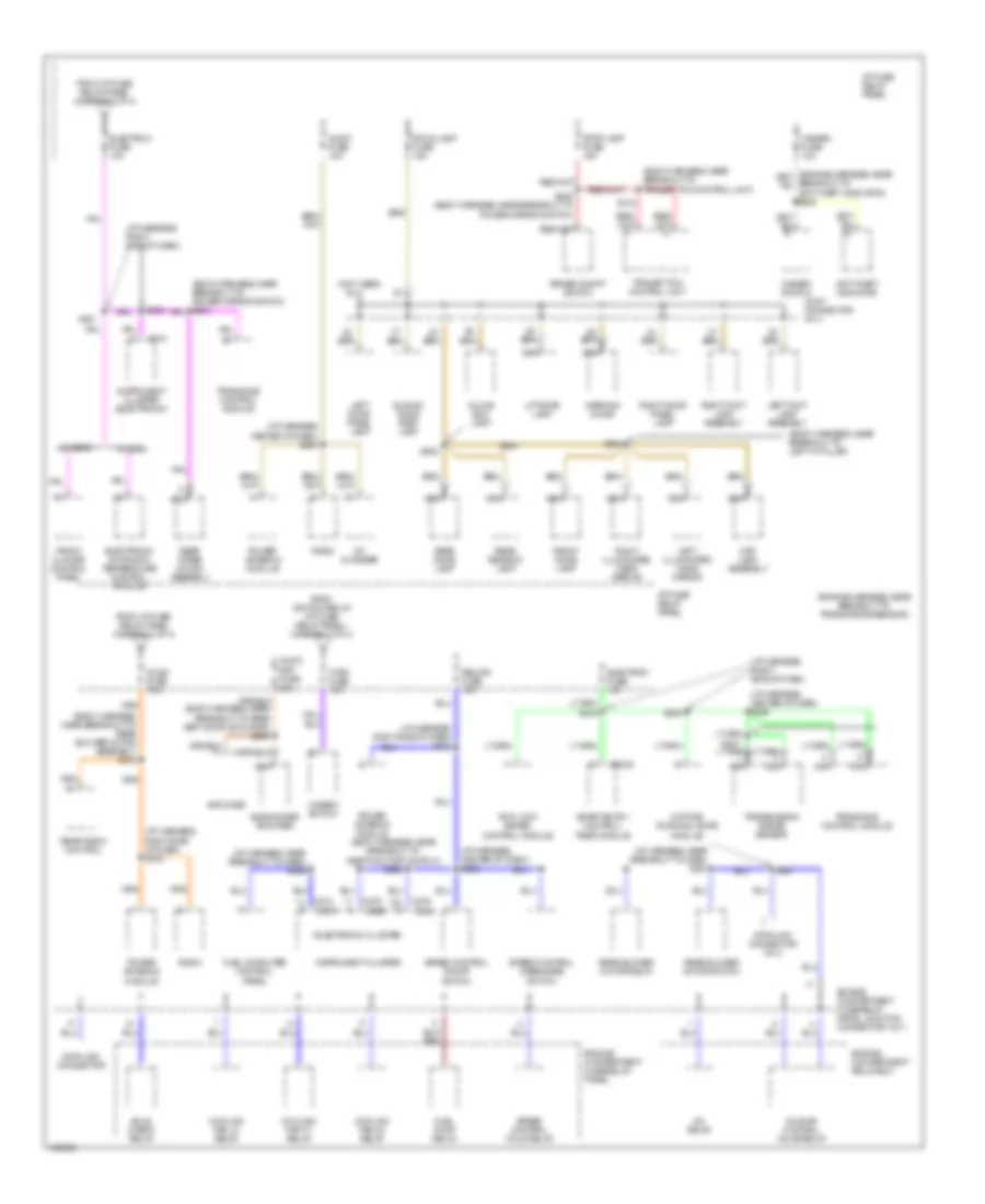
Power Distribution Wiring Diagram (3 of 4) for Mercury Villager GS 1998
List of elements for Power Distribution Wiring Diagram (3 of 4) for Mercury Villager GS 1998:
- (body harness, left wheelwell) s406
- (body harness, near breakout to rear vent door actuator) s317
- (engine harness, near breakout to anti-theft indicator) s241
- (engine harness, near breakout to intake air temp sensor) s124
- (engine harness, near breakout to intake air temp sensor) s154
- (engine harness, near grommet to interior) s125
- (i/p harness, near breakout to power mirror switch) s235
- (i/p harness, right side of dash) s242
- (moveable liftgate)
- C202
- C275
- Combination switch
- Corner lamps fuse 10a
- Engine compartment fuse/relay panel
- Evap canister purge control solenoid
- Evap canister purge vacuum cut valve bypass solenoid
- Evap canister vent control solenoid
- Exhaust gas recirculation valve
- From eng cont fuse (diagram 2 of 4)
- From engine compartment fuse/relay panel (diagram 1 of 4)
- From i/p fuse/relay panel (diagram 2 of 4)
- Front heated oxygen sensor
- Heated mirror fuse 10a
- I/p fuse/ relay panel
- I/p illum fuse 7.5a
- Idle air control valve no 2
- Interior lamps system (instrument illumination)
- Left front marker lamp
- Left front park/ cornering lamp
- Left license lamp
- Left power/ heated mirror
- Left rear marker lamp
- Left rear park/ stop lamp
- Liftgate defroster grid
- Liftgate defroster relay
- Map/ baro solenoid
- Nca
- Pnk
- Powertrain control module
- Rear blower fuse 15a
- Rear blower motor
- Rear blower motor relay
- Rear defog fuse 20a
- Rear defroster switch
- Rear heated oxygen sensor
- Right front marker lamp
- Right front park/ cornering lamp
- Right license lamp
- Right power/ heated mirror
- Right rear marker lamp
- Right rear park/ stop lamp
- Rr def fuse 45a
- S126 (engine harness, near breakout to generator/ voltage regulator)
- S252 (i/p harness, right side of dash)
- S337 (body harness, near breakout to g411)
- S407
- S408 (body harness, left rear side of vehicle)
- Tail lamp fuse 10a
- Tail lamp relay
- Throttle position switch
- To electron fuse (i/p fuse/ relay panel) (diagram 4 of 4)
- Trailer tow connector
- W/ eatc
- W/o eatc
Power Distribution Wiring Diagram (4 of 4) for Mercury Villager GS 1998
List of elements for Power Distribution Wiring Diagram (4 of 4) for Mercury Villager GS 1998:
- (body harness, near breakout to inertia cutoff switch) s260
- (body harness, near breakout to left "a" pillar)
- (body harness, near breakout to rear blower motor assembly) s313
- (body harness, near breakout to trailer tow control unit)
- (engine harness, near breakout to trans range sensor)
- (i/p harness, center of dash) s234
- (i/p harness, center of dash) s246
- (i/p harness, center of dash) s258
- (i/p harness, near breakout to dash) s259
- (i/p harness, near breakout to dash) s261
- (i/p harness, right side of dash)
- (i/p harness, right side of dash) s224
- (i/p harness, right side of dash) s316
- (not used)
- * electronic cluster
- A/c relay
- Amplifier
- Anti-lock brake control module
- Anti-theft indicator
- Audio amp fuse 20a
- Audio fuse 10a
- Audio fuse 7.5a
- Brake on/off switch
- Bulb check relay
- C2032
- C266
- C268
- C270
- C272
- C274
- C276
- Cd changer
- Cooling fan h1 relay
- Cooling fan h2 relay
- Cooling fan lo relay
- Data link connector
- Data link connector no 2
- Daytime running lamps module
- Electron fuse 10a
- Electronic automatic temperature control module
- Engine compartment fuse/relay panel
- Engine compartment fuse/relay panel junction connector no 1
- Engine compartment relay box
- From i/p fuse/ relay panel (diagram 2 of 4)
- From i/p fuse/ relay panel (diagram 3 of 4)
- From ignition relay (i/p fuse/ relay panel) (diagram 2 of 4)
- Front climate control panel
- Front dome lamp
- Fuel computer control panel
- Fuel pump relay
- Glove box lamp
- Hazard fuse 10a
- Hazard switch
- I/p fuse/ relay panel
- Idle air control valve relay
- Instrument cluster
- Instrument cluster (electronic)
- Joint connector no 3
- Left door panel lamp
- Left foot lamp assembly
- Left illuminated visor mirror
- Liftgate lamp
- Map lamp assembly
- Nca
- Power antenna module
- Radio
- Rear blower motor relay
- Rear blower motor switch
- Rear dome lamp
- Rear radio control
- Rear reading lamp
- Rear wiper motor assembly
- Relays fuse 10a
- Right door panel lamp
- Right foot lamp assembly
- Right illuminated visor mirror
- Room lamp fuse 15a
- S231
- S232
- S237
- S239 (body harness, near breakout to power mirror switch)
- S245
- S312
- S902
- S904
- Sliding door step lamp
- Smart entry control/ timer module
- Speed control disengage switch
- Speed control hold relay
- Speed control on/off switch
- Stop lamp fuse 15a
- Subwoofer amplifier
- Trailer tow control unit
- Transaxle control module
- Transmission range sensor
- Turn fuse 10a
- W/ eatc
- W/o eatc
- Warning chime